EP0491552B1 - Refrigerant charge detection system for an air conditioning system - Google Patents
Refrigerant charge detection system for an air conditioning system Download PDFInfo
- Publication number
- EP0491552B1 EP0491552B1 EP91311702A EP91311702A EP0491552B1 EP 0491552 B1 EP0491552 B1 EP 0491552B1 EP 91311702 A EP91311702 A EP 91311702A EP 91311702 A EP91311702 A EP 91311702A EP 0491552 B1 EP0491552 B1 EP 0491552B1
- Authority
- EP
- European Patent Office
- Prior art keywords
- refrigerant
- circuit
- state
- voltage
- output
- Prior art date
- Legal status (The legal status is an assumption and is not a legal conclusion. Google has not performed a legal analysis and makes no representation as to the accuracy of the status listed.)
- Expired - Lifetime
Links
- 239000003507 refrigerant Substances 0.000 title claims description 152
- 238000001514 detection method Methods 0.000 title claims description 36
- 238000004378 air conditioning Methods 0.000 title claims description 12
- 230000003321 amplification Effects 0.000 claims description 22
- 238000003199 nucleic acid amplification method Methods 0.000 claims description 22
- 238000002834 transmittance Methods 0.000 claims description 10
- 230000000007 visual effect Effects 0.000 claims 3
- 239000010687 lubricating oil Substances 0.000 description 11
- 239000012071 phase Substances 0.000 description 10
- 239000007791 liquid phase Substances 0.000 description 9
- 230000007423 decrease Effects 0.000 description 8
- 239000012808 vapor phase Substances 0.000 description 8
- 230000001681 protective effect Effects 0.000 description 5
- 238000010586 diagram Methods 0.000 description 4
- 239000007789 gas Substances 0.000 description 3
- 239000003990 capacitor Substances 0.000 description 2
- 238000000605 extraction Methods 0.000 description 2
- 239000011521 glass Substances 0.000 description 2
- 238000013459 approach Methods 0.000 description 1
- 230000005540 biological transmission Effects 0.000 description 1
- 238000001816 cooling Methods 0.000 description 1
- 239000007792 gaseous phase Substances 0.000 description 1
- 238000007689 inspection Methods 0.000 description 1
- 239000007788 liquid Substances 0.000 description 1
- 230000001050 lubricating effect Effects 0.000 description 1
- 230000003287 optical effect Effects 0.000 description 1
- 238000007789 sealing Methods 0.000 description 1
- XLYOFNOQVPJJNP-UHFFFAOYSA-N water Substances O XLYOFNOQVPJJNP-UHFFFAOYSA-N 0.000 description 1
Images


Classifications
-
- F—MECHANICAL ENGINEERING; LIGHTING; HEATING; WEAPONS; BLASTING
- F25—REFRIGERATION OR COOLING; COMBINED HEATING AND REFRIGERATION SYSTEMS; HEAT PUMP SYSTEMS; MANUFACTURE OR STORAGE OF ICE; LIQUEFACTION SOLIDIFICATION OF GASES
- F25B—REFRIGERATION MACHINES, PLANTS OR SYSTEMS; COMBINED HEATING AND REFRIGERATION SYSTEMS; HEAT PUMP SYSTEMS
- F25B41/00—Fluid-circulation arrangements
- F25B41/006—Fluid-circulation arrangements optical fluid control arrangements
-
- B—PERFORMING OPERATIONS; TRANSPORTING
- B60—VEHICLES IN GENERAL
- B60H—ARRANGEMENTS OF HEATING, COOLING, VENTILATING OR OTHER AIR-TREATING DEVICES SPECIALLY ADAPTED FOR PASSENGER OR GOODS SPACES OF VEHICLES
- B60H1/00—Heating, cooling or ventilating [HVAC] devices
- B60H1/00507—Details, e.g. mounting arrangements, desaeration devices
- B60H1/00585—Means for monitoring, testing or servicing the air-conditioning
-
- F—MECHANICAL ENGINEERING; LIGHTING; HEATING; WEAPONS; BLASTING
- F25—REFRIGERATION OR COOLING; COMBINED HEATING AND REFRIGERATION SYSTEMS; HEAT PUMP SYSTEMS; MANUFACTURE OR STORAGE OF ICE; LIQUEFACTION SOLIDIFICATION OF GASES
- F25B—REFRIGERATION MACHINES, PLANTS OR SYSTEMS; COMBINED HEATING AND REFRIGERATION SYSTEMS; HEAT PUMP SYSTEMS
- F25B45/00—Arrangements for charging or discharging refrigerant
Definitions
- the present invention relates to an air conditioning system suitable for use in vehicles, and more particularly to an air conditioning system for a cooling apparatus having a photoelectric detecting device for detecting a state of refrigerant circulating in a refrigerant circuit.
- FIGS. 8 to 10 A typical conventional air conditioning system for vehicles is shown in FIGS. 8 to 10.
- a refrigerant such as freon gas is circulated in refrigerant circuit 1 formed from pipe 2.
- Compressor 3, condenser 4, expansion valve 8 and evaporator 5 are provided in refrigerant circuit 1 sequentially in the circulation direction of the refrigerant which is shown by arrows "A"
- the endothermic surface of evaporator 5 is exposed to the interior of the vehicle (not shown).
- the refrigerant is compressed by compressor 3, the refrigerant is transformed in phase from a high-pressure gas to a high-pressure liquid in condenser 4 and further to a low-pressure gas as it passes through expansion valve 8 and evaporator 5.
- Expansion valve 8 When the refrigerant is transformed from a liquid phase to a gaseous phase (vapor phase) by evaporator 5, the refrigerant absorbs heat from the interior of the vehicle and the vehicle interior is cooled.
- Expansion valve 8 is provided between condenser 4 and evaporator 5. Expansion valve 8 reduces the pressure of the refrigerant to a relatively low pressure so that the liquefied high-pressure refrigerant can be easily vaporized when it passes through evaporator 5.
- a receiver tank 6 is provided in refrigerant circuit 1 at a position between condenser 4 and expansion valve 8. Receiver tank 6 temporarily stores refrigerant "F" which has been transformed to a liquid phase. On top of receiver tank 6, an inspection hole 6A is provided for observing the liquefaction of the refrigerant. Receiver tank 6 is connected to introduction pipe 2A and extraction pipe 2B constituting parts of pipe 2, as shown in FIG. 9. A desiccator 7 is provided in receiver tank 6.
- the refrigerant After the water component of the refrigerant introduced into receiver tank 6 through introduction pipe 2A is removed by desiccator 7, the refrigerant is stored in the receiver tank as a liquefied refrigerant.
- the liquefied refrigerant is sent to expansion valve 8 through extraction pipe 2B as shown by arrow "A".
- An optical type (photoelectric) flow sensor 9 is provided in refrigerant circuit 1 at a position between receiver tank 6 and expansion valve 8 as a refrigerant state detecting device.
- Flow sensor 9 comprises an emitter 9A for emitting a light into pipe 2B and a receiver 9B for receiving the light transmitted through the pipe. Emitter 9A and receiver 9B are provided on the pipe aligned with each other.
- Flow sensor 9 detects a phase of the refrigerant passing through pipe 2B, i.e., whether the refrigerant is in a liquid phase.
- a determination circuit 10 is coupled to flow sensor 9. Determination circuit 10 is provided for determining a phase of the refrigerant passing through pipe 2B according to a signal sent from flow sensor 9. Determination circuit 10 is shown in FIG. 10. Determination circuit 10 comprises a constant voltage generation circuit 11, a detection circuit 16 coupled to flow sensor 9, an amplification circuit 20, a comparison circuit 24 and an information output circuit 30.
- Constant voltage generation circuit 11 is coupled to the plus side "B" of a battery (not shown). Constant voltage generation circuit 11 comprises input compensation capacitor 13 and three terminal regulator 14 which are coupled between plus terminal "B” and ground 12. Output compensation capacitor 15 is coupled between the output of three terminal regulator 14 and ground. Constant voltage generation circuit 11 outputs a constant voltage VCC (for example 5V).
- VCC constant voltage
- Detection circuit 16 comprises resistor 17 for controlling a current of emitter 9A, coupled in series to the emitter 9A between the circuit at a voltage of VCC and ground 12, and resistor 18 for controlling a detecting signal of receiver 9B, coupled in series to the receiver 9B between the circuit at the voltage of VCC and ground 12. Junction 19 between receiver 9B and resistor 18 is coupled to amplification circuit 20. Receiver 9B controls a current flowing in accordance with a transmittance of the light transmitted through pipe 2B. A detection voltage "V" controlled in accordance with the above current and the resistance of resistor 18 is output from junction 19 as a detection signal.
- Amplification circuit 20 comprises operational amplifier 21, resistor 22 having a resistance of R1 coupled between the inverting terminal of the operational amplifier and ground 12, and feedback resistor 23 having a resistance of R2 coupled between the inverting terminal and the output terminal of the operational amplifier.
- the non-inverting terminal of operational amplifier 21 is coupled to junction 19 of detection circuit 16.
- Amplification circuit 20 amplifies the voltage "V" output from detection circuit 16 in accordance with the resistances of R1 and R2 of resistors 22 and 23 at amplification factor "A” calculated by the following equation.
- A (R1 + R2)/R1 Output voltage "E” of amplification circuit 20 is calculated by the following equation.
- Output voltage "E" of amplification circuit 20 is input into the non-inverting terminal of operational amplifier 28.
- Output voltage "E” which is input into the non-inverting terminal of operational amplifier 28 and reference voltage Vi set for the inverting terminal thereof are compared in the operational amplifier. If Vi ⁇ E, a determination voltage V0 is output as a high-level signal, and if Vi>E, then the determination voltage V0 is output as a low-level signal.
- Information output circuit 30 is provided for indicating or warning a state of refrigerant charged in refrigerant circuit 1.
- Information output circuit 30 comprises input protective resistor 31, protective resistor 32 coupled between the input protective resistor 31 and ground 12, NPN-type transistor 33 having a switching function whose base is coupled to the input protective resistor 31, and light emitting diode 35 coupled to VCC terminal via control resistor 34 and coupled to the collector of the transistor.
- the emitter of transistor 33 is coupled to ground 12.
- Light emitting diode 35 is placed in, for example, an engine compartment or the interior of a vehicle, and functions as an information lamp.
- a high-level determination voltage V0 is output from comparison circuit 24, a current flows between the base and emitter of transistor 33 via input protective resistor 31, and current flows between the collector and emitter of transistor 33. Diode 35 emits a light by the turning "on" of transistor 33.
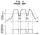
- determination circuit 10 operates, for example, as shown in FIG. 11, when refrigerant is charged into refrigerant circuit 1.
- the refrigerant When the amount of charged refrigerant has not yet reached a proper amount, the refrigerant contains a refrigerant of a vapor phase (bubbles) at a position of pipe 2B where flow sensor 9 is provided and the refrigerant should be in a liquid phase if the amount of charged refrigerant reaches a proper amount. Since the transmissibility of a light through the refrigerant of a mixing phase is low, the amount of a light detected by receiver 9B is small. Therefore, output voltage "V” output from detection circuit 16 is low. The output voltage "V” is amplified to a voltage "E” at an amplification factor "A” by amplification circuit 20.
- the output voltage "E” from amplification circuit 20 is compared with reference voltage Vi in comparison circuit 24. Until output voltage "E” becomes higher than reference voltage Vi, determination voltage V0 output is a low-level signal. As a result, transistor 33 does not turn “on”, and light emitting diode 35 does not operate, thus, indicating that the amount of charged refrigerant has not yet reached a proper amount.
- the refrigerant present at flow sensor 9 in pipe 2B indicates a complete liquid phase. Namely, refrigerant of a vapor phase does not exist. Therefore, the transmission of a light through the refrigerant increases and is detected by receiver 9B.
- Output voltage "V” output from detection circuit 16 becomes high, and a high output voltage “E” amplifying the output voltage "V” at an amplification factor “A” is output from amplification circuit 20.
- the output voltage "E” from amplification circuit 20 is compared with reference voltage Vi in comparison circuit 24. When output voltage "E” exceeds reference voltage Vi, a high-level determination voltage V0 is output from comparison circuit 24.
- Transistor 33 of information circuit 30 turns “on”, and light emitting diode 35 emits a light, indicating that the amount of charged refrigerant has reached a proper amount.
- Flow sensor 9 continues to detect a phase of refrigerant present in refrigerant circuit 1 at a position of the exit side of receiver tank 6, after the system is charged with refrigerant. If the amount of refrigerant in refrigerant circuit 1 decreases, for example, from leakage of the refrigerant, the amount of the refrigerant present in the refrigerant circuit gradually decreases, and bubbles of refrigerant are generated.
- the mixing state of liquid and vapor phases of the refrigerant is detected by flow sensor 9, and output voltage "E" of detection circuit 16 decreases as shown by the characteristic curve "S1" in FIG. 11 and the output of a high-level determination voltage V0 is stopped. The operation of light emitting diode 35 is stopped indicating insufficient amount of refrigerant in the system.
- output voltage "E” does not precisely correspond to the state of the refrigerant circulating in refrigerant circuit 1.
- This output voltage "E” is compared with reference voltage Vi.
- output voltage "E” becomes lower than reference voltage Vi
- the output of a high-level determination voltage V0 is stopped, and when output voltage "E” becomes higher than reference voltage Vi again, a high-level determination voltage V0 is output again, as shown in Fig. 11.
- the output of a high-level determination voltage V0 is repeated. Since the flashing of light emitting diode 35 is repeated in accordance with the variation of determination voltage V0, whether or not the amount of refrigerant is proper cannot be accurately determined.
- US-A-4644755 discloses a refrigerant circulating circuit of an air conditioning system, the circulating circuit comprising a compressor; a condenser coupled to an output of the compressor; an evaporator coupled to an output of the condenser and to an input of the compressor; state detecting means coupled between the condenser and the evaporator for detecting a phase of refrigerant in the circulating circuit and outputting a detection signal related to the detected phase; and determining means coupled to the state detecting means and including a comparison circuit which compares the detection signal with a first reference signal and outputs a signal indicating sufficient refrigerant if the detection signal exceeds the first reference signal; and according to a first aspect of the present invention, such a circuit is characterised in that the comparison circuit continues to output the signal indicating sufficient refrigerant until the detection signal falls below a second reference signal which is lower than the first reference signal.
- US-A-4644755 discloses an apparatus for sensing a state of charge of refrigerant in a refrigerant circulating circuit comprising sensing means for sensing the phase state of refrigerant in the circulating circuit and outputting a state signal related to the detected phase state of the refrigerant; and detecting means including comparison means for comparing the state signal with a first reference signal and outputting a signal indicating sufficient refrigerant if the state signal exceeds the first reference signal; and according to a second aspect of the present invention, such an apparatus is characterised in that the comparison means continues to output the signal indicating sufficient refrigerant until the state signal falls below a second reference signal which is lower than the first reference signal.
- the output signal from the comparison circuit continues to be issued unless the detection signal drops below the second reference value.
- An operator or a drive can precisely and easily recognize that the amount of refrigerant in the refrigerant circuit is maintained within the range of a proper amount. Further, if the detection signal drops below the second reference value by, for example, a leakage of refrigerant, it can be also precisely recognized that the amount of refrigerant in the refrigerant circuit is insufficient.
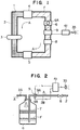
- FIGS. 1-4 illustrate an air conditioning system according to a first embodiment of the present invention.
- FIGS. 1, 2 and 4 as to elements corresponding to the elements which have been explained in FIGS. 8-10, explanation is omitted by attaching the same reference designators to the elements corresponding to the elements in FIGS. 8-10.
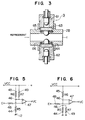
- FIG. 3 illustrates a flow sensor 9 provided on pipe 2B as a photoelectric refrigerant state detecting device.
- Flow sensor 9 comprises a photoelectric sensor.
- Flow sensor 9 includes emitter 61 emitting a light towards the interior of pipe 2B and receiver 62 for receiving the light transmitted through the pipe (and refrigerant in the pipe).
- Sensor 9 is attached to pipe 2B so that emitter 61 and receiver 62 are aligned with each other.
- O-rings 65 and 66 are interposed between sensor 9 and pipe 2B for sealing therebetween.
- the light emitted from emitter 61 is sent through sight glass 63 into the interior of pipe 2B.
- the light transmitted through the pipe is received by receiver 62 through sight glass 64.
- Flow sensor 9 detects transmittance of the light transmitted by emitter 61 and received by receiver 62.
- the transmittance of the light transmitted through pipe 2B corresponds to the mixing ratio of refrigerant in a liquid phase and refrigerant in a vapor phase existing or flowing in the pipe. As the amount of refrigerant increases, the ratio of refrigerant in a vapor phase to that in a liquid phase decreases and the transmittance of the light increases. Therefore, flow sensor 9 can determine an increase in the amount of refrigerant by measuring transmittance of the light transmitted through pipe 2B.
- Flow sensor 9 is coupled to detection circuit 16 of determination circuit 41.
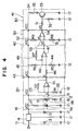
- FIG. 4 illustrates determination circuit 41.
- Determination circuit 41 comprises a comparison circuit 42 in addition to constant voltage generation circuit 11, detection circuit 16 coupled to flow sensor 9, amplification circuit 20 and an information output circuit 30 which have been already explained in FIG. 10.
- Comparison circuit 42 is provided between amplification circuit 20 and an information output circuit 30 and comprises a hysteresis comparator circuit 43 and an inverting circuit 50.
- Hysteresis comparator circuit 43 comprises an operational amplifier 47 having an inverting terminal, a non-inverting terminal and a feedback circuit, a potential divider and a resistor 48 for an input signal coupled to the inverting terminal of the operational amplifier.
- the potential divider comprises a resistor 44 having a resistance of R5 and a resistor 45 having a resistance of R6. Junction 46 between resistors 44 and 45 is coupled to the non-inverting terminal of operational amplifier 47.
- a resistor 49 having a resistance of R7 is provided in the feedback circuit of operational amplifier 47 and coupled to the non-inverting terminal of the operational amplifier.
- the output voltage "E" of amplification circuit 20 is input into the inverting terminal of operational amplifier 47 via resistor 48.
- the hysteresis comparator circuit 43 constitutes an equivalent circuit shown in FIG. 5.
- a first reference voltage VH is set as a first reference value for comparing with output voltage "E" by the following equation.
- VH [(R5 ⁇ (R6 + R7))/(R5 ⁇ (R6 + R7) + R6 ⁇ R7)] ⁇ VCC
- Output voltage "E” is input into the inverting terminal of operational amplifier 47, first reference voltage VH is input into the non-inverting terminal of the operational amplifier 47 and the output voltage "E” and the first reference voltage VH are compared in the operational amplifier 47. If VH is lower than "E" (VH ⁇ E), comparison voltage VC is output as a low-level signal.
- VH > E comparison voltage VC is output as a high-level signal.
- hysteresis comparator circuit 43 constitutes an equivalent circuit shown in FIG. 6.
- a second reference voltage VL is set as a second reference value by the following equation.
- the first reference voltage VH is greater than the second reference voltage VL (VH > VL).
- VL [(R5 ⁇ R7)/(R6 ⁇ (R5 + R7) + R5 ⁇ R7)] ⁇ VCC
- comparison voltage VC is output as a high-level signal.
- comparison voltage VC is output as a low-level signal.
- the output of comparison voltage VC is continued until the output voltage "E” becomes less than second reference voltage VL. If the output voltage "E” becomes less than the second reference voltage VL by, for example, leakage of refrigerant, a high-level comparison voltage VC is output again.
- Inverting circuit 50 is provided between hysteresis comparator circuit 43 and information output circuit 30.
- Inverting circuit 50 comprises an operational amplifier 54 having an inverting terminal and a non-inverting terminal, and a potential divider coupled to the non-inverting terminal.
- the potential divider comprises a resistor 51 having a resistance of R8 and a resistor 52 having a resistance of R9. Junction 53 between resistors 51 and 52 is coupled to the non-inverting terminal of operational amplifier 54.
- the inverting terminal of operational amplifier 54 is coupled to the output terminal of hysteresis comparator circuit 43. Comparison voltage VC output from the hysteresis comparator circuit is input into the inverting terminal of the operational amplifier 54.
- the output terminal of operational amplifier 54 is coupled to information output circuit 30, and a determination voltage V0 having a predetermined high-level signal value, output from the operational amplifier, is input into the information output circuit.
- a reference voltage VK is set by the following equation, according to the resistances of resistors 51 and 52.
- VK (R8/(R8 + R9)) ⁇ VCC
- reference voltage VK is set lower than comparison voltage VC (VK ⁇ VC).
- comparison voltage VC When comparison voltage VC is output as a high-level signal from hysteresis comparator circuit 43, determination voltage V0 from operational amplifier 54 is output as a low-level signal.
- determination voltage V0 When the comparison voltage VC is output as a low-level signal, determination voltage V0 having a predetermined high-level signal value is output from operational amplifier 54. Determination voltage V0 is output inverted from comparison voltage VC, as shown in FIG. 7.
- receiver 9B of flow sensor 9 detects a transmittance of the light transmitted from emitter 9A through pipe 2B, that is, through the refrigerant passing through the pipe.
- Detection circuit 16 outputs a detection voltage "V” in accordance with a signal sent from flow sensor 9.
- the detection voltage "V” is amplified by amplification circuit 20, and the amplification circuit issues an output voltage "E".
- the output voltage "E” is input into hysteresis comparator circuit 43.
- hysteresis comparator circuit 43 the output voltage "E” is compared with first and second reference voltages.
- Comparison voltage VC output from hysteresis comparator circuit 43 is input into inverting circuit 50.
- the comparison voltage VC is inverted in inverting circuit 50, and the inverted voltage is output from the inverting circuit as determination voltage V0.
- the determination voltage V0 is input into information output circuit 30.
- the present state of refrigerant in refrigerant circuit 1 is indicated by the operation of light emitting diode 35 in information output circuit 30.
- detection voltage "V” is also at a low level.
- the detection voltage "V” is amplified by amplification circuit 20, and an amplified output voltage "E” is input into hysteresis comparator circuit 43. In hysteresis comparator circuit 43, the output voltage "E” is compared with first reference voltage VH.
- a high-level comparison voltage VC is output from hysteresis comparator circuit 43.
- Inverting circuit 50 outputs a low-level determination voltage V0 in accordance with the issue of the comparison voltage VC.
- light emitting diode 35 in information output circuit 30 does not operate, thereby indicating an insufficient amount of refrigerant.
- Inverting circuit 50 outputs a high-level determination voltage V0 in accordance with low-level output of the comparison voltage VC. As a result, light emitting diode 35 in information output circuit 30 operates, thereby indicating that the amount of charged refrigerant has reached a proper amount.
- inverting circuit 50 continues to output a high-level determination voltage V0.
- light emitting diode 35 in information output circuit 30 continues to operate, thereby accurately indicating that the amount of refrigerant in refrigerant circuit 1 is maintained within a proper range of amount.
- comparison circuit 42 comprises hysteresis comparator circuit 43 and inverting circuit 50, and first reference voltage VH and second reference voltage VL are set in the hysteresis comparator circuit.
- the reference voltages VH and VL are appropriately set and the difference between the reference voltages is set appropriately large. Therefore, even if output voltage "E” (detection voltage "V") varies by translucent lubricating oil circulating in refrigerant circuit 1 together with refrigerant, inverting circuit 50 continues to output a high-level determination voltage V0 and light emitting diode 35 continues to operate for indicating that the refrigerant in the refrigerant circuit is maintained to be within a range of a proper amount.
- the above control for removing the affection of translucent lubricating is also effective when the amount of refrigerant in refrigerant circuit 1 gradually decreases by, for example, a leakage of the refrigerant
- the state that the refrigerant leaks to an undesired level can be also accurately detected by the operation wherein, when output voltage "E" approaches second reference voltage VL, light emitting diode 35 flashes depending on the variation of the output voltage "E", and when the output voltage "E" becomes lower than second reference voltage, the insufficient amount of refrigerant can be accurately indicated by operation of the light emitting diode.
- comparison circuit 42 is constructed from hysteresis comparator circuit 43 and inversion circuit 50 in the embodiment, the comparison circuit can be constituted by only the hysteresis comparator circuit by connecting potential dividing resistors 44 and 45 and feedback resistor 49 to the inverting terminal of operational amplifier 47 and inputting output voltage "E" into the non-inverting terminal of the operational amplifier.
- the indication device is not particularly restricted.
- a sound transducer or a buzzer can be used as the indication device.
Description
- The present invention relates to an air conditioning system suitable for use in vehicles, and more particularly to an air conditioning system for a cooling apparatus having a photoelectric detecting device for detecting a state of refrigerant circulating in a refrigerant circuit.
- A typical conventional air conditioning system for vehicles is shown in FIGS. 8 to 10. In FIG 8, a refrigerant such as freon gas is circulated in refrigerant circuit 1 formed from
pipe 2.Compressor 3,condenser 4,expansion valve 8 andevaporator 5 are provided in refrigerant circuit 1 sequentially in the circulation direction of the refrigerant which is shown by arrows "A" The endothermic surface ofevaporator 5 is exposed to the interior of the vehicle (not shown). After the refrigerant is compressed bycompressor 3, the refrigerant is transformed in phase from a high-pressure gas to a high-pressure liquid incondenser 4 and further to a low-pressure gas as it passes throughexpansion valve 8 andevaporator 5. When the refrigerant is transformed from a liquid phase to a gaseous phase (vapor phase) byevaporator 5, the refrigerant absorbs heat from the interior of the vehicle and the vehicle interior is cooled.Expansion valve 8 is provided betweencondenser 4 andevaporator 5.Expansion valve 8 reduces the pressure of the refrigerant to a relatively low pressure so that the liquefied high-pressure refrigerant can be easily vaporized when it passes throughevaporator 5. - A
receiver tank 6 is provided in refrigerant circuit 1 at a position betweencondenser 4 andexpansion valve 8.Receiver tank 6 temporarily stores refrigerant "F" which has been transformed to a liquid phase. On top ofreceiver tank 6, aninspection hole 6A is provided for observing the liquefaction of the refrigerant.Receiver tank 6 is connected tointroduction pipe 2A andextraction pipe 2B constituting parts ofpipe 2, as shown in FIG. 9. Adesiccator 7 is provided inreceiver tank 6. - After the water component of the refrigerant introduced into
receiver tank 6 throughintroduction pipe 2A is removed bydesiccator 7, the refrigerant is stored in the receiver tank as a liquefied refrigerant. The liquefied refrigerant is sent toexpansion valve 8 throughextraction pipe 2B as shown by arrow "A". - An optical type (photoelectric)
flow sensor 9 is provided in refrigerant circuit 1 at a position betweenreceiver tank 6 andexpansion valve 8 as a refrigerant state detecting device.Flow sensor 9 comprises anemitter 9A for emitting a light intopipe 2B and areceiver 9B for receiving the light transmitted through the pipe.Emitter 9A andreceiver 9B are provided on the pipe aligned with each other.Flow sensor 9 detects a phase of the refrigerant passing throughpipe 2B, i.e., whether the refrigerant is in a liquid phase. - A
determination circuit 10 is coupled toflow sensor 9.Determination circuit 10 is provided for determining a phase of the refrigerant passing throughpipe 2B according to a signal sent fromflow sensor 9.Determination circuit 10 is shown in FIG. 10.Determination circuit 10 comprises a constant voltage generation circuit 11, adetection circuit 16 coupled toflow sensor 9, anamplification circuit 20, acomparison circuit 24 and aninformation output circuit 30. - Constant voltage generation circuit 11 is coupled to the plus side "B" of a battery (not shown). Constant voltage generation circuit 11 comprises input compensation capacitor 13 and three
terminal regulator 14 which are coupled between plus terminal "B" andground 12.Output compensation capacitor 15 is coupled between the output of threeterminal regulator 14 and ground. Constant voltage generation circuit 11 outputs a constant voltage VCC (for example 5V). -
Detection circuit 16 comprises resistor 17 for controlling a current ofemitter 9A, coupled in series to theemitter 9A between the circuit at a voltage of VCC andground 12, andresistor 18 for controlling a detecting signal ofreceiver 9B, coupled in series to thereceiver 9B between the circuit at the voltage of VCC andground 12. Junction 19 betweenreceiver 9B andresistor 18 is coupled toamplification circuit 20.Receiver 9B controls a current flowing in accordance with a transmittance of the light transmitted throughpipe 2B. A detection voltage "V" controlled in accordance with the above current and the resistance ofresistor 18 is output from junction 19 as a detection signal. -
Amplification circuit 20 comprisesoperational amplifier 21,resistor 22 having a resistance of R1 coupled between the inverting terminal of the operational amplifier andground 12, andfeedback resistor 23 having a resistance of R2 coupled between the inverting terminal and the output terminal of the operational amplifier. The non-inverting terminal ofoperational amplifier 21 is coupled to junction 19 ofdetection circuit 16.Amplification circuit 20 amplifies the voltage "V" output fromdetection circuit 16 in accordance with the resistances of R1 and R2 ofresistors

Output voltage "E" ofamplification circuit 20 is calculated by the following equation.

Comparison circuit 24 comprisesoperational amplifier 28, and potential dividingresistors ground 12.Junction 27 betweenresistors operational amplifier 28. Output voltage "E" ofamplification circuit 20 is input into the non-inverting terminal ofoperational amplifier 28. Reference voltage Vi is set by the respective resistances ofresistors

Output voltage "E" which is input into the non-inverting terminal ofoperational amplifier 28 and reference voltage Vi set for the inverting terminal thereof are compared in the operational amplifier. If Vi<E, a determination voltage V0 is output as a high-level signal, and if Vi>E, then the determination voltage V0 is output as a low-level signal. -
Information output circuit 30 is provided for indicating or warning a state of refrigerant charged in refrigerant circuit 1.Information output circuit 30 comprises inputprotective resistor 31,protective resistor 32 coupled between the inputprotective resistor 31 andground 12, NPN-type transistor 33 having a switching function whose base is coupled to the inputprotective resistor 31, andlight emitting diode 35 coupled to VCC terminal viacontrol resistor 34 and coupled to the collector of the transistor. The emitter oftransistor 33 is coupled toground 12.Light emitting diode 35 is placed in, for example, an engine compartment or the interior of a vehicle, and functions as an information lamp. If a high-level determination voltage V0 is output fromcomparison circuit 24, a current flows between the base and emitter oftransistor 33 via inputprotective resistor 31, and current flows between the collector and emitter oftransistor 33.Diode 35 emits a light by the turning "on" oftransistor 33. - In such a conventional air conditioning system,
determination circuit 10 operates, for example, as shown in FIG. 11, when refrigerant is charged into refrigerant circuit 1. - When the amount of charged refrigerant has not yet reached a proper amount, the refrigerant contains a refrigerant of a vapor phase (bubbles) at a position of
pipe 2B whereflow sensor 9 is provided and the refrigerant should be in a liquid phase if the amount of charged refrigerant reaches a proper amount. Since the transmissibility of a light through the refrigerant of a mixing phase is low, the amount of a light detected byreceiver 9B is small. Therefore, output voltage "V" output fromdetection circuit 16 is low. The output voltage "V" is amplified to a voltage "E" at an amplification factor "A" byamplification circuit 20. The output voltage "E" fromamplification circuit 20 is compared with reference voltage Vi incomparison circuit 24. Until output voltage "E" becomes higher than reference voltage Vi, determination voltage V0 output is a low-level signal. As a result,transistor 33 does not turn "on", andlight emitting diode 35 does not operate, thus, indicating that the amount of charged refrigerant has not yet reached a proper amount. - When the amount of charged refrigerant has reached a proper amount, the refrigerant present at
flow sensor 9 inpipe 2B indicates a complete liquid phase. Namely, refrigerant of a vapor phase does not exist. Therefore, the transmission of a light through the refrigerant increases and is detected byreceiver 9B. Output voltage "V" output fromdetection circuit 16 becomes high, and a high output voltage "E" amplifying the output voltage "V" at an amplification factor "A" is output fromamplification circuit 20. The output voltage "E" fromamplification circuit 20 is compared with reference voltage Vi incomparison circuit 24. When output voltage "E" exceeds reference voltage Vi, a high-level determination voltage V0 is output fromcomparison circuit 24.Transistor 33 ofinformation circuit 30 turns "on", andlight emitting diode 35 emits a light, indicating that the amount of charged refrigerant has reached a proper amount. -
Flow sensor 9 continues to detect a phase of refrigerant present in refrigerant circuit 1 at a position of the exit side ofreceiver tank 6, after the system is charged with refrigerant. If the amount of refrigerant in refrigerant circuit 1 decreases, for example, from leakage of the refrigerant, the amount of the refrigerant present in the refrigerant circuit gradually decreases, and bubbles of refrigerant are generated. The mixing state of liquid and vapor phases of the refrigerant is detected byflow sensor 9, and output voltage "E" ofdetection circuit 16 decreases as shown by the characteristic curve "S1" in FIG. 11 and the output of a high-level determination voltage V0 is stopped. The operation oflight emitting diode 35 is stopped indicating insufficient amount of refrigerant in the system. - In the conventional air conditioning system functioning in such a manner, however, there are the following problems.
- When a refrigerant containing a lubricating oil is charged into refrigerant circuit 1 while
compressor 3 is driven, the lubricating oil separates from the refrigerant depending upon temperature, and a part of the lubricating oil insoluble to the refrigerant sometimes turns translucent, or muddy white, in the refrigerant circulating inpipe 2. Since the lubricating oil circulates in refrigerant circuit together with the refrigerant, when the translucent lubricating oil passes through the position provided withflow sensor 9, the light emitted fromemitter 9A is partially interrupted by the lubricating oil and the transmitted light received byreceiver 9B decreases. Therefore, the characteristic curve of output voltage "E" greatly varies as shown by areas "S2" and "S3" in FIG. 11 when the translucent lubricating oil passes throughflow sensor 9, even after the amount of the charged refrigerant has reached a proper amount. As a result, output voltage "E" does not precisely correspond to the state of the refrigerant circulating in refrigerant circuit 1. This output voltage "E" is compared with reference voltage Vi. When output voltage "E" becomes lower than reference voltage Vi, the output of a high-level determination voltage V0 is stopped, and when output voltage "E" becomes higher than reference voltage Vi again, a high-level determination voltage V0 is output again, as shown in Fig. 11. Thus, the output of a high-level determination voltage V0 is repeated. Since the flashing oflight emitting diode 35 is repeated in accordance with the variation of determination voltage V0, whether or not the amount of refrigerant is proper cannot be accurately determined. - Accordingly, it would be desirable to provide an air conditioning system which can accurately determined whether the amount of charged refrigerant has reached a proper amount and is maintained within the proper amount, even when translucent lubricating oil is in the refrigerant in a refrigerant circuit to improve the reliability of the system.
- US-A-4644755 discloses a refrigerant circulating circuit of an air conditioning system, the circulating circuit comprising a compressor; a condenser coupled to an output of the compressor; an evaporator coupled to an output of the condenser and to an input of the compressor; state detecting means coupled between the condenser and the evaporator for detecting a phase of refrigerant in the circulating circuit and outputting a detection signal related to the detected phase; and determining means coupled to the state detecting means and including a comparison circuit which compares the detection signal with a first reference signal and outputs a signal indicating sufficient refrigerant if the detection signal exceeds the first reference signal; and according to a first aspect of the present invention, such a circuit is characterised in that the comparison circuit continues to output the signal indicating sufficient refrigerant until the detection signal falls below a second reference signal which is lower than the first reference signal.
- US-A-4644755 discloses an apparatus for sensing a state of charge of refrigerant in a refrigerant circulating circuit comprising sensing means for sensing the phase state of refrigerant in the circulating circuit and outputting a state signal related to the detected phase state of the refrigerant; and detecting means including comparison means for comparing the state signal with a first reference signal and outputting a signal indicating sufficient refrigerant if the state signal exceeds the first reference signal; and according to a second aspect of the present invention, such an apparatus is characterised in that the comparison means continues to output the signal indicating sufficient refrigerant until the state signal falls below a second reference signal which is lower than the first reference signal.
- Therefore, even if the detection signal varies due to the generation of translucent lubricating oil in the refrigerant, the output signal from the comparison circuit continues to be issued unless the detection signal drops below the second reference value. An operator or a drive can precisely and easily recognize that the amount of refrigerant in the refrigerant circuit is maintained within the range of a proper amount. Further, if the detection signal drops below the second reference value by, for example, a leakage of refrigerant, it can be also precisely recognized that the amount of refrigerant in the refrigerant circuit is insufficient.
- In the accompanying drawings:
- FIG. 1 is a schematic view of an air conditioning system according to a first embodiment of the present invention.
- FIG. 2 is an enlarged schematic sectional view of a portion from a receiver tank to an expansion valve of the system shown in FIG. 1.
- FIG. 3 is an enlarged sectional view of a photoelectric refrigerant state detecting means of the system shown in FIG. 1.
- FIG. 4 is a diagram of an electric circuit including a determining means for the system shown in FIG. 1.
- FIG. 5 is a diagram of a comparison circuit equivalent to a comparison circuit in the electric circuit shown in FIG. 4, showing a case where a first reference voltage is set.
- FIG. 6 is a diagram of a comparison circuit equivalent to a comparison circuit in the electric circuit shown in FIG. 4, showing a case where a second reference voltage is set.
- FIG. 7 is a graph showing the relationship between time and an output voltage, a comparison voltage and a determination voltage in the electric circuit shown in FIG. 4.
- FIG. 8 is a schematic view of a prior art air conditioning system.
- FIG. 9 is an enlarged schematic sectional view of a portion from a receiver tank to an expansion valve of the prior art system shown in FIG. 8.
- FIG. 10 is a diagram of an electric circuit for the prior art system shown in FIG. 8.
- FIG. 11 is a graph showing the relationship between time and an output voltage and a determination voltage in the prior art electric circuit shown in FIG. 10.
- Referring to the drawings, FIGS. 1-4 illustrate an air conditioning system according to a first embodiment of the present invention. In FIGS. 1, 2 and 4, as to elements corresponding to the elements which have been explained in FIGS. 8-10, explanation is omitted by attaching the same reference designators to the elements corresponding to the elements in FIGS. 8-10.
- FIG. 3 illustrates a
flow sensor 9 provided onpipe 2B as a photoelectric refrigerant state detecting device.Flow sensor 9 comprises a photoelectric sensor.Flow sensor 9 includesemitter 61 emitting a light towards the interior ofpipe 2B andreceiver 62 for receiving the light transmitted through the pipe (and refrigerant in the pipe).Sensor 9 is attached topipe 2B so thatemitter 61 andreceiver 62 are aligned with each other. - O-
rings sensor 9 andpipe 2B for sealing therebetween. The light emitted fromemitter 61 is sent throughsight glass 63 into the interior ofpipe 2B. The light transmitted through the pipe is received byreceiver 62 throughsight glass 64.Flow sensor 9 detects transmittance of the light transmitted byemitter 61 and received byreceiver 62. The transmittance of the light transmitted throughpipe 2B corresponds to the mixing ratio of refrigerant in a liquid phase and refrigerant in a vapor phase existing or flowing in the pipe. As the amount of refrigerant increases, the ratio of refrigerant in a vapor phase to that in a liquid phase decreases and the transmittance of the light increases. Therefore, flowsensor 9 can determine an increase in the amount of refrigerant by measuring transmittance of the light transmitted throughpipe 2B.Flow sensor 9 is coupled todetection circuit 16 ofdetermination circuit 41. - FIG. 4 illustrates
determination circuit 41.Determination circuit 41 comprises acomparison circuit 42 in addition to constant voltage generation circuit 11,detection circuit 16 coupled to flowsensor 9,amplification circuit 20 and aninformation output circuit 30 which have been already explained in FIG. 10.Comparison circuit 42 is provided betweenamplification circuit 20 and aninformation output circuit 30 and comprises ahysteresis comparator circuit 43 and an invertingcircuit 50. -
Hysteresis comparator circuit 43 comprises anoperational amplifier 47 having an inverting terminal, a non-inverting terminal and a feedback circuit, a potential divider and aresistor 48 for an input signal coupled to the inverting terminal of the operational amplifier. The potential divider comprises aresistor 44 having a resistance of R5 and aresistor 45 having a resistance of R6.Junction 46 betweenresistors operational amplifier 47. Aresistor 49 having a resistance of R7 is provided in the feedback circuit ofoperational amplifier 47 and coupled to the non-inverting terminal of the operational amplifier. The output voltage "E" ofamplification circuit 20 is input into the inverting terminal ofoperational amplifier 47 viaresistor 48. Thehysteresis comparator circuit 43 constitutes an equivalent circuit shown in FIG. 5. A first reference voltage VH is set as a first reference value for comparing with output voltage "E" by the following equation.

Output voltage "E" is input into the inverting terminal ofoperational amplifier 47, first reference voltage VH is input into the non-inverting terminal of theoperational amplifier 47 and the output voltage "E" and the first reference voltage VH are compared in theoperational amplifier 47. If VH is lower than "E" (VH < E), comparison voltage VC is output as a low-level signal. If VH is greater than "E" (VH > E), comparison voltage VC is output as a high-level signal. In the case of (VH < E),hysteresis comparator circuit 43 constitutes an equivalent circuit shown in FIG. 6. A second reference voltage VL is set as a second reference value by the following equation. - Where, the first reference voltage VH is greater than the second reference voltage VL (VH > VL).

In the circuit, when output voltage "E" fromamplification circuit 20 is less than first reference voltage VH, comparison voltage VC is output as a high-level signal. When the output voltage "E" becomes greater than the first reference voltage VH, comparison voltage VC is output as a low-level signal. The output of comparison voltage VC is continued until the output voltage "E" becomes less than second reference voltage VL. If the output voltage "E" becomes less than the second reference voltage VL by, for example, leakage of refrigerant, a high-level comparison voltage VC is output again. - Inverting
circuit 50 is provided betweenhysteresis comparator circuit 43 andinformation output circuit 30. Invertingcircuit 50 comprises anoperational amplifier 54 having an inverting terminal and a non-inverting terminal, and a potential divider coupled to the non-inverting terminal. The potential divider comprises a resistor 51 having a resistance of R8 and aresistor 52 having a resistance of R9.Junction 53 betweenresistors 51 and 52 is coupled to the non-inverting terminal ofoperational amplifier 54. The inverting terminal ofoperational amplifier 54 is coupled to the output terminal ofhysteresis comparator circuit 43. Comparison voltage VC output from the hysteresis comparator circuit is input into the inverting terminal of theoperational amplifier 54. The output terminal ofoperational amplifier 54 is coupled toinformation output circuit 30, and a determination voltage V0 having a predetermined high-level signal value, output from the operational amplifier, is input into the information output circuit. - In inverting
circuit 50, a reference voltage VK is set by the following equation, according to the resistances ofresistors 51 and 52.

Where, reference voltage VK is set lower than comparison voltage VC (VK < VC). - When comparison voltage VC is output as a high-level signal from
hysteresis comparator circuit 43, determination voltage V0 fromoperational amplifier 54 is output as a low-level signal. When the comparison voltage VC is output as a low-level signal, determination voltage V0 having a predetermined high-level signal value is output fromoperational amplifier 54. Determination voltage V0 is output inverted from comparison voltage VC, as shown in FIG. 7. - In the system of this embodiment,
receiver 9B offlow sensor 9 detects a transmittance of the light transmitted fromemitter 9A throughpipe 2B, that is, through the refrigerant passing through the pipe.Detection circuit 16 outputs a detection voltage "V" in accordance with a signal sent fromflow sensor 9. The detection voltage "V" is amplified byamplification circuit 20, and the amplification circuit issues an output voltage "E". The output voltage "E" is input intohysteresis comparator circuit 43. Inhysteresis comparator circuit 43, the output voltage "E" is compared with first and second reference voltages. Comparison voltage VC output fromhysteresis comparator circuit 43 is input into invertingcircuit 50. The comparison voltage VC is inverted in invertingcircuit 50, and the inverted voltage is output from the inverting circuit as determination voltage V0. The determination voltage V0 is input intoinformation output circuit 30. The present state of refrigerant in refrigerant circuit 1 is indicated by the operation oflight emitting diode 35 ininformation output circuit 30. - Namely, as shown in FIG. 7, in a case where the amount of charged refrigerant is insufficient, bubbles of refrigerant (refrigerant in a vapor phase) are generated in the refrigerant circulating in
pipe 2, and the transmittance of the light received byreceiver 9B offlow sensor 9 is low. Therefore, detection voltage "V" is also at a low level. The detection voltage "V" is amplified byamplification circuit 20, and an amplified output voltage "E" is input intohysteresis comparator circuit 43. Inhysteresis comparator circuit 43, the output voltage "E" is compared with first reference voltage VH. When the output voltage "E" is less than the first reference voltage VH, a high-level comparison voltage VC is output fromhysteresis comparator circuit 43. Invertingcircuit 50 outputs a low-level determination voltage V0 in accordance with the issue of the comparison voltage VC. As a result,light emitting diode 35 ininformation output circuit 30 does not operate, thereby indicating an insufficient amount of refrigerant. - When the amount of charged refrigerant has reached a proper amount, the phase of the refrigerant circulating in in
pipe 2 becomes a complete liquid phase, and there are no bubbles in the refrigerant. The amount of the light received byreceiver 9B offlow sensor 9 increases, and detection voltage "V" increases. The detection voltage "V" is amplified byamplification circuit 20, and an amplified output voltage "E" is input intohysteresis comparator circuit 43. Inhysteresis comparator circuit 43, the output voltage "E" is compared with first reference voltage VH When the output voltage "E" becomes greater than the first reference voltage VH, a low-level comparison voltage VC is output until the output voltage "E" becomes less than second reference voltage VL. Invertingcircuit 50 outputs a high-level determination voltage V0 in accordance with low-level output of the comparison voltage VC. As a result,light emitting diode 35 ininformation output circuit 30 operates, thereby indicating that the amount of charged refrigerant has reached a proper amount. - When translucent lubricating oil exists in the refrigerant circulating in refrigerant circuit 1 after the amount of charged refrigerant has reached a proper amount, the transmittance of the light received by
receiver 9B offlow sensor 9 varies, and detection voltage "V" and output voltage "E" amplifying the detection voltage also greatly vary as shown in FIG. 7. However, even if output voltage "E" varies lower than first reference voltage VH (areas "S2" and "S3"), because the output voltage "E" does not drop lower than second reference voltage VL, a high-level comparison voltage VC is not output fromhysteresis comparator circuit 43 until the output voltage "E" drops lower than the second reference voltage. Therefore, invertingcircuit 50 continues to output a high-level determination voltage V0. As a result,light emitting diode 35 ininformation output circuit 30 continues to operate, thereby accurately indicating that the amount of refrigerant in refrigerant circuit 1 is maintained within a proper range of amount. - As the amount of refrigerant in refrigerant circuit 1 gradually decreases by, for example, a leakage of the refrigerant, refrigerant of vapor phase (bubbles of refrigerant) in the refrigerant present in the refrigerant circuit gradually increases. Since the amount of the light received by
receiver 9B offlow sensor 9 gradually decreases by the bubbles, detection voltage "V" and output voltage "E" amplifying the detection voltage gradually drops. As shown in FIG. 7, if the output voltage "E" drops lower than second reference voltage VL as shown by area "S1", a high-level comparison voltage VC is output fromhysteresis comparator circuit 43. Therefore, invertingcircuit 50 outputs a low-level determination voltage V0. As a result,light emitting diode 35 ininformation output circuit 30 stops its operation, thereby accurately indicating that the amount of refrigerant in refrigerant circuit 1 has fallen into a state of an insufficient amount. - Thus, in this embodiment,
comparison circuit 42 compriseshysteresis comparator circuit 43 and invertingcircuit 50, and first reference voltage VH and second reference voltage VL are set in the hysteresis comparator circuit. The reference voltages VH and VL are appropriately set and the difference between the reference voltages is set appropriately large. Therefore, even if output voltage "E" (detection voltage "V") varies by translucent lubricating oil circulating in refrigerant circuit 1 together with refrigerant, invertingcircuit 50 continues to output a high-level determination voltage V0 andlight emitting diode 35 continues to operate for indicating that the refrigerant in the refrigerant circuit is maintained to be within a range of a proper amount. - Moreover, since the above control for removing the affection of translucent lubricating is also effective when the amount of refrigerant in refrigerant circuit 1 gradually decreases by, for example, a leakage of the refrigerant, the state that the refrigerant leaks to an undesired level can be also accurately detected by the operation wherein, when output voltage "E" approaches second reference voltage VL,
light emitting diode 35 flashes depending on the variation of the output voltage "E", and when the output voltage "E" becomes lower than second reference voltage, the insufficient amount of refrigerant can be accurately indicated by operation of the light emitting diode. - Although
comparison circuit 42 is constructed fromhysteresis comparator circuit 43 andinversion circuit 50 in the embodiment, the comparison circuit can be constituted by only the hysteresis comparator circuit by connectingpotential dividing resistors feedback resistor 49 to the inverting terminal ofoperational amplifier 47 and inputting output voltage "E" into the non-inverting terminal of the operational amplifier. - Further, although
light emitting diode 35 is employed as an indication device in the embodiment, the indication device is not particularly restricted. For example, a sound transducer or a buzzer can be used as the indication device.
Claims (14)
- A refrigerant circulating circuit (1) of an air conditioning system, the circulating circuit (1) comprising a compressor (3); a condenser (4) coupled to an output of the compressor (3); an evaporator (5) coupled to an output of the condenser (4) and to an input of the compressor (3); state detecting means (9) coupled between the condenser (4) and the evaporator (5) for detecting a phase of refrigerant in the circulating circuit (1) and outputting a detection signal related to the detected phase; and determining means (41) coupled to the state detecting means (9) and including a comparison circuit (42) which compares the detection signal with a first reference signal (VH) and outputs a signal indicating sufficient refrigerant if the detection signal exceeds the first reference signal; characterised in that the comparison circuit (42) continues to output the signal indicating sufficient refrigerant until the detection signal falls below a second reference signal (VL) which is lower than the first reference signal (VH).
- A refrigerant circulating circuit (1) according to claim 1, wherein the determining means (41) further includes an amplification circuit (20) coupled between the state detecting means (9) and the comparison circuit (42), and display means (30) responsive to the indication signals for indicating the detected state of the refrigerant.
- A refrigerant circulating circuit (1) according to claim 2, wherein the display means (30) includes a transistor (33) coupled to the comparison circuit (42) and responsive to the indication signals, and visual display means (35) coupled to the transistor (33) for visually indicating the detected state of the refrigerant.
- A refrigerant circulating circuit (1) according to claim 3, wherein the visual display means includes a light emitting diode (35).
- A refrigerant circulating circuit (1) according to claim 2, wherein the display means (30) includes a sound transducer means for providing an audible indication of the state of the refrigerant detected by the state detection means (9).
- A refrigerant circulating circuit (1) according to claim 2, wherein the display means (30) includes a buzzer.
- A refrigerant circulating circuit (1) according to any one of the preceding claims, wherein the state detecting means comprises a sensor (9) for sensing a transmittance of light of the refrigerant.
- A refrigerant circulating circuit (1) according to claim 7, wherein the sensor (9) comprises an emitter (61) for emitting light and a receiver (62) for receiving light transmitted through the refrigerant.
- An apparatus for sensing a state of charge of refrigerant in a refrigerant circulating circuit (1) comprising sensing means (9) for sensing the phase state of refrigerant in the circulating circuit (1) and outputting a state signal related to the detected phase state of the refrigerant; and detecting means (41) including comparison means (42) for comparing the state signal with a first reference signal (VH) and outputting a signal indicating sufficient refrigerant if the state signal exceeds the first reference signal; characterised in that the comparison means (42) continues to output the signal indicating sufficient refrigerant until the state signal falls below a second reference signal (VL) which is lower than the first reference signal (VH).
- An apparatus according to claim 9, wherein the sensing means includes a sensor (9) for detecting a transmittance of light through the refrigerant.
- An apparatus according to claim 9 or claim 10, further comprising display means (35) responsive to the detecting means (42) for indicating the state charge of refrigerant in the circuit (1).
- An apparatus according to claim 11, wherein the display means (35) provides a visual indication of the state of charge of refrigerant in the circuit (1).
- An apparatus according to claim 11, wherein the display means provides an audible indication of the state of charge of refrigerant in the circuit.
- An apparatus according to any one of claims 9 to 13, wherein the comparison means includes a comparator circuit (50) having hysteresis.
Applications Claiming Priority (2)
| Application Number | Priority Date | Filing Date | Title |
|---|---|---|---|
| JP1990403577U JPH0490867U (en) | 1990-12-17 | 1990-12-17 | |
| JP403577/90 | 1990-12-17 |
Publications (3)
| Publication Number | Publication Date |
|---|---|
| EP0491552A2 EP0491552A2 (en) | 1992-06-24 |
| EP0491552A3 EP0491552A3 (en) | 1992-08-26 |
| EP0491552B1 true EP0491552B1 (en) | 1995-03-01 |
Family
ID=31881332
Family Applications (1)
| Application Number | Title | Priority Date | Filing Date |
|---|---|---|---|
| EP91311702A Expired - Lifetime EP0491552B1 (en) | 1990-12-17 | 1991-12-17 | Refrigerant charge detection system for an air conditioning system |
Country Status (4)
| Country | Link |
|---|---|
| US (1) | US5156012A (en) |
| EP (1) | EP0491552B1 (en) |
| JP (1) | JPH0490867U (en) |
| DE (1) | DE69107817T2 (en) |
Families Citing this family (23)
| Publication number | Priority date | Publication date | Assignee | Title |
|---|---|---|---|---|
| SE507585C2 (en) * | 1995-10-16 | 1998-06-22 | Lars Anders Persson | Liquid leak detection apparatus, for cooling medium in conduit - uses microwaves to detect bubbles, droplets or liquid level in conduit or container |
| EP0826529B1 (en) * | 1996-08-26 | 2003-01-02 | Sanden Corporation | Air conditioning system for automotive vehicles |
| JP3154048B2 (en) * | 1996-10-25 | 2001-04-09 | 株式会社ゼクセルヴァレオクライメートコントロール | Heat exchange medium pressure measuring device |
| US6470695B2 (en) | 2001-02-20 | 2002-10-29 | Rheem Manufacturing Company | Refrigerant gauge manifold with built-in charging calculator |
| JP4271459B2 (en) * | 2002-05-15 | 2009-06-03 | サンデン株式会社 | Air conditioner |
| JP2006078090A (en) * | 2004-09-09 | 2006-03-23 | Sanden Corp | Refrigeration unit |
| US7472557B2 (en) * | 2004-12-27 | 2009-01-06 | Carrier Corporation | Automatic refrigerant charging apparatus |
| US20060138771A1 (en) * | 2004-12-27 | 2006-06-29 | Carrier Corporation | Braze-free connector for joining a pair of flow lines |
| US7552596B2 (en) * | 2004-12-27 | 2009-06-30 | Carrier Corporation | Dual thermochromic liquid crystal temperature sensing for refrigerant charge indication |
| US20060137369A1 (en) * | 2004-12-27 | 2006-06-29 | Carrier Corporation | Single sensor three-step refrigerant charge indicator |
| US7610765B2 (en) * | 2004-12-27 | 2009-11-03 | Carrier Corporation | Refrigerant charge status indication method and device |
| US20060138772A1 (en) * | 2004-12-27 | 2006-06-29 | Carrier Corporation | Braze-free connector |
| US7712319B2 (en) * | 2004-12-27 | 2010-05-11 | Carrier Corporation | Refrigerant charge adequacy gauge |
| US7419192B2 (en) * | 2005-07-13 | 2008-09-02 | Carrier Corporation | Braze-free connector utilizing a sealant coated ferrule |
| WO2008079108A1 (en) * | 2006-12-20 | 2008-07-03 | Carrier Corporation | Refrigerant charge indication |
| WO2008079111A1 (en) * | 2006-12-20 | 2008-07-03 | Carrier Corporation | Method for determining refrigerant charge |
| US7905099B2 (en) | 2008-05-21 | 2011-03-15 | Justak John F | Predictive maintenance method and apparatus for HVACR systems |
| US9759465B2 (en) | 2011-12-27 | 2017-09-12 | Carrier Corporation | Air conditioner self-charging and charge monitoring system |
| US9188381B2 (en) | 2013-03-21 | 2015-11-17 | Evapco, Inc. | Method and apparatus for initiating coil defrost in a refrigeration system evaporator |
| CN104534752B (en) * | 2015-01-26 | 2016-08-24 | 珠海格力电器股份有限公司 | Cooling medium charging system, method and air conditioning unit |
| CN106196778B (en) * | 2016-08-30 | 2019-04-12 | 海信科龙电器股份有限公司 | A kind of coolant circulating system and its control method |
| CN113787883B (en) * | 2021-09-07 | 2023-03-24 | 安徽江淮汽车集团股份有限公司 | Air conditioning system and vehicle |
| CN116989505B (en) * | 2023-09-27 | 2023-12-26 | 浙江德塔森特数据技术有限公司 | Control method and control device for detecting and supplementing data cabinet air conditioner refrigerants |
Family Cites Families (5)
| Publication number | Priority date | Publication date | Assignee | Title |
|---|---|---|---|---|
| JPS6012166U (en) * | 1983-07-02 | 1985-01-26 | 株式会社ボッシュオートモーティブ システム | Receiver tank refrigerant amount detection device |
| US4644755A (en) * | 1984-09-14 | 1987-02-24 | Esswood Corporation | Emergency refrigerant containment and alarm system apparatus and method |
| JPH0814575B2 (en) * | 1986-05-17 | 1996-02-14 | 三洋電機株式会社 | Refrigerator oil concentration measurement method |
| US4931774A (en) * | 1988-08-17 | 1990-06-05 | Dickey-John Corporation | Liquid-vapor change of phase detector |
| US5072595A (en) * | 1990-09-19 | 1991-12-17 | Barbier William J | Apparatus for detecting small bubbles in a pressurized fluid stream |
-
1990
- 1990-12-17 JP JP1990403577U patent/JPH0490867U/ja active Pending
-
1991
- 1991-12-17 EP EP91311702A patent/EP0491552B1/en not_active Expired - Lifetime
- 1991-12-17 DE DE69107817T patent/DE69107817T2/en not_active Expired - Fee Related
- 1991-12-17 US US07/808,766 patent/US5156012A/en not_active Expired - Fee Related
Also Published As
| Publication number | Publication date |
|---|---|
| DE69107817D1 (en) | 1995-04-06 |
| JPH0490867U (en) | 1992-08-07 |
| EP0491552A3 (en) | 1992-08-26 |
| US5156012A (en) | 1992-10-20 |
| EP0491552A2 (en) | 1992-06-24 |
| DE69107817T2 (en) | 1995-09-28 |
Similar Documents
| Publication | Publication Date | Title |
|---|---|---|
| EP0491552B1 (en) | Refrigerant charge detection system for an air conditioning system | |
| US6708508B2 (en) | Method of monitoring refrigerant level | |
| US5987903A (en) | Method and device to detect the charge level in air conditioning systems | |
| US6330802B1 (en) | Refrigerant loss detection | |
| AU2001275502B2 (en) | Refrigerant monitoring apparatus and method | |
| US4167858A (en) | Refrigerant deficiency detecting apparatus | |
| US5586445A (en) | Low refrigerant charge detection using a combined pressure/temperature sensor | |
| US5301514A (en) | Low refrigerant charge detection by monitoring thermal expansion valve oscillation | |
| EP0485185B1 (en) | Sensor and control system for an automotive air conditioning system | |
| US5186014A (en) | Low refrigerant charge detection system for a heat pump | |
| US5201862A (en) | Low refrigerant charge protection method | |
| AU2001275502A1 (en) | Refrigerant monitoring apparatus and method | |
| JP3428648B2 (en) | Method and apparatus for diagnosing the amount of coolant in an air conditioning system | |
| US4614087A (en) | Apparatus for alarming abnormal coolant in space cooling cycle | |
| US6308523B1 (en) | Simplified subcooling or superheated indicator and method for air conditioning and other refrigeration systems | |
| EP0488777A2 (en) | Refrigerant overcharge prevention system | |
| US4851822A (en) | Electronic monitoring system | |
| GB2260816A (en) | Monitoring fluid quantities | |
| US5176007A (en) | Refrigerator with lubricant mixture sensor | |
| JPS63217167A (en) | Method and device for controlling flow rate of coolant of air-conditioning system | |
| JP3453179B2 (en) | Refrigerant amount detection device in refrigeration / air conditioning equipment | |
| JPH1062280A (en) | Current output pressure sensor for refrigerating cycle | |
| JPS5895175A (en) | Cooler cycle | |
| JPS6051027B2 (en) | Refrigerant shortage detection device | |
| JPH04340074A (en) | Air conditioner |
Legal Events
| Date | Code | Title | Description |
|---|---|---|---|
| PUAI | Public reference made under article 153(3) epc to a published international application that has entered the european phase |
Free format text: ORIGINAL CODE: 0009012 |
|
| AK | Designated contracting states |
Kind code of ref document: A2 Designated state(s): DE FR GB IT |
|
| PUAL | Search report despatched |
Free format text: ORIGINAL CODE: 0009013 |
|
| AK | Designated contracting states |
Kind code of ref document: A3 Designated state(s): DE FR GB IT |
|
| 17P | Request for examination filed |
Effective date: 19921023 |
|
| 17Q | First examination report despatched |
Effective date: 19930816 |
|
| RAP1 | Party data changed (applicant data changed or rights of an application transferred) |
Owner name: JAPAN ELECTRONIC CONTROL SYSTEMS COMPANY, LTD. Owner name: SANDEN CORPORATION |
|
| GRAA | (expected) grant |
Free format text: ORIGINAL CODE: 0009210 |
|
| AK | Designated contracting states |
Kind code of ref document: B1 Designated state(s): DE FR GB IT |
|
| ET | Fr: translation filed | ||
| REF | Corresponds to: |
Ref document number: 69107817 Country of ref document: DE Date of ref document: 19950406 |
|
| ITF | It: translation for a ep patent filed |
Owner name: JACOBACCI & PERANI S.P.A. |
|
| PLBE | No opposition filed within time limit |
Free format text: ORIGINAL CODE: 0009261 |
|
| STAA | Information on the status of an ep patent application or granted ep patent |
Free format text: STATUS: NO OPPOSITION FILED WITHIN TIME LIMIT |
|
| 26N | No opposition filed | ||
| PGFP | Annual fee paid to national office [announced via postgrant information from national office to epo] |
Ref country code: GB Payment date: 19971208 Year of fee payment: 7 |
|
| PGFP | Annual fee paid to national office [announced via postgrant information from national office to epo] |
Ref country code: FR Payment date: 19971209 Year of fee payment: 7 |
|
| PGFP | Annual fee paid to national office [announced via postgrant information from national office to epo] |
Ref country code: DE Payment date: 19971230 Year of fee payment: 7 |
|
| PG25 | Lapsed in a contracting state [announced via postgrant information from national office to epo] |
Ref country code: GB Free format text: LAPSE BECAUSE OF NON-PAYMENT OF DUE FEES Effective date: 19981217 |
|
| GBPC | Gb: european patent ceased through non-payment of renewal fee |
Effective date: 19981217 |
|
| PG25 | Lapsed in a contracting state [announced via postgrant information from national office to epo] |
Ref country code: FR Free format text: LAPSE BECAUSE OF NON-PAYMENT OF DUE FEES Effective date: 19990831 |
|
| REG | Reference to a national code |
Ref country code: FR Ref legal event code: ST |
|
| PG25 | Lapsed in a contracting state [announced via postgrant information from national office to epo] |
Ref country code: DE Free format text: LAPSE BECAUSE OF NON-PAYMENT OF DUE FEES Effective date: 19991001 |
|
| PG25 | Lapsed in a contracting state [announced via postgrant information from national office to epo] |
Ref country code: IT Free format text: LAPSE BECAUSE OF NON-PAYMENT OF DUE FEES;WARNING: LAPSES OF ITALIAN PATENTS WITH EFFECTIVE DATE BEFORE 2007 MAY HAVE OCCURRED AT ANY TIME BEFORE 2007. THE CORRECT EFFECTIVE DATE MAY BE DIFFERENT FROM THE ONE RECORDED. Effective date: 20051217 |