EP0753284A2 - Single-nerve-action-potential-measuring apparatus - Google Patents
Single-nerve-action-potential-measuring apparatus Download PDFInfo
- Publication number
- EP0753284A2 EP0753284A2 EP96111044A EP96111044A EP0753284A2 EP 0753284 A2 EP0753284 A2 EP 0753284A2 EP 96111044 A EP96111044 A EP 96111044A EP 96111044 A EP96111044 A EP 96111044A EP 0753284 A2 EP0753284 A2 EP 0753284A2
- Authority
- EP
- European Patent Office
- Prior art keywords
- nerve
- action
- damping
- potential
- space
- Prior art date
- Legal status (The legal status is an assumption and is not a legal conclusion. Google has not performed a legal analysis and makes no representation as to the accuracy of the status listed.)
- Granted
Links
Images


Classifications
-
- A—HUMAN NECESSITIES
- A61—MEDICAL OR VETERINARY SCIENCE; HYGIENE
- A61B—DIAGNOSIS; SURGERY; IDENTIFICATION
- A61B5/00—Measuring for diagnostic purposes; Identification of persons
- A61B5/24—Detecting, measuring or recording bioelectric or biomagnetic signals of the body or parts thereof
- A61B5/25—Bioelectric electrodes therefor
- A61B5/279—Bioelectric electrodes therefor specially adapted for particular uses
- A61B5/291—Bioelectric electrodes therefor specially adapted for particular uses for electroencephalography [EEG]
- A61B5/293—Invasive
Definitions
- the present invention relates to a single-nerve-action-potential-measuring apparatus for extracting a single-neuron action potential in neuroelectricity physiology experiments.
- the technique of elucidating brain function from the nerve action potential firing pattern is utilized as a basic means in electrophysiology.
- the single-nerve-activity-measuring method that uses a microelectrode having a high impedance.
- an electrode is brought as close as possible to the target cells to be measured, to extract only the activity of a particular neuron based on the difference in the duration or the amplitude of the nerve action spike.
- the signal-to-noise ratio is low or at a brain site where cells are densely packed (e.g., at the hippocampus), it is difficult to separate highly precisely a single nerve action spike.
- An object of the present invention is to provide a single-nerve-action-potential-measuring apparatus capable of separating and extracting the single-nerve action potential highly precisely even under conditions when the signal-to-noise ratio is low or at a brain site where cells are densely packed.
- Fig. 1 is a diagram showing an example of the constitution of the single-nerve-action-potential-measuring apparatus of the present invention.
- Fig. 2 is a diagram illustrating the damping effect due to the distance between the microelectrode and nerve cells.
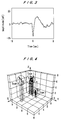
- Fig. 3 is a chart showing a template waveform of a nerve action spike.
- Fig. 4 is a diagram showing an example plot of the space-damping vectors.
- Fig. 5 is a diagram showing the result of the classification of action potential waveforms according to the present invention.
- the single-nerve-action-potential-measuring apparatus of the present invention comprises a multi-channel microelectrode, for measuring the compound nerve activity, composed of multiple bunched microelectrodes to be inserted into a brain or nerve fascicle; a space-damping-vector-calculating means, for evaluating the damping effect corresponding to the distance between the said multiple microelectrodes and nerve cells, based on the multi-channel simultaneously measured data led from the said multi-channel microelectrode, with no effect from a decrease in the signal-to-noise ratio; and a single nerve action potential separating and extracting means, for separating and extracting the nerve action potential generated from a particular neuron from other neurons, based on the space-damping vector calculated in the space-damping-vector-calculating means.
- Fig. 1 is a diagram showing an example of the constitution of the single-nerve-action-potential-measuring apparatus of the present invention.
- the single-nerve-action-potential-measuring apparatus comprises a multi-channel microelectrode 1, for measuring the compound nerve action potential, made up of multiple bunched microelectrode wires 4; amplifiers 2, for amplifying respective nerve action potentials led from the wires 4 of the multi-channel microelectrode 1; a space-damping vector-calculating section 5, and a single-nerve action potential separating and extracting section 6.
- the above multi-channel microelectrode 1, for measuring the compound nerve action potential is made up of multiple microelectrode wires 4 that are bunched and, for example, made by cutting and bunching polyurethane-covered stainless wires 4, having a diameter of 50 microns, the cut surfaces of which can be used for leading the nerve action potentials. Further, as described later, the individual electrode wires 4 serve as channels.
- the above space-damping-vector-calculating section 5 evaluates what the degree of the damping effect caused by the distance from the individual microelectrode wires 4 to the nerve cell 3 for the individual signals (outputs of the channels) outputted from the individual amplifiers 2 is, without the evaluation being affected by a decrease in the signal-to-noise ratio, and it outputs a vector having the evaluated value as an element.
- the covariances between the action potential waveforms observed from the channels and the template waveforms of nerve action potential spikes as shown in Fig. 3 are calculated, and the vectors, wherein the covariance values of the channels serve as elements, are outputted as space-damping vectors.
- the template waveforms it is preferable to use action potential waveforms that have been measured with the microelectrodes being satisfactory close to the cell, with the signal-to-noise ratio being high.
- the above single-nerve action potential separating and extracting section 6 classifies the nerve action spikes based on the space-damping vectors obtained by the space-damping-vector-calculating section 5. For example, for the action potentials, the space-damping vectors are plotted in a pseudospace, and assuming that the nerve action spikes near the values of the space-damping vectors are generated from the same nerve cell, the nerve action spikes are classified by the corresponded relationship between the place where the distribution is concentrated and the cell.
- each channel microelectrode 1 is made up of three microelectrode wires 4 (named ch1), 4 (named ch2), and 4 (named ch3), and the microelectrode 1 is inserted into a prescribed place in a brain or a nerve fascicle.
- the microelectrode 1 is inserted into a prescribed place in a brain or a nerve fascicle.
- three cells 3a, 3b, and 3c are present near the microelectrode 1.
- nerve excitation occurs, for example, in the cell 3a.
- the damping effect due to the distance between the electrode wires 4 and the cell 3 is calculated as an evaluation parameter, which is hardly affected by a decrease in the signal-to-noise ratio; that is, herein the said calculation is considered to be the covariance with the template waveform shown in Fig. 3.
- the covariance value indicates the amount of the template waveform component contained in the action potential waveform observed in the channels of wires 4 (ch1), 4 (ch2), and 4 (ch3); and in the above example, it is calculated as a large value from the action potential waveform in the first channel (ch1), and as a small value from the action potential waveform in the second channel (ch2).
- the influence that random noise or drift having waveform components different from the template waveform has on the evaluation value can be reduced.
- the thus-obtained covariance values of the individual channels are used as elements of vectors to obtain space-damping vectors.
- the space-damping vector becomes [cov (1), cov (2), cov (3)]. Since these space-damping vectors are due to the positional relationship between the cells and the microelectrodes 1, a different cell produces a different vector value.
- Fig. 4 is obtained by plotting space-damping vectors with covariance values of the waveform of the first channel (ch1) and the template waveform shown in Fig. 3, using the actually measured results assigned to be values on the x-axis, and using covariance values from the second channel (ch2) and the third channel (ch3) assigned to be values on the y-axis and z-axis, respectively. From Fig. 4, it is confirmed that the concentrated sites of space-damping vectors corresponding to the cells 3a (type 3), 3b (type 1), and 3c (type 2) are formed.
- Fig. 5 is a diagram showing the classified result of nerve action spikes by clustering the result of Fig. 4 in the single-nerve action potential separating and extracting section 6. That is, Fig. 5 shows overlapped action potential waveforms of respective types observed from individual channels of wires 4 (ch1), 4 (ch2), and 4(ch3) after clustering of types 1, 2, and 3, based on the space-damping vectors, similar to the results shown in Fig. 4. From this result, it can be understood that action potential waveforms generated from plural cells are classified for every cell. In particular, since the action potentials of the type 1 and type 3 in the third channel have almost the same waveform, they cannot be classified only by this channel information, but it is confirmed that they are classified easily by clustering by damping vectors and multi-channel measurement.
- the present invention it is possible to easily classify nerve action spikes for every cell from multiple cells present near a multi-channel microelectrode for measuring the compound nerve action potential.
- the present invention is effective for a neuroelectricity physiology experiment when the signal-to-noise ratio is low or nerve cells are densely present.
Landscapes
- Life Sciences & Earth Sciences (AREA)
- Health & Medical Sciences (AREA)
- Medical Informatics (AREA)
- Biophysics (AREA)
- Pathology (AREA)
- Engineering & Computer Science (AREA)
- Biomedical Technology (AREA)
- Heart & Thoracic Surgery (AREA)
- Physics & Mathematics (AREA)
- Molecular Biology (AREA)
- Surgery (AREA)
- Animal Behavior & Ethology (AREA)
- General Health & Medical Sciences (AREA)
- Public Health (AREA)
- Veterinary Medicine (AREA)
- Measurement And Recording Of Electrical Phenomena And Electrical Characteristics Of The Living Body (AREA)
- Apparatus Associated With Microorganisms And Enzymes (AREA)
Abstract
Description
- The present invention relates to a single-nerve-action-potential-measuring apparatus for extracting a single-neuron action potential in neuroelectricity physiology experiments.
- The technique of elucidating brain function from the nerve action potential firing pattern is utilized as a basic means in electrophysiology. In order to elucidate the brain function as executed by a nerve group, it is necessary and essential to elucidate the function of individual neurons (nerve cells), and conventionally there is the single-nerve-activity-measuring method that uses a microelectrode having a high impedance. In the single-nerve-activity-measuring method, an electrode is brought as close as possible to the target cells to be measured, to extract only the activity of a particular neuron based on the difference in the duration or the amplitude of the nerve action spike. However, under conditions when the signal-to-noise ratio is low or at a brain site where cells are densely packed (e.g., at the hippocampus), it is difficult to separate highly precisely a single nerve action spike.
- An object of the present invention is to provide a single-nerve-action-potential-measuring apparatus capable of separating and extracting the single-nerve action potential highly precisely even under conditions when the signal-to-noise ratio is low or at a brain site where cells are densely packed.
- Other and further objects, features, and advantages of the invention will appear more evident from the following description, taken in connection with the accompanying drawings.
- Fig. 1 is a diagram showing an example of the constitution of the single-nerve-action-potential-measuring apparatus of the present invention.
- Fig. 2 is a diagram illustrating the damping effect due to the distance between the microelectrode and nerve cells.
- Fig. 3 is a chart showing a template waveform of a nerve action spike.
- Fig. 4 is a diagram showing an example plot of the space-damping vectors.
- Fig. 5 is a diagram showing the result of the classification of action potential waveforms according to the present invention.
- The single-nerve-action-potential-measuring apparatus of the present invention comprises a multi-channel microelectrode, for measuring the compound nerve activity, composed of multiple bunched microelectrodes to be inserted into a brain or nerve fascicle; a space-damping-vector-calculating means, for evaluating the damping effect corresponding to the distance between the said multiple microelectrodes and nerve cells, based on the multi-channel simultaneously measured data led from the said multi-channel microelectrode, with no effect from a decrease in the signal-to-noise ratio; and a single nerve action potential separating and extracting means, for separating and extracting the nerve action potential generated from a particular neuron from other neurons, based on the space-damping vector calculated in the space-damping-vector-calculating means.
- One of the preferred embodiments of the present invention is described in more detail, with reference to the drawings.
- Fig. 1 is a diagram showing an example of the constitution of the single-nerve-action-potential-measuring apparatus of the present invention. Referring to Fig. 1, the single-nerve-action-potential-measuring apparatus comprises a
multi-channel microelectrode 1, for measuring the compound nerve action potential, made up of multiple bunchedmicroelectrode wires 4;amplifiers 2, for amplifying respective nerve action potentials led from thewires 4 of themulti-channel microelectrode 1; a space-damping vector-calculatingsection 5, and a single-nerve action potential separating and extractingsection 6. - Herein, the above
multi-channel microelectrode 1, for measuring the compound nerve action potential, is made up ofmultiple microelectrode wires 4 that are bunched and, for example, made by cutting and bunching polyurethane-coveredstainless wires 4, having a diameter of 50 microns, the cut surfaces of which can be used for leading the nerve action potentials. Further, as described later, theindividual electrode wires 4 serve as channels. - The above space-damping-vector-calculating
section 5 evaluates what the degree of the damping effect caused by the distance from theindividual microelectrode wires 4 to thenerve cell 3 for the individual signals (outputs of the channels) outputted from theindividual amplifiers 2 is, without the evaluation being affected by a decrease in the signal-to-noise ratio, and it outputs a vector having the evaluated value as an element. For example, the covariances between the action potential waveforms observed from the channels and the template waveforms of nerve action potential spikes as shown in Fig. 3 are calculated, and the vectors, wherein the covariance values of the channels serve as elements, are outputted as space-damping vectors. Herein, as the template waveforms, it is preferable to use action potential waveforms that have been measured with the microelectrodes being satisfactory close to the cell, with the signal-to-noise ratio being high. - The above single-nerve action potential separating and extracting
section 6 classifies the nerve action spikes based on the space-damping vectors obtained by the space-damping-vector-calculatingsection 5. For example, for the action potentials, the space-damping vectors are plotted in a pseudospace, and assuming that the nerve action spikes near the values of the space-damping vectors are generated from the same nerve cell, the nerve action spikes are classified by the corresponded relationship between the place where the distribution is concentrated and the cell. - Now, an example of the processing operation of the thus-constituted apparatus is described. It is assumed that each
channel microelectrode 1 is made up of three microelectrode wires 4 (named ch1), 4 (named ch2), and 4 (named ch3), and themicroelectrode 1 is inserted into a prescribed place in a brain or a nerve fascicle. At that time it is assumed that threecells microelectrode 1. Now, in Fig. 2, it is assumed that nerve excitation occurs, for example, in thecell 3a. Since thenerve cell 3a is located closest to the electrode wire 4 (ch1) of the first channel and farthest from the electrode wire 4 (ch2) of the second channel, due to the damping effect in the space, a large action potential waveform is observed in the first channel (ch1), and a small active potential waveform is observed in the second channel (ch2). These action potential waveforms; that is, the multi-channel simultaneously measured data, are amplified by theamplifiers 2 at a certain amplification rate and are inputted into the space-damping-vector-calculatingsection 5. In the space-damping-vector-calculating section, the damping effect due to the distance between theelectrode wires 4 and thecell 3 is calculated as an evaluation parameter, which is hardly affected by a decrease in the signal-to-noise ratio; that is, herein the said calculation is considered to be the covariance with the template waveform shown in Fig. 3. The covariance value indicates the amount of the template waveform component contained in the action potential waveform observed in the channels of wires 4 (ch1), 4 (ch2), and 4 (ch3); and in the above example, it is calculated as a large value from the action potential waveform in the first channel (ch1), and as a small value from the action potential waveform in the second channel (ch2). Herein, by using a typical action potential waveform as the template waveform, the influence that random noise or drift having waveform components different from the template waveform has on the evaluation value can be reduced. The thus-obtained covariance values of the individual channels are used as elements of vectors to obtain space-damping vectors. For example, in the example shown in Fig. 2, when the covariance values of the first, second, and third channels (ch1), (ch2), and (ch3) are found as cov (1), cov (2), and cov (3), respectively, the space-damping vector becomes [cov (1), cov (2), cov (3)]. Since these space-damping vectors are due to the positional relationship between the cells and themicroelectrodes 1, a different cell produces a different vector value. That is, in Fig. 2, when nerve excitement occurs in a cell different from thecell 3a -- for example, in acell 3b -- the space-damping vector is different from that obtained when nerve excitement occurs in thecell 3a. By using this, in the single-nerve action potential separating and extractingsection 6, clustering is effected, and nerve action spikes can be classified forrespective cells - Fig. 4 is obtained by plotting space-damping vectors with covariance values of the waveform of the first channel (ch1) and the template waveform shown in Fig. 3, using the actually measured results assigned to be values on the x-axis, and using covariance values from the second channel (ch2) and the third channel (ch3) assigned to be values on the y-axis and z-axis, respectively. From Fig. 4, it is confirmed that the concentrated sites of space-damping vectors corresponding to the
cells 3a (type 3), 3b (type 1), and 3c (type 2) are formed. - Fig. 5 is a diagram showing the classified result of nerve action spikes by clustering the result of Fig. 4 in the single-nerve action potential separating and extracting
section 6. That is, Fig. 5 shows overlapped action potential waveforms of respective types observed from individual channels of wires 4 (ch1), 4 (ch2), and 4(ch3) after clustering oftypes type 1 andtype 3 in the third channel have almost the same waveform, they cannot be classified only by this channel information, but it is confirmed that they are classified easily by clustering by damping vectors and multi-channel measurement. - In the above mode of operation, although this is an example in which three cells are present near the
microelectrode 1, if there are more cells near themicroelectrode 1, nerve action spikes from multiple cells can be classified for the individual cells in a similar manner. - In such a single-nerve-action-potential measuring apparatus, multiple microelectrodes are placed in the space where measurement is to be made, and the nerve action spikes are separated based on the difference in the damping effect due to the difference of the distances between the electrodes and the nerve cells. Thereby, action spikes produced from multiple nerve cells present in the space where the measurement is to be made can be separated even under conditions of a low signal-to-noise ratio or at a brain site where cells are densely present.
- As described above, according to the present invention, it is possible to easily classify nerve action spikes for every cell from multiple cells present near a multi-channel microelectrode for measuring the compound nerve action potential. The present invention is effective for a neuroelectricity physiology experiment when the signal-to-noise ratio is low or nerve cells are densely present.
- Having described our invention as related to the present embodiments, it is our intention that the invention not be limited by any of the details of the description, unless otherwise specified, but rather be construed broadly within its spirit and scope as set out in the accompanying claims.
Claims (5)
- A single-nerve-action-potential-measuring apparatus, comprising (A) a multi-channel microelectrode, for measuring the compound nerve activity, composed of multiple bunched microelectrodes to be inserted into a brain or nerve fascicle; (B) a space-damping-vector-calculating means, for evaluating the damping effect corresponding to the distance between the said multiple microelectrodes and nerve cells, based on the multi-channel simultaneously measured data led from the said multi-channel microelectrode, with no effect from a decrease in the signal-to-noise ratio; and (C) a single nerve action potential separating and extracting means, for separating and extracting the nerve action potential generated from a particular neuron from other neurons, based on the space-damping vector calculated in the space-damping-vector-calculating means.
- The single-nerve-action-potential measuring apparatus as claimed in claim 1, comprising amplifiers for amplifying respective nerve action potentials led from the multi-channel microelectrode (A).
- The single-nerve-action-potential measuring apparatus as claimed in claim 1 or 2, wherein the multi-channel microelectrode (A) comprises multiple microelectrode wires that are bunched.
- The single-nerve-action-potential-measuring apparatus as claimed in any of claims 1 to 3, wherein the space-damping-vector-calculating means (B) calculates the covariances between action potential waveforms observed from the channels and template waveforms of nerve action potential spikes, to output vectors, in which the covariance values of the channels serve as elements, as space-damping vectors.
- The single-nerve-action-potential-measuring apparatus as claimed in any of claims 1 to 4, wherein the single-nerve action potential separating and extracting means (C) classifies the nerve action spikes, by plotting in a pseudospace the space-damping vectors for the action potentials, and assuming that the nerve action spikes with the similar values of the space-damping vectors are generated from the same nerve cell, to classify the nerve action spikes by the corresponded relationship between the place where the distribution is concentrated and the cell.
Applications Claiming Priority (3)
| Application Number | Priority Date | Filing Date | Title |
|---|---|---|---|
| JP17308095 | 1995-07-10 | ||
| JP7173080A JP2736326B2 (en) | 1995-07-10 | 1995-07-10 | Single nerve action potential measurement device |
| JP173080/95 | 1995-07-10 |
Publications (3)
| Publication Number | Publication Date |
|---|---|
| EP0753284A2 true EP0753284A2 (en) | 1997-01-15 |
| EP0753284A3 EP0753284A3 (en) | 1999-03-17 |
| EP0753284B1 EP0753284B1 (en) | 2005-02-09 |
Family
ID=15953842
Family Applications (1)
| Application Number | Title | Priority Date | Filing Date |
|---|---|---|---|
| EP96111044A Expired - Lifetime EP0753284B1 (en) | 1995-07-10 | 1996-07-09 | Single-nerve-action-potential-measuring apparatus |
Country Status (4)
| Country | Link |
|---|---|
| US (1) | US5692516A (en) |
| EP (1) | EP0753284B1 (en) |
| JP (1) | JP2736326B2 (en) |
| DE (1) | DE69634319T2 (en) |
Cited By (5)
| Publication number | Priority date | Publication date | Assignee | Title |
|---|---|---|---|---|
| WO1998041145A1 (en) * | 1997-03-19 | 1998-09-24 | Arizona Board Of Regents On Behalf Of The University Of Arizona | Implantable multi-electrode microdrive array |
| ES2221528A1 (en) * | 2002-07-03 | 2004-12-16 | Universidad De Sevilla | Flexible suction electrode not requiring micromanipulators for neurophysiology, comprises an amplifier with test and reference electrodes, and a vacuum source |
| WO2007058950A3 (en) * | 2005-11-10 | 2007-08-02 | Cyberkinetics Neurotechnology | Biological interface system with neural signal classification systems and methods |
| WO2009046764A1 (en) | 2007-10-10 | 2009-04-16 | Neurotech S.A. | Neurostimulator and method for regulting the same |
| US10322281B2 (en) | 2016-11-26 | 2019-06-18 | Xialing Zhang | Adjustable angle neuro stimulation probe apapratus |
Families Citing this family (16)
| Publication number | Priority date | Publication date | Assignee | Title |
|---|---|---|---|---|
| US6330466B1 (en) * | 1998-02-23 | 2001-12-11 | California Institute Of Technology | Using a multi-electrode probe in creating an electrophysiological profile during stereotactic neurosurgery |
| AU1547101A (en) * | 1999-11-26 | 2001-06-04 | Applied Spectral Imaging Ltd. | System and method for functional brain mapping and an oxygen saturation difference map algorithm for effecting same |
| US7080188B2 (en) | 2003-03-10 | 2006-07-18 | Marvell International Ltd. | Method and system for embedded disk controllers |
| US7492545B1 (en) | 2003-03-10 | 2009-02-17 | Marvell International Ltd. | Method and system for automatic time base adjustment for disk drive servo controllers |
| US7039771B1 (en) | 2003-03-10 | 2006-05-02 | Marvell International Ltd. | Method and system for supporting multiple external serial port devices using a serial port controller in embedded disk controllers |
| US7870346B2 (en) | 2003-03-10 | 2011-01-11 | Marvell International Ltd. | Servo controller interface module for embedded disk controllers |
| US20040219184A1 (en) * | 2003-03-25 | 2004-11-04 | The Regents Of The University Of California | Growth of large patterned arrays of neurons on CCD chips using plasma deposition methods |
| JP4742356B2 (en) * | 2005-02-02 | 2011-08-10 | 独立行政法人産業技術総合研究所 | Embedded electrode device and electrode embedded device |
| US8086316B2 (en) * | 2006-05-24 | 2011-12-27 | Drexel University | Wireless controlled neuromodulation system |
| US8374673B2 (en) | 2007-01-25 | 2013-02-12 | Warsaw Orthopedic, Inc. | Integrated surgical navigational and neuromonitoring system having automated surgical assistance and control |
| US7987001B2 (en) | 2007-01-25 | 2011-07-26 | Warsaw Orthopedic, Inc. | Surgical navigational and neuromonitoring instrument |
| KR101912165B1 (en) | 2011-12-09 | 2018-10-29 | 삼성전자주식회사 | Neural working memory |
| JP2015181347A (en) * | 2014-03-20 | 2015-10-22 | Cyberdyne株式会社 | Nerve cell culture method and transplantation module |
| CN104367314B (en) * | 2014-11-05 | 2017-07-14 | 中国科学院深圳先进技术研究院 | Electrode assembly for carrying out acute record |
| US10576268B2 (en) * | 2017-03-22 | 2020-03-03 | International Business Machines Corporation | High resolution brain-electronics interface |
| JP6991622B1 (en) * | 2021-04-21 | 2022-01-14 | 株式会社メルティンMmi | Methods, systems, and electrode structures for acquiring electrical signals from multiple nerves in a living body, and methods for manufacturing the electrode structures. |
Family Cites Families (9)
| Publication number | Priority date | Publication date | Assignee | Title |
|---|---|---|---|---|
| SU650610A1 (en) * | 1977-03-03 | 1979-03-05 | Институт Высшей Нервной Деятельности И Нейрофизиологии Ан Ссср | Device for examining brain neurons |
| JPS59160440A (en) * | 1983-03-03 | 1984-09-11 | 工業技術院長 | Muscle action measuring apparatus by multi-point measurementof muscle potential |
| JPS59200632A (en) * | 1983-04-26 | 1984-11-14 | 工業技術院長 | Apparatus for detecting nerve muscle junction distribution by muscle potential multi-point measurement |
| US4603703A (en) * | 1984-04-13 | 1986-08-05 | The Board Of Trustees Of The Leland Stanford Junior University | Method for real-time detection and identification of neuroelectric signals |
| JPS61217136A (en) * | 1985-03-20 | 1986-09-26 | 工業技術院長 | Apparatus for measuring muscle fiber conducting speed |
| JPS6397147A (en) * | 1986-10-15 | 1988-04-27 | 松下電工株式会社 | Sleep onset determination device |
| US5178161A (en) * | 1988-09-02 | 1993-01-12 | The Board Of Trustees Of The Leland Stanford Junior University | Microelectronic interface |
| JP3179196B2 (en) * | 1991-08-06 | 2001-06-25 | 三菱電機株式会社 | Estimation of connection structure between neurons |
| US5563067A (en) * | 1994-06-13 | 1996-10-08 | Matsushita Electric Industrial Co., Ltd. | Cell potential measurement apparatus having a plurality of microelectrodes |
-
1995
- 1995-07-10 JP JP7173080A patent/JP2736326B2/en not_active Expired - Lifetime
-
1996
- 1996-07-09 EP EP96111044A patent/EP0753284B1/en not_active Expired - Lifetime
- 1996-07-09 DE DE69634319T patent/DE69634319T2/en not_active Expired - Fee Related
- 1996-07-10 US US08/677,847 patent/US5692516A/en not_active Expired - Fee Related
Non-Patent Citations (1)
| Title |
|---|
| None |
Cited By (8)
| Publication number | Priority date | Publication date | Assignee | Title |
|---|---|---|---|---|
| US5928143A (en) * | 1996-03-29 | 1999-07-27 | Arizona Board Of Regents On Behalf Of The University Of Arizona | Implantable multi-electrode microdrive array |
| WO1998041145A1 (en) * | 1997-03-19 | 1998-09-24 | Arizona Board Of Regents On Behalf Of The University Of Arizona | Implantable multi-electrode microdrive array |
| ES2221528A1 (en) * | 2002-07-03 | 2004-12-16 | Universidad De Sevilla | Flexible suction electrode not requiring micromanipulators for neurophysiology, comprises an amplifier with test and reference electrodes, and a vacuum source |
| WO2007058950A3 (en) * | 2005-11-10 | 2007-08-02 | Cyberkinetics Neurotechnology | Biological interface system with neural signal classification systems and methods |
| WO2009046764A1 (en) | 2007-10-10 | 2009-04-16 | Neurotech S.A. | Neurostimulator and method for regulting the same |
| US9248274B2 (en) | 2007-10-10 | 2016-02-02 | Sorin Crm Sas | Neurostimulator and method for regulating same |
| US10342980B2 (en) | 2007-10-10 | 2019-07-09 | Sorin Crm Sas | Neurostimulator and method for regulating the same |
| US10322281B2 (en) | 2016-11-26 | 2019-06-18 | Xialing Zhang | Adjustable angle neuro stimulation probe apapratus |
Also Published As
| Publication number | Publication date |
|---|---|
| EP0753284B1 (en) | 2005-02-09 |
| EP0753284A3 (en) | 1999-03-17 |
| US5692516A (en) | 1997-12-02 |
| JPH0924031A (en) | 1997-01-28 |
| DE69634319T2 (en) | 2006-04-06 |
| DE69634319D1 (en) | 2005-03-17 |
| JP2736326B2 (en) | 1998-04-02 |
Similar Documents
| Publication | Publication Date | Title |
|---|---|---|
| EP0753284B1 (en) | Single-nerve-action-potential-measuring apparatus | |
| JP4875696B2 (en) | Method and apparatus for suppressing interference in electromagnetic multi-channel measurements | |
| Forster et al. | Automatic classification and analysis of microneurographic spike data using a PC/AT | |
| Sayer et al. | Amplitude fluctuations in small EPSPs recorded from CA1 pyramidal cells in the guinea pig hippocampal slice | |
| Møller | Dynamic properties of primary auditory fibers compared with cells in the cochlear nucleus | |
| Suarez et al. | Modeling direction selectivity of simple cells in striate visual cortex within the framework of the canonical microcircuit | |
| Versnel et al. | Spectral-ripple representation of steady-state vowels in primary auditory cortex | |
| EP0355506A1 (en) | Arrangement for measuring local bioelectric currents in biological tissue | |
| Nádasdy et al. | Extracellular recording and analysis of neuronal activity: from single cells to ensembles | |
| Sahani et al. | On the separation of signals from neighboring cells in tetrode recordings | |
| DE10110724A1 (en) | Fingerprint sensor with potential modulation of the ESD protective grid | |
| Schreiner et al. | Temporal processing in cat primary auditory cortex | |
| DE19927616A1 (en) | Method and device for distinguishing between electromagnetic interference signals and electromedical scanning signals, in particular of cardiological implants | |
| Louage et al. | Decorrelation sensitivity of auditory nerve and anteroventral cochlear nucleus fibers to broadband and narrowband noise | |
| Oshurkova et al. | Click train encoding in primary and non-primary auditory cortex of anesthetized macaque monkeys | |
| Sanderson et al. | Selectivity for echo spectral interference and delay in the auditory cortex of the big brown bat Eptesicus fuscus | |
| Mellinger et al. | A method for filtering bioacoustic transients by spectrogram image convolution | |
| Knudsen | Midbrain units in catfish: response properties to electroreceptive input | |
| JP3931238B2 (en) | Nerve cell action potential classifier and its classification program | |
| Glenn et al. | Effects of visual attention on the latency of auditory evoked potentials | |
| Astrelin et al. | Principal component analysis of minimal excitatory postsynaptic potentials | |
| Mohammadi et al. | Data reduction for real-time enhanced growing neural gas spike sorting with multiple recording channels | |
| Ogata et al. | Mode of activation of pyramidal neurons by mossy fiber stimulation in thin hippocampal slices in vitro | |
| Tessadori et al. | Encoding of stimuli in embodied neuronal networks | |
| Donaldson et al. | Velocity-selective recording using multi-electrode nerve cuffs |
Legal Events
| Date | Code | Title | Description |
|---|---|---|---|
| PUAI | Public reference made under article 153(3) epc to a published international application that has entered the european phase |
Free format text: ORIGINAL CODE: 0009012 |
|
| AK | Designated contracting states |
Kind code of ref document: A2 Designated state(s): DE FR GB |
|
| PUAL | Search report despatched |
Free format text: ORIGINAL CODE: 0009013 |
|
| AK | Designated contracting states |
Kind code of ref document: A3 Designated state(s): DE FR GB |
|
| 17P | Request for examination filed |
Effective date: 19990401 |
|
| GRAP | Despatch of communication of intention to grant a patent |
Free format text: ORIGINAL CODE: EPIDOSNIGR1 |
|
| GRAS | Grant fee paid |
Free format text: ORIGINAL CODE: EPIDOSNIGR3 |
|
| GRAA | (expected) grant |
Free format text: ORIGINAL CODE: 0009210 |
|
| AK | Designated contracting states |
Kind code of ref document: B1 Designated state(s): DE FR GB |
|
| REG | Reference to a national code |
Ref country code: GB Ref legal event code: FG4D |
|
| REF | Corresponds to: |
Ref document number: 69634319 Country of ref document: DE Date of ref document: 20050317 Kind code of ref document: P |
|
| PG25 | Lapsed in a contracting state [announced via postgrant information from national office to epo] |
Ref country code: GB Free format text: LAPSE BECAUSE OF NON-PAYMENT OF DUE FEES Effective date: 20050709 |
|
| ET | Fr: translation filed | ||
| PLBE | No opposition filed within time limit |
Free format text: ORIGINAL CODE: 0009261 |
|
| STAA | Information on the status of an ep patent application or granted ep patent |
Free format text: STATUS: NO OPPOSITION FILED WITHIN TIME LIMIT |
|
| 26N | No opposition filed |
Effective date: 20051110 |
|
| PG25 | Lapsed in a contracting state [announced via postgrant information from national office to epo] |
Ref country code: DE Free format text: LAPSE BECAUSE OF NON-PAYMENT OF DUE FEES Effective date: 20060201 |
|
| GBPC | Gb: european patent ceased through non-payment of renewal fee |
Effective date: 20050709 |
|
| REG | Reference to a national code |
Ref country code: FR Ref legal event code: ST Effective date: 20080229 |
|
| PG25 | Lapsed in a contracting state [announced via postgrant information from national office to epo] |
Ref country code: FR Free format text: LAPSE BECAUSE OF NON-PAYMENT OF DUE FEES Effective date: 20050731 |