EP0752702A1 - Canal de lecture d'un réseau neuronal artificiel - Google Patents
Canal de lecture d'un réseau neuronal artificiel Download PDFInfo
- Publication number
- EP0752702A1 EP0752702A1 EP96106025A EP96106025A EP0752702A1 EP 0752702 A1 EP0752702 A1 EP 0752702A1 EP 96106025 A EP96106025 A EP 96106025A EP 96106025 A EP96106025 A EP 96106025A EP 0752702 A1 EP0752702 A1 EP 0752702A1
- Authority
- EP
- European Patent Office
- Prior art keywords
- neuron
- signal
- output
- layer
- neurons
- Prior art date
- Legal status (The legal status is an assumption and is not a legal conclusion. Google has not performed a legal analysis and makes no representation as to the accuracy of the status listed.)
- Granted
Links
Images


Classifications
-
- G—PHYSICS
- G11—INFORMATION STORAGE
- G11B—INFORMATION STORAGE BASED ON RELATIVE MOVEMENT BETWEEN RECORD CARRIER AND TRANSDUCER
- G11B20/00—Signal processing not specific to the method of recording or reproducing; Circuits therefor
- G11B20/10—Digital recording or reproducing
- G11B20/10009—Improvement or modification of read or write signals
- G11B20/10481—Improvement or modification of read or write signals optimisation methods
- G11B20/10518—Improvement or modification of read or write signals optimisation methods using neural networks
-
- G—PHYSICS
- G11—INFORMATION STORAGE
- G11B—INFORMATION STORAGE BASED ON RELATIVE MOVEMENT BETWEEN RECORD CARRIER AND TRANSDUCER
- G11B20/00—Signal processing not specific to the method of recording or reproducing; Circuits therefor
- G11B20/10—Digital recording or reproducing
- G11B20/10009—Improvement or modification of read or write signals
-
- G—PHYSICS
- G11—INFORMATION STORAGE
- G11B—INFORMATION STORAGE BASED ON RELATIVE MOVEMENT BETWEEN RECORD CARRIER AND TRANSDUCER
- G11B5/00—Recording by magnetisation or demagnetisation of a record carrier; Reproducing by magnetic means; Record carriers therefor
- G11B5/02—Recording, reproducing, or erasing methods; Read, write or erase circuits therefor
- G11B5/09—Digital recording
-
- H—ELECTRICITY
- H04—ELECTRIC COMMUNICATION TECHNIQUE
- H04L—TRANSMISSION OF DIGITAL INFORMATION, e.g. TELEGRAPHIC COMMUNICATION
- H04L25/00—Baseband systems
- H04L25/02—Details ; arrangements for supplying electrical power along data transmission lines
- H04L25/03—Shaping networks in transmitter or receiver, e.g. adaptive shaping networks
- H04L25/03006—Arrangements for removing intersymbol interference
- H04L25/03165—Arrangements for removing intersymbol interference using neural networks
-
- H—ELECTRICITY
- H04—ELECTRIC COMMUNICATION TECHNIQUE
- H04L—TRANSMISSION OF DIGITAL INFORMATION, e.g. TELEGRAPHIC COMMUNICATION
- H04L7/00—Arrangements for synchronising receiver with transmitter
- H04L7/02—Speed or phase control by the received code signals, the signals containing no special synchronisation information
-
- H—ELECTRICITY
- H04—ELECTRIC COMMUNICATION TECHNIQUE
- H04L—TRANSMISSION OF DIGITAL INFORMATION, e.g. TELEGRAPHIC COMMUNICATION
- H04L25/00—Baseband systems
- H04L25/02—Details ; arrangements for supplying electrical power along data transmission lines
- H04L25/03—Shaping networks in transmitter or receiver, e.g. adaptive shaping networks
- H04L25/03006—Arrangements for removing intersymbol interference
- H04L2025/03433—Arrangements for removing intersymbol interference characterised by equaliser structure
- H04L2025/03439—Fixed structures
- H04L2025/03445—Time domain
- H04L2025/03464—Neural networks
-
- H—ELECTRICITY
- H04—ELECTRIC COMMUNICATION TECHNIQUE
- H04L—TRANSMISSION OF DIGITAL INFORMATION, e.g. TELEGRAPHIC COMMUNICATION
- H04L7/00—Arrangements for synchronising receiver with transmitter
- H04L7/0054—Detection of the synchronisation error by features other than the received signal transition
- H04L7/0062—Detection of the synchronisation error by features other than the received signal transition detection of error based on data decision error, e.g. Mueller type detection
-
- H—ELECTRICITY
- H04—ELECTRIC COMMUNICATION TECHNIQUE
- H04L—TRANSMISSION OF DIGITAL INFORMATION, e.g. TELEGRAPHIC COMMUNICATION
- H04L7/00—Arrangements for synchronising receiver with transmitter
- H04L7/04—Speed or phase control by synchronisation signals
- H04L7/10—Arrangements for initial synchronisation
Definitions
- the present invention is directed to read channels used in magnetic recording technology, and more particularly to an artificial neural network read channel for performing detection, filtering, equalization, and clock recovery reconstruction of a signal from magnetic media.
- a typical read channel for a magnetic recording system comprises an electromagnetic read/write head having means for detecting the magnetic fields stored by the particles on the magnetic media and for converting the received electromagnetic signals to electronic signals.
- a preamplifier then receives the electronic signal from the electromagnetic read/write head, which is typically in the mV range, and amplifies it typically to the hundreds of mV range.
- a filter/equalizer receives the amplified signal from the preamplifier to equalize the channel response and filter out unwanted noise.
- the output from the equalizer is level qualified and peak detected yielding a digital pulse train which is phase locked and then decoded.
- modulation codes e.g., on-off, polar, or bipolar codes.
- Modulation codes are characterized by, among other properties, adequate timing content, intersymbol interference (ISI), error detection and correction capability, favorable power spectral density, and transparency (yielding correct data transmission regardless of pattern of 0's and 1's).
- ISI intersymbol interference
- error detection and correction capability e.g., error detection and correction capability
- favorable power spectral density e.g., power spectral density
- transparency yielding correct data transmission regardless of pattern of 0's and 1's.
- the modulation code used in magnetic read channels for magnetic recording systems is typically based on a bipolar signal, which utilized the nonlinear magnetic characteristics of the media.
- An alternative way of viewing the signal processing problem is to recognize that there exist a finite number of possible expected data values (or patterns) recorded on the media.
- the problem may then be treated as a pattern recognition, or classification, problem.
- methods have been developed for use in pattern recognition.
- One such method is to employ an artificial neural network.
- An artificial neural network also called a neural net, is a dense interconnection of simple computational elements operating in parallel and connected by links of variable weights to solve a problem and to achieve high performance pattern recognition.
- Neural nets are known to be generally noise immune (especially when trained with noisy data), capable of a certain amount of generalization, and capable of deductively handling perturbations in the data to correctly classify the data.
- each computational element also called a node or neuron, receives a number of weighted inputs, performs a summation of the inputs, and passes the output of the summer through a non-linearity (and possibly a bias for limiting the output swing).
- the neurons are typically arranged in layers and are interconnected by a set of weights associated with each summer.
- a neural network typically involves a learning process and a generalization process, or application.
- a training algorithm adjusts the weights of the neurons to produce a trained network, whereby it correctly responds to as many randomly preselected patterns as possible in a training set containing the desired responses.
- the neural net may be tested by applying input patterns which were not included in the training set. If the trained network correctly responds with high probability to the applied input test patterns, the neural network has been generalized, and is ready for application.
- the neural network would typically be trained, generalized, and installed in the application device during the manufacturing process.
- the artificial neural network approach also allows circumvention of timing extraction issues. Utilizing the non-linear relationships in the signal itself as the training reference, the neural net can provide a "trained" timing response to the input data from which the synchronization signal may be derived.
- a neural network is employed in the magnetic read channel of the present invention to reconstruct (or "classify") a recorded magnetic signal and to extract the synchronization signal from the data itself.
- the use of neural networks in a magnetic read channel has the advantage of adaptability because neural networks can have the capability of training new or altered input.
- an artificial neural network read channel for use in a magnetic recording system.
- the invention as described herein may comprise a magnetic read channel having an artificial neural network performing the equivalent of filtering, equalization, reconstruction, and detection of a magnetic signal received from a magnetic read head.
- a magnetic read head receives magnetic signals from a magnetic recording media such as a magnetic tape or disk and converts it to an electronic signal.
- a preamplifier receives and amplifies the electronic signal from the magnetic read head to produce an amplified electronic signal.
- a delay line receives the amplified electronic signal from the preamplifier and stores delayed successive representations of the amplified electronic signal.
- An artificial neural network receives the delayed successive representations of the signal from the delay line for reconstruction of the originally recorded data signal.
- a set of first layer artificial neurons each receives the stored delayed representations of the amplified electronic signal from the delay line, performs a weighted summation of the delayed representations, and passes the sum through a non-linearity to produce first input layer output signals.
- a set of second hidden layer artificial neurons each receives the first layer output signals as input, performs a weighted summation of the inputs, and passes the sum through a non-linearity to produce second hidden layer output signals.
- a set of third output layer artificial neurons each receives the second layer output signals as input, performs a weighted summation of the inputs, and passes the sum through a non-linearity to produce both the reconstructed data signal and the reconstructed synchronization signal from the signal originally recorded on the magnetic media.
- Reconstruction is accomplished via a prior conducted training process which utilizes a training set of known data and clock pairs to determine the optimum neuron weight set values for proper reconstruction (or classification) of both the data and synchronization signals.
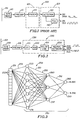
- FIG. 1 shows a block diagram of a standard read channel for a magnetic recording device.
- Traditional read channels generally comprise three stages, including filter/equalization 102, detection 103, and reconstruction of the signal.
- a standard read channel 100 as FIG. 1 depicts, generally includes a magnetic read head 110 for receiving the magnetic signals from the magnetic recording media 101 and converting the magnetic signals to electronic signals.
- a preamplifier 115 typically receives the electronic signal from the magnetic read head 110 and amplifies the electronic signal to produce an amplified electronic signal with a signal-to-noise ratio suitable for input to a filter 120.
- a filter 120 typically a lowpass filter, receives the amplified electronic signal and removes undesirable noise from the signal.
- a detector 130 receives the filtered signal to derive the data from the analog read signal and restore it to a pulse stream.
- a phase locked loop 140 is used to synchronize the pulse stream and facilitate data recovery.
- FIG. 2 shows the block diagram of the read channel 200 of the present invention.
- an artificial neural network stage 220 replaces the filter/equalization 102 and detection 103 stages of the traditional magnetic read channel.
- a magnetic read head 210 receives a magnetic signal from the magnetic recording media 201 and converts the magnetic signal to an electronic signal.
- a preamplifier 215 receives the electronic signal from the magnetic read head 210 and amplifies it to produce an amplified electronic signal having a level of suitable signal-to-noise ratio for input to subsequent circuitry.
- An artificial neural network stage 220 then receives the amplified electronic signal for equalization, detection and reconstruction of the original data signal recorded on the magnetic recording media 201 to produce a reconstructed data signal 295 and a reconstructed synchronization signal 296.
- the preferred embodiment depicted in FIG. 2 is implemented for use with digital data, it will be appreciated that the present invention is not limited to digital data implementations; rather, the output will be dependent on the implementation of the artificial neural network stage 220. Thus, if the neural network implementation is digital, the output will be discrete. If the neural network implementation is analog, the output will be continuous.
- the preferred embodiment is constructed as a digital neural network for use with digital data.
- a sample-and-hold circuit 221 samples the amplified electronic signal periodically, holding constant the level of the signal until the next sample, thereby quantizing the signal in preparation for analog-to-digital conversion.
- An analog-to-digital (A/D) converter 222 receives the quantized signal and converts it to a digital signal which is equivalent to the quantized analog input signal.
- a delay line 251 receives the converted digital signal from the A/D converter 222 for delaying and storing successive representations of the digital signal.
- a neural network 250 receives the delayed successive representations of the digital signal from the delay line 251 for reconstruction of the data signal 295 and the synchronization signal 296.
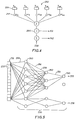
- FIG. 3 depicts the delay line 251 and the neural network 250 of the preferred embodiment in greater detail.
- the neural network 250 used in the preferred embodiment is implemented using a feedforward fully interconnected neural network topology having a 7-3-2 configuration 290.
- the delay line 251 delays and stores successive representations of the delayed signal in a series of delay line taps 252, wherein each delay line tap 252 contains one delayed representation of the input signal.
- Each delay line tap 252 is directly coupled to each artificial neuron 260 in the first layer 291.
- Each artificial neuron 260 has the capability of receiving a plurality of inputs 259 and producing an output signal 261 which is a nonlinear weighted combination of its inputs 259.
- FIG. 4 depicts a typical artificial neuron 260 coupled with a non-linearity 264.
- the network topology implemented in the preferred embodiment is a 7-3-2 feedforward configuration 290, comprising a first "input" layer 291 having seven neurons, a second "hidden” layer 292 having three neurons, and a third "output” layer 293 having two neurons.
- the neural network is fully interconnected, having each neuron in a given layer connected to every neuron in the subsequent layer.
- the output layer 293 produces a reconstructed data signal 295 and a reconstructed synchronization signal 296 (which is reconstructed directly from the input data itself).
- FIG. 5 An alternative preferred embodiment of the network topology is shown in FIG. 5.
- the reconstructed data signal 295 is derived from a feedforward neural network.
- the synchronization output 296 is derived from a sparsely connected neural network.
- FIG. 6 illustrates the application of the training algorithm 500 to the neural network 250.
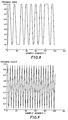
- a training set 505 is generated containing an input data signal 506 from the magnetic read head (shown in FIG. 10) and corresponding pairs of training data and clock (synchronization) signals 507 (shown in FIG. 8 and 9).
- the input data signal 506 of the training set 505 is used as the input to the neural network 250.
- the input data signal 506 itself contains a representation of the clock signal. However, the clock signal is hidden within the data and may only be extracted through nonlinear means.
- the artificial neural network is ideal for solving the problem of extracting the hidden synchronization signal from the data signal because it can be trained using the nonlinear characteristics hidden in the data signal itself.
- the input data signal 506 is applied as the inputs 259 of the neurons 260 in the first layer 291.
- the input data signal 506 (FIG. 10) is propagated through the second layer 292 and third layer 293 to produce an output response pair 508, which, once the network is trained, also represents the reconstructed data signal 295 (FIG. 11) and the reconstructed synchronization signal 296 (FIG. 12).
- the output response pair 508 is compared to the desired response pair 507 (FIG. 8 and 9) to produce an error signal 509.
- a training algorithm 500 accordingly adjusts the weights via the weight vector W k 257 for each artificial neuron 260 in the first layer 291 to minimize the error between the output response 508 and the desired response 507.
- the input training data is reapplied iteratively until the network converges, and the weight values are optimized.
- the preferred embodiment employs backpropagation 510 for the training method 500.
- the backpropagation training method 510 is an iterative gradient algorithm designed to minimize the mean square error between the actual output of a multilayer feed-forward neural network and the desired output.
- Each first layer neuron receives the input data signal 506 (FIG. 10) at its inputs X k 259, weights the inputs 259 via the weight vector W k 257, performs a summation of its weighted inputs, and passes the sum through a non-linearity to produce an output signal 261.
- Each second layer neuron receives the output signals 261 from the first layer neurons as input 259, performs a weighted summation and passes the sum through a non-linearity to produce an output signal 261.
- Each third layer neuron receives the output signals 261 from the second layer neurons as input 259, performs a weighted summation and passes the sum through a non-linearity to produce an output response 508.
- Step 3 523 the error signal is calculated using the output response 508 and the desired response 507. Since the neural network 250 can only generate an output from 0 to 1, all desired response data is typically set between 0.1 and 0.9.
- the error signal is calculated by one of two methods, namely by either cumulative cycle error or by squared error.
- Step 4 524 depicted in FIG. 7B, the weight vectors W k 257 are adapted recursively, starting at the third output layer neurons 293 and working back to the first input layer neurons 291.
- the weights are adapted according to the backpropagation algorithm as given in Step 4 524 of FIG. 7B.
- Steps 2 through 4 (522 through 524) of the backpropagation algorithm given in FIG. 7A and 7B are repeated until generalization occurs.
- Generalization occurs when the network output mean squared error for an epoch (one pass through a training set 505) is less than the training goal, E max .
- the neural network 250 is trained, and may be tested using input test data.
- Appendices A1-A9 depict the actual implementation of the preferred embodiment.
- the neural network 250 in the preferred embodiment employed the widely used commercially available interactive mathematical computation environment, MATLAB, produced by Mathworks, Inc., for implementing the feedforward 7-3-2 configuration neural network 290 and the backpropagation training algorithm 510.
- Appendix A1 is a sample control file for initializing the network topology, the learning rate for each layer, the number of iterations to perform in which convergence should occur, and a momentum value to speed up convergence.
- the neural network topology of the preferred embodiment has a 7-3-2 configuration 290.
- the learning rates, represented by the variables u1, u2, and u3, are set to .1, .25, and .4 for the first, second and third layers, respectively.
- the momentum, which affects the learning process is set to .95.
- the implementation for generating the training set 505 including the corresponding pairs of desired responses 507, and the input data vectors X_n 506, is depicted in Appendix A2.
- the training set 505, D_n_set contains a set of corresponding data and clock signals.
- a random subset of the training set 505 is selected.
- the input vector comprises 25 randomly selected consecutive samples of the input data signal 506, with its center point aligned with the 2 points selected for the output vector.
- the two output vector points correspond to the data (FIG. 9) and clock (FIG. 8) signals of the desired response 507.
- Each of the 50 vector pairs makes a single pass, called an epoch, through the training algorithm 500.
- the data is randomly reselected, and the process repeats.
- the mean squared error is usually acceptable.
- the neural network 250 can be reset and retrained, or the configuration can be modified by adding or subtracting artificial neurons 260. For the preferred embodiment as described herein, the neural network 250 converges consistently.
- Appendix A3 is the MATLAB implementation for selecting a random input data signal 506 and desired response 507 pair from the training set 505.
- Appendix A4 depicts the weight initialization file in which the weight vectors W k 257 for each layer, represented by the variables w1, w2, and w3, are initialized with small random values. Appendix A4 corresponds to algorithm Step 1 521 in FIG. 7A. Appendix A5 is the MATLAB implementation for loading the network configuration and parameters into the MATLAB environment.
- the implementation of the backpropagation training 510 of the neural network 250 is depicted in Appendix A6-A7.
- lines 38-39 of Appendix A6-A7 random noise is added to the input data signal 506, X_n, for use in training the neural network 250.
- Lines 45-47 of Appendix A6-A7 correspond to backpropagation algorithm Step 2 522 in FIG. 7A in which the output response o k 261 for each artificial neuron 260 is calculated.
- Lines 48-49 of Appendix A6-A7 correspond to backpropagation algorithm Step 3 523 in FIG. 7A, wherein the error is calculated.
- Lines 50-63 in Appendix A6-A7 correspond to backpropagation algorithm Step 4 524 in FIG. 7B, wherein the backpropagation actually occurs and the weights 257 are adjusted.
- Appendix A9 depicts the implementation of the test simulation and calculation of the mean square error per epoch.
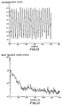
- the test simulation program is used after the neural network 250 has been trained via the backpropagation algorithm 510 of FIG. 7A and 7B and its implementation in Appendix A6-A7. With the network configuration parameters set in Appendix A1, the neural network 250 of the preferred embodiment converged, as illustrated by the decreasing mean square error depicted in FIG. 13.
- FIG. 8 and 9 show plots of the training data and training clock, corresponding to the desired response 507 in FIG. 6, used for training the artificial neural network in the preferred embodiment.
- FIG. 10 shows a plot of the signal from the magnetic read head used as the input data set for the artificial neural network after it has been trained.
- FIG. 11 and 12 show plots of the reconstructed data (295) and clock (296) in the preferred embodiment.
- FIG. 13 shows a plot of the mean squared error achieved in the preferred embodiment.
- Backpropagation 510 employed as the training method 500 for a feedforward neural network topology was the subject of the preferred embodiment.
- neural networks 250 may be built using many different configurations and training algorithms 500.
- the feedforward neural network of the preferred embodiment need not be fully interconnected.
- FIG. 5 illustrates an alternative preferred embodiment neural network configuration 290 in which the synchronization signal 296 is reconstructed from a sparsely connected neural network.
- the number of layers and number of artificial neurons 260 per layer may be varied (although it is generally accepted that any pattern recognition or classification problem can be solved using only three layers).
- the feedforward network topology may be replaced with an unsupervised Hopfield network or a Hamming network; alternatively, it may be replaced with an unsupervised Kohonen self-organizing feature map.
- the algorithm 500 used in training the neural network is by no means limited to backpropagation 510.
- the algorithm chosen to train the neural network 250 most often depends on the structure and configuration of the neural network 250.
- both the Hopfield network and the Hamming network utilize training algorithms 500 specific to their networks.
- the nature and spirit of the invention is to utilize a neural network to replace the detection, equalization, and reconstruction stages of a traditional magnetic read channel 100, which encompasses various means for building and training a neural network 250.
Landscapes
- Engineering & Computer Science (AREA)
- Signal Processing (AREA)
- Computer Networks & Wireless Communication (AREA)
- Artificial Intelligence (AREA)
- Evolutionary Computation (AREA)
- Power Engineering (AREA)
- Signal Processing For Digital Recording And Reproducing (AREA)
- Digital Magnetic Recording (AREA)
Applications Claiming Priority (2)
| Application Number | Priority Date | Filing Date | Title |
|---|---|---|---|
| US499152 | 1995-07-07 | ||
| US08/499,152 US5699487A (en) | 1995-07-07 | 1995-07-07 | Artificial neural network read channel |
Publications (2)
| Publication Number | Publication Date |
|---|---|
| EP0752702A1 true EP0752702A1 (fr) | 1997-01-08 |
| EP0752702B1 EP0752702B1 (fr) | 2001-09-19 |
Family
ID=23984060
Family Applications (1)
| Application Number | Title | Priority Date | Filing Date |
|---|---|---|---|
| EP96106025A Expired - Lifetime EP0752702B1 (fr) | 1995-07-07 | 1996-04-17 | Canal de lecture d'un réseau neuronal artificiel |
Country Status (4)
| Country | Link |
|---|---|
| US (1) | US5699487A (fr) |
| EP (1) | EP0752702B1 (fr) |
| JP (1) | JPH09120642A (fr) |
| DE (1) | DE69615293T2 (fr) |
Cited By (1)
| Publication number | Priority date | Publication date | Assignee | Title |
|---|---|---|---|---|
| WO2001001344A3 (fr) * | 1999-06-26 | 2002-03-21 | Axeon Ltd | Reseau neuronal servant a effectuer une egalisation de voie en temps reel |
Families Citing this family (15)
| Publication number | Priority date | Publication date | Assignee | Title |
|---|---|---|---|---|
| US5978782A (en) * | 1996-07-05 | 1999-11-02 | National Semiconductor Corporation | Neural network signal processor for magnetic storage channels |
| US5845646A (en) * | 1996-11-05 | 1998-12-08 | Lemelson; Jerome | System and method for treating select tissue in a living being |
| JPH11273254A (ja) | 1998-03-20 | 1999-10-08 | Toshiba Corp | ディスク記憶装置 |
| TW418383B (en) * | 1998-09-23 | 2001-01-11 | Ind Tech Res Inst | Telephone voice recognition system and method and the channel effect compensation device using the same |
| DE60142582D1 (de) * | 2000-10-13 | 2010-08-26 | Fraunhofer Ges Forschung | Verfahren zum überwachten trainieren eines iterativen künstlichen neuronalen netzwerks |
| US7133233B1 (en) | 2000-10-24 | 2006-11-07 | Maxtor Corporation | Disk drive with read while write capability |
| DE10316381A1 (de) * | 2003-04-10 | 2004-10-28 | Bayer Technology Services Gmbh | Verfahren zum Training von neuronalen Netzen |
| US7362892B2 (en) | 2003-07-02 | 2008-04-22 | Lockheed Martin Corporation | Self-optimizing classifier |
| US11113800B2 (en) * | 2017-01-18 | 2021-09-07 | Nvidia Corporation | Filtering image data using a neural network |
| US11080621B2 (en) | 2018-06-18 | 2021-08-03 | Western Digital Technologies, Inc. | Machine learning-based read channel data detection |
| US11495248B2 (en) * | 2020-06-23 | 2022-11-08 | Fujifilm Corporation | Signal processing device, magnetic tape cartridge, magnetic tape reading apparatus, processing method of signal processing device, operation method of magnetic tape reading apparatus, and non-transitory computer-readable storage medium |
| JP7358420B2 (ja) * | 2020-06-23 | 2023-10-10 | 富士フイルム株式会社 | 信号処理装置、磁気テープカートリッジ、磁気テープ読取装置、信号処理装置の処理方法、磁気テープ読取装置の動作方法、及びプログラム |
| JP2022045663A (ja) * | 2020-09-09 | 2022-03-22 | 株式会社東芝 | 磁気ディスク装置及びリード処理方法 |
| US11811425B2 (en) | 2021-05-18 | 2023-11-07 | Western Digital Technologies, Inc. | Neural network soft information detector in a read channel |
| US11646059B2 (en) * | 2021-08-30 | 2023-05-09 | Seagate Technology Llc | Estimating read offset in a drive using machine learning |
Citations (4)
| Publication number | Priority date | Publication date | Assignee | Title |
|---|---|---|---|---|
| EP0454445A2 (fr) * | 1990-04-26 | 1991-10-30 | Fujitsu Limited | Egalisateur de formes d'ondes utilisant un réseau de neurones |
| EP0498574A2 (fr) * | 1991-01-31 | 1992-08-12 | Victor Company Of Japan, Limited | Dispositif d'égalisation de forme d'onde constitué par un réseau neuronal et procédé de réalisation |
| JPH0562365A (ja) * | 1991-09-03 | 1993-03-12 | Fujitsu Ltd | 磁気記録再生装置の復調方法 |
| JPH05307622A (ja) * | 1992-04-28 | 1993-11-19 | Victor Co Of Japan Ltd | 波形等化装置 |
Family Cites Families (3)
| Publication number | Priority date | Publication date | Assignee | Title |
|---|---|---|---|---|
| US5151970A (en) * | 1990-07-02 | 1992-09-29 | General Electric Company | Method of generating, in the analog regime, weighted summations of digital signals |
| US5247605A (en) * | 1990-07-02 | 1993-09-21 | General Electric Company | Neural nets supplied synapse signals obtained by digital-to-analog conversion of plural-bit samples |
| US5594597A (en) * | 1991-11-01 | 1997-01-14 | Iomega Corporation | Neural network disk drive read channel pattern detector |
-
1995
- 1995-07-07 US US08/499,152 patent/US5699487A/en not_active Expired - Fee Related
-
1996
- 1996-04-17 DE DE69615293T patent/DE69615293T2/de not_active Expired - Fee Related
- 1996-04-17 EP EP96106025A patent/EP0752702B1/fr not_active Expired - Lifetime
- 1996-06-25 JP JP8164037A patent/JPH09120642A/ja active Pending
Patent Citations (4)
| Publication number | Priority date | Publication date | Assignee | Title |
|---|---|---|---|---|
| EP0454445A2 (fr) * | 1990-04-26 | 1991-10-30 | Fujitsu Limited | Egalisateur de formes d'ondes utilisant un réseau de neurones |
| EP0498574A2 (fr) * | 1991-01-31 | 1992-08-12 | Victor Company Of Japan, Limited | Dispositif d'égalisation de forme d'onde constitué par un réseau neuronal et procédé de réalisation |
| JPH0562365A (ja) * | 1991-09-03 | 1993-03-12 | Fujitsu Ltd | 磁気記録再生装置の復調方法 |
| JPH05307622A (ja) * | 1992-04-28 | 1993-11-19 | Victor Co Of Japan Ltd | 波形等化装置 |
Non-Patent Citations (4)
| Title |
|---|
| BASSAI H J ET AL: "Artificial neural networks for smart detection of digitally modulated signals", 1994 IEEE GLOBECOM. COMMUNICATIONS: THE GLOBAL BRIDGE. CONFERENCE RECORD (CAT. NO.94CH34025), 1994 IEEE GLOBECOM. COMMUNICATIONS: THE GLOBAL BRIDGE, SAN FRANCISCO, CA, USA, 28 NOV.-2 DEC. 1994, ISBN 0-7803-1820-X, 1994, NEW YORK, NY, USA, IEEE, USA, pages 1029 - 1033 vol.2, XP000488693 * |
| NAIR S K ET AL: "Improved equalization for digital recording using nonlinear filtering and error confinement", SIXTH JOINT MAGNETISM AND MAGNETIC MATERIALS - INTERNATIONAL MAGNETICS CONFERENCE, ALBUQUERQUE, NM, USA, 20-23 JUNE 1994, vol. 30, no. 6, pt.1, ISSN 0018-9464, IEEE TRANSACTIONS ON MAGNETICS, NOV. 1994, USA, pages 4221 - 4223, XP000562574 * |
| PATENT ABSTRACTS OF JAPAN vol. 017, no. 384 (P - 1575) 19 July 1993 (1993-07-19) * |
| PATENT ABSTRACTS OF JAPAN vol. 018, no. 121 (P - 1700) 25 February 1994 (1994-02-25) * |
Cited By (1)
| Publication number | Priority date | Publication date | Assignee | Title |
|---|---|---|---|---|
| WO2001001344A3 (fr) * | 1999-06-26 | 2002-03-21 | Axeon Ltd | Reseau neuronal servant a effectuer une egalisation de voie en temps reel |
Also Published As
| Publication number | Publication date |
|---|---|
| US5699487A (en) | 1997-12-16 |
| DE69615293D1 (de) | 2001-10-25 |
| EP0752702B1 (fr) | 2001-09-19 |
| JPH09120642A (ja) | 1997-05-06 |
| DE69615293T2 (de) | 2002-06-27 |
Similar Documents
| Publication | Publication Date | Title |
|---|---|---|
| US5699487A (en) | Artificial neural network read channel | |
| CN112418014B (zh) | 基于小波变换和卷积长短期记忆神经网络的调制信号识别方法 | |
| Cha et al. | Channel equalization using adaptive complex radial basis function networks | |
| US6052349A (en) | Waveform equalizer and memory device having a waveform equalizer | |
| KR100265501B1 (ko) | 자기 저장 채널을 위한 뉴럴 네트워크 신호 처리기 | |
| EP0498574B1 (fr) | Dispositif d'égalisation de forme d'onde constitué par un réseau neuronal et procédé de réalisation | |
| Stornetta et al. | A dynamical approach to temporal pattern processing | |
| WO1996017309A1 (fr) | Systeme de traitement de signaux aveugles utilisant la maximalisation des informations pour recuperer des signaux inconnus par une minimalisation non supervisee de la redondance de sortie | |
| De Veciana et al. | Neural net-based continuous phase modulation receivers | |
| Ong et al. | A decision feedback recurrent neural equalizer as an infinite impulse response filter | |
| EP0749123B1 (fr) | Détection de symboles à vraisemblance maximale pour des données codées RLL | |
| Sayyafan et al. | Deep neural network media noise predictor turbo-detection system for 1-D and 2-D high-density magnetic recording | |
| Nair et al. | Data storage channel equalization using neural networks | |
| US6335913B1 (en) | Disk memory device and disk read-out signal processor | |
| US5594597A (en) | Neural network disk drive read channel pattern detector | |
| Lu et al. | Channel equalization by feedforward neural networks | |
| Fiori | Analysis of modified" Bussgang" algorithms (MBAs) for channel equalization | |
| Siu et al. | Decision feedback equalization using neural network structures | |
| Czyzewski | Some methods for detection and interpolation of impulsive distortions in old audio recordings | |
| JPH08101819A (ja) | 歪みデータ信号の等化方法および回路装置 | |
| Grant | Artificial neural network and conventional approaches to filtering and pattern recognition | |
| Nanda et al. | Development of novel digital equalizers for noisy nonlinear channel using artificial immune system | |
| Barua | Neural networks and their applications to computer data security | |
| JP2722941B2 (ja) | ニューラルネットによる波形処理装置の学習設計方法 | |
| JP3003711B2 (ja) | 磁気記録再生装置の復調器 |
Legal Events
| Date | Code | Title | Description |
|---|---|---|---|
| PUAI | Public reference made under article 153(3) epc to a published international application that has entered the european phase |
Free format text: ORIGINAL CODE: 0009012 |
|
| 17P | Request for examination filed |
Effective date: 19960812 |
|
| AK | Designated contracting states |
Kind code of ref document: A1 Designated state(s): DE FR GB |
|
| 17Q | First examination report despatched |
Effective date: 20000208 |
|
| GRAG | Despatch of communication of intention to grant |
Free format text: ORIGINAL CODE: EPIDOS AGRA |
|
| GRAG | Despatch of communication of intention to grant |
Free format text: ORIGINAL CODE: EPIDOS AGRA |
|
| GRAG | Despatch of communication of intention to grant |
Free format text: ORIGINAL CODE: EPIDOS AGRA |
|
| GRAH | Despatch of communication of intention to grant a patent |
Free format text: ORIGINAL CODE: EPIDOS IGRA |
|
| RAP1 | Party data changed (applicant data changed or rights of an application transferred) |
Owner name: HEWLETT-PACKARD COMPANY, A DELAWARE CORPORATION |
|
| GRAH | Despatch of communication of intention to grant a patent |
Free format text: ORIGINAL CODE: EPIDOS IGRA |
|
| GRAA | (expected) grant |
Free format text: ORIGINAL CODE: 0009210 |
|
| AK | Designated contracting states |
Kind code of ref document: B1 Designated state(s): DE FR GB |
|
| REF | Corresponds to: |
Ref document number: 69615293 Country of ref document: DE Date of ref document: 20011025 |
|
| REG | Reference to a national code |
Ref country code: GB Ref legal event code: IF02 |
|
| ET | Fr: translation filed | ||
| PLBE | No opposition filed within time limit |
Free format text: ORIGINAL CODE: 0009261 |
|
| STAA | Information on the status of an ep patent application or granted ep patent |
Free format text: STATUS: NO OPPOSITION FILED WITHIN TIME LIMIT |
|
| 26N | No opposition filed | ||
| PGFP | Annual fee paid to national office [announced via postgrant information from national office to epo] |
Ref country code: GB Payment date: 20050413 Year of fee payment: 10 |
|
| PGFP | Annual fee paid to national office [announced via postgrant information from national office to epo] |
Ref country code: FR Payment date: 20050418 Year of fee payment: 10 |
|
| PGFP | Annual fee paid to national office [announced via postgrant information from national office to epo] |
Ref country code: DE Payment date: 20050531 Year of fee payment: 10 |
|
| PG25 | Lapsed in a contracting state [announced via postgrant information from national office to epo] |
Ref country code: GB Free format text: LAPSE BECAUSE OF NON-PAYMENT OF DUE FEES Effective date: 20060417 |
|
| PG25 | Lapsed in a contracting state [announced via postgrant information from national office to epo] |
Ref country code: DE Free format text: LAPSE BECAUSE OF NON-PAYMENT OF DUE FEES Effective date: 20061101 |
|
| GBPC | Gb: european patent ceased through non-payment of renewal fee |
Effective date: 20060417 |
|
| REG | Reference to a national code |
Ref country code: FR Ref legal event code: ST Effective date: 20061230 |
|
| PG25 | Lapsed in a contracting state [announced via postgrant information from national office to epo] |
Ref country code: FR Free format text: LAPSE BECAUSE OF NON-PAYMENT OF DUE FEES Effective date: 20060502 |