EP0751629B1 - Carrying means for attachment device for mobile station - Google Patents
Carrying means for attachment device for mobile station Download PDFInfo
- Publication number
- EP0751629B1 EP0751629B1 EP96660019A EP96660019A EP0751629B1 EP 0751629 B1 EP0751629 B1 EP 0751629B1 EP 96660019 A EP96660019 A EP 96660019A EP 96660019 A EP96660019 A EP 96660019A EP 0751629 B1 EP0751629 B1 EP 0751629B1
- Authority
- EP
- European Patent Office
- Prior art keywords
- guide grooves
- carrying means
- tongue
- mobile station
- plane
- Prior art date
- Legal status (The legal status is an assumption and is not a legal conclusion. Google has not performed a legal analysis and makes no representation as to the accuracy of the status listed.)
- Expired - Lifetime
Links
- 239000013013 elastic material Substances 0.000 claims description 6
- 238000010276 construction Methods 0.000 description 5
- 238000005452 bending Methods 0.000 description 1
- 238000004519 manufacturing process Methods 0.000 description 1
- 239000000463 material Substances 0.000 description 1
- 239000002184 metal Substances 0.000 description 1
- 238000000034 method Methods 0.000 description 1
- 238000006748 scratching Methods 0.000 description 1
- 230000002393 scratching effect Effects 0.000 description 1
Images
Classifications
-
- H—ELECTRICITY
- H04—ELECTRIC COMMUNICATION TECHNIQUE
- H04B—TRANSMISSION
- H04B1/00—Details of transmission systems, not covered by a single one of groups H04B3/00 - H04B13/00; Details of transmission systems not characterised by the medium used for transmission
- H04B1/38—Transceivers, i.e. devices in which transmitter and receiver form a structural unit and in which at least one part is used for functions of transmitting and receiving
- H04B1/3827—Portable transceivers
- H04B1/3833—Hand-held transceivers
-
- A—HUMAN NECESSITIES
- A45—HAND OR TRAVELLING ARTICLES
- A45F—TRAVELLING OR CAMP EQUIPMENT: SACKS OR PACKS CARRIED ON THE BODY
- A45F5/00—Holders or carriers for hand articles; Holders or carriers for use while travelling or camping
- A45F5/02—Fastening articles to the garment
-
- A—HUMAN NECESSITIES
- A45—HAND OR TRAVELLING ARTICLES
- A45F—TRAVELLING OR CAMP EQUIPMENT: SACKS OR PACKS CARRIED ON THE BODY
- A45F5/00—Holders or carriers for hand articles; Holders or carriers for use while travelling or camping
- A45F5/1516—Holders or carriers for portable handheld communication devices, e.g. pagers or smart phones
-
- Y—GENERAL TAGGING OF NEW TECHNOLOGICAL DEVELOPMENTS; GENERAL TAGGING OF CROSS-SECTIONAL TECHNOLOGIES SPANNING OVER SEVERAL SECTIONS OF THE IPC; TECHNICAL SUBJECTS COVERED BY FORMER USPC CROSS-REFERENCE ART COLLECTIONS [XRACs] AND DIGESTS
- Y10—TECHNICAL SUBJECTS COVERED BY FORMER USPC
- Y10T—TECHNICAL SUBJECTS COVERED BY FORMER US CLASSIFICATION
- Y10T24/00—Buckles, buttons, clasps, etc.
- Y10T24/13—Article holder attachable to apparel or body
- Y10T24/1394—Article held by clip
-
- Y—GENERAL TAGGING OF NEW TECHNOLOGICAL DEVELOPMENTS; GENERAL TAGGING OF CROSS-SECTIONAL TECHNOLOGIES SPANNING OVER SEVERAL SECTIONS OF THE IPC; TECHNICAL SUBJECTS COVERED BY FORMER USPC CROSS-REFERENCE ART COLLECTIONS [XRACs] AND DIGESTS
- Y10—TECHNICAL SUBJECTS COVERED BY FORMER USPC
- Y10T—TECHNICAL SUBJECTS COVERED BY FORMER US CLASSIFICATION
- Y10T24/00—Buckles, buttons, clasps, etc.
- Y10T24/45—Separable-fastener or required component thereof [e.g., projection and cavity to complete interlock]
- Y10T24/45225—Separable-fastener or required component thereof [e.g., projection and cavity to complete interlock] including member having distinct formations and mating member selectively interlocking therewith
- Y10T24/45602—Receiving member includes either movable connection between interlocking components or variable configuration cavity
- Y10T24/45623—Receiving member includes either movable connection between interlocking components or variable configuration cavity and operator therefor
- Y10T24/4566—Receiving member includes either movable connection between interlocking components or variable configuration cavity and operator therefor including slidably connected and guided element on receiving member
Definitions
- the invention relates to a carrying means for an attachment device which is used together with a mobile station and with which the mobile station can be attached to a target and removed from the place of attachment and re-attached to it, when said attachment device comprises: a support stud connected to a mobile phone and a carrying means attached to a target with an attachment element, said carrying means including gripping elements for the detachable grip on the support stud.
- the attachment device comprises e.g. a carrying means to be fastened to a belt and a support stud attached to the mobile station with a fitting piece.
- the carrying means includes gripping elements formed of guide grooves to receive the support stud, and the support stud has a wider end consisting of a flange which reaches said gripping elements before the body part.
- the gripping elements in the carrying means also include a spring-loaded tongue which yields when a mobile station is pushed into the carrying means an when it is pulled out from the carrying means. While this method of operation is quick and easy, it involves the risk that if the mobile station is unintentionally pushed, e.g. when its user sits down, it comes off inadvertently and may fall.
- An object of the invention is to provide a carrying means for a mobile station attachment device like the one described above, which reliably holds a mobile station attached to it so that the mobile station will not come off even if it were pushed with strength.
- a second object of the invention is to provide such a carrying means, wherein the attachment and detachment of a mobile phone is easy and quick in spite of the attachment reliability mentioned above.
- a third object of the invention is to provide such a carrying means, which is simple in construction and simple and economical to manufacture.
- An object of the invention is particularly to provide a carrying means for an attachment device which can be attached to the clothing of the person carrying it and which allows the mobile station to turn with respect to the point of attachment and with which the mobile station can be attached to another target, such as a rack or the like in a car or elsewhere.
- the invention will be described with the assumption that the mobile station is a phone attached to the user's belt. It is clear that the carrying means according to the invention can also be used in conjunction with other mobile stations, such as paging devices, and it can be attached to other garments as well, e.g. to the waist of a skirt or trousers, the brim of a pocket etc.; to the brim of a bag or to other locations in these items and to other appropriate targets, such as parts, devices or equipment or the like in a vehicle or elsewhere. To that end, the carrying means in question is attached to the target in an appropriate way.
- the attachment device to which the invention relates, comprises two parts: an attachment device carrying means, which remains on the belt when the phone is being used, and a support stud attached to the phone with a fitting piece.
- the phone is locked onto the belt and detached from it by means of a locking tongue. While on the belt, the phone can be turned around the axis of the support stud when necessary, whereby the user can, e.g. when sitting, easily turn the phone forward or backward around the axis of the support stud so that the phone will not press the user's waist.
- the phone can easily be removed from the belt by pushing down the slide in the attachment device carrying means attached to the belt and at the same time lifting the phone up.
- the construction according to the invention facilitates easy removal of the phone from the belt without breaking or scratching the belt or the phone.
- the user When attaching the phone to the belt, the user only has to push the phone down to the carrying means of the attachment device, whereby the phone is locked to the body part by means of a locking tongue acting in a spring-like manner and an inward-bent flange-like edge circling the body part.
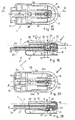
- the figures describe a carrying means 1 for the attachment device of a mobile station 10, with which the mobile station can be attached to the user's belt or other garment and, when necessary, removed from that place and re-attached to it.
- the attachment device of the mobile station comprises, firstly, the carrying means I shown in the figures and attached to the user's clothing and having gripping elements to receive the support stud 2 of a mobile station.
- the dashed-and-dotted line depicts part of a mobile station and the support stud 2 attached to it.
- the carrying means 1 has on three sides 3a, 3b and 3c inward-opening guide grooves 8 which are located on one plane 4 and which are formed by the channels between the edges 28 and the carrying means body 25, the channels of the two opposite sides 3a and 3c being parallel to each other and the third channel of side 3b in the middle transverse to the other two.
- On the fourth side 3d of the carrrying means there is no guide groove, whereby the flange on the end of the support stud 2 can be pushed from the fourth side 3d into the guide grooves 8 in the direction 11 of the plane 4 of the guide grooves.
- the support stud 2 can be removed from the guide grooves when the locking, which will be discussed below, has been removed in the release position R.
- the support stud has a circular flange 9 in the guide grooves 8 or the support stud can revolve about its mounting axis, it can rotate and allows the mobile station to turn when needed.
- a tongue 7 which is pushed into the support stud prevents the mobile station from being detached from the carrying means.
- the support stud 2 is attached to the mobile station in any practical manner not described in this document.
- the carrying means includes a tongue 7 or a corresponding element which moves transversely to the plane 4 of the guide grooves 8.
- this tongue 7 When this tongue 7 is in the locking position L shown in Figs. 1A and 1B, it protrudes across the plane 4 of the guide grooves and thus into the hollow 33 in the middle of the outer end of the flange 9 on the end of the support stud.
- this tongue 7 prevents the support stud 2 from being removed from the guide grooves 8 in direction 11 when the tongue is in the locking position L.
- a spring 13 exerts a force F against said tongue 7 so that the latter stays in the locking position L extending across the plane of the guide grooves.
- the carrying means 1 includes a slide 27 which moves parallely to the plane 4 of the guide grooves and contains a transfer element 12 to force the tongue 7 against the spring force F so that it comes off the position extending across the plane of the guide grooves.
- Figs. 2A and 2B illustrate a situation in which the slide 27 has forced the tongue 7 away from the plane 4 of the guide grooves, and particularly away from the plane for a distance corresponding to the height of the guide grooves, whereby the guide grooves 8 and the area between them are completely free from obstacles, which enables the free removal of the support stud and its flanges from the carrying means.
- the tongue 7 is in the release position R, which releases the support stud 2 and which according to the invention is brought about by means of the slide 27, pressed in direction P by the user.
- the slide can be made to move in another direction than that of the plane of the guide grooves; say, transversely to that plane 4.
- the slide 27 moves in the carrying means body 25 in a direction of the guide groove plane 4.
- An advantageous direction P is identical with direction 11 along which the support stud 2 of a mobile station is brought to the guide grooves 8 and removed from them. It is also possible to have the slide 27 move in another direction, say, transversely to said moving direction 11 of the support stud.
- the embodiments shown in the figures employ the advantageous embodiment mentioned above, because then it is easy to press the slide on its applying end 24 in direction P while the mobile station 10 is attached to the carrying means.
- the slide 27 includes a transfer element 12 comprising a wedge surface 16 which is located on that side of the slide which faces away from the plane of the guide grooves.
- the thinner edge 21 of the wedge surface 16 is located away from the applying end 24 of the slide and the thicker edge 22 of the wedge surface 16 is located closer to the applying end 24 of the slide. So, the wedge surface constitutes a wedge-shaped element in the slide in the preferred embodiment of the invention.
- the transfer element 12 comprises as continuations of the thinner edge 21 of the wedge surface 16 straighter projections 23 which rest against the sliding surface 26 of the tongue 7 when the tongue is in the locking position L. This is to ensure that the wedge surface 16 is all the time in contact with one surface only to achieve operational reliability.
- the wedge element and thus the wedge surface 16, or, to be more precise, the thicker edge 22 of the wedge surface is located at a distance 19, in the direction P of the movement of the slide, from the tongue 7, or, to be more precise, from the parts of the tongue 7 that interact with the wedge surface 16.
- a spring 13 can freely press the tongue 17 into the locking position L without being prevented by the transfer element.
- the wedge surface 16 of the transfer element has forced the tongue to move away from the plane of the guide grooves in a direction transverse to the plane 4 of the guide grooves, for a distance corresponding to the difference in the thickness of the thinner edge 21 and thicker edge 22 of the wedge, as can be clearly seen from Fig. 2B.
- the guide grooves 8 are free, as described above.
- the transfer element 12 may be considerably different from what has been described above. Especially if the slide moves in a direction other than that of the plane 4 of the guide grooves, the transfer element is of another type than the wedge-shaped piece described above. In general, it can be said that the transfer element is any construction part or shaped item of a construction part in the carrying means that can move the tongue 7 or a corresponding element against a spring force F into the release position R when pressed by the user. Thus, the transfer element may also be an appendage or a shape in the tongue.
- the tongue 7 may be a separate piece 17 that can move against the plane 4 of the guide grooves, directed by transverse guiding surfaces 18, as shown in the figures.
- the tongue may be a piece attached to a spring or to the free end of the spring slip shown in the figures, whereby the movement of the spring guides it against the plane 4 of the guide grooves in the transverse direction.
- the tongue 7 may also be a projection shaped in the spring or in the spring slip shown in the figures, composed of the material of said spring or spring slip.
- the tongue piece 17 or a corresponding projection is located on that side of the spring or spring plate 14 that faces the guide grooves 8.
- the separate piece 17 constituting the tongue 7 is substantially T-shaped, whereby the vertical branch of the T-shape constitutes those edges 30 and 31 of the tongue 7 that extend across the plane 4 of the guide grooves.
- the horizontal branch of the T-shape is located in the direction of the plane 4 of the guide grooves on that side of the wedge surfaces 16 of the slide that is facing away from the plane 4 of the guide grooves, as can be clearly understood from Figs. 1B and 2B.
- These horizontal branches of the T-shape contain sliding surfaces 26 against which the wedge surfaces 16 are pressed to move the tongue 7 against a spring force, from the locking position L to the release position R.
- the portion constituting the transfer element 12 in the slide 27 has two branches, namely, branches 32a and 32b which extend across the two sides of the vertical branch of the T-shape to press the two sliding surfaces 26 of the horizontal branch of the T-shape.
- the spring 13 that presses the tongue 7 to the locking position L extending across the plane 4 of the guide grooves can be of any suitable type.
- a bending spring made of a plate 14 of a suitable elastic material, like metal, and located mainly parallel to the plane 4 of the guide grooves, as shown in the figures.
- This plate 14 is fixed by its edges to the body 25 of the carrying means, thereby constituting the rear surface of the carrying means facing away from the guide grooves 8.
- a slip 15 is formed in this plate 14 of an elastic material by means of cut-outs 33a,b thus creating a sufficiently long and suitably flexible shape that has a spring force F which holds the tongue 7 in its locking position L, and yet the tongue 7 can be moved away from the locking position into the release position R with a relatively light movement of the slide 27. So, particularly, the tongue 7 is formed in the free end 20 of the spring slip 15 or this free end 20 presses a tongue formed of a separate piece 17, as shown in the figures.
- said spring formed of a plate 14 continues in the form of a U-bend away from slip 15, whereby it, being long enough, constitutes an attachment plate 5 for the carrying means, with which the carrying means can be attached to a belt or other location in the clothes.
- the carrying means can be attached to the clothes in other ways, too.
- the applying end 24 of the slide is thus located on the carrying means' side 3d that has no guide groove, as is the U-bend of the elastic-material plate 14.
- the attachment plate 5 of the carrying means can of course be of quite a different type and be composed of fasteners of types required in each particular case.
- the attachment plate can be a multipurpose fastener and/or it can be replaceable, for example.
- two of those edges of the tongue 7 that extend across the plane 4 of the guide grooves 8 are shaped in a special manner.
- One edge 30 of the tongue on the side of the side 3d without a guide groove is bevelled such that, relative to the guide groove plane, it forms an angle of incidence K, which is over 90° and typically in the range of 120 to 150°. Because of this, there is no need to use the slide 27 when pushing the support stud 2 of a mobile station into the guide grooves 8, but the support stud flange 9 presses the bevelled edge 30 and thus the tongue 7 against a spring force F, enabling the support stud to be pressed into the locking position, wherein the spring 13 presses the tongue 7 into the locking hollow 33 in the support stud.
- a second edge 31 of the tongue on the side of the middle side 3b having a guide groove 8 is shaped substantially perpendicular to the guide groove plane 4, whereby pushing the mobile station and thus forcing the support stud 2 in direction 11 does not make the tongue 7 move against the spring force but, in order to release the support stud one has to use the slide 27 as described above.
- the edges of the locking hollow 33 in the support stud are approximately perpendicular to the guide groove plane 4, whereby, when the mobile station is inadvertently pushed, these surfaces transverse to plane 4 meet and the tongue 7 does not yield.
Landscapes
- Engineering & Computer Science (AREA)
- Computer Networks & Wireless Communication (AREA)
- Signal Processing (AREA)
- Telephone Set Structure (AREA)
Description
- Fig. 1A
- shows the carrying means according to the invention as seen from above, in direction I of Fig. 1B, through the attachment plate, and the means in the locking position. The support stud of the mobile station is represented by a dashed-and-dotted line.
- Fig. 1B
- is a profile drawing of the carrying means of Fig. 1A along plane II-II with the means in the locking position. The support stud of the mobile station is represented by a dashed-and-dotted line.
- Fig. 2A
- shows the carrying means according to the invention as seen from above in the same direction as in Fig. 1A, through the attachment plate and the means in the detachment position.
- Fig. 2B
- is a profile drawing of the carrying means according to the invention in the same direction as in Fig. 1B and the means in the detachment position, corresponding to the functional status shown in Fig. 2A.
Claims (8)
- A carrying means for an attachment device which is used together with a mobile station and with which the mobile station can be attached to a target and detached from the place of attachment and re-attached to it, the attachment device comprising: a support stud (2) attached to a mobile station (10) and a carrying means (1) attached to a target by means of an attachment element (5), including gripping elements for the detachable grip on the support stud, wherein the gripping elements of the carrying means (1) comprise guide grooves (8) to receive a support stud (2) and a tongue (7) or a corresponding element moving against the plane (4) of the guide grooves in the transverse direction, characterized in that said tongue (7) or corresponding element is held by a spring (13) in the locking position (L) extending across the plane of the guide grooves, and that the carrying means (1) also includes a moving slide (27) which has a transfer element (12) to force the tongue against a spring force (F) off the position extending across the plane of the guide grooves, into the release position (R) that releases the support stud (2) when the user presses (P) the slide.
- A carrying means for a mobile station according to claim 1, characterized in that the spring (13) is substantially formed of a slip (15) of a plate (14) of an elastic material and parallel to the guide grooves, pressing said tongue with its free end (20) into the locking position, and that the tongue (7) is either a separate piece (17) moving against the plane of the guide grooves, guided by transverse guiding surfaces (18), or, alternatively, the tongue is a piece attached to the free end of the spring slip or a projection shaped in the free end of the spring slip, whereby said pieces and correspondingly the projection are located on that side of the plate (14) which faces the guide grooves (8).
- A carrying means for a mobile station according to claim 1, characterized in that, in the locking position (L) of the slide, the transfer element (12) of the slide (27) is located at a distance (19) away from the tongue (7), in the direction of the guide grooves, and the transfer element comprises a wedge surface (16) that faces away from the plane of the guide grooves and the thinner edge (21) of which is located away from the applying end (24) of the slide, and that the tongue or spring includes a sliding surface (26) on the side of the guide grooves against which the wedge surface (16) of the transfer element rests and that in the release position (R) of the slide the thicker edge (22) of the wedge surface is pressed against said sliding surface (26), whereby the tongue (7) is removed from the position extending across the plane of the guide grooves.
- A carrying means for a mobile station according to claim 1, characterized in that the transfer element (12) includes, as a continuation of the thinner edge (21) of the wedge surface, a straighter projection (23) which rests against a sliding surface (26), and that the applying end (24) of the slide is located on that carrying means' side (3d) which has no guide groove and is located opposite to the middle one of the three guide grooves, and that the slide moves parallel to the two extreme guide grooves (8/3a, 8/3c), guided by the guiding surfaces in the carrying means (1).
- A carrying means for a mobile station according to claim 2, characterized in that the plate (14) which is of an elastic material and constitutes a spring (13) is attached by its edges to the carrying means body (25) which includes the guide grooves, thereby forming the rear surface of the carrying means facing away from the guide grooves (8), and that the plate (14) which is of an elastic material continues as a U-bend, constituting the attachment plate (5) of the carrying means.
- A carrying means for a mobile station according to any one of the preceding claims, characterized in that the guide grooves (8) are open to the inside on three opposite sides (3a to 3c) for said reception of a support stud in the direction of the plane (4) of the guide grooves, and that there is a flange (9) at the end of the support stud (2) to be pushed into the guide grooves and a locking hollow for the tongue (7) or the like for its locking position (L), and that the slide (27) advantageously moves parallel to the plane (4) of the guide grooves.
- A carrying means for a mobile station according to any one of the preceding claims, characterized in that of those edges of the tongue (7) that extend across the plane (4) of the guide grooves, a first edge (30) of the tongue on the side of the side (3d) with no guide groove is bevelled and a second edge (31) of the tongue on the side of the middle guide groove (8/3b) is substantially perpendicular to the plane (4) of the guide grooves, and that, relative to the guide groove plane, said bevelled edge forms an angle of incidence (K) which is over 90°.
- A carrying means for a mobile station according to any one of the preceding claims, characterized in that the target, to which the mobile station (10) is attached, is a person's clothing, such as a belt, the brim of a pocket or an accessory or the like or, alternatively, a part, device or equipment or the like in a vehicle or elsewhere, and that the carrying means (1) in question is attached to the target.
Applications Claiming Priority (2)
| Application Number | Priority Date | Filing Date | Title |
|---|---|---|---|
| FI953247 | 1995-06-30 | ||
| FI953247A FI107850B (en) | 1995-06-30 | 1995-06-30 | Carrier for attachment of mobile telephony device |
Publications (3)
| Publication Number | Publication Date |
|---|---|
| EP0751629A2 EP0751629A2 (en) | 1997-01-02 |
| EP0751629A3 EP0751629A3 (en) | 2001-05-09 |
| EP0751629B1 true EP0751629B1 (en) | 2002-10-16 |
Family
ID=8543709
Family Applications (1)
| Application Number | Title | Priority Date | Filing Date |
|---|---|---|---|
| EP96660019A Expired - Lifetime EP0751629B1 (en) | 1995-06-30 | 1996-05-27 | Carrying means for attachment device for mobile station |
Country Status (4)
| Country | Link |
|---|---|
| US (1) | US5779115A (en) |
| EP (1) | EP0751629B1 (en) |
| DE (1) | DE69624290D1 (en) |
| FI (1) | FI107850B (en) |
Families Citing this family (29)
| Publication number | Priority date | Publication date | Assignee | Title |
|---|---|---|---|---|
| DK9600128U3 (en) * | 1996-04-12 | 1997-08-08 | Laugesen Lise Lotte | Holder for recording a barely fitted object |
| FI104927B (en) | 1997-10-02 | 2000-04-28 | Nokia Mobile Phones Ltd | Mobile station |
| FI104928B (en) | 1997-11-27 | 2000-04-28 | Nokia Mobile Phones Ltd | Wireless communication means and method of manufacturing a wireless communication means |
| GB2331866B (en) | 1997-11-28 | 2001-08-29 | Nokia Mobile Phones Ltd | Radiotelephone |
| FI980303A7 (en) * | 1998-02-10 | 1999-08-11 | Nokia Corp | Packaging |
| FI980603L (en) * | 1998-03-18 | 1999-09-19 | Nokia Mobile Phones Ltd | Hinged electronic device |
| KR200189787Y1 (en) * | 1998-06-12 | 2000-08-01 | 김동주 | Holder of portable cordless phone |
| EP1101373A1 (en) * | 1998-08-07 | 2001-05-23 | Amtel Technology Pty. Ltd. | Attachment device for mobile phone |
| US5979019A (en) * | 1998-12-22 | 1999-11-09 | Johnson; Desline Taylor | Adjustable belt clip construction |
| US6233788B1 (en) * | 1999-11-23 | 2001-05-22 | Motorola Inc. | Integrally molded clip and clip assembly |
| GB2364737A (en) * | 2000-07-11 | 2002-02-06 | Mouchet Nokes Victor Arthur De | Belt clip with resiliently reinforced tongue |
| US6786372B2 (en) * | 2001-09-07 | 2004-09-07 | Clip Technology, Inc. | Belt clip apparatus for portable electronic device |
| US20040251286A1 (en) * | 2002-06-26 | 2004-12-16 | Paul Badillo | Belt clip and locking fastener for selectively securing an electronic device |
| US20050035164A1 (en) * | 2002-06-26 | 2005-02-17 | Paul Badillo | Belt clip and locking fastener for selectively securing an electronic device |
| US20040232180A1 (en) * | 2003-05-19 | 2004-11-25 | Paul Badillo | Belt clip and locking fastener for selectively securing an electronic device |
| US20040069821A1 (en) * | 2002-10-10 | 2004-04-15 | Masatoshi Kobayashi | Rotating detachable belt clip |
| US7032791B2 (en) * | 2003-10-01 | 2006-04-25 | The Clip Company | All plastic clip |
| US20050173482A1 (en) * | 2004-02-10 | 2005-08-11 | Paul Badillo | Clip for an electronic case |
| US20050284904A1 (en) * | 2004-06-29 | 2005-12-29 | Knapp Christopher J | Attachment for portable electronic devices and methods for using the same |
| US20050284903A1 (en) * | 2004-06-29 | 2005-12-29 | Knapp Christopher J | Attachment for portable electronic devices and methods for using the same |
| US20070215659A1 (en) * | 2006-03-17 | 2007-09-20 | Knapp Christopher J | Connector for portable devices and methods for using the same |
| ES2357449T3 (en) * | 2007-09-13 | 2011-04-26 | Modelabs Group Sa | HANGING DEVICE OF A WIRELESS TELEPHONE COMMUNICATION DEVICE, SUCH AS A MOBILE PHONE OR A HANDS-FREE EAR PHONE. |
| US20090260191A1 (en) * | 2008-04-18 | 2009-10-22 | Cornelison Finnian Grey | Belt loop securing device, and related methods |
| US8122520B2 (en) * | 2009-03-16 | 2012-02-28 | Jaco Athletics, Llc | Lower-body garment having a secure waist assembly |
| US20100242239A1 (en) * | 2009-03-24 | 2010-09-30 | Gathering Storm Llc Dba Tmax Gear | Fastening Mechanism |
| DE102010011464A1 (en) * | 2010-03-15 | 2011-09-15 | Fresenius Medical Care Deutschland Gmbh | Blood treatment device |
| US20190382162A1 (en) * | 2018-06-19 | 2019-12-19 | Levgo | Surface-mounting Holding Device |
| CN113382661B (en) | 2019-02-12 | 2023-06-20 | 米沃奇电动工具公司 | Tool Attachment System |
| CN112294196B (en) * | 2020-10-31 | 2021-11-16 | 澧县星香源物业服务有限公司 | Intelligent household cleaning and dust removing equipment based on local area network |
Family Cites Families (23)
| Publication number | Priority date | Publication date | Assignee | Title |
|---|---|---|---|---|
| US231048A (en) * | 1880-08-10 | Fastener for carriage-aprons | ||
| US982298A (en) * | 1909-06-10 | 1911-01-24 | Alexander J Pollock | Clasp or holder. |
| US1022663A (en) * | 1910-04-18 | 1912-04-09 | Jacob Ehmann | Clasp. |
| US1395627A (en) * | 1919-12-10 | 1921-11-01 | John T Binkley | Fastening device |
| US2954951A (en) * | 1959-01-26 | 1960-10-04 | Viewlex Inc | Slide lock mounting means |
| US4419794A (en) * | 1981-10-05 | 1983-12-13 | Repco Incorporated | Portable fastening device |
| SE454740B (en) * | 1984-01-13 | 1988-05-30 | Geypa Gmbh & Co Kg | BELT BELT, SEPARATELY FOR THE CAR BELT |
| FR2632166B1 (en) * | 1988-06-02 | 1990-09-21 | Ecia Equip Composants Ind Auto | CONDEMNATION BUCKLE FOR SEAT BELT |
| FI85783C (en) * | 1989-02-17 | 1992-05-25 | Nokia Mobira Oy | Cooling construction for transistor |
| US5265158A (en) * | 1989-05-25 | 1993-11-23 | Nokia Mobile Phones Ltd. | Construction of a stand alone portable telephone unit |
| FI85203C (en) * | 1990-04-12 | 1992-03-10 | Nokia Mobile Phones Ltd | Internal handset for handset |
| FI85204C (en) * | 1990-04-12 | 1992-03-10 | Nokia Mobile Phones Ltd | KONSTRUKTION FOER RADIOTELEFON ELLER MANOEVERANORDNING TILL EN RADIOTELEFON. |
| FI88230C (en) * | 1990-04-12 | 1993-04-13 | Nokia Mobile Phones Ltd | LOAD FOR BATTERY RELEASE |
| FI85776C (en) * | 1990-08-20 | 1992-05-25 | Nokia Oy Ab | Portable personal workstation |
| EP0485656B1 (en) * | 1990-11-15 | 1995-05-10 | TRW Occupant Restraint Systems GmbH | Lock for automobile safety belt |
| FI88244C (en) * | 1990-12-13 | 1993-04-13 | Nokia Mobile Phones Ltd | JORDAD MELLANSTOMME FOER KRETSSKIVOR |
| US5540368A (en) * | 1991-08-30 | 1996-07-30 | Oliva; Ronald | Multi-purpose holster apparatus |
| FI94582C (en) * | 1992-01-23 | 1995-09-25 | Nokia Mobile Phones Ltd | Fastener |
| US5274885A (en) * | 1992-04-14 | 1994-01-04 | Hellweg Innovation Pty Ltd. | Attachment clip |
| US5248264A (en) * | 1992-05-08 | 1993-09-28 | Motorola, Inc. | Latch assembly and carrier for a portable product |
| FI96553B (en) * | 1994-05-18 | 1996-03-29 | Nokia Mobile Phones Ltd | Mobile phone mounting bracket |
| US5472317A (en) * | 1994-06-03 | 1995-12-05 | Minimed Inc. | Mounting clip for a medication infusion pump |
| US5620120A (en) * | 1995-05-31 | 1997-04-15 | Tien; Tse-Hsiung | Fixing apparatus for a portable telephone |
-
1995
- 1995-06-30 FI FI953247A patent/FI107850B/en active
-
1996
- 1996-05-27 EP EP96660019A patent/EP0751629B1/en not_active Expired - Lifetime
- 1996-05-27 DE DE69624290T patent/DE69624290D1/en not_active Expired - Lifetime
- 1996-06-10 US US08/658,444 patent/US5779115A/en not_active Expired - Lifetime
Also Published As
| Publication number | Publication date |
|---|---|
| FI107850B (en) | 2001-10-15 |
| US5779115A (en) | 1998-07-14 |
| FI953247A0 (en) | 1995-06-30 |
| EP0751629A3 (en) | 2001-05-09 |
| FI953247L (en) | 1996-12-31 |
| DE69624290D1 (en) | 2002-11-21 |
| EP0751629A2 (en) | 1997-01-02 |
Similar Documents
| Publication | Publication Date | Title |
|---|---|---|
| US5779115A (en) | Carrying device for mobile station | |
| US5597102A (en) | Attachment device for a mobile station | |
| US6206257B1 (en) | Swivel belt clip with bi-directional action | |
| EP0345014B1 (en) | Adjustable fastener | |
| US4165826A (en) | Pop-up holster | |
| US20180153266A1 (en) | Removable Belt Buckle System | |
| US6286737B1 (en) | Attachment device for mobile phone | |
| EP3881712B1 (en) | Clip for attachment accessories of backpack | |
| WO2010141487A1 (en) | Self-locking clip | |
| US20240415240A1 (en) | Strap Fastener | |
| US5787341A (en) | Fitting piece in a mobile station for its attachment device | |
| US20250031790A1 (en) | Belt with tail clip | |
| GB2276658A (en) | Wireless telephone holder with a belt suspender | |
| EP1018916B1 (en) | Garment hangers | |
| GB2214490A (en) | Luggage case with adjustable handles | |
| EP0763990B1 (en) | A connector | |
| US20170361887A1 (en) | Fastening and/or locking system | |
| KR101847448B1 (en) | Buckle | |
| US3152377A (en) | Buckle for safety belts | |
| JP3050501U (en) | String, band stopper | |
| KR20190082036A (en) | Buckle | |
| NL2024449B1 (en) | Device holder | |
| JPH11244022A (en) | Arm pochette | |
| JP3517720B2 (en) | Mobile soft case | |
| JP3027585U (en) | Buckle for safety belt |
Legal Events
| Date | Code | Title | Description |
|---|---|---|---|
| PUAI | Public reference made under article 153(3) epc to a published international application that has entered the european phase |
Free format text: ORIGINAL CODE: 0009012 |
|
| AK | Designated contracting states |
Kind code of ref document: A2 Designated state(s): DE FR GB SE |
|
| PUAL | Search report despatched |
Free format text: ORIGINAL CODE: 0009013 |
|
| AK | Designated contracting states |
Kind code of ref document: A3 Designated state(s): DE FR GB SE |
|
| 17P | Request for examination filed |
Effective date: 20010825 |
|
| GRAG | Despatch of communication of intention to grant |
Free format text: ORIGINAL CODE: EPIDOS AGRA |
|
| RAP1 | Party data changed (applicant data changed or rights of an application transferred) |
Owner name: NOKIA CORPORATION |
|
| 17Q | First examination report despatched |
Effective date: 20020130 |
|
| GRAG | Despatch of communication of intention to grant |
Free format text: ORIGINAL CODE: EPIDOS AGRA |
|
| GRAH | Despatch of communication of intention to grant a patent |
Free format text: ORIGINAL CODE: EPIDOS IGRA |
|
| GRAH | Despatch of communication of intention to grant a patent |
Free format text: ORIGINAL CODE: EPIDOS IGRA |
|
| GRAA | (expected) grant |
Free format text: ORIGINAL CODE: 0009210 |
|
| AK | Designated contracting states |
Kind code of ref document: B1 Designated state(s): DE FR GB SE |
|
| PG25 | Lapsed in a contracting state [announced via postgrant information from national office to epo] |
Ref country code: FR Free format text: LAPSE BECAUSE OF FAILURE TO SUBMIT A TRANSLATION OF THE DESCRIPTION OR TO PAY THE FEE WITHIN THE PRESCRIBED TIME-LIMIT Effective date: 20021016 |
|
| REG | Reference to a national code |
Ref country code: GB Ref legal event code: FG4D |
|
| REF | Corresponds to: |
Ref document number: 69624290 Country of ref document: DE Date of ref document: 20021121 |
|
| PG25 | Lapsed in a contracting state [announced via postgrant information from national office to epo] |
Ref country code: SE Free format text: LAPSE BECAUSE OF FAILURE TO SUBMIT A TRANSLATION OF THE DESCRIPTION OR TO PAY THE FEE WITHIN THE PRESCRIBED TIME-LIMIT Effective date: 20030116 |
|
| PG25 | Lapsed in a contracting state [announced via postgrant information from national office to epo] |
Ref country code: DE Free format text: LAPSE BECAUSE OF FAILURE TO SUBMIT A TRANSLATION OF THE DESCRIPTION OR TO PAY THE FEE WITHIN THE PRESCRIBED TIME-LIMIT Effective date: 20030117 |
|
| PG25 | Lapsed in a contracting state [announced via postgrant information from national office to epo] |
Ref country code: GB Free format text: LAPSE BECAUSE OF NON-PAYMENT OF DUE FEES Effective date: 20030527 |
|
| EN | Fr: translation not filed | ||
| PLBE | No opposition filed within time limit |
Free format text: ORIGINAL CODE: 0009261 |
|
| STAA | Information on the status of an ep patent application or granted ep patent |
Free format text: STATUS: NO OPPOSITION FILED WITHIN TIME LIMIT |
|
| 26N | No opposition filed |
Effective date: 20030717 |
|
| GBPC | Gb: european patent ceased through non-payment of renewal fee |
Effective date: 20030527 |