EP0751333A1 - Plug connector for pressure conduit systems - Google Patents
Plug connector for pressure conduit systems Download PDFInfo
- Publication number
- EP0751333A1 EP0751333A1 EP96107140A EP96107140A EP0751333A1 EP 0751333 A1 EP0751333 A1 EP 0751333A1 EP 96107140 A EP96107140 A EP 96107140A EP 96107140 A EP96107140 A EP 96107140A EP 0751333 A1 EP0751333 A1 EP 0751333A1
- Authority
- EP
- European Patent Office
- Prior art keywords
- plug
- housing part
- housing
- spring element
- parts
- Prior art date
- Legal status (The legal status is an assumption and is not a legal conclusion. Google has not performed a legal analysis and makes no representation as to the accuracy of the status listed.)
- Granted
Links
- 238000007789 sealing Methods 0.000 claims abstract description 23
- 238000003780 insertion Methods 0.000 claims description 4
- 230000037431 insertion Effects 0.000 claims description 4
- 230000036316 preload Effects 0.000 claims description 3
- 238000000605 extraction Methods 0.000 claims description 2
- 230000003993 interaction Effects 0.000 claims description 2
- 239000000463 material Substances 0.000 description 7
- 230000008878 coupling Effects 0.000 description 4
- 238000010168 coupling process Methods 0.000 description 4
- 238000005859 coupling reaction Methods 0.000 description 4
- 229920001971 elastomer Polymers 0.000 description 2
- 238000000034 method Methods 0.000 description 2
- 239000005060 rubber Substances 0.000 description 2
- 229910000639 Spring steel Inorganic materials 0.000 description 1
- 238000004026 adhesive bonding Methods 0.000 description 1
- 230000006835 compression Effects 0.000 description 1
- 238000007906 compression Methods 0.000 description 1
- 230000000694 effects Effects 0.000 description 1
- 239000013013 elastic material Substances 0.000 description 1
- 230000002349 favourable effect Effects 0.000 description 1
- 229920003052 natural elastomer Polymers 0.000 description 1
- 229920001194 natural rubber Polymers 0.000 description 1
- 239000004033 plastic Substances 0.000 description 1
- 229920003051 synthetic elastomer Polymers 0.000 description 1
- 239000005061 synthetic rubber Substances 0.000 description 1
Images
Classifications
-
- F—MECHANICAL ENGINEERING; LIGHTING; HEATING; WEAPONS; BLASTING
- F16—ENGINEERING ELEMENTS AND UNITS; GENERAL MEASURES FOR PRODUCING AND MAINTAINING EFFECTIVE FUNCTIONING OF MACHINES OR INSTALLATIONS; THERMAL INSULATION IN GENERAL
- F16L—PIPES; JOINTS OR FITTINGS FOR PIPES; SUPPORTS FOR PIPES, CABLES OR PROTECTIVE TUBING; MEANS FOR THERMAL INSULATION IN GENERAL
- F16L37/00—Couplings of the quick-acting type
- F16L37/08—Couplings of the quick-acting type in which the connection between abutting or axially overlapping ends is maintained by locking members
- F16L37/084—Couplings of the quick-acting type in which the connection between abutting or axially overlapping ends is maintained by locking members combined with automatic locking
- F16L37/088—Couplings of the quick-acting type in which the connection between abutting or axially overlapping ends is maintained by locking members combined with automatic locking by means of a split elastic ring
Definitions
- the present invention relates to a plug connection for pressure medium lines, consisting of a housing part and a plug part, the housing part having a receiving area for the plug part to be inserted and in the inserted state between the inner surface of the housing part and the outer surface of the plug part, at least one holding element for force and / or positive locking of the housing part and plug part as well as a sealing element for sealing between these two parts and a spring element for generating an axial preload are arranged within the plug connection.
- Such a plug connection is already known, for example, from EP 0 005 865 B1.
- This plug-in connection essentially consists of a two-part, screwable housing part and a coupling part which can be detachably connected to the housing part, an axially acting spring element in the housing part and a retaining ring and a sealing ring (main seal), which is decisive for the pressure seal, viewed axially apart on the coupling part. are arranged.
- the sealing ring is spaced from the retaining ring, as seen in the insertion direction, and the spring element is not arranged on the coupling part, but seen inside, but in the inserted state, outside the housing part between the coupling part and the housing part.
- the present invention has for its object to provide a connector that combines the advantages of a quick-release and secure connector and ensures the seal between the connector and the housing part and an axial preload between these two parts with the simplest means and an assembly of sealing and spring element significantly facilitated.
- the spring element and the sealing element are designed as a one-piece combination element - preferably consisting uniformly of an elastic material.
- the combination element is arranged on the plug part such that it is held with its sealing element in an annular groove of the plug part, so that the spring element is preferably arranged on the end face of the plug part and these two parts are connected via a connecting part, preferably one circumferentially closed connecting ring, are interconnected.
- this combination element is provided to arrange this combination element within the housing part, so that the combination element with its annular sealing element within an annular groove of the housing part and the spring element in Seen insertion direction is arranged in the end region of the receptacle of the housing part on a limit step.
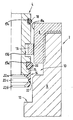
- the single drawing figure shows a schematic embodiment of the connector according to the invention in half section, in a schematic, not to scale, with respect to the size ratios - in particular as regards an annular gap between the plug-in parts, this essentially consisting of a housing part 2 and a plug part 4.
- the housing part 2 is preferably made in two parts and consists of a receiving part 6 and a closure part 8. These two parts are releasably connected to each other by any connecting means, such as a snap connection, a bayonet connection, but - as shown - in particular by a screw connection, the receiving part 6 preferably has an internal thread and the closure part 8 preferably has an external thread.
- the receiving part 6 seen in the insertion direction has a two-stage stepped bore, the first stage forming a retaining groove 10 with the annular end face of the screwed-in closure part 8 and the second stage forming a kind of limiting stage 12 for the plug part 4 to be inserted.
- the plug part 4 preferably has three circumferential annular grooves 13a, 13b, 13c on the outer surface of its plug-in section to be inserted. These annular grooves serve in particular to hold a combination element 14, a holding element 16 and a dirt seal 18.
- the combination element 14 is in one piece, made of a preferably ring-shaped sealing element 20 as the main seal, a preferably also ring-shaped spring element 22 and a connecting part 24 connecting these two parts, existing (rubber) elastic part (molded part).
- the combination element 14 can consist of the same material as natural or synthetic rubber (rubber) or a suitable plastic.
- any combination of materials is possible;
- a first material that is advantageous in terms of the density and in the area of the spring element 22 a second material that is favorable in terms of spring elasticity, and possibly a third material for the connecting part 24, can be used, the materials should be able to be connected homogeneously.
- both the combination element 14 and the holding element 16 and the dirt seal 18 are held on the plug part 4 by sitting in one of the three ring grooves of the plug part 4.
- the combination element 14 is seen in the pull-out direction with the sealing element 20 in the first annular groove 13a of the plug part 4 so close to the free end region of the plug part 4 that the spring element 22 of the combination element 14 is arranged on the end face of the plug part 4, the connecting part 24 extends from the sealing element 20 in the axial direction along the outer surface of the plug part 4 to the spring element 22.
- the spring element 22 When the plug part 4 is inserted, the spring element 22 can thus be elastically compressed between the end face of the plug part 4 and the limiting step 12 of the housing part 2 such that an axial pretension is generated between these two parts.
- the spring element 22 preferably consists from two ring-shaped, web-like, radially inward-pointing, elastic parts 22a, 22b, which are axially spaced apart and connected to one another on the housing wall side via a connecting part 22c, which is preferably designed as a circumferentially closed elastic ring element.
- the holding element 16 is preferably arranged in the second annular groove 13b of the plug part 4, which is axially spaced from the first annular groove 13a when viewed in the direction of extraction.
- the holding element 16 is preferably designed as a radially elastic, slotted holding ring which, when plugged in, widens into the holding groove 10 of the housing part 2 in such a way that the plug part 4 is held in the housing part 2 in a non-positive and / or positive manner.
- the plug part 4 is sealed in the inserted state by the dirt seal 18 arranged in the third annular groove 13c of the plug part 4 against the inner wall of the housing part 2 or against the inner surface 8a of the hollow cylindrical closure part 8.
- the sealing element 20 and the spring element 22 are connected to one another via the connecting part 24 designed as a circumferentially closed connecting ring.
- this connecting part 24 in the form of a single or a plurality of connecting webs.
- the arrangement of combination element 14, holding element 16 and dirt seal 18 is on the Plug part 4 is not mandatory, but it is also possible to arrange the combination element 14 within the housing part, in particular in the area of the limiting step 12, the holding element 16 then being able to be arranged either on the plug part 4 or in the housing part 2.
- the combination element 14 - as described - should be arranged on the plug part 4, it proves to be entirely advantageous to also arrange the holding element 16 on the plug part 4; otherwise, if the combination element 14 were arranged on the plug part 4 and the holding element 16 within the housing part 2, the combination element 14 would have to be guided past the holding element 16 during each plugging process and could possibly be damaged during this process. Furthermore, it is conceivable for the non-positive and / or positive interaction with the holding element 16, the corresponding connector or housing part 4.2 (depending on the arrangement of the holding element 16) - instead of a groove - for this purpose with a simple radial step surface To be provided.
- the combination element 14 can also consist of originally several individual parts, which are connected to one another in particular by a material connection.
- a different type of spring can also be provided as the spring element (e.g. compression spring made of spring steel bonded to the sealing element, in particular by vulcanizing or gluing).
Abstract
Description
Die vorliegende Erfindung betrifft eine Steckverbindung für Druckmittelleitungen, bestehend aus einem Gehäuseteil und einem Steckerteil, wobei das Gehäuseteil einen Aufnahmebereich für das einzusteckende Steckerteil aufweist und im eingesteckten Zustand zwischen der Innenfläche des Gehäuseteils und der Außenfläche des Steckerteils mindestens ein Halteelement zum kraft- und/oder formschlüssigen Arretieren von Gehäuseteil und Steckerteil sowie ein Dichtungselement zur Abdichtung zwischen diesen beiden Teilen und ein Federelement zur Erzeugung einer axialen Vorspannung innerhalb der Steckverbindung angeordnet sind.The present invention relates to a plug connection for pressure medium lines, consisting of a housing part and a plug part, the housing part having a receiving area for the plug part to be inserted and in the inserted state between the inner surface of the housing part and the outer surface of the plug part, at least one holding element for force and / or positive locking of the housing part and plug part as well as a sealing element for sealing between these two parts and a spring element for generating an axial preload are arranged within the plug connection.
Eine derartige Steckverbindung ist beispielsweise aus der EP 0 005 865 B1 bereits bekannt. Diese Steckverbindung besteht im wesentlichen aus einem zweiteiligen, verschraubbaren Gehäuseteil und einem mit dem Gehäuseteil lösbar verbindbaren Kupplungsteil, wobei in dem Gehäuseteil ein axial wirkendes Federelement und auf dem Kupplungsteil in Herausziehrichtung gesehen axial voneinander beabstandet ein Haltering und ein für die Druckabdichtung maßgeblicher Dichtungsring (Hauptdichtung) angeordnet sind. In einer anderen Ausführungsform dieser Steckverbindung ist der Dichtungsring in Einsteckrichtung gesehen von dem Haltering beabstandet und das Federelement nicht innerhalb, sondern im eingesteckten Zustand gesehen außerhalb des Gehäuseteils zwischen Kupplungs- und Gehäuseteil auf dem Kupplungsteil angeordnet.Such a plug connection is already known, for example, from EP 0 005 865 B1. This plug-in connection essentially consists of a two-part, screwable housing part and a coupling part which can be detachably connected to the housing part, an axially acting spring element in the housing part and a retaining ring and a sealing ring (main seal), which is decisive for the pressure seal, viewed axially apart on the coupling part. are arranged. In another Embodiment of this plug-in connection, the sealing ring is spaced from the retaining ring, as seen in the insertion direction, and the spring element is not arranged on the coupling part, but seen inside, but in the inserted state, outside the housing part between the coupling part and the housing part.
Derartige Steckverbindungen haben sich bisher bereits gut bewährt und sollen weiter verbessert werden.Plug-in connections of this type have already proven themselves well and are to be improved further.
Der vorliegenden Erfindung liegt die Aufgabe zugrunde, eine Steckverbindung zu schaffen, die die Vorteile einer schnell lösbaren und sicheren Steckverbindung in sich vereint und die Abdichtung zwischen Stecker und Gehäuseteil sowie eine axiale Vorspannung zwischen diesen beiden Teilen mit einfachsten Mitteln gewährleistet und eine Montage von Dicht- und Federelement deutlich erleichtert.The present invention has for its object to provide a connector that combines the advantages of a quick-release and secure connector and ensures the seal between the connector and the housing part and an axial preload between these two parts with the simplest means and an assembly of sealing and spring element significantly facilitated.
Erfindungsgemäß wird dies dadurch erreicht, daß das Federelement und das Dichtungselement als einteiliges Kombinationselement - bevorzugt einheitlich aus einem elastischen Material bestehend - ausgeführt sind. In der bevorzugten Ausführungsform der Steckverbindung ist das Kombinationselement derart auf dem Steckerteil angeordnet, daß es mit seinem Dichtungselement in einer Ringnut des Steckerteils gehalten ist, so daß das Federelement vorzugsweise auf der Stirnfläche des Steckerteils angeordnet ist und diese beiden Teile über ein Verbindungsteil, vorzugsweise einen umfänglich geschlossenen Verbindungsring, miteinander verbunden sind. In einer weiteren Ausführungsform der Erfindung ist es vorgesehen, dieses Kombinationselement innerhalb des Gehäuseteils anzuordnen, so daß das Kombinationselement mit seinem ringförmigen Dichtungselement innerhalb einer Ringnut des Gehäuseteils und das Federelement in Einsteckrichtung gesehen im Endbereich der Aufnahme des Gehäuseteils auf einer Begrenzungsstufe angeordnet ist.According to the invention, this is achieved in that the spring element and the sealing element are designed as a one-piece combination element - preferably consisting uniformly of an elastic material. In the preferred embodiment of the plug connection, the combination element is arranged on the plug part such that it is held with its sealing element in an annular groove of the plug part, so that the spring element is preferably arranged on the end face of the plug part and these two parts are connected via a connecting part, preferably one circumferentially closed connecting ring, are interconnected. In a further embodiment of the invention, it is provided to arrange this combination element within the housing part, so that the combination element with its annular sealing element within an annular groove of the housing part and the spring element in Seen insertion direction is arranged in the end region of the receptacle of the housing part on a limit step.
Weitere vorteilhafte Ausgestaltungsmerkmale der Erfindung sind in den nachfolgenden Figuren der Zeichnung sowie in den Unteransprüchen enthalten.Further advantageous design features of the invention are contained in the following figures of the drawing and in the subclaims.
Die einzige Zeichnungsfigur zeigt in einer schematischen, bezüglich der Größenverhältnisse - insbesondere was einen Ringspalt zwischen den Steckteilen betrifft - nicht maßstäblichen Prinzip-Darstellung eine bevorzugte Ausführungsform der erfindungsgemäßen Steckverbindung im Halbschnitt, wobei diese im wesentlichen aus einem Gehäuseteil 2 und einem Steckerteil 4 besteht. Dabei ist das Gehäuseteil 2 vorzugsweise zweiteilig ausgeführt und besteht aus einem Aufnahmeteil 6 und einem Verschlußteil 8. Diese beiden Teile sind über beliebige Verbindungsmittel, wie eine Rastverbindung, eine Bajonettverbindung, aber - wie dargestellt - insbesondere über eine Schraubverbindung lösbar miteinander verbunden, wobei das Aufnahmeteil 6 vorzugsweise ein Innengewinde und das Verschlußteil 8 vorzugsweise ein Außengewinde aufweist. Mit Vorteil weist das Aufnahmeteil 6 in Einsteckrichtung gesehen eine zweistufige Stufenbohrung auf, wobei die erste Stufe mit der ringförmigen Stirnfläche des eingeschraubten Verschlußteils 8 eine Haltenut 10 und die zweite Stufe eine Art Begrenzungsstufe 12 für das einzusteckende Steckerteil 4 bildet.The single drawing figure shows a schematic embodiment of the connector according to the invention in half section, in a schematic, not to scale, with respect to the size ratios - in particular as regards an annular gap between the plug-in parts, this essentially consisting of a
Das Steckerteil 4 weist auf der Außenfläche seines einzusteckenden Steckabschnittes vorzugsweise drei umfängliche Ringnuten 13a,13b,13c auf. Diese Ringnuten dienen insbesondere der Halterung eines Kombinationselementes 14, eines Halteelementes 16 sowie einer Schmutzdichtung 18. Das Kombinationselement 14 ist erfindungsgemäß als einteiliges, aus einem vorzugsweise ringförmigen Dichtungselement 20 als Hauptdichtung, einem vorzugsweise ebenfalls ringförmigen Federelement 22 und einem diese beiden Teile verbindenden Verbindungsteil 24 bestehendes (gummi-)elastisches Teil (Formteil) ausgeführt. Das Kombinationselement 14 kann dabei materialeinheitlich aus Natur- oder Kunstkautschuk (Gummi) oder einem geeigneten Kunststoff bestehen. Es sind auch beliebige Material-Kombinationen möglich; vorteilhafterweise kann im Bereich des Dichtungselementes 20 ein erstes, dichtspezifisch vorteilhaftes Material und im Bereich des Federelementes 22 ein zweites, bezüglich der Federelastizität günstiges Material sowie eventuell für den Verbindungsteil 24 ein drittes Material eingesetzt werden, wobei die Materialien homogen verbindbar sein sollten.The plug part 4 preferably has three circumferential
In einer bevorzugten Ausführungsform der Steckverbindung sind sowohl das Kombinationselement 14 als auch das Halteelement 16 und die Schmutzdichtung 18 am Steckerteil 4 gehalten, indem sie in jeweils einer der drei Ringnuten des Steckerteils 4 sitzen. Erfindungsgemäß ist dabei das Kombinationselement 14 in Herausziehrichtung gesehen mit dem Dichtungselement 20 in der ersten Ringnut 13a des Steckerteils 4 derart nahe dem freien Stirnbereich des Steckerteils 4 angeordnet, daß das Federelement 22 des Kombinationselementes 14 auf der Stirnfläche des Steckerteils 4 angeordnet ist, wobei der Verbindungsteil 24 sich vom Dichtungselement 20 in axialer Richtung entlang der Außenfläche des Steckerteils 4 bis zum Federelement 22 erstreckt. Im eingesteckten Zustand des Steckerteils 4 kann somit das Federelement 22 zwischen der Stirnfläche des Steckerteils 4 und der Begrenzungsstufe 12 des Gehäuseteils 2 derart elastisch zusammengedrückt werden, daß zwischen diesen beiden Teilen eine axiale Vorspannung erzeugt wird. Das Federelement 22 besteht wie dargestellt vorzugsweise aus zwei ringförmigen, stegartig radial nach innen weisenden, elastischen Teilen 22a, 22b, die axial voneinander beabstandet und gehäusewandseitig über ein vorzugsweise als umfänglich geschlossenes elastisches Ringelement ausgeführtes Verbindungsteil 22c miteinander verbunden sind. Dadurch wird bei einem axialen Zusammendrücken des Federelements 22 insbesondere das Verbindungsteil 22c in Richtung Gehäusewand radial nach außen gedrückt und so eine zusätzliche gute Abdichtung zwischen dem Steckerteil 4 und dem Gehäuseteil 2 erreicht.In a preferred embodiment of the plug connection, both the
Vorzugsweise ist in der zweiten Ringnut 13b des Steckerteils 4, die in Herausziehrichtung gesehen axial von der ersten Ringnut 13a beabstandet ist, das Halteelement 16 angeordnet. Das Halteelement 16 ist vorzugsweise als radial elastischer, geschlitzter Haltering ausgeführt, der sich im eingesteckten Zustand in die Haltenut 10 des Gehäuseteils 2 derart erweitert, daß das Steckerteil 4 kraft- und/oder formschlüssig im Gehäuseteil 2 gehalten ist. Dabei ist das Steckerteil 4 im eingesteckten Zustand durch die in der dritten Ringnut 13c des Steckerteils 4 angeordnete Schmutzdichtung 18 gegen die Innenwand des Gehäuseteils 2 bzw. gegen die Innenfläche 8a des hohlzylindrischen Verschlußteils 8 abgedichtet.The
In einer bevorzugten Ausführungsform des erfindungsgemäßen Kombinationselementes 14 sind das Dichtungselement 20 und das Federelement 22 über das als umfänglich geschlossener Verbindungsring ausgeführte Verbindungsteil 24 miteinander verbunden. Alternativ dazu ist es natürlich ebenfalls denkbar, dieses Verbindungsteil 24 in Form eines einzelnen oder mehrerer Verbindungsstege auszuführen. Bei der erfindungsgemäßen Steckverbindung ist die Anordnung von Kombinationselement 14, Halteelement 16 und Schmutzdichtung 18 auf dem Steckerteil 4 nicht zwingend, sondern es ist ebenfalls möglich, das Kombinationselement 14 innerhalb des Gehäuseteils, insbesondere im Bereich der Begrenzungsstufe 12 anzuordnen, wobei das Halteelement 16 dann entweder auf dem Steckerteil 4 oder aber im Gehäuseteil 2 angeordnet sein kann. Falls das Kombinationselement 14 jedoch - wie beschrieben - am Steckerteil 4 angeordnet sein sollte, erweist es sich als durchaus vorteilhaft, das Halteelement 16 ebenfalls am Steckerteil 4 anzuordnen; denn wenn anderenfalls das Kombinationselement 14 am Steckerteil 4 und das Halteelement 16 innerhalb des Gehäuseteils 2 angeordnet wären, würde das Kombinationselement 14 bei jedem Steckvorgang an dem Halteelement 16 vorbeigeführt werden müssen und könnte bei diesem Vorgang evtl. beschädigt werden. Weiterhin ist es denkbar, für das kraft- und/oder formschlüssige Zusammenwirken mit dem Haltelement 16 das entsprechende Stecker- bzw. Gehäuseteil 4,2 (je nach Anordnung des Halteelementes 16) - anstatt mit einer Nut - zu diesem Zweck mit einer einfachen radialen Stufenfläche (Raststufe) zu versehen.In a preferred embodiment of the
Die Erfindung ist nicht auf das dargestellte und beschriebene Ausführungsbeispiel beschränkt, sondern umfaßt auch alle im Sinne der Erfindung gleichwirkenden Ausführungsformen. So kann das Kombinationselement 14 auch aus ursprünglich mehreren Einzelteilen bestehen, die insbesondere stoffschlüssig miteinander verbunden werden. Dabei kann als Federelement anstatt eines gummielastischen Puffers auch eine andere Federart vorgesehen sein (z.B. Druckfeder aus Federstahl stoffschlüsssig, insbesondere durch Vulkanisieren oder Verkleben, mit dem Dichtungselement verbunden).The invention is not limited to the exemplary embodiment shown and described, but also encompasses all the embodiments having the same effect in the sense of the invention. Thus, the
Claims (11)
dadurch gekennzeichnet, daß das Federelement (22) und das Dichtungselement (20) als einteiliges Kombinationselement (14) ausgeführt sind.Plug connection for pressure medium lines, consisting of a housing part (2) and a plug part (4), the housing part (2) having a receiving area for the plug part (4) to be inserted and in the inserted state between the inner surface of the housing part (2) and the outer surface of the Plug part (4) at least one holding element (16) for non-positively and / or positively locking the housing part (2) and plug part (4) as well as a sealing element (20) for sealing between these two parts and a spring element (22) for generating an axial Bias is arranged within the connector,
characterized in that the spring element (22) and the sealing element (20) are designed as a one-piece combination element (14).
dadurch gekennzeichnet, daß das Gehäuseteil (2) eine in Einsteckrichtung gesehen den Aufnahmebereich begrenzende und den Innenquerschnitt des Gehäuseteils (2) verkleinernde Begrenzungsstufe (12) aufweist, die im eingesteckten und arretierten Zustand des Steckerteils (4) derart mit dem Federelement (22) des Kombinationselementes (14) zusammenwirkt, daß in Herausziehrichtung gesehen die axiale Vorspannung zwischen dem Steckerteil (4) und dem Gehäuseteil (2) erreicht wird.Connector according to claim 1,
characterized in that the housing part (2), viewed in the direction of insertion, delimits the receiving area and the inner cross section of the housing part (2) has a limiting step (12) which, when the plug part (4) is inserted and locked, interacts with the spring element (22) of the combination element (14) such that the axial preload between the plug part (4) when viewed in the direction of extraction and the housing part (2) is reached.
dadurch gekennzeichnet, daß das Kombinationselement (14) im einzusteckenden Stirnbereich des Steckerteils (4) auf diesem angeordnet ist, wobei das Dichtungselement (20) als Ringdichtung ausgeführt und in einer ersten Ringnut (13a) des Steckerteils (4) gehalten ist und das Federelement (22) als elastisches Ringteil auf der Stirnfläche des Steckerteils (4) angeordnet ist und diese beiden Teile über einen Verbindungsteil (24) einteilig verbunden sind.Plug connection according to claim 1 or 2,
characterized in that the combination element (14) is arranged in the end region of the plug part (4) to be inserted, the sealing element (20) being designed as an annular seal and being held in a first annular groove (13a) of the plug part (4) and the spring element ( 22) is arranged as an elastic ring part on the end face of the plug part (4) and these two parts are connected in one piece via a connecting part (24).
dadurch gekennzeichnet, daß das Kombinationselement (14) auf der Innenfläche des Gehäuseteils (2) angeordnet ist, wobei das Dichtungselement (20) in einer ersten Ringnut des Gehäuseteils (2) gehalten ist und das Federelement (22) vorzugsweise auf einer Begrenzungstufe (12) im Innern des Gehäuseteils (2) aufliegt und diese beiden Teile über einen Verbindungsteil (24) einteilig verbunden sind.Plug connection according to claim 1 or 2,
characterized in that the combination element (14) is arranged on the inner surface of the housing part (2), the sealing element (20) being held in a first annular groove of the housing part (2) and the spring element (22) preferably on a limiting step (12) rests in the interior of the housing part (2) and these two parts are connected in one piece via a connecting part (24).
dadurch gekennzeichnet, daß der Verbindungsteil (24) als umfänglich geschlossener Verbindungsring ausgeführt ist.Connector according to claim 3 or 4,
characterized in that the connecting part (24) is designed as a circumferentially closed connecting ring.
dadurch gekennzeichnet, daß der Verbindungsteil (24) zwischen Dichtungselement (20) und Federelement (22) aus mindestens einem Verbindungssteg, vorzugsweise aus mehreren über den Umfang verteilt angeordneten Verbindungsstegen, besteht.Connector according to claim 3 or 4,
characterized in that the connecting part (24) between the sealing element (20) and the spring element (22) consists of at least one connecting web, preferably of a plurality of connecting webs distributed over the circumference.
dadurch gekennzeichnet, daß das Halteelement (16) in Herausziehrichtung gesehen von dem Kombinationselement (14) beabstandet in einer zweiten Ringnut (13b) auf dem Steckerteil (4) angeordnet ist und das Gehäuseteil (2) eine radiale Stufenfläche zum kraft- und/oder formschlüssigen Zusammenwirken mit dem auf dem Steckerteil (4) angeordneten Halteelement (16) aufweist.Plug connection according to one or more of claims 1 to 6,
characterized in that the holding element (16), viewed in the pull-out direction, is spaced apart from the combination element (14) in a second annular groove (13b) on the plug part (4) and the housing part (2) has a radial step surface for positive and / or positive locking Cooperation with the holding element (16) arranged on the plug part (4).
dadurch gekennzeichnet, daß das Halteelement (16) auf der Innenfläche des Gehauseteils (2) in Herausziehrichtung gesehen axial von dem Kombinationselement (14) beabstandet in einer zweiten Ring-nut des Gehäuseteils (2) angeordnet ist und das Steckerteil (4) eine radiale Stufenfläche zum kraft- und/oder formschlüssigen Zusammenwirken mit dem im Gehäuseteil (2) angeordneten Halteelement (16) aufweist.Plug connection according to one or more of claims 1 to 6,
characterized in that the holding element (16) on the inner surface of the housing part (2), viewed in the pull-out direction, is arranged axially at a distance from the combination element (14) in a second annular groove of the housing part (2) and the plug part (4) has a radial step surface for non-positive and / or positive interaction with the holding element (16) arranged in the housing part (2).
dadurch gekennzeichnet, daß das Halteelement (16) als geschlitzter radialelastischer Haltering ausgeführt ist.Plug connection according to one or more of claims 1 to 8,
characterized in that the Holding element (16) is designed as a slotted radially elastic retaining ring.
dadurch gekennzeichnet, daß in einer weiteren Ringnut (13c) des Steckerteils (4) in Herausziehrichtung gesehen vom Halteelement (16) beabstandet eine Schmutzdichtung (18) angeordnet ist.Plug connection according to one or more of claims 1 to 9,
characterized in that a dirt seal (18) is arranged at a distance from the holding element (16) in a further annular groove (13c) of the plug part (4) as seen in the pull-out direction.
dadurch gekennzeichnet, daß das Gehäuseteil (2) zweiteilig ausgeführt ist und aus einem Aufnahmeteil (6) und einem Verschlußteil (8) besteht, wobei diese beiden Teile lösbar miteinander verbunden sind.Plug connection according to one or more of claims 1 to 10,
characterized in that the housing part (2) is made in two parts and consists of a receiving part (6) and a closure part (8), these two parts being releasably connected to one another.
Applications Claiming Priority (2)
| Application Number | Priority Date | Filing Date | Title |
|---|---|---|---|
| DE19523298 | 1995-06-27 | ||
| DE19523298A DE19523298A1 (en) | 1995-06-27 | 1995-06-27 | Plug connection for pressure medium lines |
Publications (2)
| Publication Number | Publication Date |
|---|---|
| EP0751333A1 true EP0751333A1 (en) | 1997-01-02 |
| EP0751333B1 EP0751333B1 (en) | 2000-08-02 |
Family
ID=7765351
Family Applications (1)
| Application Number | Title | Priority Date | Filing Date |
|---|---|---|---|
| EP96107140A Expired - Lifetime EP0751333B1 (en) | 1995-06-27 | 1996-05-07 | Plug connector for pressure conduit systems |
Country Status (2)
| Country | Link |
|---|---|
| EP (1) | EP0751333B1 (en) |
| DE (2) | DE19523298A1 (en) |
Cited By (1)
| Publication number | Priority date | Publication date | Assignee | Title |
|---|---|---|---|---|
| WO2015135663A3 (en) * | 2014-03-14 | 2016-01-14 | Voss Automotive Gmbh | Line connection device for releasably connecting media conduits, or at least one media conduit and at least one assembly |
Citations (4)
| Publication number | Priority date | Publication date | Assignee | Title |
|---|---|---|---|---|
| EP0005865A2 (en) * | 1978-06-07 | 1979-12-12 | Armaturenfabrik Hermann Voss GmbH + Co. | Plug-type connecting system for pressurised conduits, in particular for brake system conduits |
| DE3235058A1 (en) * | 1982-09-22 | 1984-03-22 | Armaturenfabrik Hermann Voss GmbH + Co, 5272 Wipperfürth | Plug-in coupling for pressure lines, in particular plastic lines for brake systems for motor vehicles |
| DE3341029A1 (en) * | 1982-06-16 | 1985-05-23 | Armaturenfabrik Hermann Voss GmbH + Co, 5272 Wipperfürth | Plug connection for systems to which a pressure medium can be applied |
| US5112086A (en) * | 1990-06-25 | 1992-05-12 | Flexa Gmbh & Co. Produktion Und Vertrieb Kg | Coupling device for a corrugated pipe or hose |
-
1995
- 1995-06-27 DE DE19523298A patent/DE19523298A1/en not_active Withdrawn
-
1996
- 1996-05-07 DE DE59605671T patent/DE59605671D1/en not_active Expired - Lifetime
- 1996-05-07 EP EP96107140A patent/EP0751333B1/en not_active Expired - Lifetime
Patent Citations (4)
| Publication number | Priority date | Publication date | Assignee | Title |
|---|---|---|---|---|
| EP0005865A2 (en) * | 1978-06-07 | 1979-12-12 | Armaturenfabrik Hermann Voss GmbH + Co. | Plug-type connecting system for pressurised conduits, in particular for brake system conduits |
| DE3341029A1 (en) * | 1982-06-16 | 1985-05-23 | Armaturenfabrik Hermann Voss GmbH + Co, 5272 Wipperfürth | Plug connection for systems to which a pressure medium can be applied |
| DE3235058A1 (en) * | 1982-09-22 | 1984-03-22 | Armaturenfabrik Hermann Voss GmbH + Co, 5272 Wipperfürth | Plug-in coupling for pressure lines, in particular plastic lines for brake systems for motor vehicles |
| US5112086A (en) * | 1990-06-25 | 1992-05-12 | Flexa Gmbh & Co. Produktion Und Vertrieb Kg | Coupling device for a corrugated pipe or hose |
Cited By (3)
| Publication number | Priority date | Publication date | Assignee | Title |
|---|---|---|---|---|
| WO2015135663A3 (en) * | 2014-03-14 | 2016-01-14 | Voss Automotive Gmbh | Line connection device for releasably connecting media conduits, or at least one media conduit and at least one assembly |
| CN106415105A (en) * | 2014-03-14 | 2017-02-15 | 福士汽车配套部件责任有限公司 | Line connection device for releasably connecting media conduits, or at least one media conduit and at least one assembly |
| CN106415105B (en) * | 2014-03-14 | 2019-06-14 | 福士汽车配套部件责任有限公司 | For being releasably attached the connecting device for line of media lines or at least one media lines and at least one component |
Also Published As
| Publication number | Publication date |
|---|---|
| DE19523298A1 (en) | 1997-01-02 |
| DE59605671D1 (en) | 2000-09-07 |
| EP0751333B1 (en) | 2000-08-02 |
Similar Documents
| Publication | Publication Date | Title |
|---|---|---|
| EP0005865B1 (en) | Plug-type connecting system for pressurised conduits, in particular for brake system conduits | |
| DE3121899C2 (en) | ||
| EP1920183B1 (en) | Connector device for media conduits | |
| EP0665402A1 (en) | Plug connector for pressure pipe systems | |
| EP1106896B1 (en) | Plug coupling for pressure fluid systems | |
| DE4232964C2 (en) | Pipe coupling | |
| DE202013002839U1 (en) | clutch unit | |
| WO1984001902A1 (en) | Catheter coupling | |
| EP0549860A1 (en) | Coupling device for two conducts, in particular for fuel conducts | |
| DE3019417A1 (en) | HOSE COUPLING, IN PARTICULAR FOR MEDICAL PURPOSES | |
| EP0718538B1 (en) | Plug coupling | |
| DE2627397A1 (en) | CONNECTOR | |
| DE4243844B4 (en) | Connection device for pipes | |
| DE3010459C2 (en) | ||
| EP0751333A1 (en) | Plug connector for pressure conduit systems | |
| DE102016117830A1 (en) | Connector assembly for media lines and method for connecting media lines | |
| EP1396671A1 (en) | Receiving part of a fluid plug-in coupling | |
| DE4019408A1 (en) | Plug coupling attaching hose to mounting - consists of housing with hole for plug, with sleeve and expander pieces | |
| EP0647803B1 (en) | Plug coupling for pressure fluid system | |
| DE3235058A1 (en) | Plug-in coupling for pressure lines, in particular plastic lines for brake systems for motor vehicles | |
| DE3341029A1 (en) | Plug connection for systems to which a pressure medium can be applied | |
| DE202008009398U1 (en) | Plug-in coupling for pressure medium lines | |
| EP1006307A1 (en) | Pin-and-socket coupling | |
| EP0733845A1 (en) | Connecting device for the connection of pipes to a unit | |
| DE3419633A1 (en) | Tension and shear protection device for screw-collar connections of pipes |
Legal Events
| Date | Code | Title | Description |
|---|---|---|---|
| PUAI | Public reference made under article 153(3) epc to a published international application that has entered the european phase |
Free format text: ORIGINAL CODE: 0009012 |
|
| AK | Designated contracting states |
Kind code of ref document: A1 Designated state(s): DE FR GB IT NL SE |
|
| 17P | Request for examination filed |
Effective date: 19970215 |
|
| 17Q | First examination report despatched |
Effective date: 19970430 |
|
| GRAG | Despatch of communication of intention to grant |
Free format text: ORIGINAL CODE: EPIDOS AGRA |
|
| GRAG | Despatch of communication of intention to grant |
Free format text: ORIGINAL CODE: EPIDOS AGRA |
|
| GRAH | Despatch of communication of intention to grant a patent |
Free format text: ORIGINAL CODE: EPIDOS IGRA |
|
| GRAH | Despatch of communication of intention to grant a patent |
Free format text: ORIGINAL CODE: EPIDOS IGRA |
|
| GRAA | (expected) grant |
Free format text: ORIGINAL CODE: 0009210 |
|
| AK | Designated contracting states |
Kind code of ref document: B1 Designated state(s): DE FR GB IT NL SE |
|
| GBT | Gb: translation of ep patent filed (gb section 77(6)(a)/1977) |
Effective date: 20000802 |
|
| REF | Corresponds to: |
Ref document number: 59605671 Country of ref document: DE Date of ref document: 20000907 |
|
| ET | Fr: translation filed | ||
| ITF | It: translation for a ep patent filed |
Owner name: ING. A. GIAMBROCONO & C. S.R.L. |
|
| PLBE | No opposition filed within time limit |
Free format text: ORIGINAL CODE: 0009261 |
|
| STAA | Information on the status of an ep patent application or granted ep patent |
Free format text: STATUS: NO OPPOSITION FILED WITHIN TIME LIMIT |
|
| 26N | No opposition filed | ||
| REG | Reference to a national code |
Ref country code: GB Ref legal event code: IF02 |
|
| REG | Reference to a national code |
Ref country code: FR Ref legal event code: CD |
|
| PGFP | Annual fee paid to national office [announced via postgrant information from national office to epo] |
Ref country code: IT Payment date: 20080326 Year of fee payment: 13 |
|
| PGFP | Annual fee paid to national office [announced via postgrant information from national office to epo] |
Ref country code: SE Payment date: 20080509 Year of fee payment: 13 Ref country code: NL Payment date: 20080501 Year of fee payment: 13 |
|
| PGFP | Annual fee paid to national office [announced via postgrant information from national office to epo] |
Ref country code: GB Payment date: 20090506 Year of fee payment: 14 |
|
| NLV4 | Nl: lapsed or anulled due to non-payment of the annual fee |
Effective date: 20091201 |
|
| PG25 | Lapsed in a contracting state [announced via postgrant information from national office to epo] |
Ref country code: NL Free format text: LAPSE BECAUSE OF NON-PAYMENT OF DUE FEES Effective date: 20091201 |
|
| REG | Reference to a national code |
Ref country code: FR Ref legal event code: ST Effective date: 20100129 |
|
| PG25 | Lapsed in a contracting state [announced via postgrant information from national office to epo] |
Ref country code: FR Free format text: LAPSE BECAUSE OF NON-PAYMENT OF DUE FEES Effective date: 20090602 |
|
| PGFP | Annual fee paid to national office [announced via postgrant information from national office to epo] |
Ref country code: FR Payment date: 20080514 Year of fee payment: 13 |
|
| PGFP | Annual fee paid to national office [announced via postgrant information from national office to epo] |
Ref country code: DE Payment date: 20100730 Year of fee payment: 15 |
|
| GBPC | Gb: european patent ceased through non-payment of renewal fee |
Effective date: 20100507 |
|
| PG25 | Lapsed in a contracting state [announced via postgrant information from national office to epo] |
Ref country code: IT Free format text: LAPSE BECAUSE OF NON-PAYMENT OF DUE FEES Effective date: 20090507 |
|
| PG25 | Lapsed in a contracting state [announced via postgrant information from national office to epo] |
Ref country code: SE Free format text: LAPSE BECAUSE OF NON-PAYMENT OF DUE FEES Effective date: 20090508 |
|
| PG25 | Lapsed in a contracting state [announced via postgrant information from national office to epo] |
Ref country code: GB Free format text: LAPSE BECAUSE OF NON-PAYMENT OF DUE FEES Effective date: 20100507 |
|
| REG | Reference to a national code |
Ref country code: DE Ref legal event code: R119 Ref document number: 59605671 Country of ref document: DE |
|
| REG | Reference to a national code |
Ref country code: DE Ref legal event code: R119 Ref document number: 59605671 Country of ref document: DE |
|
| PG25 | Lapsed in a contracting state [announced via postgrant information from national office to epo] |
Ref country code: DE Free format text: LAPSE BECAUSE OF NON-PAYMENT OF DUE FEES Effective date: 20111130 |