EP0751045A2 - Power supply system for a vehicle with an internal combustion engine - Google Patents
Power supply system for a vehicle with an internal combustion engine Download PDFInfo
- Publication number
- EP0751045A2 EP0751045A2 EP96107325A EP96107325A EP0751045A2 EP 0751045 A2 EP0751045 A2 EP 0751045A2 EP 96107325 A EP96107325 A EP 96107325A EP 96107325 A EP96107325 A EP 96107325A EP 0751045 A2 EP0751045 A2 EP 0751045A2
- Authority
- EP
- European Patent Office
- Prior art keywords
- fuel
- combustion engine
- internal combustion
- fuel cell
- hydrogen
- Prior art date
- Legal status (The legal status is an assumption and is not a legal conclusion. Google has not performed a legal analysis and makes no representation as to the accuracy of the status listed.)
- Granted
Links
Images
Classifications
-
- H—ELECTRICITY
- H02—GENERATION; CONVERSION OR DISTRIBUTION OF ELECTRIC POWER
- H02J—CIRCUIT ARRANGEMENTS OR SYSTEMS FOR SUPPLYING OR DISTRIBUTING ELECTRIC POWER; SYSTEMS FOR STORING ELECTRIC ENERGY
- H02J1/00—Circuit arrangements for dc mains or dc distribution networks
-
- B—PERFORMING OPERATIONS; TRANSPORTING
- B60—VEHICLES IN GENERAL
- B60R—VEHICLES, VEHICLE FITTINGS, OR VEHICLE PARTS, NOT OTHERWISE PROVIDED FOR
- B60R16/00—Electric or fluid circuits specially adapted for vehicles and not otherwise provided for; Arrangement of elements of electric or fluid circuits specially adapted for vehicles and not otherwise provided for
- B60R16/02—Electric or fluid circuits specially adapted for vehicles and not otherwise provided for; Arrangement of elements of electric or fluid circuits specially adapted for vehicles and not otherwise provided for electric constitutive elements
- B60R16/03—Electric or fluid circuits specially adapted for vehicles and not otherwise provided for; Arrangement of elements of electric or fluid circuits specially adapted for vehicles and not otherwise provided for electric constitutive elements for supply of electrical power to vehicle subsystems or for
-
- H—ELECTRICITY
- H02—GENERATION; CONVERSION OR DISTRIBUTION OF ELECTRIC POWER
- H02J—CIRCUIT ARRANGEMENTS OR SYSTEMS FOR SUPPLYING OR DISTRIBUTING ELECTRIC POWER; SYSTEMS FOR STORING ELECTRIC ENERGY
- H02J2300/00—Systems for supplying or distributing electric power characterised by decentralized, dispersed, or local generation
- H02J2300/30—The power source being a fuel cell
-
- H—ELECTRICITY
- H02—GENERATION; CONVERSION OR DISTRIBUTION OF ELECTRIC POWER
- H02J—CIRCUIT ARRANGEMENTS OR SYSTEMS FOR SUPPLYING OR DISTRIBUTING ELECTRIC POWER; SYSTEMS FOR STORING ELECTRIC ENERGY
- H02J2310/00—The network for supplying or distributing electric power characterised by its spatial reach or by the load
- H02J2310/40—The network being an on-board power network, i.e. within a vehicle
- H02J2310/46—The network being an on-board power network, i.e. within a vehicle for ICE-powered road vehicles
Definitions
- the invention relates to a power generation system for a vehicle with an internal combustion engine according to claim 1, and a method for operating such a system.
- an alternator for generating electrical energy, which is driven by the internal combustion engine.
- the electricity supplied by the alternator is made available to the electrical consumers in the vehicle.
- the alternator is also used to charge the vehicle battery.
- the invention has for its object to provide a power generation system for a vehicle with an internal combustion engine, through which the current can be made available to the electrical consumers with reduced fuel consumption and regardless of the current speed of the internal combustion engine. It is also an object of the invention to provide a method for operating such a system.
- the use of a fuel cell system instead of an alternator in a vehicle with an internal combustion engine has the advantage that the electricity required can be provided with significantly reduced fuel consumption due to the better efficiency of the fuel cell.
- the power of the fuel cell can be set independently of the speed of the internal combustion engine, so that the current generated electrical power can be adapted to the respective need.
- auxiliary units such as fans or air conditioning compressors
- a fuel cell offers the possibility of providing electrical current even when the internal combustion engine is switched off, so that improvements, for example in the air conditioning of the vehicle, are made possible.
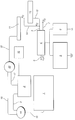
- the vehicle is driven with the aid of an internal combustion engine 1.
- a fuel tank 2 and a fuel line 3 are provided to supply the internal combustion engine 1 with liquid fuel.
- a fuel cell 4 is also arranged in the vehicle for generating electrical energy.
- An H 2 / O 2 fuel cell with a proton-conducting membrane, hereinafter referred to as a PEM cell, can preferably be used for this.
- PEM cell proton-conducting membrane
- the PEM cell 4 is supplied with oxygen via a first supply line 7 and hydrogen gas via a second supply line 8.
- the hydrogen is oxidized at the anode and the oxygen at the cathode is reduced.
- This electrochemical reaction creates a voltage between the two electrodes.
- many such cells can be combined into a so-called stack by connecting them in parallel or in series.
- pure hydrogen and oxygen only residual oxygen and water are released from the PEM cell 4 via an outlet line 9.
- the oxygen is supplied to the PEM cell 4 in the form of atmospheric oxygen.
- the required hydrogen is preferably separated from the fuel used for the internal combustion engine 1.
- Conventional fuels such as diesel, normal gasoline or methanol, contain hydrocarbons, from which hydrogen can be separated in a relatively simple manner, for example with the aid of a cracking plant 10.
- the exact structure of such splitting systems 10 is known in principle and is therefore not described further here.
- only a portion of the hydrogen is preferably separated from the fuel in the arrangement shown and the remaining fuel components subsequently recycled in internal combustion engine 1.
- the hydrogen is separated from the remaining fuel components in an H 2 separation system 11, the separated hydrogen being fed to the PEM cell 4 via a supply line 12.
- An H 2 intermediate store 13 can additionally be arranged in this supply line 12.
- This H 2 intermediate storage device 13 can be used, on the one hand, to supply the PEM cell 4 with hydrogen when the vehicle is started until the hydrogen supply via the gap system 10 is ready for operation.
- the hydrogen can then also be fed from the H 2 separation system 11 directly to the PEM cell 4 bypassing the H 2 intermediate storage 13 via a bypass line 14.
- Any device 11 known from the prior art can be used to separate the hydrogen from the remaining fuel components, for example based on metal foils.
- the fuel components remaining in the H 2 separation system 11 are discharged via a disposal line 15. There are several options for recycling these fuel components. Liquid components can be returned to the fuel tank 2 via a line 17. Gaseous constituents can be supplied to the internal combustion engine 1 via a line 18 either directly or preferably via a mixture generator 16, which is also connected to the fuel line 3. In this case, the mixture generator 16 is connected to the internal combustion engine 1 via a further line 19.
- An intermediate store 20 for the remaining fuel components can additionally be provided in the disposal line 15. This has the advantage that the remaining fuel components can be stored temporarily and can only be supplied to the internal combustion engine 1 when required. In the event that the PEM cell 4 is to be operated even when the internal combustion engine 1 is at a standstill, the use of such a buffer store 20 is particularly advantageous.
- the fuel components can then be fully or partially condensed in the intermediate store 20 and then fed to the fuel tank 2.
- the gaseous fuel components are then in turn fed to the internal combustion engine 1 via the mixture images 16.
- any other method can also be used to partially or completely separate hydrogen from the fuel, for example also by reforming the fuel.
- the current generated by the PEM cell 4 is supplied to the electrical consumers 5 in the vehicle.
- the electricity generated can be used to charge a battery 6, which is required to start the PEM cell 4 and / or the splitting system 10. An alternator is no longer used in this system.
- gaseous residues can be fed to the combustion engine 1 either directly or via the mixture pictures 16 for recycling.
- gaseous residues can also be buffered in the intermediate storage 20 and only supplied to the internal combustion engine 1 directly or again via the mixture images 16 with a time delay. It is also possible here to utilize the residues from the intermediate storage 20 only under predetermined operating conditions. If liquid constituents remain during the hydrogen separation, these can be fed to the fuel tank 2 as condensate. Care must be taken, however, that the fuel quality, in particular the ignitability, is not unduly impaired by the hydrogen separation.
- the PEM cell 4 can be operated as long as long as the internal combustion engine 1 is in operation and sufficient fuel is available. However, the operation of the PEM cell 4 is not restricted to the operating times of the internal combustion engine 1, as is the case with an alternator. Rather, it is also possible with this system to continue to generate electrical energy when the internal combustion engine 1 is at a standstill. Various concepts are possible for this. In the event of a brief interruption - in the range of a few minutes - hydrogen can be generated in the splitting system 10 until the intermediate store 20 is filled with the remaining fuel components. In the event of medium interruptions - in the range from 0.5 to 1.5 hours - the splitting system 10 can be switched off and the PEM cell 4 can be supplied with hydrogen from the H 2 intermediate store 13.
- the addition of suitable additives with low-boiling components into the fuel tank 2 can be provided to refresh the cleavability.
- the splitting system 10 can then be carried out relatively simply.
- the PEM cell 4 can be briefly supplied with hydrogen from the H 2 intermediate storage 13. Only after a predetermined operating time of the PEM cell 4 is the splitting system 10 started.
- the electrical energy for starting the PEM cell 4 and / or the gap system 10 is preferably provided by a battery 6. In such a system, the battery 6 can possibly be dimensioned correspondingly smaller in comparison to conventional vehicle batteries.
- the PEM cell 4 does not have to be operated with a constant load, but can be set as a function of the required current.
- a Control device which specifies the target power of the PEM cell 4 as a function of the number and the need of the connected electrical consumers 5.
Landscapes
- Engineering & Computer Science (AREA)
- Power Engineering (AREA)
- Fuel Cell (AREA)
- Output Control And Ontrol Of Special Type Engine (AREA)
- Electric Propulsion And Braking For Vehicles (AREA)
- Hybrid Electric Vehicles (AREA)
Abstract
Description
Die Erfindung betrifft ein Stromerzeugungssystem für ein Fahrzeug mit Brennkraftmaschine gemäß Patentanspruch 1, sowie ein Verfahren zum Betreiben eines solchen Systems.The invention relates to a power generation system for a vehicle with an internal combustion engine according to
Bei herkömmlichen Fahrzeugen ist zur Erzeugung von elektrischer Energie eine Lichtmaschine vorgesehen, die von der Brennkraftmaschine angetrieben wird. Der von der Lichtmaschine gelieferte Strom wird zum einen den elektrischen Verbrauchern im Fahrzeug zur Verfügung gestellt. Zum anderen dient die Lichtmaschine auch zum Laden der Fahrzeugbatterie.In conventional vehicles, an alternator is provided for generating electrical energy, which is driven by the internal combustion engine. The electricity supplied by the alternator is made available to the electrical consumers in the vehicle. On the other hand, the alternator is also used to charge the vehicle battery.
Der Erfindung liegt die Aufgabe zugrunde, ein Stromerzeugungssystem für ein Fahrzeug mit Brennkraftmaschine zu schaffen, durch welches der Strom für die elektrischen Verbraucher bei verringertem Kraftstoffverbrauch und unabhängig von der momentanen Drehzahl der Brennkraftmaschine zur Verfügung gestellt werden kann. Außerdem ist es Aufgabe der Erfindung, ein Verfahren zum Betreiben eines solchen Systems zu schaffen.The invention has for its object to provide a power generation system for a vehicle with an internal combustion engine, through which the current can be made available to the electrical consumers with reduced fuel consumption and regardless of the current speed of the internal combustion engine. It is also an object of the invention to provide a method for operating such a system.
Die Aufgabe wird erfindungsgemäß durch die kennzeichnenden Merkmale des Patentanspruchs 1 beziehungsweise 8 gelöst.The object is achieved by the characterizing features of
Die Verwendung eines Brennstoffzellensystems anstelle einer Lichtmaschine in einem Fahrzeug mit Brennkraftmaschine weist den Vorteil auf, daß der benötigte Strom aufgrund des besseren Wirkungsgrades der Brennstoffzelle mit deutlich verringertem Kraftstoffverbrauch bereitgestellt werden kann. Außerdem kann die Leistung der Brennstoffzelle unabhängig von der Drehzahl der Brennkraftmaschine eingestellt werden, so daß die momentan erzeugte elektrische Leistung an den jeweiligen Bedarf angepaßt werden kann. Bei Verwendung eines solchen Systems ist es vorteilhaft, mechanische Antriebe von Nebenaggregaten, wie zum Beispiel Lüfter oder Klimakompressor, durch Elektroantriebe zu ersetzen. Dadurch kann der Kraftstoffverbrauch weiter verringert werden.The use of a fuel cell system instead of an alternator in a vehicle with an internal combustion engine has the advantage that the electricity required can be provided with significantly reduced fuel consumption due to the better efficiency of the fuel cell. In addition, the power of the fuel cell can be set independently of the speed of the internal combustion engine, so that the current generated electrical power can be adapted to the respective need. When using such a system, it is advantageous to replace mechanical drives of auxiliary units, such as fans or air conditioning compressors, with electric drives. This can further reduce fuel consumption.
Schließlich bietet eine Brennstoffzelle die Möglichkeit, elektrischen Strom auch bei abgeschalteter Brennkraftmaschine bereitzustellen, so daß Verbesserungen, beispielsweise bei der Klimatisierung des Fahrzeugs, ermöglicht werden.Finally, a fuel cell offers the possibility of providing electrical current even when the internal combustion engine is switched off, so that improvements, for example in the air conditioning of the vehicle, are made possible.
Im folgenden wird der Aufbau eines solchen Stromerzeugungssystems anhand einer Prinzipzeichnung näher erläutert.The structure of such a power generation system is explained in more detail below on the basis of a basic drawing.
Das nicht näher gezeigte Fahrzeug wird mit Hilfe einer Brennkraftmaschine 1 angetrieben. Zur Versorgung der Brennkraftmaschine 1 mit flüssigem Kraftstoff ist ein Kraftstofftank 2 und eine Kraftstoffleitung 3 vorgesehen. Zur Erzeugung von elektrischer Energie ist außerdem eine Brennstoffzelle 4 im Fahrzeug angeordnet. Vorzugsweise kann hierfür eine H2/O2-Brennstoffzelle mit protonenleitender Membran, im folgenden als PEM-Zelle bezeichnet, eingesetzt werden. Selbstverständlich können jedoch auch andere Brennstoffzellensysteme verwendet werden.The vehicle, not shown, is driven with the aid of an
Der PEM-Zelle 4 wird über eine erste Zuleitung 7 Sauerstoff und über eine zweite Zuleitung 8 Wasserstoffgas zugeführt. Der Wasserstoff wird an der Anode oxydiert und der Sauerstoff an der Kathode reduziert. Bei dieser elektrochemischen Reaktion entsteht zwischen den beiden Elektroden eine Spannung. Zur Bereitstellung einer vorgegebenen elektrischen Leistung können viele solcher Zellen durch Parallel- beziehungsweise Hintereinanderschaltung zu einem sogenannten Stack zusammengefügt werden. Bei Verwendung von reinem Wasserstoff und Sauerstoff wird von der PEM-Zelle 4 lediglich Restsauerstoff und Wasser über eine Auslaßleitung 9 abgegeben.The PEM
Bei einer solchen Anwendung im Fahrzeug wird der Sauerstoff der PEM-Zelle 4 in Form von Luftsauerstoff zugeführt. Der benötigte Wasserstoff wird vorzugsweise aus dem für die Brennkraftmaschine 1 verwendeten Kraftstoff abgetrennt. Übliche Kraftstoffe, wie zum Beispiel Diesel, Normalbenzin oder auch Methanol enthalten Kohlenwasserstoffe, aus denen auf relativ einfache Art und Weise, beispielsweise mit Hilfe einer Spaltanlage 10, Wasserstoff abgetrennt werden kann. Der genaue Aufbau solcher Spaltanlagen 10 ist prinzipiell bekannt und wird daher hier nicht weiter beschrieben. Im Gegensatz zu bekannten Anordnungen, bei denen eine möglichst vollständige Zerlegung des Kraftstoffs in Wasserstoff und ein sauberes Restgas, das anschließend an die Umgebung abgegeben wird, erfolgt, wird bei der gezeigten Anordnung vorzugsweise nur ein Teil des Wasserstoffs aus dem Kraftstoff abgetrennt und die verbleibenden Kraftstoffbestandteile anschließend in der Brennkraftmaschine 1 weiterverwertet.In such an application in the vehicle, the oxygen is supplied to the
Die Abtrennung des Wasserstoffs von den verbleibenden Kraftstoffbestandteilen erfolgt in einer H2-Trennanlage 11, wobei der abgetrennte Wasserstoff über eine Versorgungsleitung 12 der PEM-Zelle 4 zugeführt. In dieser Versorgungsleitung 12 kann zusätzlich ein H2-Zwischenspeicher 13 angeordnet werden. Dieser H2-Zwischenspeicher 13 kann zum einen dazu verwendet werden, beim Fahrzeugstart die PEM-Zelle 4 solange mit Wasserstoff zu versorgen, bis die Wasserstoffversorgung über die Spaltanlage 10 betriebsbereit ist. Zum anderen ist es möglich, die PEM-Zelle 4 auch bei abgeschalteter Brennkraftmaschine 1 zur Bereitstellung von elektrischer Energie weiterhin zu betreiben, wobei in diesem Fall der Wasserstoff aus dem H2-Zwischenspeicher 13 zugeführt wird. Im Normalbetrieb kann dann der Wasserstoff auch von der H2-Trennanlage 11 unter Umgehung des H2-Zwischenspeichers 13 über eine Umgehungsleitung 14 direkt der PEM-Zelle 4 zugeführt werden. Zur Trennung des Wasserstoffs von den restlichen Kraftstoffbestandteilen kann eine beliebige aus dem Stand der Technik bekannte Vorrichtung 11 Verwendung finden, beispielsweise auf der Basis von Metallfolien.The hydrogen is separated from the remaining fuel components in an H 2 separation system 11, the separated hydrogen being fed to the
Die in der H2-Trennanlage 11 verbliebenen Kraftstoffbestandteile werden über eine Entsorgungsleitung 15 abgeführt. Für die Verwertung dieser Kraftstoffbestandteile stehen mehrere Möglichkeiten zur Verfügung. Flüssige Bestandteile können über eine Leitung 17 in den Kraftstofftank 2 zurückgeführt werden. Gasförmige Bestandteile können der Brennkraftmaschine 1 über eine Leitung 18 entweder direkt oder vorzugsweise über einen Gemischbilder 16, der auch mit der Kraftstoffleitung 3 verbunden ist, zugeführt werden. In diesem Fall ist der Gemischbilder 16 über eine weitere Leitung 19 mit der Brennkraftmaschine 1 verbunden.The fuel components remaining in the H 2 separation system 11 are discharged via a
In der Entsorgungsleitung 15 kann zusätzlich ein Zwischenspeicher 20 für die verbleibenden Kraftstoffbestandteile vorgesehen werden. Dies hat den Vorteil, daß die verbleibenden Kraftstoffbestandteile zwischengespeichert und erst bei Bedarf der Brennkraftmaschine 1 zugeführt werden können. Für den Fall, daß die PEM-Zelle 4 auch bei Stillstand der Brennkraftmaschine 1 betrieben werden soll, ist die Verwendung eines solchen Zwischenspeichers 20 besonders vorteilhaft. Im Zwischenspeicher 20 können die Kraftstoffbestandteile dann ganz oder teilweise kondensiert und anschließend dem Kraftstofftank 2 zugeführt werden. Die gasförmigen Kraftstoffbestandteile werden dann wiederum über den Gemischbilder 16 der Brennkraftmaschine 1 zugeführt.An
Neben dem oben beschriebenen Verfahren mit Hilfe der Spaltanlage 10 können jedoch auch beliebige andere Verfahren verwendet werden, um aus dem Kraftstoff Wasserstoff teilweise oder vollständig abzutrennen, beispielsweise auch durch Reformierung des Kraftstoffs.In addition to the method described above with the aid of the
Der von der PEM-Zelle 4 erzeugte Strom wird den elektrischen Verbrauchern 5 im Fahrzeug zugeführt. Außerdem kann der erzeugte Strom zum Laden einer Batterie 6, die zum Starten der PEM-Zelle 4 und/oder der Spaltanlage 10 benötigt wird, eingesetzt werden. Eine Lichtmaschine wird bei diesem System nicht mehr verwendet.The current generated by the
Deren Funktion wird vollständig durch die PEM-Zelle (4) wahrgenommen.Their function is fully performed by the PEM cell (4).
Ein Verfahren zum Betreiben des oben beschriebenen Systems wird im folgenden näher erläutert. Da bei der Erzeugung des Wasserstoffs der flüssige Kraftstoff nicht vollständig zerlegt, sondern nur ein Teil des Wasserstoffs abgetrennt wird, müssen die verbleibenden Kraftstoffbestandteile weiterverwertet werden. Hierfür stehen verschiedene Möglichkeiten zur Verfügung. Zum einen können gasförmige Reste im Betrieb der Brennkraftmaschine 1 entweder direkt oder über den Gemischbilder 16 zur Verwertung zugeführt werden. Zum anderen können gasförmige Reste auch im Zwischenspeicher 20 gepuffert und erst mit zeitlicher Verzögerung der Brennkraftmaschine 1 direkt oder wiederum über den Gemischbilder 16 zugeführt werden. Möglich ist es hierbei auch, die Reste aus dem Zwischenspeicher 20 nur unter vorgegebenen Betriebsbedingungen zu verwerten. Bleiben bei der Wasserstoffabtrennung flüssige Bestandteile zurück, so können diese als Kondensat dem Kraftstofftank 2 zugeführt werden. Hierbei ist jedoch darauf zu achten, daß die Kraftstoffqualität, insbesondere die Zündfähigkeit, durch die Wasserstoffabtrennung nicht übermäßig beeinträchtig wird.A method for operating the system described above is explained in more detail below. Since the liquid fuel is not completely decomposed when generating the hydrogen, but only part of the hydrogen is separated off, the remaining fuel components must be reused. Various options are available for this. On the one hand, gaseous residues can be fed to the
Die PEM-Zelle 4 kann beliebig lange betrieben werden, solange die Brennkraftmaschine 1 in Betrieb und genügend Kraftstoff vorhanden ist. Der Betrieb der PEM-Zelle 4 ist jedoch nicht, wie bei einer Lichtmaschine, auf die Betriebszeiten der Brennkraftmaschine 1 eingeschränkt. Es ist bei diesem System vielmehr auch möglich, bei Stillstand der Brennkraftmaschine 1 weiterhin elektrische Energie zu erzeugen. Hierzu sind verschiedene Konzepte möglich. Bei einer kurzfristigen Unterbrechung - im Bereich von wenigen Minuten - kann in der Spaltanlage 10 solange Wasserstoff erzeugt werden, bis der Zwischenspeicher 20 durch die verbleibenden Kraftstoffbestandteile gefüllt ist. Bei mittleren Unterbrechungen - im Bereich von 0,5 bis 1,5 Stunden - kann die Spaltanlage 10 abgeschaltet und die PEM-Zelle 4 durch Wasserstoff aus dem H2-Zwischenspeicher 13 versorgt werden.The
Hierbei muß jedoch darauf geachtet werden, daß im H2-Zwischenspeicher 13 zumindest soviel Wasserstoff verbleibt, wie bei einen Neustart der Brennkraftmaschine 1 benötigt wird. Bei längerfristigen Unterbrechungen bleibt die Möglichkeit, die verbleibenden Kraftstoffbestandteile zu Kondensieren und in den Kraftstofftank 2 zurückzuleiten. Hierbei muß jedoch die Kraftstoffqualität im Kraftstofftank 2 hinsichtlich ausreichender Zündfähigkeit überwacht werden. Als Voraussetzung für den Betrieb der PEM-Zelle 4 bei längerfristigen Motorstillstand kann vorgesehen werden, daß der Kraftstofftank ausreichend, beispielsweise zu mindestens 75%, gefüllt ist. Bei nicht ausreichendem Füllstand besteht nämlich das Risiko, daß durch die Abtrennung von Wasserstoff die Zündfähigkeit des verbleibenden Kraftstoffs so weit verringert wird, daß er für die Verbrennung in der Brennkraftmaschine 1 nicht mehr geeignet ist.Here, however, care must be taken to ensure that at least as much hydrogen remains in the H 2
Um dieses Problem zu umgehen kann zur Auffrischung der Spaltfähigkeit die Zugabe von geeigneten Additiven mit leichtsiedenden Komponenten in den Kraftstofftank 2 vorgesehen werden. In diesem Fall kann dann die Spaltanlage 10 relativ einfach ausgeführt werden.In order to circumvent this problem, the addition of suitable additives with low-boiling components into the
Bei der Inbetriebnahme des Fahrzeugs kann die PEM-Zelle 4 kurzfristig mit Wasserstoff aus dem H2-Zwischenspeicher 13 versorgt werden. Erst nach einer vorgegebenen Betriebszeit der PEM-Zelle 4 wird dann die Spaltanlage 10 gestartet. Die elektrische Energie zum Starten der PEM-Zelle 4 und/oder der Spaltanlage 10 wird vorzugsweise durch eine Batterie 6 bereitgestellt. Die Batterie 6 kann bei einem solchen System im Vergleich zu herkömmlichen Fahrzeugbatterien gegebenenfalls entsprechend kleiner dimensioniert werden.When the vehicle is started up, the
Um den Wirkungsgrad des Gesamtsystems weiter zu verbessern ist es außerdem möglich, die Leistung der PEM-Zelle 4 den Anforderungen laufend anzupassen. So muß die PEM-Zelle 4 nicht mit konstanter Last betrieben werden, sondern kann in Abhängigkeit vom benötigten Strom eingestellt werden. Hierzu kann ein Steuergerät vorgesehen werden, das die Solleistung der PEM-Zelle 4 in Abhängigkeit von der Anzahl und dem Bedarf der zugeschalteten elektrischen Verbrauchern 5 vorgibt.In order to further improve the efficiency of the overall system, it is also possible to continuously adapt the performance of the
Claims (16)
dadurch gekennzeichnet,
daß eine Vorrichtung (10, 11) zum Abtrennen von Wasserstoff aus dem für die Brennkraftmaschine (1) verwendeten Kraftstoff, eine Versorgungsleitung (12) zur Zufuhr des abgetrennten Wasserstoffs zum Brennstoffzellensystem (4) und eine Entsorgungsleitung (15) zur Zufuhr der verbleibenden Kraftstoffbestandteile zur Brennkraftmaschine (1) und/oder zu einem Kraftstofftank (2) vorgesehen ist.Device according to claim 1,
characterized,
that a device (10, 11) for separating hydrogen from the fuel used for the internal combustion engine (1), a supply line (12) for supplying the separated hydrogen to the fuel cell system (4) and a disposal line (15) for supplying the remaining fuel components Internal combustion engine (1) and / or to a fuel tank (2) is provided.
dadurch gekennzeichnet,
daß die Vorrichtung zum Abtrennen von Wasserstoff aus einer Spaltanlage (10) und einer H2-Trennanlage (11) besteht, wobei in der Spaltanlage (10) die Spaltung des Kraftstoffes in Wasserstoff und einen Spaltgasrest und in der H2-Trennanlage (11) die Abtrennung des Wasserstoffes von den verbleibenden Kraftstoffbestandteilen erfolgt.Device according to claim 2,
characterized,
that the device for separating hydrogen from a splitting system (10) and an H 2 separation system (11), wherein in the splitting system (10) the splitting of the fuel into hydrogen and a residual gas and in the H 2 separation system (11) the hydrogen is separated from the remaining fuel components.
dadurch gekennzeichnet,
daß in der Versorgungsleitung (12) ein H2-Zwischenspeicher (13) vorgesehen ist.Device according to claim 3,
characterized,
that an H 2 buffer (13) is provided in the supply line (12).
dadurch gekennzeichnet,
daß in der Entsorgungsleitung (15) ein Zwischenspeicher (20) für die verbleibenden Kraftstoffbestandteile vorgesehen ist.Device according to claim 2,
characterized,
that an intermediate store (20) for the remaining fuel components is provided in the disposal line (15).
dadurch gekennzeichnet,
daß in der Entsorgungsleitung (15) eine Vorrichtung zum zumindest teilweisen Kondensieren der verbleibenden Kraftstoffbestandteile vorgesehen ist, wobei zwischen der Vorrichtung und dem Kraftstofftank (2) eine erste Leitung (17) zur Abfuhr der flüssigen Bestandteile und/oder zwischen der Vorrichtung und der Brennkraftmaschine (1) eine zweite Leitung (18) zur Abfuhr der gasförmigen Bestandteile direkt zur Brennkraftmaschine (1) angeordnet ist.Device according to claim 2,
characterized,
that a device for at least partially condensing the remaining fuel components is provided in the disposal line (15), a first line (17) for discharging the liquid components and / or between the device and the internal combustion engine () between the device and the fuel tank (2) 1) a second line (18) for removing the gaseous constituents is arranged directly to the internal combustion engine (1).
dadurch gekennzeichnet,
daß eine Batterie (6) zum Starten des Brennstoffzellensystems (4) und/oder der Spaltanlage (10) vorgesehen ist.Device according to claim 1,
characterized,
that a battery (6) is provided for starting the fuel cell system (4) and / or the gap system (10).
dadurch gekennzeichnet,
daß die Brennstoffzelle (4) zumindest während des Betriebs der Brennkraftmaschine (1) betrieben wird.Method for operating a motor vehicle driven by an internal combustion engine, which has a fuel cell system instead of an alternator for generating electrical energy for operating electrical consumers,
characterized,
that the fuel cell (4) is operated at least during the operation of the internal combustion engine (1).
dadurch gekennzeichnet,
daß die Leistung der Brennstoffzelle (4) in Abhängigkeit vom benötigten Strom eingestellt wird.A method according to claim 8,
characterized,
that the power of the fuel cell (4) is adjusted depending on the current required.
dadurch gekennzeichnet,
daß die Brennstoffzelle (4) bei Bedarf auch bei Stillstand der Brennkraftmaschine (1) betrieben wird.A method according to claim 8,
characterized,
that the fuel cell (4) is operated when necessary even when the internal combustion engine (1) is at a standstill.
dadurch gekennzeichnet,
daß die Brennstoffzelle (4) bei stillstehender Brennkraftmaschine (1) nur solange betrieben wird, bis der H2-Zwischenspeicher (13) einen vorgegebenen Mindest-Füllstand erreicht.A method according to claim 10,
characterized,
that the fuel cell (4) is only operated while the internal combustion engine (1) is at rest until the H 2 intermediate store (13) reaches a predetermined minimum fill level.
dadurch gekennzeichnet,
daß die Brennstoffzelle (4) bei stillstehender Brennkraftmaschine (1) nur solange betrieben wird, bis der Zwischenspeicher (20) voll ist.A method according to claim 10,
characterized,
that the fuel cell (4) is only operated while the internal combustion engine (1) is at a standstill until the intermediate store (20) is full.
dadurch gekennzeichnet,
daß die Brennstoffzelle (4) bei stillstehender Brennkraftmaschine (1) nur solange betrieben wird, bis die Zündfähigkeit des Kraftstoffes im Kraftstofftank (2) einen vorgegebenen Wert unterschreitet.A method according to claim 10,
characterized,
that the fuel cell (4) is operated only when the internal combustion engine (1) is at rest until the ignitability of the fuel in the fuel tank (2) falls below a predetermined value.
dadurch gekennzeichnet,
daß die Brennstoffzelle (4) bei stillstehender Brennkraftmaschine (1) nur solange betrieben wird, bis der Füllstand im Kraftstofftank (2) einen vorgegebenen Wert unterschreitet.A method according to claim 10,
characterized,
that the fuel cell (4) is operated only when the internal combustion engine (1) is at rest until the level in the fuel tank (2) falls below a predetermined value.
dadurch gekennzeichnet,
daß beim Fahrzeugstart die Brennstoffzelle (4) zuerst mit Wasserstoff aus dem Zwischenspeicher (13) versorgt wird und daß die Spaltanlage (10) erst nach einer vorgegebenen Betriebszeit der Brennstoffzelle(4) gestartet wird.A method according to claim 8,
characterized,
that when the vehicle is started, the fuel cell (4) is first supplied with hydrogen from the intermediate store (13) and that the splitting system (10) is only started after a predetermined operating time of the fuel cell (4).
dadurch gekennzeichnet,
daß beim Fahrzeugstart die Spaltanlage (10) zuerst von der Batterie (6) und erst nach einer vorgegebenen Zeitdauer von der Brennstoffzelle (4) mit elektrischer Energie versorgt wird.A method according to claim 8,
characterized,
that when the vehicle is started, the split system (10) is supplied with electrical energy first by the battery (6) and only after a predetermined period of time by the fuel cell (4).
Applications Claiming Priority (2)
| Application Number | Priority Date | Filing Date | Title |
|---|---|---|---|
| DE19523109 | 1995-06-26 | ||
| DE19523109A DE19523109C2 (en) | 1995-06-26 | 1995-06-26 | Motor vehicle with an internal combustion engine and a power generation system |
Publications (3)
| Publication Number | Publication Date |
|---|---|
| EP0751045A2 true EP0751045A2 (en) | 1997-01-02 |
| EP0751045A3 EP0751045A3 (en) | 2000-03-22 |
| EP0751045B1 EP0751045B1 (en) | 2003-12-10 |
Family
ID=7765242
Family Applications (1)
| Application Number | Title | Priority Date | Filing Date |
|---|---|---|---|
| EP96107325A Expired - Lifetime EP0751045B1 (en) | 1995-06-26 | 1996-05-09 | Power supply system for a vehicle with an internal combustion engine |
Country Status (3)
| Country | Link |
|---|---|
| US (2) | US6346340B1 (en) |
| EP (1) | EP0751045B1 (en) |
| DE (2) | DE19523109C2 (en) |
Cited By (17)
| Publication number | Priority date | Publication date | Assignee | Title |
|---|---|---|---|---|
| EP1055545A2 (en) * | 1999-05-26 | 2000-11-29 | Toyota Jidosha Kabushiki Kaisha | Moving object with fuel cells incorporated therein and method of controlling the same |
| EP1057997A1 (en) * | 1999-05-29 | 2000-12-06 | Bayerische Motoren Werke Aktiengesellschaft | Internal combustion engine with fuel cell as current/voltage source |
| WO2000076810A1 (en) * | 1999-06-10 | 2000-12-21 | Siemens Aktiengesellschaft | Energy supply system for systems critical to safety in a motor vehicle |
| EP1069069A2 (en) * | 1999-07-06 | 2001-01-17 | Bayerische Motoren Werke Aktiengesellschaft | Apparatus for the generation of hydrogen gas |
| WO2001033653A1 (en) * | 1999-10-29 | 2001-05-10 | Daimlerchrysler Rail Systems Gmbh | Device for supplying electricity to accessory devices in rail vehicles |
| KR20010075224A (en) * | 1998-09-30 | 2001-08-09 | 가나이 쓰도무 | Fuel cell system and vehicle using the system |
| WO2001071838A2 (en) * | 2000-03-18 | 2001-09-27 | Proton Motor Fuel Cell Gmbh | Combination installation comprising a fuel cell and a combustion engine and/or burner |
| EP1211743A2 (en) * | 2000-12-04 | 2002-06-05 | Nissan Motor Co., Ltd. | Fuel cell power plant with reformer |
| WO2002049131A2 (en) * | 2000-12-16 | 2002-06-20 | Bayerische Motoren Werke Aktiengesellschaft | Fuel cell system in a vehicle with an internal combustion engine, and method for the operation thereof |
| WO2002053418A1 (en) * | 2000-12-29 | 2002-07-11 | Siemens Aktiengesellschaft | Cooling system for a fuel cell module that is part of an on-board power supply system |
| FR2821118A1 (en) * | 2001-02-19 | 2002-08-23 | Peugeot Citroen Automobiles Sa | Heating of a catalytic converter in engine exhaust of a parallel hybrid motor vehicle, uses hydrogen from fuel cell, waste heat from fuel cell or direct Joule heating to heat converter |
| FR2832857A1 (en) * | 2001-11-24 | 2003-05-30 | Bosch Gmbh Robert | Fuel cell installation, e.g. for hybrid vehicle, has reformer which is supplied with a first hydrocarbon mixture and also a second fuel mixture evaporated from the first and used during starting conditions |
| US7041272B2 (en) * | 2000-10-27 | 2006-05-09 | Questair Technologies Inc. | Systems and processes for providing hydrogen to fuel cells |
| EP1873859A1 (en) * | 2000-06-08 | 2008-01-02 | Toyota Jidosha Kabushiki Kaisha | Fuel supply system for fuel cells |
| EP2348254A1 (en) * | 2010-01-22 | 2011-07-27 | RV Lizenz AG | Emission-free drive device |
| FR2999342A1 (en) * | 2012-12-10 | 2014-06-13 | Snecma | ONBOARD ELECTRICITY GENERATION SYSTEM WITH FUEL CELL |
| US10072841B2 (en) | 2010-01-22 | 2018-09-11 | Rv Lizenz Ag | Emission-free devices and method for performing mechanical work and for generating electrical and thermal energy |
Families Citing this family (46)
| Publication number | Priority date | Publication date | Assignee | Title |
|---|---|---|---|---|
| DE19703171A1 (en) * | 1997-01-29 | 1998-08-06 | Bayerische Motoren Werke Ag | Vehicle with IC engine |
| US6921597B2 (en) * | 1998-09-14 | 2005-07-26 | Questair Technologies Inc. | Electrical current generation system |
| DE19902051C2 (en) | 1999-01-20 | 2001-07-19 | Daimler Chrysler Ag | Power supply system for a vehicle |
| DE19913795C1 (en) * | 1999-03-26 | 2000-10-05 | Daimler Chrysler Ag | Combustion engine and fuel cell system combination device uses exhaust gases from combustion engine for heating fuel cell system to its required operating temperature |
| DE19921816C1 (en) * | 1999-05-11 | 2000-10-26 | Andre Peine | Fuel cell system has fuel dell device combined with fuel reservoir and device for receiving waste product in form of filter or ion exchanger |
| DE19923738C2 (en) | 1999-05-22 | 2001-08-09 | Daimler Chrysler Ag | Fuel cell system and method for operating a fuel cell system |
| DE19924777A1 (en) * | 1999-05-29 | 2000-11-30 | Bayerische Motoren Werke Ag | Method for producing an auxiliary fuel from the operating fuel of a mixture-compressing internal combustion engine, in particular on motor vehicles |
| DE19928102B4 (en) * | 1999-06-19 | 2005-06-02 | Daimlerchrysler Ag | Vehicle with a drive internal combustion engine and with a fuel cell system for supplying electrical consumers of the vehicle and method for operating such a vehicle |
| DE19932781C2 (en) * | 1999-07-14 | 2003-07-24 | Daimler Chrysler Ag | Method and circuit arrangement for supplying an on-board network of a motor vehicle with electrical energy |
| JP3915334B2 (en) | 1999-08-30 | 2007-05-16 | 株式会社豊田自動織機 | Hydrogen supply system for fuel cell, fuel recycling method, mobile body for transporting liquid, fueling facility, and fuel recycling system |
| US6627340B1 (en) * | 1999-11-06 | 2003-09-30 | Energy Conversion Devices, Inc. | Fuel cell hydrogen supply systems using secondary fuel to release stored hydrogen |
| DE10013477A1 (en) * | 2000-03-18 | 2001-10-18 | Volkswagen Ag | Fuel cell device and method for improving its operating dynamics has a fuel cell actively connected on an inlet side with a reformer and actively connected to a hydrogen fuel store. |
| AU2001264687A1 (en) * | 2000-05-19 | 2001-11-26 | Fortafil Fibers, Inc. | Method and apparatus for removing broken filaments |
| DE10028331C2 (en) * | 2000-06-05 | 2002-11-07 | Vodafone Ag | Fuel cell system and method for starting up a fuel cell system and use of the fuel cell system |
| DE10028329C2 (en) * | 2000-06-05 | 2003-06-26 | Atecs Mannesmann Ag | Fuel cell system and method for switching a fuel cell system on and off |
| DE10029886C1 (en) * | 2000-06-16 | 2001-10-31 | Kostal Leopold Gmbh & Co Kg | Automobile with fuel cell system has energy management system regulating operation of fuel cell system to ensure sufficient fuel for reaching target destination |
| DE10031061A1 (en) * | 2000-06-26 | 2002-01-17 | Siemens Ag | Device for the emergency shutdown of at least one stationary power device in vehicles and method for switching off at least one stationary power device |
| US7097925B2 (en) * | 2000-10-30 | 2006-08-29 | Questair Technologies Inc. | High temperature fuel cell power plant |
| CA2325072A1 (en) * | 2000-10-30 | 2002-04-30 | Questair Technologies Inc. | Gas separation for molten carbonate fuel cell |
| DE10056429A1 (en) | 2000-11-14 | 2002-06-13 | Daimler Chrysler Ag | Fuel cell system and method for operating the fuel cell system |
| DE10059949B4 (en) * | 2000-12-02 | 2005-12-15 | Conti Temic Microelectronic Gmbh | Method for operating an electronic assembly for a motor vehicle |
| DE10064251A1 (en) * | 2000-12-22 | 2002-07-04 | Volkswagen Ag | Fuel cell system with intermediate storage and control process |
| WO2002057105A1 (en) * | 2001-01-17 | 2002-07-25 | Robert Bosch Gmbh | Drive mechanism, particularly for a vehicle, comprising an internal combustion engine and at least one electric power generator |
| US6631943B2 (en) | 2001-01-26 | 2003-10-14 | Mueller Hermann-Frank | Sliding roof for motor vehicles |
| JP4393002B2 (en) * | 2001-02-01 | 2010-01-06 | ヤンマー株式会社 | Gas engine |
| JP4713758B2 (en) * | 2001-05-01 | 2011-06-29 | 本田技研工業株式会社 | Fuel cell power generation system and operation method thereof |
| DE10132558A1 (en) * | 2001-07-09 | 2003-01-30 | Audi Ag | Motor vehicle with an internal combustion engine and a vehicle supply system for the electrical energy supply of at least one electrical consumer |
| DE10148854B4 (en) * | 2001-10-04 | 2009-02-26 | Robert Bosch Gmbh | Combined heat and power plant and process for generating electrical and thermal energy |
| CA2477262A1 (en) * | 2002-03-14 | 2003-09-18 | Questair Technologies Inc. | Gas separation by combined pressure swing and displacement purge |
| CA2476409A1 (en) * | 2002-03-14 | 2003-09-18 | Questair Technologies Inc. | Hydrogen recycle for solid oxide fuel cell |
| DE20205813U1 (en) * | 2002-04-12 | 2003-02-20 | Hymer Ag | Leisure vehicle with on-board power supply via fuel cell |
| US6682458B2 (en) * | 2002-06-19 | 2004-01-27 | Ford Motor Company | Method for operating a vehicle and a vehicle which incorporates the method |
| DE10227530A1 (en) | 2002-06-20 | 2004-04-01 | Daimlerchrysler Ag | motor vehicle |
| US7285350B2 (en) * | 2002-09-27 | 2007-10-23 | Questair Technologies Inc. | Enhanced solid oxide fuel cell systems |
| DE10300880A1 (en) * | 2003-01-13 | 2004-08-12 | Bayerische Motoren Werke Ag | Provision of electrical energy in a road transport motor vehicle, whereby during vehicle coasting excess energy is converted into electrical energy |
| US20040197612A1 (en) * | 2003-02-26 | 2004-10-07 | Questair Technologies Inc. | Hydrogen recycle for high temperature fuel cells |
| JP4525008B2 (en) | 2003-07-02 | 2010-08-18 | トヨタ自動車株式会社 | Energy output device and method for controlling energy output device |
| DE102004005446A1 (en) * | 2004-02-04 | 2005-08-25 | Robert Bosch Gmbh | Fuel-operated device for converting energy, in particular a fuel cell device |
| US7443803B2 (en) * | 2004-03-23 | 2008-10-28 | Fujitsu Limited | Estimating and managing network traffic |
| US7189280B2 (en) * | 2004-06-29 | 2007-03-13 | Questair Technologies Inc. | Adsorptive separation of gas streams |
| US7828877B2 (en) | 2004-11-05 | 2010-11-09 | Xebec Adsorption, Inc. | Separation of carbon dioxide from other gases |
| US7443083B2 (en) * | 2005-04-27 | 2008-10-28 | Drexel University | Piezoelectric powered vehicles and motors |
| DE102006044138A1 (en) * | 2006-09-15 | 2008-03-27 | Siemens Ag | Energy storage system for a motor vehicle and method for controlling an energy storage system |
| UY33038A (en) | 2009-11-20 | 2011-06-30 | Rv Lizenz Ag | THERMAL AND CHEMICAL USE OF CABONACE SUBSTANCES IN PARTICULAR FOR THE GENERATION OF ENERGY WITHOUT EMISSIONS |
| DE102013214826A1 (en) * | 2013-07-30 | 2015-02-05 | Bayerische Motoren Werke Aktiengesellschaft | Vehicle with thermoelectric generator |
| JP6747062B2 (en) * | 2016-05-31 | 2020-08-26 | 株式会社デンソー | Control device |
Citations (2)
| Publication number | Priority date | Publication date | Assignee | Title |
|---|---|---|---|---|
| US4199713A (en) * | 1974-04-10 | 1980-04-22 | Daimler-Benz Aktiengesellschaft | Installation for supplying the electric power supply of motor vehicles |
| DE3528673A1 (en) * | 1984-08-10 | 1986-02-13 | Nissan Motor Co., Ltd., Yokohama, Kanagawa | ELECTRICAL POWER SOURCE |
Family Cites Families (8)
| Publication number | Priority date | Publication date | Assignee | Title |
|---|---|---|---|---|
| US4489242A (en) | 1981-01-22 | 1984-12-18 | Worst Marc T | Stored power system for vehicle accessories |
| DE3434532C1 (en) * | 1984-09-20 | 1986-02-13 | Messerschmitt-Bölkow-Blohm GmbH, 8012 Ottobrunn | Power supply system for a motor vehicle |
| US5284717A (en) * | 1989-12-27 | 1994-02-08 | Petroleum Energy Center | Method for producing raw materials for a reformer by cracking and desulfurizing petroleum fuels |
| GB2250130B (en) * | 1990-11-23 | 1995-02-22 | Vickers Shipbuilding & Eng | Application of fuel cells to power generation systems |
| US5248566A (en) * | 1991-11-25 | 1993-09-28 | The United States Of America As Represented By The United States Department Of Energy | Fuel cell system for transportation applications |
| US5346778A (en) * | 1992-08-13 | 1994-09-13 | Energy Partners, Inc. | Electrochemical load management system for transportation applications |
| JPH06140065A (en) * | 1992-09-08 | 1994-05-20 | Toshiba Corp | Fuel cell power generating system |
| US6077620A (en) * | 1997-11-26 | 2000-06-20 | General Motors Corporation | Fuel cell system with combustor-heated reformer |
-
1995
- 1995-06-26 DE DE19523109A patent/DE19523109C2/en not_active Expired - Lifetime
-
1996
- 1996-05-09 EP EP96107325A patent/EP0751045B1/en not_active Expired - Lifetime
- 1996-05-09 DE DE59610856T patent/DE59610856D1/en not_active Expired - Fee Related
- 1996-06-26 US US08/672,065 patent/US6346340B1/en not_active Expired - Fee Related
-
2000
- 2000-01-13 US US09/482,055 patent/US6210822B1/en not_active Expired - Fee Related
Patent Citations (2)
| Publication number | Priority date | Publication date | Assignee | Title |
|---|---|---|---|---|
| US4199713A (en) * | 1974-04-10 | 1980-04-22 | Daimler-Benz Aktiengesellschaft | Installation for supplying the electric power supply of motor vehicles |
| DE3528673A1 (en) * | 1984-08-10 | 1986-02-13 | Nissan Motor Co., Ltd., Yokohama, Kanagawa | ELECTRICAL POWER SOURCE |
Cited By (29)
| Publication number | Priority date | Publication date | Assignee | Title |
|---|---|---|---|---|
| KR20010075224A (en) * | 1998-09-30 | 2001-08-09 | 가나이 쓰도무 | Fuel cell system and vehicle using the system |
| US7273120B2 (en) | 1999-05-26 | 2007-09-25 | Toyota Jidosha Kabushiki Kaisha | Moving object with fuel cells incorporated therein and method of controlling the same |
| EP1055545A2 (en) * | 1999-05-26 | 2000-11-29 | Toyota Jidosha Kabushiki Kaisha | Moving object with fuel cells incorporated therein and method of controlling the same |
| EP1055545B1 (en) * | 1999-05-26 | 2004-01-28 | Toyota Jidosha Kabushiki Kaisha | Hybrid vehicle with fuel cells incorporated therein and method of controlling the same |
| US6672415B1 (en) | 1999-05-26 | 2004-01-06 | Toyota Jidosha Kabushiki Kaisha | Moving object with fuel cells incorporated therein and method of controlling the same |
| EP1057997A1 (en) * | 1999-05-29 | 2000-12-06 | Bayerische Motoren Werke Aktiengesellschaft | Internal combustion engine with fuel cell as current/voltage source |
| WO2000076810A1 (en) * | 1999-06-10 | 2000-12-21 | Siemens Aktiengesellschaft | Energy supply system for systems critical to safety in a motor vehicle |
| EP1069069A3 (en) * | 1999-07-06 | 2003-01-22 | Bayerische Motoren Werke Aktiengesellschaft | Apparatus for the generation of hydrogen gas |
| EP1069069A2 (en) * | 1999-07-06 | 2001-01-17 | Bayerische Motoren Werke Aktiengesellschaft | Apparatus for the generation of hydrogen gas |
| WO2001033653A1 (en) * | 1999-10-29 | 2001-05-10 | Daimlerchrysler Rail Systems Gmbh | Device for supplying electricity to accessory devices in rail vehicles |
| WO2001071838A3 (en) * | 2000-03-18 | 2002-05-30 | Proton Motor Fuel Cell Gmbh | Combination installation comprising a fuel cell and a combustion engine and/or burner |
| WO2001071838A2 (en) * | 2000-03-18 | 2001-09-27 | Proton Motor Fuel Cell Gmbh | Combination installation comprising a fuel cell and a combustion engine and/or burner |
| USRE43219E1 (en) | 2000-06-08 | 2012-02-28 | Toyota Jidosha Kabushiki Kaisha | Fuel cell fuel supply system and mobile body |
| EP1873859A1 (en) * | 2000-06-08 | 2008-01-02 | Toyota Jidosha Kabushiki Kaisha | Fuel supply system for fuel cells |
| US7041272B2 (en) * | 2000-10-27 | 2006-05-09 | Questair Technologies Inc. | Systems and processes for providing hydrogen to fuel cells |
| US7674539B2 (en) | 2000-10-27 | 2010-03-09 | Xebec Adsorption Inc. | Systems and processes for providing hydrogen to fuel cells |
| EP1211743A2 (en) * | 2000-12-04 | 2002-06-05 | Nissan Motor Co., Ltd. | Fuel cell power plant with reformer |
| EP1211743A3 (en) * | 2000-12-04 | 2004-02-25 | Nissan Motor Co., Ltd. | Fuel cell power plant with reformer |
| US6866953B2 (en) | 2000-12-04 | 2005-03-15 | Nissan Motor Co., Ltd. | Fuel cell power plant |
| WO2002049131A2 (en) * | 2000-12-16 | 2002-06-20 | Bayerische Motoren Werke Aktiengesellschaft | Fuel cell system in a vehicle with an internal combustion engine, and method for the operation thereof |
| WO2002049131A3 (en) * | 2000-12-16 | 2002-11-28 | Bayerische Motoren Werke Ag | Fuel cell system in a vehicle with an internal combustion engine, and method for the operation thereof |
| US6899062B2 (en) | 2000-12-29 | 2005-05-31 | Siemens Aktiengesellschaft | Cooling system for a fuel cell module as part of an on-board power supply |
| WO2002053418A1 (en) * | 2000-12-29 | 2002-07-11 | Siemens Aktiengesellschaft | Cooling system for a fuel cell module that is part of an on-board power supply system |
| FR2821118A1 (en) * | 2001-02-19 | 2002-08-23 | Peugeot Citroen Automobiles Sa | Heating of a catalytic converter in engine exhaust of a parallel hybrid motor vehicle, uses hydrogen from fuel cell, waste heat from fuel cell or direct Joule heating to heat converter |
| FR2832857A1 (en) * | 2001-11-24 | 2003-05-30 | Bosch Gmbh Robert | Fuel cell installation, e.g. for hybrid vehicle, has reformer which is supplied with a first hydrocarbon mixture and also a second fuel mixture evaporated from the first and used during starting conditions |
| EP2348254A1 (en) * | 2010-01-22 | 2011-07-27 | RV Lizenz AG | Emission-free drive device |
| US10072841B2 (en) | 2010-01-22 | 2018-09-11 | Rv Lizenz Ag | Emission-free devices and method for performing mechanical work and for generating electrical and thermal energy |
| US11397004B2 (en) | 2010-01-22 | 2022-07-26 | Rv Lizenz Ag | Emission-free devices and method for performing mechanical work and for generating electrical and thermal energy |
| FR2999342A1 (en) * | 2012-12-10 | 2014-06-13 | Snecma | ONBOARD ELECTRICITY GENERATION SYSTEM WITH FUEL CELL |
Also Published As
| Publication number | Publication date |
|---|---|
| DE19523109A1 (en) | 1997-01-09 |
| EP0751045A3 (en) | 2000-03-22 |
| EP0751045B1 (en) | 2003-12-10 |
| DE59610856D1 (en) | 2004-01-22 |
| US6346340B1 (en) | 2002-02-12 |
| DE19523109C2 (en) | 2001-10-11 |
| US6210822B1 (en) | 2001-04-03 |
Similar Documents
| Publication | Publication Date | Title |
|---|---|---|
| EP0751045B1 (en) | Power supply system for a vehicle with an internal combustion engine | |
| DE102006056374B4 (en) | Hybrid fuel cell bus power supply system and control method therefor | |
| EP2460253B1 (en) | Circuit arrangement for an on-board system | |
| DE10152809B4 (en) | Method for operating a hybrid drive system | |
| DE112005000439B4 (en) | Fuel cell system and vehicle equipped with the same | |
| DE102005049846B4 (en) | Fuel cell system and method and power control system for operating and in particular starting a fuel cell system | |
| EP1062716A1 (en) | Circuit arrangement for supplying electric power to a network comprising a fuel cell and an accumulator system | |
| EP3207585B2 (en) | Method for the operation of a power grid, in particular a power grid of a watercraft | |
| DE102014213980A1 (en) | Starting device and method of a fuel cell vehicle | |
| DE19703171A1 (en) | Vehicle with IC engine | |
| DE10154637B4 (en) | Fuel delivery unit and its use for providing a hydrogen-containing fuel | |
| DE102009014499A1 (en) | A method of fully charging an electrical energy storage device using a lower voltage fuel cell system | |
| DE112008002812B4 (en) | Output power control method for a fuel cell | |
| DE102017128131A9 (en) | Drive system and vehicle | |
| DE102017212320A1 (en) | Electrical wiring system for motor vehicles with a converter and a high load consumer | |
| DE102015014117A1 (en) | Method and arrangement for providing electrical control power for stabilizing an AC network | |
| DE10148113A1 (en) | Motor vehicle with energy store and method for operating vehicle stores regenerative energy in form of hydrogen | |
| DE102004007981B4 (en) | Electric vehicle and function definition procedure therefor | |
| DE102004027433A1 (en) | Vehicle for operating with an electric motor has an electric motor as a drive unit with an electric link to a first energy store and a driven wheel | |
| DE102020123798A1 (en) | charging station | |
| DE102008015344A1 (en) | Fuel i.e. hydrogen, cell system controlling method for supplying power to load system, involves forming fuel cell system for reaction of fuel with oxidant, where system is switchable between resting and operating conditions | |
| DE102021202537A1 (en) | Method for operating a submarine with a fuel cell and an accumulator | |
| DE102021210447A1 (en) | Method for operating an on-board network of a submarine at high loads | |
| DE10008823B4 (en) | Fuel cell system and method for operating a fuel cell system | |
| DE102008002698A1 (en) | Electrical and/or mechanical energy producing device i.e. gas cell system, has compressor arranged upstream to reactor, and storage provided between compressor and reactor for intermediate storage of compressed gaseous initial substance |
Legal Events
| Date | Code | Title | Description |
|---|---|---|---|
| PUAI | Public reference made under article 153(3) epc to a published international application that has entered the european phase |
Free format text: ORIGINAL CODE: 0009012 |
|
| AK | Designated contracting states |
Kind code of ref document: A2 Designated state(s): DE FR GB IT SE |
|
| RAP1 | Party data changed (applicant data changed or rights of an application transferred) |
Owner name: DAIMLER-BENZ AKTIENGESELLSCHAFT |
|
| RAP1 | Party data changed (applicant data changed or rights of an application transferred) |
Owner name: DAIMLERCHRYSLER AG |
|
| PUAL | Search report despatched |
Free format text: ORIGINAL CODE: 0009013 |
|
| AK | Designated contracting states |
Kind code of ref document: A3 Designated state(s): DE FR GB IT SE |
|
| 17P | Request for examination filed |
Effective date: 20000228 |
|
| 17Q | First examination report despatched |
Effective date: 20020321 |
|
| GRAH | Despatch of communication of intention to grant a patent |
Free format text: ORIGINAL CODE: EPIDOS IGRA |
|
| GRAS | Grant fee paid |
Free format text: ORIGINAL CODE: EPIDOSNIGR3 |
|
| GRAA | (expected) grant |
Free format text: ORIGINAL CODE: 0009210 |
|
| AK | Designated contracting states |
Kind code of ref document: B1 Designated state(s): DE FR GB IT SE |
|
| REG | Reference to a national code |
Ref country code: GB Ref legal event code: FG4D Free format text: NOT ENGLISH |
|
| REF | Corresponds to: |
Ref document number: 59610856 Country of ref document: DE Date of ref document: 20040122 Kind code of ref document: P |
|
| REG | Reference to a national code |
Ref country code: SE Ref legal event code: TRGR |
|
| GBT | Gb: translation of ep patent filed (gb section 77(6)(a)/1977) |
Effective date: 20040322 |
|
| ET | Fr: translation filed | ||
| PLBE | No opposition filed within time limit |
Free format text: ORIGINAL CODE: 0009261 |
|
| STAA | Information on the status of an ep patent application or granted ep patent |
Free format text: STATUS: NO OPPOSITION FILED WITHIN TIME LIMIT |
|
| 26N | No opposition filed |
Effective date: 20040913 |
|
| PGFP | Annual fee paid to national office [announced via postgrant information from national office to epo] |
Ref country code: SE Payment date: 20090514 Year of fee payment: 14 Ref country code: IT Payment date: 20090527 Year of fee payment: 14 Ref country code: FR Payment date: 20090513 Year of fee payment: 14 Ref country code: DE Payment date: 20090525 Year of fee payment: 14 |
|
| PGFP | Annual fee paid to national office [announced via postgrant information from national office to epo] |
Ref country code: GB Payment date: 20090522 Year of fee payment: 14 |
|
| REG | Reference to a national code |
Ref country code: FR Ref legal event code: CD Ref country code: FR Ref legal event code: CA |
|
| GBPC | Gb: european patent ceased through non-payment of renewal fee |
Effective date: 20100509 |
|
| EUG | Se: european patent has lapsed | ||
| REG | Reference to a national code |
Ref country code: FR Ref legal event code: ST Effective date: 20110131 |
|
| PG25 | Lapsed in a contracting state [announced via postgrant information from national office to epo] |
Ref country code: SE Free format text: LAPSE BECAUSE OF NON-PAYMENT OF DUE FEES Effective date: 20100510 Ref country code: IT Free format text: LAPSE BECAUSE OF NON-PAYMENT OF DUE FEES Effective date: 20100509 |
|
| PG25 | Lapsed in a contracting state [announced via postgrant information from national office to epo] |
Ref country code: DE Free format text: LAPSE BECAUSE OF NON-PAYMENT OF DUE FEES Effective date: 20101201 |
|
| PG25 | Lapsed in a contracting state [announced via postgrant information from national office to epo] |
Ref country code: FR Free format text: LAPSE BECAUSE OF NON-PAYMENT OF DUE FEES Effective date: 20100531 |
|
| PG25 | Lapsed in a contracting state [announced via postgrant information from national office to epo] |
Ref country code: GB Free format text: LAPSE BECAUSE OF NON-PAYMENT OF DUE FEES Effective date: 20100509 |