EP0750371B1 - Connector mounting receptacles - Google Patents
Connector mounting receptacles Download PDFInfo
- Publication number
- EP0750371B1 EP0750371B1 EP96109972A EP96109972A EP0750371B1 EP 0750371 B1 EP0750371 B1 EP 0750371B1 EP 96109972 A EP96109972 A EP 96109972A EP 96109972 A EP96109972 A EP 96109972A EP 0750371 B1 EP0750371 B1 EP 0750371B1
- Authority
- EP
- European Patent Office
- Prior art keywords
- connector
- base
- latch
- tooth
- disposed
- Prior art date
- Legal status (The legal status is an assumption and is not a legal conclusion. Google has not performed a legal analysis and makes no representation as to the accuracy of the status listed.)
- Expired - Lifetime
Links
- 230000000881 depressing effect Effects 0.000 claims 1
- 238000003780 insertion Methods 0.000 description 1
- 230000037431 insertion Effects 0.000 description 1
- 238000004519 manufacturing process Methods 0.000 description 1
- 239000002184 metal Substances 0.000 description 1
Images




Classifications
-
- H—ELECTRICITY
- H01—ELECTRIC ELEMENTS
- H01R—ELECTRICALLY-CONDUCTIVE CONNECTIONS; STRUCTURAL ASSOCIATIONS OF A PLURALITY OF MUTUALLY-INSULATED ELECTRICAL CONNECTING ELEMENTS; COUPLING DEVICES; CURRENT COLLECTORS
- H01R13/00—Details of coupling devices of the kinds covered by groups H01R12/70 or H01R24/00 - H01R33/00
- H01R13/46—Bases; Cases
-
- H—ELECTRICITY
- H01—ELECTRIC ELEMENTS
- H01R—ELECTRICALLY-CONDUCTIVE CONNECTIONS; STRUCTURAL ASSOCIATIONS OF A PLURALITY OF MUTUALLY-INSULATED ELECTRICAL CONNECTING ELEMENTS; COUPLING DEVICES; CURRENT COLLECTORS
- H01R13/00—Details of coupling devices of the kinds covered by groups H01R12/70 or H01R24/00 - H01R33/00
- H01R13/73—Means for mounting coupling parts to apparatus or structures, e.g. to a wall
-
- H—ELECTRICITY
- H01—ELECTRIC ELEMENTS
- H01R—ELECTRICALLY-CONDUCTIVE CONNECTIONS; STRUCTURAL ASSOCIATIONS OF A PLURALITY OF MUTUALLY-INSULATED ELECTRICAL CONNECTING ELEMENTS; COUPLING DEVICES; CURRENT COLLECTORS
- H01R13/00—Details of coupling devices of the kinds covered by groups H01R12/70 or H01R24/00 - H01R33/00
- H01R13/46—Bases; Cases
- H01R13/516—Means for holding or embracing insulating body, e.g. casing, hoods
- H01R13/518—Means for holding or embracing insulating body, e.g. casing, hoods for holding or embracing several coupling parts, e.g. frames
-
- H—ELECTRICITY
- H01—ELECTRIC ELEMENTS
- H01R—ELECTRICALLY-CONDUCTIVE CONNECTIONS; STRUCTURAL ASSOCIATIONS OF A PLURALITY OF MUTUALLY-INSULATED ELECTRICAL CONNECTING ELEMENTS; COUPLING DEVICES; CURRENT COLLECTORS
- H01R13/00—Details of coupling devices of the kinds covered by groups H01R12/70 or H01R24/00 - H01R33/00
- H01R13/648—Protective earth or shield arrangements on coupling devices, e.g. anti-static shielding
- H01R13/658—High frequency shielding arrangements, e.g. against EMI [Electro-Magnetic Interference] or EMP [Electro-Magnetic Pulse]
- H01R13/6581—Shield structure
- H01R13/6582—Shield structure with resilient means for engaging mating connector
-
- H—ELECTRICITY
- H01—ELECTRIC ELEMENTS
- H01R—ELECTRICALLY-CONDUCTIVE CONNECTIONS; STRUCTURAL ASSOCIATIONS OF A PLURALITY OF MUTUALLY-INSULATED ELECTRICAL CONNECTING ELEMENTS; COUPLING DEVICES; CURRENT COLLECTORS
- H01R13/00—Details of coupling devices of the kinds covered by groups H01R12/70 or H01R24/00 - H01R33/00
- H01R13/648—Protective earth or shield arrangements on coupling devices, e.g. anti-static shielding
- H01R13/658—High frequency shielding arrangements, e.g. against EMI [Electro-Magnetic Interference] or EMP [Electro-Magnetic Pulse]
- H01R13/6581—Shield structure
- H01R13/659—Shield structure with plural ports for distinct connectors
-
- H—ELECTRICITY
- H01—ELECTRIC ELEMENTS
- H01R—ELECTRICALLY-CONDUCTIVE CONNECTIONS; STRUCTURAL ASSOCIATIONS OF A PLURALITY OF MUTUALLY-INSULATED ELECTRICAL CONNECTING ELEMENTS; COUPLING DEVICES; CURRENT COLLECTORS
- H01R13/00—Details of coupling devices of the kinds covered by groups H01R12/70 or H01R24/00 - H01R33/00
- H01R13/73—Means for mounting coupling parts to apparatus or structures, e.g. to a wall
- H01R13/74—Means for mounting coupling parts in openings of a panel
- H01R13/741—Means for mounting coupling parts in openings of a panel using snap fastening means
- H01R13/745—Means for mounting coupling parts in openings of a panel using snap fastening means separate from the housing
-
- H—ELECTRICITY
- H01—ELECTRIC ELEMENTS
- H01R—ELECTRICALLY-CONDUCTIVE CONNECTIONS; STRUCTURAL ASSOCIATIONS OF A PLURALITY OF MUTUALLY-INSULATED ELECTRICAL CONNECTING ELEMENTS; COUPLING DEVICES; CURRENT COLLECTORS
- H01R13/00—Details of coupling devices of the kinds covered by groups H01R12/70 or H01R24/00 - H01R33/00
- H01R13/648—Protective earth or shield arrangements on coupling devices, e.g. anti-static shielding
- H01R13/658—High frequency shielding arrangements, e.g. against EMI [Electro-Magnetic Interference] or EMP [Electro-Magnetic Pulse]
- H01R13/6591—Specific features or arrangements of connection of shield to conductive members
- H01R13/6596—Specific features or arrangements of connection of shield to conductive members the conductive member being a metal grounding panel
-
- H—ELECTRICITY
- H01—ELECTRIC ELEMENTS
- H01R—ELECTRICALLY-CONDUCTIVE CONNECTIONS; STRUCTURAL ASSOCIATIONS OF A PLURALITY OF MUTUALLY-INSULATED ELECTRICAL CONNECTING ELEMENTS; COUPLING DEVICES; CURRENT COLLECTORS
- H01R2201/00—Connectors or connections adapted for particular applications
- H01R2201/04—Connectors or connections adapted for particular applications for network, e.g. LAN connectors
-
- H—ELECTRICITY
- H01—ELECTRIC ELEMENTS
- H01R—ELECTRICALLY-CONDUCTIVE CONNECTIONS; STRUCTURAL ASSOCIATIONS OF A PLURALITY OF MUTUALLY-INSULATED ELECTRICAL CONNECTING ELEMENTS; COUPLING DEVICES; CURRENT COLLECTORS
- H01R24/00—Two-part coupling devices, or either of their cooperating parts, characterised by their overall structure
- H01R24/60—Contacts spaced along planar side wall transverse to longitudinal axis of engagement
- H01R24/62—Sliding engagements with one side only, e.g. modular jack coupling devices
-
- H—ELECTRICITY
- H01—ELECTRIC ELEMENTS
- H01R—ELECTRICALLY-CONDUCTIVE CONNECTIONS; STRUCTURAL ASSOCIATIONS OF A PLURALITY OF MUTUALLY-INSULATED ELECTRICAL CONNECTING ELEMENTS; COUPLING DEVICES; CURRENT COLLECTORS
- H01R25/00—Coupling parts adapted for simultaneous co-operation with two or more identical counterparts, e.g. for distributing energy to two or more circuits
- H01R25/006—Coupling parts adapted for simultaneous co-operation with two or more identical counterparts, e.g. for distributing energy to two or more circuits the coupling part being secured to apparatus or structure, e.g. duplex wall receptacle
Definitions
- the present invention relates generally to a receptacle according to the preamble of claim 1.
- a base receptacle for mounting a modular connector having front and rear mounting slots disposed on front and back surfaces of the connector includes a planar base; latch means integrally formed in the base for releasably securing the connector to the base including a front latch tooth formed in the base disposed to engage the front mounting slot of the connector, a resiliently mounted rear latch tooth formed on a latch wall aligned with and spaced from the front latch tooth such that the rear latch tooth is disposed to engage the rear mounting slot of the connector secured by the latch means, the latch wall formed at the end of and perpendicular to a resilient cantilever base arm formed in the plane of the base, wherein the rear tooth is disposed to resiliently latch the connector to the base such that the connector can be released from the base by rotating the latch wall away from the connector to disengage the rear latch tooth from the rear slot in the connector.
- a connector receptacle box assembly embodying the concept of the present invention is designated generally by the number 40 in the accompanying drawings.
- assembly 40 includes a one-piece plastic base 41 and a one-piece plastic cover 42.
- a modular communication connector 43 is configured to be releasably mounted within base 41.
- Connector 43 includes a modular plug accepting socket 44 formed in the front face of connector 43.
- Also medially positioned adjacent the lower edge of the front face of connector 43 is a rectangular front mounting slot 46 (Fig. 1), a rear mounting slot 48 (Fig. 11), a T-shaped central bottom mounting slot 50 having a centrally disposed notch 51 (Fig. 9).
- Connector 43 illustrates one type of connector configured to be mounted within the latching mechanism of the present invention although any type of connector, such as a coaxial connector, can be provided with latching features described herein for use in each respective embodiment of the present invention.
- Base 41 includes a plurality of laterally adjacent connector mounting features, each of which includes a spaced apart and opposed front latch tooth 53 and rear latch tooth 54 which respectively are disposed to be received within front mounting slot 46 and rear mounting slot 48 of connector 43.
- Rear latch tooth 54 is medially disposed on a latch wall 55, projecting from wall 55 at a right angle.
- Latch wall 55 is integrally formed at a right angle at the end of a resilient cantilever arm 57 formed in the floor of base 41 by a slot 58 (see Fig. 2).
- Cantilever arm 57 and latch wall 55 resiliently position rear latch tooth 54 such that rear latch tooth 54 is resiliently cammed outwardly upon insertion of connector 43 into latching engagement with base 41.
- front latch tooth 53 in base 41 is inserted into front mounting slot 46 in connector 43, and connector 43 is rotated downwardly past resilient rear latch tooth 54 which is cammed outwardly until it is aligned with rear mounting slot 48 of connector 43 and is resiliently biased inwardly into slot 48 (see Fig. 5).
- the design of the single resilient latch tooth 53 formed on a latch wall 55 carried on a cantilever arm 57 integrally formed in a base 40 provides secure latching engagement of connector to base 41 and allows miniature connector modules to be easily removed from the base 41 merely by inserting a screwdriver between connector 43 and latch wall 55 and flexing wall 55 outwardly to disengage rear latch tooth 54 from rear mounting slot 48.
- base 41 is also formed with wire access apertures 59, mounting holes 60, wire positioning guides 61, and cover alignment flanges 62 for engaging cover 42.
Landscapes
- Details Of Connecting Devices For Male And Female Coupling (AREA)
- Connector Housings Or Holding Contact Members (AREA)
- Coupling Device And Connection With Printed Circuit (AREA)
Description
- The present invention relates generally to a receptacle according to the preamble of claim 1.
- Although many different connector mounting receptacles have been proposed as for example in WO 89 10015 which also defines the preamble of claim 1, there is a continuing need to reduce the size of the modular connectors to provide more connectors in a smaller area, thus there is a need for improved receptacles that can securely but releasably mount modular connectors of smaller sizes in close proximity while providing easy removal and replacement of the connectors.
- It is the object of the present invention to provide improved modular connector mounting receptacles that can securely mount one or more modular electrical connectors in each receptacle such that the connector can be. released from the receptacle and replaced with a different connector as desired.
- It is another object of the present invention to provide improved modular connector mounting receptacles that can releasably mount smaller connectors in higher densities.
- It is a further object of the present invention to provide a receptacle formed of a conductive metal that concurrently releasably latches and grounds a shielded connector to the receptacle when the connector is latched thereto.
- It is an additional object of the present invention to provide improved modular-connector mounting receptacles that are simple and economical to manufacture.
- In accordance with the invention, these objects are accomplished by the features of the characterizing portion of claim 1.
- In general a base receptacle for mounting a modular connector having front and rear mounting slots disposed on front and back surfaces of the connector includes a planar base; latch means integrally formed in the base for releasably securing the connector to the base including a front latch tooth formed in the base disposed to engage the front mounting slot of the connector, a resiliently mounted rear latch tooth formed on a latch wall aligned with and spaced from the front latch tooth such that the rear latch tooth is disposed to engage the rear mounting slot of the connector secured by the latch means, the latch wall formed at the end of and perpendicular to a resilient cantilever base arm formed in the plane of the base, wherein the rear tooth is disposed to resiliently latch the connector to the base such that the connector can be released from the base by rotating the latch wall away from the connector to disengage the rear latch tooth from the rear slot in the connector.
-
- Fig. 1 is an exploded perspective view of a connector receptacle box assembly embodying the concept of the present invention;
- Fig. 2 is a top view of the base of the assembly of Fig. 1;
- Fig. 3 is a front view of the base;
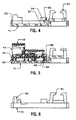
- Fig. 4 is a sectional view taken along line 4-4 of Fig. 2;
- Fig. 5 is a sectional view taken along line 5-5 of Fig. 2;
- Fig. 6 is a side view of the base;
- Fig. 7 is a front view of a modular connector;
- Fig. 8 is a perspective view of the connector of Fig. 7;
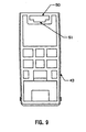
- Fig. 9 is a bottom view of the connector of Fig. 7;
- Fig. 10 is a sectional view of the connector of Fig. 7; and
- Fig. 11 is a rear view of the connector of Fig. 7;
-
- A connector receptacle box assembly embodying the concept of the present invention is designated generally by the
number 40 in the accompanying drawings. As seen in Figs. 1-6,assembly 40 includes a one-pieceplastic base 41 and a one-pieceplastic cover 42. Amodular communication connector 43, best seen in Figs. 1 and 7-11, is configured to be releasably mounted withinbase 41.Connector 43 includes a modularplug accepting socket 44 formed in the front face ofconnector 43. Also medially positioned adjacent the lower edge of the front face ofconnector 43 is a rectangular front mounting slot 46 (Fig. 1), a rear mounting slot 48 (Fig. 11), a T-shaped centralbottom mounting slot 50 having a centrally disposed notch 51 (Fig. 9).Connector 43 illustrates one type of connector configured to be mounted within the latching mechanism of the present invention although any type of connector, such as a coaxial connector, can be provided with latching features described herein for use in each respective embodiment of the present invention. -
Base 41 includes a plurality of laterally adjacent connector mounting features, each of which includes a spaced apart and opposedfront latch tooth 53 andrear latch tooth 54 which respectively are disposed to be received withinfront mounting slot 46 andrear mounting slot 48 ofconnector 43.Rear latch tooth 54 is medially disposed on alatch wall 55, projecting fromwall 55 at a right angle. Latchwall 55 is integrally formed at a right angle at the end of aresilient cantilever arm 57 formed in the floor ofbase 41 by a slot 58 (see Fig. 2).Cantilever arm 57 andlatch wall 55 resiliently positionrear latch tooth 54 such thatrear latch tooth 54 is resiliently cammed outwardly upon insertion ofconnector 43 into latching engagement withbase 41. Tolatch connector 43 withinbase 41,front latch tooth 53 inbase 41 is inserted intofront mounting slot 46 inconnector 43, andconnector 43 is rotated downwardly past resilientrear latch tooth 54 which is cammed outwardly until it is aligned withrear mounting slot 48 ofconnector 43 and is resiliently biased inwardly into slot 48 (see Fig. 5). The design of the singleresilient latch tooth 53 formed on alatch wall 55 carried on acantilever arm 57 integrally formed in abase 40 provides secure latching engagement of connector tobase 41 and allows miniature connector modules to be easily removed from thebase 41 merely by inserting a screwdriver betweenconnector 43 andlatch wall 55 and flexingwall 55 outwardly to disengagerear latch tooth 54 fromrear mounting slot 48. - As seen in Figs. 1 and 2,
base 41 is also formed withwire access apertures 59,mounting holes 60,wire positioning guides 61, andcover alignment flanges 62 forengaging cover 42.
Claims (2)
- A receptacle for mounting a modular connector having front and rear mounting slots disposed on front and back surfaces of the connector, comprising:characterized in thata planar base (41);latch means integrally formed in the base (41) for releasably securing the connector to the base including;a front latch tooth (53) formed in the base (41) disposed to engage the front mounting slot (46) of the connector (43), a resiliently mounted rear latch tooth (54) formed on a latch wall (55) and aligned with and spaced from the front latch tooth (53) such that the rear latch tooth (54) is disposed to engage the rear mounting slot (48) of the connector (43) secured by the latch means,
the latch wall (55) is formed perpendicular at the end of a resilient cantilever base arm (57) formed in the plane of the base (41), wherein the rear latch tooth (54) is disposed to resiliently latch the connector (43) to the base (41) such that the connector (43) can be released from the base by depressing the cantilever base arm (57), which rotates the latch wall (55) and latch tooth (54) away from the connector (43) to disengage the rear latch tooth (54) from the rear slot (48) in the connector. - A receptacle as set forth in claim 1, wherein the cantilever base arm (57) is defined in the base by a slot (58) formed in the base therearound.
Priority Applications (2)
| Application Number | Priority Date | Filing Date | Title |
|---|---|---|---|
| EP01116588A EP1143576B1 (en) | 1995-06-22 | 1996-06-20 | Connector mounting receptacles |
| EP07001417A EP1780845A1 (en) | 1995-06-22 | 1996-06-20 | Connector mounting receptacles |
Applications Claiming Priority (2)
| Application Number | Priority Date | Filing Date | Title |
|---|---|---|---|
| US08/493,439 US5672074A (en) | 1995-06-22 | 1995-06-22 | Connector mounting receptacles |
| US493439 | 1995-06-22 |
Related Child Applications (1)
| Application Number | Title | Priority Date | Filing Date |
|---|---|---|---|
| EP01116588A Division EP1143576B1 (en) | 1995-06-22 | 1996-06-20 | Connector mounting receptacles |
Publications (3)
| Publication Number | Publication Date |
|---|---|
| EP0750371A2 EP0750371A2 (en) | 1996-12-27 |
| EP0750371A3 EP0750371A3 (en) | 1998-05-27 |
| EP0750371B1 true EP0750371B1 (en) | 2002-01-23 |
Family
ID=23960228
Family Applications (3)
| Application Number | Title | Priority Date | Filing Date |
|---|---|---|---|
| EP01116588A Expired - Lifetime EP1143576B1 (en) | 1995-06-22 | 1996-06-20 | Connector mounting receptacles |
| EP96109972A Expired - Lifetime EP0750371B1 (en) | 1995-06-22 | 1996-06-20 | Connector mounting receptacles |
| EP07001417A Withdrawn EP1780845A1 (en) | 1995-06-22 | 1996-06-20 | Connector mounting receptacles |
Family Applications Before (1)
| Application Number | Title | Priority Date | Filing Date |
|---|---|---|---|
| EP01116588A Expired - Lifetime EP1143576B1 (en) | 1995-06-22 | 1996-06-20 | Connector mounting receptacles |
Family Applications After (1)
| Application Number | Title | Priority Date | Filing Date |
|---|---|---|---|
| EP07001417A Withdrawn EP1780845A1 (en) | 1995-06-22 | 1996-06-20 | Connector mounting receptacles |
Country Status (11)
| Country | Link |
|---|---|
| US (3) | US5672074A (en) |
| EP (3) | EP1143576B1 (en) |
| JP (2) | JP4309482B2 (en) |
| KR (1) | KR100414419B1 (en) |
| CN (3) | CN1106056C (en) |
| AU (1) | AU710335B2 (en) |
| BR (1) | BR9602819A (en) |
| CA (1) | CA2179669A1 (en) |
| DE (2) | DE69618718T2 (en) |
| MX (1) | MX9602372A (en) |
| TW (1) | TW313337U (en) |
Families Citing this family (35)
| Publication number | Priority date | Publication date | Assignee | Title |
|---|---|---|---|---|
| USD406563S (en) * | 1997-03-05 | 1999-03-09 | Hon Hai Precision Ind. Co., Ltd. | Electrical adapter |
| USD418481S (en) * | 1997-09-17 | 2000-01-04 | International Connectors And Cable Corporation | Surface mount box |
| ES2151832B1 (en) | 1998-08-04 | 2001-07-16 | Talgo Patentes | INSTALLATION FOR THE AUTOMATIC EVALUATION OF THE STATE OF THE BEARING BAND ON MOVING TRAIN WHEELS. |
| TW405762U (en) * | 1998-11-11 | 2000-09-11 | Molex Inc | Connector |
| USD425022S (en) * | 1999-03-30 | 2000-05-16 | Dieter Jaag | Data jack for surface mounting assembly |
| USD433385S (en) * | 1999-04-13 | 2000-11-07 | Adc Telecommunications, Inc. | Surface mount box |
| DE29908490U1 (en) * | 1999-05-12 | 1999-08-05 | Contact GmbH Elektrische Bauteile, 70565 Stuttgart | Holding system for different types of connectors |
| TW421307U (en) * | 1999-08-06 | 2001-02-01 | Hon Hai Prec Ind Co Ltd | Cable connector |
| USD450562S1 (en) | 2000-03-07 | 2001-11-20 | Adc Telecommunications, Inc. | Modular furniture adapter faceplate |
| DE10056474B4 (en) * | 2000-11-15 | 2004-10-28 | Epcos Ag | Housing, housing arrangement, electrolytic capacitor with the housing and arrangement of the electrolytic capacitor |
| USD485870S1 (en) | 2001-11-19 | 2004-01-27 | George P. Norman | Airplane shaped rocking apparatus |
| US6621724B1 (en) * | 2002-06-28 | 2003-09-16 | Pacific Carnetta, Inc. | Electrical power strip and plug for vehicle accessory |
| US20040209515A1 (en) * | 2003-04-03 | 2004-10-21 | Caveney Jack E. | High density patch panel |
| US7086872B2 (en) * | 2003-11-20 | 2006-08-08 | Tyco Electronics Corporation | Two piece surface mount header assembly having a contact alignment member |
| US20050151023A1 (en) * | 2003-12-16 | 2005-07-14 | Ribbe David J. | Control system for model aircraft |
| US7182649B2 (en) * | 2003-12-22 | 2007-02-27 | Panduit Corp. | Inductive and capacitive coupling balancing electrical connector |
| US7179131B2 (en) * | 2004-02-12 | 2007-02-20 | Panduit Corp. | Methods and apparatus for reducing crosstalk in electrical connectors |
| CN102082367B (en) | 2004-03-12 | 2013-11-20 | 泛达公司 | Methods and apparatus for reducing crosstalk in electrical connectors |
| US7153168B2 (en) * | 2004-04-06 | 2006-12-26 | Panduit Corp. | Electrical connector with improved crosstalk compensation |
| US7281957B2 (en) * | 2004-07-13 | 2007-10-16 | Panduit Corp. | Communications connector with flexible printed circuit board |
| EP1987569A1 (en) * | 2006-02-13 | 2008-11-05 | Panduit Corp. | Connector with crosstalk compensation |
| JP4772628B2 (en) * | 2006-09-12 | 2011-09-14 | 富士通株式会社 | Case, electronic device, and method of assembling the same |
| US7874878B2 (en) | 2007-03-20 | 2011-01-25 | Panduit Corp. | Plug/jack system having PCB with lattice network |
| US9106603B2 (en) | 2009-12-23 | 2015-08-11 | Synchronics plc | Apparatus, method and computer-readable storage mediums for determining application protocol elements as different types of lawful interception content |
| US8439702B2 (en) * | 2010-09-24 | 2013-05-14 | Ortronics, Inc. | High density jack |
| US8758065B2 (en) * | 2011-11-16 | 2014-06-24 | Panduit Corp. | High bandwidth jack with RJ45 backwards compatibility |
| DE102012102242B3 (en) * | 2012-03-16 | 2013-09-12 | Phoenix Contact Gmbh & Co. Kg | Arrangement as a modular distribution panel and method for its assembly |
| CN103296551A (en) * | 2013-04-27 | 2013-09-11 | 河南省电力公司信阳供电公司 | Socket |
| CN104617456B (en) * | 2015-02-13 | 2017-03-22 | 南车株洲电力机车有限公司 | Hanger bracket of vehicle end coupling |
| US10181735B2 (en) * | 2015-03-11 | 2019-01-15 | Norman R. Byrne | Portable electrical power unit |
| AU2016259450B2 (en) * | 2015-11-19 | 2021-11-04 | Schneider Electric (Australia) Pty Limited | Adapter for electrical and/or mechanical device |
| EP3387715B1 (en) | 2015-12-08 | 2021-05-12 | Panduit Corp. | Rj45 shuttered jacks and related communication systems |
| JP6672374B2 (en) * | 2018-05-08 | 2020-03-25 | 矢崎総業株式会社 | Lock structure, electrical junction box and wire harness |
| CN112217063B (en) * | 2020-10-14 | 2021-11-23 | 山东锦厚信息科技有限公司 | Socket convenient to install |
| CN216121059U (en) * | 2021-10-29 | 2022-03-22 | 宁德时代新能源科技股份有限公司 | Energy storage connector |
Family Cites Families (10)
| Publication number | Priority date | Publication date | Assignee | Title |
|---|---|---|---|---|
| FR1515834A (en) * | 1965-04-12 | 1968-03-08 | Bassani Spa | Three-pole switch |
| US3705377A (en) * | 1970-12-21 | 1972-12-05 | Bell Telephone Labor Inc | Receptacle for snap-in mounting of connectors |
| US3812281A (en) * | 1973-05-21 | 1974-05-21 | F Boyer | Locking assembly |
| US4406509A (en) * | 1981-11-25 | 1983-09-27 | E. I. Du Pont De Nemours & Co. | Jack and plug electrical assembly |
| US4477141A (en) * | 1982-11-19 | 1984-10-16 | At&T Technologies, Inc. | Tricoupler for modular wiring systems |
| JPH0511667Y2 (en) * | 1987-11-04 | 1993-03-23 | ||
| US4875881A (en) * | 1988-04-08 | 1989-10-24 | Panduit Corp. | Communication box assembly |
| US4883432A (en) * | 1988-12-28 | 1989-11-28 | The Siemon Company | Modular jack yoke |
| US5118310A (en) * | 1991-03-06 | 1992-06-02 | Panduit Corp. | Central latch modular telephone connector |
| US5161997A (en) * | 1991-10-11 | 1992-11-10 | Amp Incorporated | Hardwareless panel retention for shielded connector |
-
1995
- 1995-06-22 US US08/493,439 patent/US5672074A/en not_active Expired - Lifetime
-
1996
- 1996-06-11 AU AU55908/96A patent/AU710335B2/en not_active Ceased
- 1996-06-17 MX MX9602372A patent/MX9602372A/en unknown
- 1996-06-18 KR KR1019960021939A patent/KR100414419B1/en not_active Expired - Fee Related
- 1996-06-18 BR BR9602819A patent/BR9602819A/en not_active IP Right Cessation
- 1996-06-20 EP EP01116588A patent/EP1143576B1/en not_active Expired - Lifetime
- 1996-06-20 EP EP96109972A patent/EP0750371B1/en not_active Expired - Lifetime
- 1996-06-20 DE DE69618718T patent/DE69618718T2/en not_active Expired - Lifetime
- 1996-06-20 EP EP07001417A patent/EP1780845A1/en not_active Withdrawn
- 1996-06-20 DE DE69636873T patent/DE69636873T2/en not_active Expired - Lifetime
- 1996-06-21 CA CA002179669A patent/CA2179669A1/en not_active Abandoned
- 1996-06-21 CN CN96107120A patent/CN1106056C/en not_active Expired - Lifetime
- 1996-06-21 TW TW086203145U patent/TW313337U/en unknown
- 1996-06-21 JP JP16166796A patent/JP4309482B2/en not_active Expired - Fee Related
- 1996-06-21 CN CNB021199469A patent/CN1184726C/en not_active Expired - Lifetime
-
1997
- 1997-02-14 US US08/802,174 patent/US5738539A/en not_active Expired - Lifetime
- 1997-02-14 US US08/799,158 patent/US5766034A/en not_active Expired - Lifetime
-
2002
- 2002-05-10 CN CNB021199450A patent/CN1228889C/en not_active Expired - Fee Related
-
2004
- 2004-01-13 JP JP2004005075A patent/JP4091918B2/en not_active Expired - Fee Related
Also Published As
| Publication number | Publication date |
|---|---|
| JPH0917520A (en) | 1997-01-17 |
| EP1780845A1 (en) | 2007-05-02 |
| US5766034A (en) | 1998-06-16 |
| BR9602819A (en) | 1998-10-06 |
| DE69618718D1 (en) | 2002-03-14 |
| MX9602372A (en) | 1997-02-28 |
| JP4091918B2 (en) | 2008-05-28 |
| US5738539A (en) | 1998-04-14 |
| JP2004158459A (en) | 2004-06-03 |
| AU710335B2 (en) | 1999-09-16 |
| KR970004160A (en) | 1997-01-29 |
| JP4309482B2 (en) | 2009-08-05 |
| CA2179669A1 (en) | 1996-12-23 |
| DE69636873D1 (en) | 2007-03-15 |
| CN1228889C (en) | 2005-11-23 |
| AU5590896A (en) | 1997-01-09 |
| DE69618718T2 (en) | 2005-03-17 |
| KR100414419B1 (en) | 2004-04-30 |
| EP0750371A2 (en) | 1996-12-27 |
| EP1143576B1 (en) | 2007-01-24 |
| CN1381925A (en) | 2002-11-27 |
| CN1106056C (en) | 2003-04-16 |
| CN1144410A (en) | 1997-03-05 |
| CN1381926A (en) | 2002-11-27 |
| DE69636873T2 (en) | 2007-11-22 |
| CN1184726C (en) | 2005-01-12 |
| EP0750371A3 (en) | 1998-05-27 |
| EP1143576A1 (en) | 2001-10-10 |
| US5672074A (en) | 1997-09-30 |
| TW313337U (en) | 1997-08-11 |
Similar Documents
| Publication | Publication Date | Title |
|---|---|---|
| US5738539A (en) | Connector mounting receptacle | |
| US5612854A (en) | Computer power supply apparatus | |
| US6186825B1 (en) | Connector mounting system for modular wall panels | |
| EP1192835B1 (en) | Power and guidance connector | |
| US6450834B1 (en) | Panel mounting system for electrical connectors | |
| NL8902192A (en) | BUILT-IN CONNECTOR WITH A LOCKING FRAME. | |
| US5211585A (en) | Electrical connector housings having polarizing means | |
| US5197896A (en) | Float mounting an electrical connector | |
| CN1211348A (en) | Shielded electrical connector | |
| AU690276B2 (en) | Shielded connector assembly | |
| CN1985414A (en) | Dual Stack Connector | |
| WO2005004569A2 (en) | Improvements in adapter module retention latches | |
| CN101699665A (en) | Dual stacked connector | |
| JPH07296912A (en) | Electric connector assembly for flexible flat cable | |
| GB2305025A (en) | Electrical connector adapter | |
| JPH04233022A (en) | Female type electric connector having shield | |
| US4593960A (en) | Power entry connector | |
| US7059915B1 (en) | Panel mounted modular jack terminated to a circuit board | |
| US6012954A (en) | Electrical connector | |
| JPH0799706B2 (en) | Modular connector | |
| EP0074987B1 (en) | Electrical distribution system | |
| US5738540A (en) | Apparatus for coupling a device to an electrical receptacle | |
| AU724233B2 (en) | Connector mounting receptacles | |
| WO1998038715A1 (en) | Electrical outlet having panel mount latches | |
| KR100333842B1 (en) | Adapter with interchangeable plug board |
Legal Events
| Date | Code | Title | Description |
|---|---|---|---|
| PUAI | Public reference made under article 153(3) epc to a published international application that has entered the european phase |
Free format text: ORIGINAL CODE: 0009012 |
|
| AK | Designated contracting states |
Kind code of ref document: A2 Designated state(s): CH DE FR GB IT LI SE |
|
| PUAL | Search report despatched |
Free format text: ORIGINAL CODE: 0009013 |
|
| AK | Designated contracting states |
Kind code of ref document: A3 Designated state(s): CH DE FR GB IT LI SE |
|
| 17P | Request for examination filed |
Effective date: 19981005 |
|
| 17Q | First examination report despatched |
Effective date: 19991020 |
|
| RIC1 | Information provided on ipc code assigned before grant |
Free format text: 7H 01R 24/00 A, 7H 01R 13/74 B, 7H 01R 13/648 B, 7H 01R 13/518 B, 7H 01R 13/506 B, 7H 01R 13/73 B |
|
| GRAG | Despatch of communication of intention to grant |
Free format text: ORIGINAL CODE: EPIDOS AGRA |
|
| GRAG | Despatch of communication of intention to grant |
Free format text: ORIGINAL CODE: EPIDOS AGRA |
|
| GRAH | Despatch of communication of intention to grant a patent |
Free format text: ORIGINAL CODE: EPIDOS IGRA |
|
| GRAH | Despatch of communication of intention to grant a patent |
Free format text: ORIGINAL CODE: EPIDOS IGRA |
|
| GRAA | (expected) grant |
Free format text: ORIGINAL CODE: 0009210 |
|
| REG | Reference to a national code |
Ref country code: GB Ref legal event code: IF02 |
|
| AK | Designated contracting states |
Kind code of ref document: B1 Designated state(s): CH DE FR GB IT LI SE |
|
| REG | Reference to a national code |
Ref country code: CH Ref legal event code: EP |
|
| REF | Corresponds to: |
Ref document number: 69618718 Country of ref document: DE Date of ref document: 20020314 |
|
| REG | Reference to a national code |
Ref country code: CH Ref legal event code: NV Representative=s name: ISLER & PEDRAZZINI AG |
|
| ET | Fr: translation filed | ||
| PG25 | Lapsed in a contracting state [announced via postgrant information from national office to epo] |
Ref country code: SE Free format text: LAPSE BECAUSE OF NON-PAYMENT OF DUE FEES Effective date: 20020621 |
|
| PG25 | Lapsed in a contracting state [announced via postgrant information from national office to epo] |
Ref country code: LI Free format text: LAPSE BECAUSE OF NON-PAYMENT OF DUE FEES Effective date: 20020630 Ref country code: CH Free format text: LAPSE BECAUSE OF NON-PAYMENT OF DUE FEES Effective date: 20020630 |
|
| PLBE | No opposition filed within time limit |
Free format text: ORIGINAL CODE: 0009261 |
|
| STAA | Information on the status of an ep patent application or granted ep patent |
Free format text: STATUS: NO OPPOSITION FILED WITHIN TIME LIMIT |
|
| 26N | No opposition filed | ||
| EUG | Se: european patent has lapsed | ||
| REG | Reference to a national code |
Ref country code: CH Ref legal event code: PL |
|
| PG25 | Lapsed in a contracting state [announced via postgrant information from national office to epo] |
Ref country code: IT Free format text: LAPSE BECAUSE OF NON-PAYMENT OF DUE FEES;WARNING: LAPSES OF ITALIAN PATENTS WITH EFFECTIVE DATE BEFORE 2007 MAY HAVE OCCURRED AT ANY TIME BEFORE 2007. THE CORRECT EFFECTIVE DATE MAY BE DIFFERENT FROM THE ONE RECORDED. Effective date: 20050620 |
|
| PGFP | Annual fee paid to national office [announced via postgrant information from national office to epo] |
Ref country code: DE Payment date: 20130627 Year of fee payment: 18 |
|
| PGFP | Annual fee paid to national office [announced via postgrant information from national office to epo] |
Ref country code: FR Payment date: 20130702 Year of fee payment: 18 |
|
| REG | Reference to a national code |
Ref country code: DE Ref legal event code: R119 Ref document number: 69618718 Country of ref document: DE |
|
| REG | Reference to a national code |
Ref country code: FR Ref legal event code: ST Effective date: 20150227 |
|
| REG | Reference to a national code |
Ref country code: DE Ref legal event code: R119 Ref document number: 69618718 Country of ref document: DE Effective date: 20150101 |
|
| PG25 | Lapsed in a contracting state [announced via postgrant information from national office to epo] |
Ref country code: DE Free format text: LAPSE BECAUSE OF NON-PAYMENT OF DUE FEES Effective date: 20150101 |
|
| PG25 | Lapsed in a contracting state [announced via postgrant information from national office to epo] |
Ref country code: FR Free format text: LAPSE BECAUSE OF NON-PAYMENT OF DUE FEES Effective date: 20140630 |
|
| PGFP | Annual fee paid to national office [announced via postgrant information from national office to epo] |
Ref country code: GB Payment date: 20150629 Year of fee payment: 20 |
|
| REG | Reference to a national code |
Ref country code: GB Ref legal event code: PE20 Expiry date: 20160619 |
|
| PG25 | Lapsed in a contracting state [announced via postgrant information from national office to epo] |
Ref country code: GB Free format text: LAPSE BECAUSE OF EXPIRATION OF PROTECTION Effective date: 20160619 |