EP0750109A2 - Pumpenvorrichtung - Google Patents
Pumpenvorrichtung Download PDFInfo
- Publication number
- EP0750109A2 EP0750109A2 EP96304348A EP96304348A EP0750109A2 EP 0750109 A2 EP0750109 A2 EP 0750109A2 EP 96304348 A EP96304348 A EP 96304348A EP 96304348 A EP96304348 A EP 96304348A EP 0750109 A2 EP0750109 A2 EP 0750109A2
- Authority
- EP
- European Patent Office
- Prior art keywords
- fuel
- pressure pump
- adjustable orifice
- engine
- orifice
- Prior art date
- Legal status (The legal status is an assumption and is not a legal conclusion. Google has not performed a legal analysis and makes no representation as to the accuracy of the status listed.)
- Withdrawn
Links
Images
Classifications
-
- F—MECHANICAL ENGINEERING; LIGHTING; HEATING; WEAPONS; BLASTING
- F02—COMBUSTION ENGINES; HOT-GAS OR COMBUSTION-PRODUCT ENGINE PLANTS
- F02M—SUPPLYING COMBUSTION ENGINES IN GENERAL WITH COMBUSTIBLE MIXTURES OR CONSTITUENTS THEREOF
- F02M59/00—Pumps specially adapted for fuel-injection and not provided for in groups F02M39/00 -F02M57/00, e.g. rotary cylinder-block type of pumps
- F02M59/20—Varying fuel delivery in quantity or timing
- F02M59/34—Varying fuel delivery in quantity or timing by throttling of passages to pumping elements or of overflow passages, e.g. throttling by means of a pressure-controlled sliding valve having liquid stop or abutment
-
- F—MECHANICAL ENGINEERING; LIGHTING; HEATING; WEAPONS; BLASTING
- F02—COMBUSTION ENGINES; HOT-GAS OR COMBUSTION-PRODUCT ENGINE PLANTS
- F02M—SUPPLYING COMBUSTION ENGINES IN GENERAL WITH COMBUSTIBLE MIXTURES OR CONSTITUENTS THEREOF
- F02M41/00—Fuel-injection apparatus with two or more injectors fed from a common pressure-source sequentially by means of a distributor
- F02M41/08—Fuel-injection apparatus with two or more injectors fed from a common pressure-source sequentially by means of a distributor the distributor and pumping elements being combined
- F02M41/14—Fuel-injection apparatus with two or more injectors fed from a common pressure-source sequentially by means of a distributor the distributor and pumping elements being combined rotary distributor supporting pump pistons
- F02M41/1405—Fuel-injection apparatus with two or more injectors fed from a common pressure-source sequentially by means of a distributor the distributor and pumping elements being combined rotary distributor supporting pump pistons pistons being disposed radially with respect to rotation axis
- F02M41/1411—Fuel-injection apparatus with two or more injectors fed from a common pressure-source sequentially by means of a distributor the distributor and pumping elements being combined rotary distributor supporting pump pistons pistons being disposed radially with respect to rotation axis characterised by means for varying fuel delivery or injection timing
- F02M41/1427—Arrangements for metering fuel admitted to pumping chambers, e.g. by shuttles or by throttle-valves
-
- F—MECHANICAL ENGINEERING; LIGHTING; HEATING; WEAPONS; BLASTING
- F02—COMBUSTION ENGINES; HOT-GAS OR COMBUSTION-PRODUCT ENGINE PLANTS
- F02M—SUPPLYING COMBUSTION ENGINES IN GENERAL WITH COMBUSTIBLE MIXTURES OR CONSTITUENTS THEREOF
- F02M59/00—Pumps specially adapted for fuel-injection and not provided for in groups F02M39/00 -F02M57/00, e.g. rotary cylinder-block type of pumps
- F02M59/44—Details, components parts, or accessories not provided for in, or of interest apart from, the apparatus of groups F02M59/02 - F02M59/42; Pumps having transducers, e.g. to measure displacement of pump rack or piston
- F02M59/48—Assembling; Disassembling; Replacing
Definitions
- This invention relates to a fuel injection pumping apparatus for supplying fuel to an internal combustion engine and of the kind comprising a high pressure pump operable in timed relationship with the associated engine to deliver fuel to the engine cylinders in turn, a low pressure pump for supplying fuel to the high pressure pump during the filling periods thereof and flow control means including an adjustable orifice for varying the amount of fuel which is supplied to the high pressure pump, said flow control means further including means for adjusting said orifice.
- the high pressure pump comprises a pair of plungers housed in a diametrically disposed bore formed in a rotary distributor member which is arranged to be driven in timed relationship with the associated engine.
- the plungers are moved inwardly by the action of cam lobes formed on the internal peripheral surface of an annular cam ring and the fuel displaced from the bore is delivered to one of a plurality of outlet ports formed in a body part which houses the distributor member.
- the low pressure pump is a vane pump the rotary part of which is coupled to the distributor member and the inlet and outlet of the pump are interconnected by a relief valve.
- the flow control means comprises an angularly adjustable throttle member in which is formed a groove positioned to communicate with a port formed in the wall of a cylinder in which the throttle member is mounted.
- the groove and port form the adjustable orifice and the degree of restriction offered by the orifice depends upon the angular setting of the throttle member.
- the angular setting of the throttle member can be determined by a mechanical governor or the throttle member may be coupled to an electromagnetic actuator, the supply of current to which and hence the setting of the throttle member, is controlled by an electronic governor. In each case there is provision for an operator controlled input to the governor whereby the amount of fuel supplied to the associated engine can be adjusted.
- the object of the invention is to provide an apparatus of the kind specified in a simple and convenient form.
- an apparatus of the kind specified includes a further adjustable orifice connected in series with said flow control means.
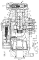
- the pumping apparatus comprises a body part 12 within which is located a fixed sleeve 13 and rotatably mounted in the sleeve 13 is a rotary distributor member 14.
- the distributor member is coupled to a drive shaft 15 which extends to the exterior of a casing 16, the drive shaft in use being arranged to be driven in timed relationship with the associated engine.
- the body part 12 is secured within the open end of the casing 16.
- the distributor member 14 is provided with an enlarged portion adjacent one end of the sleeve 13 and in which is formed a diametrically disposed bore 17 in which is located a pair of pumping plungers 18. At their outer ends the plungers are engaged by cam followers which include rollers 19 and these are engageable by cam lobes formed on the internal peripheral surface of an annular cam ring 20.
- the cam ring is angularly adjustable about the axis of rotation of the distributor member by means of a piston 21 housed within a cylinder 22.
- the piston is coupled to the cam ring by means of a peg 23.
- an axially extending passage 24 which communicates with the bore 17 intermediate the plungers and it also communicates with a radially extending delivery passage 25 which opens onto the periphery of the distributor member so that it can communicate in turn with a plurality of outlet ports 26 which in use, are connected to the injection nozzles respectively of the associated engine.
- the communication between the delivery passage and an outlet port is arranged to occur during the time when the plungers 18 are moved inwardly by the cam lobes.
- the passage 24 also communicates with a plurality of inlet passages 27 which extend to the periphery of the distributor member and which are arranged to register in turn with an inlet port 28 formed in the sleeve 13.
- the port 28 communicates with a passage 29 formed in the body part and this passage defines a port 30 in the wall of a cylinder 31 formed in the body part.
- a low pressure fuel supply pump of the vane type the rotor 35 of which is driven by the distributor member.
- the low pressure pump has an inlet 36 which communicates with a fuel inlet 37 connected in use to a source of fuel.
- the inlet and outlet of the low pressure pump are interconnected by a relief valve which controls the output pressure of the low pressure pump in a manner so that it varies with the speed at which the apparatus is driven.
- the outlet 34 of the low pressure pump is connected to one end of the cylinder 22 which houses the piston 21 and in the opposite end of this cylinder there is located a spring which biasses the piston in opposition to the force generated by the fuel pressure.
- a spring which biasses the piston in opposition to the force generated by the fuel pressure.
- an anti-shock valve 39 Located in the passage leading to the cylinder is an anti-shock valve 39.
- the amount of fuel supplied depends upon the angular setting of the throttle member 32. As the distributor member continues to rotate the inlet passage 27 will move out of register with the inlet port 28 and the delivery passage 25 will move into register with one of the outlet ports 26. Further rotation of the distributor member will cause the plungers to be moved inwardly by the inter-action of the rollers 19 with the leading flanks of the cam lobes, the position of the distributor member at which such inward movement takes place depending upon the amount of fuel which has been supplied to the bore 17. As the plungers are moved inwardly fuel is delivered to one of the outlet ports and is supplied to the respective injection nozzle of the associated engine.
- the governor mechanism 11 includes a plurality of centrifugal weights 40 which are housed in a cage 41 mounted on and driven by the drive shaft.
- the weights 40 have toe portions engageable with a thrust member carried by an axially moveable sleeve 42 mounted on the drive shaft.
- a governor lever 43 is pivotally mounted intermediate its ends and one end of the lever engages the sleeve 42 and the opposite end is coupled to one end of a governor spring 44 the opposite end of which is connected to an arm mounted on an angularly adjustable control member 45 the position of which is determined by the engine operator.
- the other end of the lever 43 is connected by a link 46 to an arm carried by the throttle member 32.
- the weights 40 move outwardly and effect axial movement of the sleeve 42.
- This movement of the sleeve results in pivotal movement of the arm 43 against the action of the spring 44 and by way of the link 46 results in angular adjustment of the throttle member in a direction to reduce the effective size of the orifice constituted by the groove 33 and the port 30.
- the amount of fuel which is delivered to the associated engine is reduced and the speed of the engine settles to a governed value. If the speed of the associated engine falls the force exerted by the weights 40 is reduced and the arm 43 moves in the opposite direction to effect an increase in the amount of fuel which is supplied to the associated engine. If the control member 45 is moved to increase the force exerted by the spring 44 the governor weights are moved inwardly and an increased amount of fuel is supplied to the associated engine resulting in an increasing engine speed and vice versa.
- the throttle valve 32 together with the groove 33 and the port 30 are collectively indicated at 48 and the low pressure pump and relief valve are collectively indicated at 47.
- manufacturing tolerances result in performance differences between individual pumps.
- a further adjustable orifice 49 is disposed intermediate the low pressure pump and the throttle valve.
- the complete assembly is tested and the size of the further orifice 49 adjusted so that the amount of fuel delivered by the apparatus at a particular speed and for a particular setting of the operator adjustable member 45 corresponds to a desired value.
- This adjustment is preferably carried out at the peak torque fuel level of the engine which is to be supplied with fuel.
- the further adjustable orifice 49 is not intended to be adjusted in the use of the apparatus and may have a number of forms such for example, as a taper needle valve, an orifice plate or a screw in plug.
- Adjustment of the further adjustable orifice as described enables the sensitivity of the throttle valve to be varied and such adjustment also controls the governor droop, this normally being varied or adjusted by altering the rate of the governor spring 44.
- This adjustment has no effect on the maximum amount of fuel which can be supplied by the apparatus to the associated engine, this being determined by adjustable stops which limit the outward movement of the pumping plungers. Such stops are shown at 50 in Figure 1.
- the mechanical governor 11 may be replaced by an electronic governor in which the angular setting of the throttle valve is determined by an electromagnetic actuator.
- the flow of electric current in the winding of the actuator is controlled by an electronic control system responsive to the engine speed and having an input from an operator adjustable control.
- the effect of providing the further adjustable orifice 49 is to enable matching of the completed assemblies to be carried out and this enables the customer to be supplied with assemblies which are more consistent so far as the governing function is concerned.
- An apparatus of the general type as shown in Figure 1 will in practice be provided with an electrically operated stop valve which is incorporated in the fuel flow line between the outlet 34 of the low pressure pump and the throttle valve.
- the stop valve is biased to the closed position and is held open by electric current which is supplied when the key operable switch of the vehicle is turned to the start and run positions.
- the throttle valve is biased by a spring into engagement with an adjustable stop so that it can serve as the further adjustable orifice.
- the stop valve is replaced by an electrically controlled variable orifice valve which would be powered by an electronic control system.
- the pumping apparatus may be provided with a so called torque control.
- a so called torque control is intended to provide a limit to the maximum amount of fuel which can be supplied to the associated engine. This limit may vary with engine speed and will vary as the pressure at which air is supplied to the engine varies.
- the torque control mechanism may incorporate an adjustable orifice which is connected in series with the throttle valve and the further adjustable orifice can be used to provide the required final setting of the pumping apparatus.
Landscapes
- Engineering & Computer Science (AREA)
- Chemical & Material Sciences (AREA)
- Combustion & Propulsion (AREA)
- Mechanical Engineering (AREA)
- General Engineering & Computer Science (AREA)
- High-Pressure Fuel Injection Pump Control (AREA)
- Fuel-Injection Apparatus (AREA)
Applications Claiming Priority (2)
| Application Number | Priority Date | Filing Date | Title |
|---|---|---|---|
| GBGB9512362.6A GB9512362D0 (en) | 1995-06-17 | 1995-06-17 | Pumping apparatus |
| GB9512362 | 1995-06-17 |
Publications (2)
| Publication Number | Publication Date |
|---|---|
| EP0750109A2 true EP0750109A2 (de) | 1996-12-27 |
| EP0750109A3 EP0750109A3 (de) | 1997-10-08 |
Family
ID=10776243
Family Applications (1)
| Application Number | Title | Priority Date | Filing Date |
|---|---|---|---|
| EP96304348A Withdrawn EP0750109A3 (de) | 1995-06-17 | 1996-06-10 | Pumpenvorrichtung |
Country Status (2)
| Country | Link |
|---|---|
| EP (1) | EP0750109A3 (de) |
| GB (1) | GB9512362D0 (de) |
Family Cites Families (3)
| Publication number | Priority date | Publication date | Assignee | Title |
|---|---|---|---|---|
| US4351283A (en) * | 1981-05-01 | 1982-09-28 | General Motors Corporation | Diesel fuel injection pump secondary fuel metering control system |
| ES8605076A1 (es) * | 1985-04-16 | 1986-03-16 | Cav Condiesel Sa | Perfeccionamientos en las bombas rotativas de inyeccion |
| SU1268764A1 (ru) * | 1985-06-10 | 1986-11-07 | Ленинградский Ордена Ленина Политехнический Институт Им.М.И.Калинина | Силова установка |
-
1995
- 1995-06-17 GB GBGB9512362.6A patent/GB9512362D0/en active Pending
-
1996
- 1996-06-10 EP EP96304348A patent/EP0750109A3/de not_active Withdrawn
Also Published As
| Publication number | Publication date |
|---|---|
| GB9512362D0 (en) | 1995-08-16 |
| EP0750109A3 (de) | 1997-10-08 |
Similar Documents
| Publication | Publication Date | Title |
|---|---|---|
| EP0643221B1 (de) | Kraftstoffzufuhreinrichtung | |
| US6872056B2 (en) | Radial piston pump for producing high fuel pressure, as well as method for operating an internal combustion engine, computer program, and control and/or regulating unit | |
| US4407250A (en) | Fuel injection system | |
| PL81286B1 (de) | ||
| US2965087A (en) | Fuel injection pump | |
| US3648673A (en) | Fuel injection pump | |
| GB2076078A (en) | A fuel injection pump | |
| GB2076075A (en) | A fuel injection pump for internal combustion engines | |
| US4499883A (en) | Distributor type fuel-injection pump for distributing fuel to cylinders of an internal combustion engine | |
| US4552117A (en) | Fuel injection pump with spill control mechanism | |
| US4426983A (en) | Liquid fuel pumping apparatus | |
| GB2086080A (en) | Control of fuel supply in i.c. engines | |
| US4345563A (en) | Fuel injection pump for internal combustion engines | |
| EP0750109A2 (de) | Pumpenvorrichtung | |
| EP0118385B1 (de) | Kraftstoffeinspritzpumpe mit Kolbenhubsteuerung | |
| GB2058947A (en) | Fuel pumping apparatus | |
| US5203303A (en) | Fuel pumping apparatus | |
| US3024779A (en) | Timing device for fuel injection pump | |
| US5220894A (en) | Fuel injection pump for internal combustion engines | |
| GB2196153A (en) | Fuel system for a multi-cylinder engine | |
| US4793311A (en) | Fuel injection pump with multi-state load/speed control system | |
| US4751903A (en) | Fuel pumping apparatus | |
| US4644924A (en) | Fuel injection pump with spill control mechanism | |
| US5535721A (en) | Fuel pump | |
| US5161509A (en) | Fuel injection pump |
Legal Events
| Date | Code | Title | Description |
|---|---|---|---|
| PUAI | Public reference made under article 153(3) epc to a published international application that has entered the european phase |
Free format text: ORIGINAL CODE: 0009012 |
|
| AK | Designated contracting states |
Kind code of ref document: A2 Designated state(s): DE ES FR GB IT |
|
| PUAL | Search report despatched |
Free format text: ORIGINAL CODE: 0009013 |
|
| AK | Designated contracting states |
Kind code of ref document: A3 Designated state(s): DE ES FR GB IT |
|
| STAA | Information on the status of an ep patent application or granted ep patent |
Free format text: STATUS: THE APPLICATION IS DEEMED TO BE WITHDRAWN |
|
| 18D | Application deemed to be withdrawn |
Effective date: 19980409 |