EP0749239A2 - Method and device for supplementary data transmission in TV channels - Google Patents
Method and device for supplementary data transmission in TV channels Download PDFInfo
- Publication number
- EP0749239A2 EP0749239A2 EP96107459A EP96107459A EP0749239A2 EP 0749239 A2 EP0749239 A2 EP 0749239A2 EP 96107459 A EP96107459 A EP 96107459A EP 96107459 A EP96107459 A EP 96107459A EP 0749239 A2 EP0749239 A2 EP 0749239A2
- Authority
- EP
- European Patent Office
- Prior art keywords
- signal
- additional data
- data
- signals
- additional
- Prior art date
- Legal status (The legal status is an assumption and is not a legal conclusion. Google has not performed a legal analysis and makes no representation as to the accuracy of the status listed.)
- Granted
Links
Images


Classifications
-
- H—ELECTRICITY
- H04—ELECTRIC COMMUNICATION TECHNIQUE
- H04N—PICTORIAL COMMUNICATION, e.g. TELEVISION
- H04N7/00—Television systems
- H04N7/08—Systems for the simultaneous or sequential transmission of more than one television signal, e.g. additional information signals, the signals occupying wholly or partially the same frequency band, e.g. by time division
- H04N7/087—Systems for the simultaneous or sequential transmission of more than one television signal, e.g. additional information signals, the signals occupying wholly or partially the same frequency band, e.g. by time division with signal insertion during the vertical blanking interval only
- H04N7/088—Systems for the simultaneous or sequential transmission of more than one television signal, e.g. additional information signals, the signals occupying wholly or partially the same frequency band, e.g. by time division with signal insertion during the vertical blanking interval only the inserted signal being digital
-
- H—ELECTRICITY
- H04—ELECTRIC COMMUNICATION TECHNIQUE
- H04N—PICTORIAL COMMUNICATION, e.g. TELEVISION
- H04N7/00—Television systems
- H04N7/08—Systems for the simultaneous or sequential transmission of more than one television signal, e.g. additional information signals, the signals occupying wholly or partially the same frequency band, e.g. by time division
- H04N7/084—Systems for the simultaneous or sequential transmission of more than one television signal, e.g. additional information signals, the signals occupying wholly or partially the same frequency band, e.g. by time division with signal insertion during the horizontal blanking interval only
- H04N7/085—Systems for the simultaneous or sequential transmission of more than one television signal, e.g. additional information signals, the signals occupying wholly or partially the same frequency band, e.g. by time division with signal insertion during the horizontal blanking interval only the inserted signal being digital
Definitions
- the invention relates to a method of the type defined in more detail in the preamble of claim 1 and a device of the type described in the preamble of claim 3, with the aid of which it is possible to transmit additional data via a TV channel.
- Such methods and devices are e.g. B. for audio data known from Gassmann / Eckert: "Das COM-System", Funkschau 1970, issue 20, pages 689 to 692 and issue 21, pages 749 to 750 and for video data from Langenkamp / Löwy: "Megatext-IC for teletext and Graphic "RFE 1994 Issue 7, pages 18 to 20.
- CVBS signal color, image, deflection and synchronous signal
- additional data further information-carrying signals
- Radio satellite technology enables the reception of an ever increasing number of television programs, but does not offer local program providers opportunities for regional services because of the large coverage areas and the high costs.
- Broadband communication networks are for portable devices and receiving points with large distances unsuitable.
- the terrestrial transmitter network infrastructure already contains test lines and teletext predominantly in the image-free lines. Additional wireless services often fail due to high costs for television studios and frequency scarcity.
- the invention has set itself the task of using the unused channel capacity of the TV channel even more optimally and thereby high transmission security, high transmission rates, high system variability, interference-free reception of the TV program, the superimposition of additional data without technical intervention in the TV transmitter modules and to ensure the compatibility of existing TV sets for PALplus, NTSC and SECAM.
- this method is suitable for an additional implementation in computers, which can also be equipped with TV reception cards for multimedia purposes.
- a suitable device for a hardware implementation which is suitable as an additive for existing transmitters and receivers of the picture broadcasting network, describes the characterizing part of patent claim 3.
- the information-carrying signals for the additional data transmission are combined with a superimposition circuit in such a way that signals can be programmed to be positioned in all color and image signal-free periods.
- the additional data transmission system has a number of advantages. By selecting with counting and evaluating, when deciding on the use of the time periods for the additional data transmission, it can be configured in such a way that no interference occurs when the television broadcast is received.
- the superimposition and reception of the information-carrying additional data signals can be carried out using small, inexpensive additional devices. If necessary, the transmission rate can be adapted to the conditions of the real channel by programming.
- the additional data transmission is realized with signal levels of less than 20 mV, which ensures the compatibility of standard TV sets.
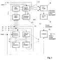
- FIG. 1 shows the data-controlled line-selective spreading sequence generator 11, which outputs a spreading sequence signal sp and a spreading permission signal se (FIGS. 3 and 4), which is converted in the digital-to-analog converter 8 into a three-value additional data signal of the levels 0, + and -.
- the non-band-limited additional data signal contained at the output of the digital-to-analog converter 8 is limited to the video bandwidth by the effect of the transmission filter 9 and is superimposed in the adder 10 with the CVBS signal of the first or another line type.
- the data-controlled line-selective spreading sequence generator 11 is controlled by the data to be transmitted, which are called up by the data clock stored in the signal EPROM 3.2, and by the time control signals image pulse BI, line pulse ZI and the system clock ST of the transmitter synchronization 12.
- the image pulse BI occurs at the beginning of each image, the time pulse ZI at the beginning of each line.
- the image pulse frequency and the system clock frequency are coupled to one another in a phase-locked manner.
- the lines from 0 to 624 are counted in the line counter. Since a number of lines have a similar structure with regard to the additional data signals to be introduced, the line number by the line type EPROM 3.2 addresses the address area of the signal EPROM 3.1, which generates a signal insertion that fits into the respective line structure.
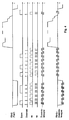
- the signals for six data symbols, the signals for three data symbols and the signal for a data symbol are inserted on the front porch in the bottom of the synchronizing pulse.
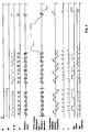
- the signals for six data symbols are on in the bottom of the synchronizing pulse inserted the signals for eight data symbols on the back porch and the signal for data symbol on the front porch. Since a number of lines have identical structures, identical signal structures can be stored in the signal EPROM 3.1 for these lines.
- the system clock edges ST are counted in time by the clock counter, e.g. B. 576 bars per line. With the system clock ST and the selection of the line type ZT, the signals spreader permission se, spread signal sp and data clock previously stored in the signal EPROM 3.1 are read out in time from the system clock edge for system clock edge and are fed to the digital-analog converter 8.
- transmitter synchronization is a synchronous processor, e.g. B. the circuit TDA 9257, which derives a processor clock of 27 MHz, a horizontal signal HS and a vertical signal VS with a jitter of less than 5 ns for further processing from the CVBS signal.
- a synchronous processor e.g. B. the circuit TDA 9257, which derives a processor clock of 27 MHz, a horizontal signal HS and a vertical signal VS with a jitter of less than 5 ns for further processing from the CVBS signal.
- the signals BI, ZI and ST stand for the adaptation between the output speed the data source whose data is to be transmitted and the data clock of the data-controlled line-selective spreading sequence generator with, for example, a FIFO circuit.
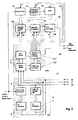
- FIG. 2 shows the additional data receiver to be operated at the receiving end, the processing of the signals in the receiver and the signals for controlling the same being shown in FIG. 5 for the first line type and in FIG. 6 for another line type.
- This additional data receiver consists of the receiver synchronization 21, the line-selective reference spreading sequence generator 20 and the analog input part, which in turn is composed of clamping 13, limiter amplifier / offset correction 14, analog-digital converter 14 and the digital correlator 19.
- Clamping can be activated by counting the clock edges in the line using clock counter 1 and reading out the corresponding memory content from the control and signal EPROM 3.1.
- the limiter amplifier 14 amplifies, limits and offset corrects in such a way that the converter area of the subsequent ADC is optimally used while the additional data signals are present without overdriving can (Fig. 5 and 6).
- This offset correction is controlled with the offset correction signal ok read from the control and signal EPROM 3.1.
- the sequence of the samples reaches the digital multiplier 16 in a certain word width, where the output signal of the limiter amplifier is multiplied in digital form by the reference signal in the form of the supplied signals spreader permission se and spreading sequence sp.
- the product is subsequently integrated by the digital integrator 17.
- the integration result can be seen in an analogous representation in FIGS. 5 and 6.
- the integrator is released by the integration permission ie read from the control and signal EPROM 3.1, the reset by the integrator reset ir and the decision by the takeover pulse ü.
- the row-selective reference spreading sequence generator 20 corresponds to the data-controlled row-selective spreading sequence generator 11.
- the signals BI, ZI and ST stand for the adaptation of the data output speed of the additional data receiver to the data clock of the subsequent data sink, for example with a FIFO Circuit available.
- the signals image pulse BI, line pulse ZI and system clock ST are obtained from the composite signal by the interaction of the synchronous processor 4, the divider for system clock 6, the image pulse detector 5 and the line pulse detector 7, whereby an exact positioning of the Additional data signal within the entire TV picture with an accuracy of less than 5 ns is made possible.
- the data-controlled line-selective spreading sequence generator 20 can use the signals image pulse BI, line pulse ZI and system clock ST, a line counter 2 and a clock counter 1, the entire TV picture with a time grid of z. B. 111, ns are fully addressed, which means that the additional data signals can be selected as required or programmable via EPROM, into which the TV picture structure can be fitted. If the line type is selected via the line counter 2 with the aid of a line type EPROM 3.2, the amount of memory for the signal part of the signal and control EPROM 3.1 can be considerably reduced.
- the signals image pulse BI, line pulse ZI and system clock ST are generated from the composite signal by the interaction of the synchronous processor 4, the divider for system clock 6, the image pulse detector 5 and the line pulse detector 7, as a result of which an exact temporal positioning of the reference signal for correlation reception within the entire TV picture with an accuracy of less than 5 ns.
- the entire TV picture can be completely addressed in the line-selective reference spreading sequence generator, as a result of which the additional data signals can be selected as desired or can be programmed via EPROM in the TV picture Structure can be received by the digital correlation receiver 19.
- control signals clamping pulse ki, offset compensation ok, system clock for AD conversion, spreading permission se, spreading signal sp, integration permission ie, integrator reset ir and takeover ü, which are required for the input stages, the ADC and digital correlation receiver, are generated with the same precision.
- the clamping 13, which is ensured by means of an exact time control by the clamping pulse ki, enables the optimal processing of the mixture of composite signal and additional data signal.
- the limiter amplifier / offset compensation 14 amplifies this mixture in the input stages so that during the sync pulse the CVBS level, controlled by the offset compensation signal, is raised to the mean value of 0 volts. Depending on the level of the additional data signals, amplification takes place here in such a way that the ADC input converter area, including possible noise disturbances, is optimally utilized.
- the limitation of the amplifier protects the ADC from destruction in times when chrominance and luminance are transmitted.
- the additional data is transmitted using biphase signals, so that a transmission with a low error rate with additional data signal levels of a few mV is possible when receiving, even with inaccurate clamping and offset compensation, by averaging as a result of integration.
- the programmability of the additional data transmission system allows easy adaptation to SECAM, NTSC, PAL and PALplus.
- the signals image pulse BI, line pulse ZI and system clock ST are available both on the transmitting side and on the receiving side for speed adjustments between the source and the transmission system or transmission system and the sink as well as for frame and superframe synchronization.
Abstract
Description
Die Erfindung bezieht sich auf ein Verfahren der im Oberbegriff des Patentanspruchs 1 näher definierten Art und eine Vorrichtung der Oberbegriff des Patentanspruchs 3 beschriebenen Art mit deren Hilfe es möglich ist, über einen TV-Kanal zusätzliche Daten zu übertragen. Solche Verfahren und Vorrichtungen sind z. B. für Audiodaten bekannt aus Gassmann/Eckert: "Das COM-System", Funkschau 1970, Heft 20, Seiten 689 bis 692 und Heft 21, Seiten 749 bis 750 und für Videodaten aus Langenkamp/Löwy: "Megatext-IC für Videotext und Grafik" RFE 1994 Heft 7, Seiten 18 bis 20.The invention relates to a method of the type defined in more detail in the preamble of
Die Eigenschaften des FBAS-Signales (Farb-, Bild-, Ablenk- und Synchronsignal) lassen die Möglichkeit offen, weitere informationstragende Signale (Zusatzdaten) zu überlagern, wobei der Empfang des TV-Rundfunkprogramms nicht gestört werden darf. Während sich die meisten Veröffentlichungen nur mit einer Art von Zusatzdaten befassen, ist z. B. in Rudolf Meusel: "Fernsehtechnik", Hüttig 1991, im 9. Kapitel auf den Seiten 210 bis 227 die Übertragung mehrerer zusätzlicher Prüf- und Datensignale beschrieben. Die Übertragung der Zusatzdaten erfolgt mit hoher Übertragungssicherheit und einer möglichst hohen Übertragungsrate.The properties of the CVBS signal (color, image, deflection and synchronous signal) leave open the possibility of superimposing further information-carrying signals (additional data), whereby the reception of the TV broadcasting program must not be disturbed. While most publications only deal with one type of additional data, e.g. B. in Rudolf Meusel: "Fernsehtechnik", Hüttig 1991, in the 9th chapter on pages 210 to 227 describes the transmission of several additional test and data signals. The additional data is transmitted with high transmission security and the highest possible transmission rate.
Die Rundfunksatellitentechnik ermöglicht zwar den Empfang einer immer größeren Zahl von Fernsehprogrammen, bietet aber lokalen Programmanbietern wegen der großen Ausleuchtzonen und der hohen Kosten keine Möglichkeiten für regionale Dienste. Breitbandkommunikationsnetze sind dagegen für portable Geräte und Empfangsstellen mit großen Abständen ungeeignet. Die terrestrische Sendernetzinfrastruktur enthält bereits überwiegend in den bildfreien Zeilen Prüfzeilen und Videotext. Drahtlose Zusatzdienste scheitern vielfach an zu hohen Kosten für Fernsehstudios und Frequenzknappheit.Radio satellite technology enables the reception of an ever increasing number of television programs, but does not offer local program providers opportunities for regional services because of the large coverage areas and the high costs. Broadband communication networks are for portable devices and receiving points with large distances unsuitable. The terrestrial transmitter network infrastructure already contains test lines and teletext predominantly in the image-free lines. Additional wireless services often fail due to high costs for television studios and frequency scarcity.
Die Erfindung hat sich die Aufgabe gestellt, die ungenützte Kanalkapazität des TV-Kanals noch optimaler zu nutzen und dabei hohe Übertragungssicherheit, hohe Übertragungsraten, hohe Systemvariabilität, störfreien Empfang des TV-Programms, die Überlagerung der Zusatzdaten ohne technischen Eingriff in die TV-Sendermodule und die Kompatibilität existierender TV-Geräte für PALplus, NTSC und SECAM zu gewährleisten.The invention has set itself the task of using the unused channel capacity of the TV channel even more optimally and thereby high transmission security, high transmission rates, high system variability, interference-free reception of the TV program, the superimposition of additional data without technical intervention in the TV transmitter modules and to ensure the compatibility of existing TV sets for PALplus, NTSC and SECAM.
Die Erfindung löst diese Aufgabe mit einem Verfahren, das im Kennzeichen des Patentanspruchs 1 beschrieben ist.The invention solves this problem with a method which is described in the characterizing part of
Dieses Verfahren eignet sich mit seinen Elementen Auszählen, Bewerten und Entscheiden ohne weiteres für eine zusätzliche Realisierung in Rechnern, die für Multimedia-Zwecke auch mit TV-Empfangskarten ausgerüstet sein können.With its elements of counting, evaluating and deciding, this method is suitable for an additional implementation in computers, which can also be equipped with TV reception cards for multimedia purposes.
Eine vorteilhafte Weiterbildungsmöglichkeit des Verfahrens, mit dem neben dem senderseitigen Zusatz auch eine emfängerseitige hardwareseitige Realisierung erleichtert wird, ist im Kennzeichen des Patentanspruchs 2 beschrieben.An advantageous further development possibility of the method, with which, in addition to the transmitter-side addition, also a receiver-side hardware implementation is facilitated, is described in the characterizing part of
Eine geeignete Vorrichtung für eine hardwareseitige Realisierung, die als Zusatz für bestehende Sender und Empfänger des Bildrundfunknetzes geeignet ist, beschreibt das Kennzeichen des Patentanspruchs 3.A suitable device for a hardware implementation, which is suitable as an additive for existing transmitters and receivers of the picture broadcasting network, describes the characterizing part of patent claim 3.
Eine vorteilhafte Anwendungsmöglichkeit der Erfindung ist im Patentanspruch 4 beschrieben.An advantageous application of the invention is described in
Durch die Erfindung werden die informationstragenden Signale für die Zusatzdatenübertragung mit einer Überlagerungsschaltung so zusammengefügt, daß in allen farb- und bildsignalfreien Zeitabschnitten Signale programmiert positioniert werden können.By means of the invention, the information-carrying signals for the additional data transmission are combined with a superimposition circuit in such a way that signals can be programmed to be positioned in all color and image signal-free periods.
Das erfindungsgemäße Zusatzdatenübertragungssystem weist eine Reihe von Vorteilen auf. Durch die Auswahl mit Auszählen und Bewerten kann bei der Entscheidung über die Nutzung der Zeitabschnitte für die Zusatzdatenübertragung so konfiguriert werden, daß keine Störungen beim Empfang des Fernsehrundfunks auftreten. Die Überlagerung und der Empfang der informationstragenden Zusatzdatensignale können mit kleinen, wenig aufwendigen Zusatzgeräten erfolgen. Die Übertragungsrate kann bei Bedarf an die Gegebenheiten des realen Kanals durch Programmierung angepaßt werden. Die Zusatzdatenübertragung wird mit Signalpegeln kleiner 20 mV realisiert, wodurch die Kompatibilität der handelsüblichen TV-Geräte gesichert ist.The additional data transmission system according to the invention has a number of advantages. By selecting with counting and evaluating, when deciding on the use of the time periods for the additional data transmission, it can be configured in such a way that no interference occurs when the television broadcast is received. The superimposition and reception of the information-carrying additional data signals can be carried out using small, inexpensive additional devices. If necessary, the transmission rate can be adapted to the conditions of the real channel by programming. The additional data transmission is realized with signal levels of less than 20 mV, which ensures the compatibility of standard TV sets.
Nachfolgend wird die Erfindung anhand eines Beispiels und mit Bezug auf die zugehörenden Zeichnungen näher erläutert, wobei
- Fig. 1:
- den sendeseitigen Zusatzdatenaddierer,
- Fig. 2:
- den empfangsseitigen Zusatzdatenempfänger,
- Fig. 3:
- das Signaldiagramm zur Überlagerung von FBAS-Signal und Zusatzdatensignal für den ersten Zeilentyp,
- Fig. 4:
- das Signaldiagramm zur Überlagerung von FBAS Signal und Zusatzdatensignal für einen zweiten Zeilentyp,
- Fig. 5:
- das Signaldiagramm zum Empfang des Zusatzdatensignals für den ersten Zeilentyp und
- Fig. 6:
- das Signaldiagramm zum Empfang des Zusatzdatensignals für einen zweiten Zeilentyp darstellt.
- Fig. 1:
- the additional data adder on the transmission side,
- Fig. 2:
- the additional data receiver at the receiving end,
- Fig. 3:
- the signal diagram for the superimposition of FBAS signal and additional data signal for the first line type,
- Fig. 4:
- the signal diagram for the superimposition of CVBS signal and additional data signal for a second line type,
- Fig. 5:
- the signal diagram for receiving the additional data signal for the first line type and
- Fig. 6:
- represents the signal diagram for receiving the additional data signal for a second line type.
Fig. 1 zeigt den datengesteuerten zeilenselektiven Spreizfolgengenerator 11, der ein Spreizfolgensignal sp und ein Spreizerlaubnissignal se ausgibt (Fig. 3 und 4), welches im Digital-Analog-Converter 8 in ein dreiwertiges Zusatzdatensignal der Pegel 0,+ und - umgesetzt wird.1 shows the data-controlled line-selective spreading sequence generator 11, which outputs a spreading sequence signal sp and a spreading permission signal se (FIGS. 3 and 4), which is converted in the digital-to-
Das am Ausgang des Digital-Analog-Converters 8 enthaltene nicht bandbegrenzte Zusatzdatensignal wird durch die Wirkung des Sendefilters 9 auf die Videobandbreite begrenzt und im Addierer 10 mit dem FBAS-Signal des ersten bzw. eines anderen Zeilentyps überlagert. Der datengesteuerte zeilenselektive Spreizfolgengenerator 11 wird von den zu übertragenden Daten, die durch den im Signal-EPROM 3.2 abgelegten Datentakt aufgerufen werden, und durch die Zeitsteuersignale Bildimpuls BI, Zeilenimpuls ZI und dem Systemtakt ST der Sendersynchronisation 12 gesteuert.The non-band-limited additional data signal contained at the output of the digital-to-
Der Bildimpuls BI tritt zu Beginn eines jeden Bildes, der Zeitimpuls ZI zu Beginn einer jeden Zeile auf. Bildimpulsfrequenz und Systemtaktfrequenz sind dabei phasenstarr miteinander gekoppelt. Mit dem Bildimpuls beginnend, werden im Zeilenzähler die Zeilen von 0 bis 624 gezählt. Da eine Reihe von Zeilen bezüglich der einzuführenden Zusatzdatensignale ähnliche Struktur aufweisen, wird mit der Zeilennummer durch den Zeilentyp-EPROM 3.2 der Adreßbereich des Signal-EPROMs 3.1 angesprochen, der eine in die jeweilige Zeilenstruktur passende Signaleinfügung generiert.The image pulse BI occurs at the beginning of each image, the time pulse ZI at the beginning of each line. The image pulse frequency and the system clock frequency are coupled to one another in a phase-locked manner. Starting with the image pulse, the lines from 0 to 624 are counted in the line counter. Since a number of lines have a similar structure with regard to the additional data signals to be introduced, the line number by the line type EPROM 3.2 addresses the address area of the signal EPROM 3.1, which generates a signal insertion that fits into the respective line structure.
In Fig. 3 sind im Boden des Synchronimpulses die Signale für sechs Datensymbole, hinter dem Farbburst die Signale für drei Datensymbole und auf der vorderen Schwarzschulter das Signal für ein Datensymbol eingefügt.In Fig. 3, the signals for six data symbols, the signals for three data symbols and the signal for a data symbol are inserted on the front porch in the bottom of the synchronizing pulse.
Für den in Fig. 4 dargestellten Zeilentyp sind im Boden des Synchronimpulses die Signale für sechs Datensymbole, auf der hinteren Schwarzschulter die Signale für acht Datensymbole und auf der vorderen Schwarzschulter das Signal für Datensymbol eingefügt. Da eine Reihe von Zeilen identische Strukturen besitzen, können für diese Zeilen identische Signalstrukturen im Signal-EPROM 3.1 abgelegt werden. Gleichzeitig werden durch den Taktzähler die Systemtaktflanken ST in der Zeit gezählt, z. B. 576 Takte je Zeile. Mit dem Systemtakt ST und der Auswahl des Zeilentyps ZT werden die vorher im Signal-EPROM 3.1 abgelegten Signale Spreizerlaubnis se, Spreizsignal sp und Datentakt zeitlich Systemtaktflanke für Systemtaktflanke ausgelesen und dem Digital-Analog-Converter 8 zugeführt.For the line type shown in FIG. 4, the signals for six data symbols are on in the bottom of the synchronizing pulse inserted the signals for eight data symbols on the back porch and the signal for data symbol on the front porch. Since a number of lines have identical structures, identical signal structures can be stored in the signal EPROM 3.1 for these lines. At the same time, the system clock edges ST are counted in time by the clock counter, e.g. B. 576 bars per line. With the system clock ST and the selection of the line type ZT, the signals spreader permission se, spread signal sp and data clock previously stored in the signal EPROM 3.1 are read out in time from the system clock edge for system clock edge and are fed to the digital-
Die Möglichkeit, die informationstragenden Zusatzdatensignale exakt in die gewünschten Zeitabschnitte des gesamten Bildes einpassen zu können, basiert auf der hochpräzisen Ableitung von Bildimpuls BI, Zeilenimpuls ZI und Systemtakt ST aus dem FBAS-Signal, welches in die Sendersynchronisation 12 eingespeist wird. Der Kern der Sendersynchronisation ist ein Synchronprozessor, z. B. der Schaltkreis TDA 9257, der einen Prozessortakt von 27 MHz, ein Horizontalsignal HS und ein Vertikalsignal VS mit einem Jitter kleiner 5 ns zur weiteren Verarbeitung aus dem FBAS-Signal ableitet. Diese Signale werden in den Baugruppen Teiler für Systemtakt 6, Bildimpulsdetektor 5 und Zeilenimpulsdetektor 7 in einer solchen Weise kombinatorisch und sequentiell miteinander verknüpft, daß zum Beispiel ein Systemtakt ST von 9 MHz mit 576 Systemtaktflanken je TV-Zeilensignal, der Zeilenimpuls ZI, welcher jede zeilenerste Flanke des Systemtaktes ST markiert und das Bildimpulssignal BI, welches jede bilderste Flanke des Systemtaktes markiert, erhalten wird.The possibility of being able to fit the information-carrying additional data signals exactly into the desired time segments of the entire image is based on the highly precise derivation of image pulse BI, line pulse ZI and system clock ST from the composite signal, which is fed into the
Neben dem letztendlich zeitgesteuerten Aufruf der Signale Spreizerlaubnis se und Spreizsignal sp stehen die Signale BI, ZI und ST für die Anpassung zwischen Ausgabegeschwindigkeit der Datenquelle, deren Daten zu übertragen sind und dem Datentakt des datengesteuerten Zeilenselektiven Spreizfolgengenerators mit beispielsweise einem FIFO-Schaltkreis zur Verfügung.In addition to the ultimately time-controlled call of the signals spreader permit se and spread signal sp, the signals BI, ZI and ST stand for the adaptation between the output speed the data source whose data is to be transmitted and the data clock of the data-controlled line-selective spreading sequence generator with, for example, a FIFO circuit.
Fig. 2 zeigt den empfangsseitig zu betreibenden Zusatzdatenempfänger, wobei die Verarbeitung der Signale im Empfänger sowie die Signale zu dessen Steuerung in der Fig. 5 für den ersten Zeilentyp und in Fig. 6 für einen anderen Zeilentyp dargestellt ist. Dieser Zusatzdatenempfänger besteht aus der Empfängersynchronisation 21, dem zeilenselektiven Referenz-Spreizfolgengenerator 20 und dem Analogeingangsteil, der sich wiederum aus Klemmung 13, Begrenzerverstärker/Offsetkorrektur 14, Analog-Digital-Umsetzer 14 und dem digitalen Korrelator 19 zusammensetzt.FIG. 2 shows the additional data receiver to be operated at the receiving end, the processing of the signals in the receiver and the signals for controlling the same being shown in FIG. 5 for the first line type and in FIG. 6 for another line type. This additional data receiver consists of the
Die Klemmung kann mit der Zählung der Taktflanken in der Zeile durch den Taktzähler 1 und das Auslesen des entsprechenden Speicherinhaltes aus dem Steuer- und Signal-EPROM 3.1 aktiviert werden. Nachdem die Summe von FBAS-Signal und Zusatzdatensignal die Klemmschaltung 13 passiert hat, erfolgt durch den Begrenzerverstärker 14 eine Verstärkung, Begrenzung und Offsetkorrektur in einer solchen Weise, daß der Wandlerbereich des nachfolgenden ADU optimal während des Vorhandenseins der Zusatzdatensignale genutzt wird, ohne daß Übersteuerungen auftreten können (Fig. 5 und 6).Clamping can be activated by counting the clock edges in the line using
Gesteuert wird diese Offsetkorrektur mit dem aus dem Steuer- und Signal-EPROM 3.1 ausgelesenen Signal Offsetkorrektur ok. Die Folge der Abtastwerte gelangt in einer bestimmten Wortbreite an den digitalen Multiplikator 16, wo das Ausgangssignal des Begrenzerverstärkers mit dem Referenzsignal in Form der zugeführten Signale Spreizerlaubnis se und Spreizfolge sp in digitaler Form multipliziert wird.This offset correction is controlled with the offset correction signal ok read from the control and signal EPROM 3.1. The sequence of the samples reaches the
Das Produkt wird nachfolgend durch den digitalen Integrator 17 integriert. Das Integrationsergebnis ist in analoger Darstellung in den Fig. 5 und 6 zu sehen. Die Freigabe des Integrators erfolgt durch die aus dem Steuer- und Signal-EPROM 3.1 ausgelesene Integrationsserlaubnis ie, das Rücksetzen durch das Integrator-Reset ir und die Entscheidung durch den Übernahmeimpuls ü. Bis auf die Tatsache, daß für den Empfangsvorgang nur ein Referenz-Spreizfolgensignal mit sp und se und die bereits benannten Steuersignale ie, ir, ü, ki und ok benötigt werden, entspricht der zeilenselektive Referenz-Spreizfolgengenerator 20 dem datengesteuerten zeilenselektiven Spreizfolgengenerator 11.The product is subsequently integrated by the
Neben den letztendlich regenerierten Daten und aus dem Steuer- und Signal-EPROM 3.1 ausgelesenen regenerierten Datentakt (Fig. 5 und 6) stehen die Signale BI, ZI und ST für die Anpassung der Datenausgabegeschwindigkeit des Zusatzdatenempfängers an den Datentakt der nachfolgenden Datensenke mit beispielsweise einem FIFO-Schaltkreis zur Verfügung.In addition to the ultimately regenerated data and the regenerated data clock read from the control and signal EPROM 3.1 (FIGS. 5 and 6), the signals BI, ZI and ST stand for the adaptation of the data output speed of the additional data receiver to the data clock of the subsequent data sink, for example with a FIFO Circuit available.
Für die Sendersynchronisation werden aus dem FBAS-Signal durch das Zusammenwirken des Synchronprozessors 4, des Teilers für Systemtakt 6, des Bildimpuls-Detektors 5 und des Zeilenimpuls-Detektors 7 die Signale Bildimpuls BI, Zeilenimpuls ZI und Systemtakt ST erhalten, wodurch eine exakte Positionierung des Zusatzdatensignals innerhalb des gesamten TV-Bildes mit einer Genauigkeit kleiner 5 ns ermöglicht wird.For the transmitter synchronization, the signals image pulse BI, line pulse ZI and system clock ST are obtained from the composite signal by the interaction of the
Im datengesteuerten zeilenselektiven Spreizfolgengenerator 20 kann unter Benutzung der Signale Bildimpuls BI, Zeilenimpuls ZI und Systemtakt ST, eines Zeilenzählers 2 und eines Taktzählers 1 das gesamte TV-Bild mit einem zeitlichen Raster von z. B. 111,![]()
![]()
![]()
![]()
Für die Empfangssynchronisation werden aus dem FBAS-Signal durch das Zusammenwirken des Synchronprozessors 4, des Teilers für Systemtakt 6, des Bildimpuls-Detektors 5 und des Zeilenimpuls-Detektors 7 die Signale Bildimpuls BI, Zeilenimpuls ZI und Systemtakt ST erzeugt, wodurch eine zeitlich exakte Positionierung des Referenzsignales für den Korrelationsempfang innerhalb des gesamten TV-Bildes mit einer Genauigkeit kleiner 5 ns möglich wird.For the reception synchronization, the signals image pulse BI, line pulse ZI and system clock ST are generated from the composite signal by the interaction of the
Unter Benutzung der Signale Bildimpuls BI, Zeilenimpuls ZI und Systemtakt ST, eines Zeilenzählers 2 und eines Taktzählers 1 kann das gesamte TV-Bild im zeilenselektiven Referenz-Spreizfolgengenerator vollständig durchadressiert werden, wodurch die Zusatzdatensignale beliebig wählbar bzw. über EPROM programmierbar in der TV-Bild-Struktur durch den digitalen Korrelationsempfänger 19 empfangen werden können.Using the signals image pulse BI, line pulse ZI and system clock ST, a
Mit der gleichen Präzision werden auch die Steuersignale Klemmimpuls ki, Offsetkompensation ok, Systemtakt zur AD-Umsetzung, Spreizerlaubnis se, Spreizsignal sp, Integrationserlaubnis ie, Integratorreset ir und Übernahme ü, die für die Eingangsstufen, den ADU und digitalen Korrelationsempfänger erforderlich sind, generiert.The control signals clamping pulse ki, offset compensation ok, system clock for AD conversion, spreading permission se, spreading signal sp, integration permission ie, integrator reset ir and takeover ü, which are required for the input stages, the ADC and digital correlation receiver, are generated with the same precision.
Die Klemmung 13, die mittels einer exakten Zeitsteuerung durch den Klemmimpuls ki gewährleistet ist, ermöglicht die weitere optimale Verarbeitung des Gemisches aus FBAS-Signal und Zusatzdatensignal. Der Begrenzerverstärker/Offsetkompensation 14 verstärkt dieses Gemisch in den Eingangsstufen so, daß während des Synchronimpulses der FBAS-Pegel, gesteuert durch das Signal Offsetkompensation, auf den Mittelwert von 0 Volt angehoben wird. Entsprechend des Pegels der Zusatzdatensignale erfolgt hier eine solche Verstärkung, daß der ADU-Eingangswandlerbereich einschließlich möglicher Rauschstörungen optimal ausgenutzt wird. Die Begrenzung des Verstärkers schützt den ADU vor Zerstörung in den Zeiten, da Chrominanz und Luminanz übertragen werden.The clamping 13, which is ensured by means of an exact time control by the clamping pulse ki, enables the optimal processing of the mixture of composite signal and additional data signal. The limiter amplifier / offset
Die Übertragung der Zusatzdaten erfolgt unter Benutzung von Biphase-Signalen, so daß beim Empfang auch bei nicht exakter Klemmung und Offsetkompensation eine Übertragung mit niedriger Fehlerrate mit Zusatzdatensignal-Pegeln von wenigen mV durch Mittelwertbildung infolge Integration möglich wird.The additional data is transmitted using biphase signals, so that a transmission with a low error rate with additional data signal levels of a few mV is possible when receiving, even with inaccurate clamping and offset compensation, by averaging as a result of integration.
Die Programmierbarkeit des Zusatzdatenübertragungssystems erlaubt die einfache Anpassung an SECAM, NTSC, PAL und PALplus.The programmability of the additional data transmission system allows easy adaptation to SECAM, NTSC, PAL and PALplus.
Die Signale Bildimpuls BI, Zeilenimpuls ZI und Systemtakt ST stehen sowohl auf der Sendeseite als auch auf der Empfangsseite für Geschwindigkeitsanpassungen zwischen Quelle und Übertragungssystem bzw. Übertragungssystem und Senke sowie für Rahmen- und Überrahmensynchronisation zur Verfügung.The signals image pulse BI, line pulse ZI and system clock ST are available both on the transmitting side and on the receiving side for speed adjustments between the source and the transmission system or transmission system and the sink as well as for frame and superframe synchronization.
- 1.1.
- Taktzähler für Systemtakt STClock counter for system clock ST
- 22nd
- ZeilenzählerLine counter
- 3.13.1
-
auf der Sendeseite: Signal-EPROM
auf der Empfangsseite: Steuer- und Signal-EPROMon the transmission side: signal EPROM
on the receiving side: control and signal EPROM - 3.23.2
- Zeilentyp-EPROMLine type EPROM
- 44th
- SynchronprozessorSynchronous processor
- 55
- Bildimpuls-DetektorImage pulse detector
- 66
- Teiler für SystemtaktDivider for system clock
- 77
- Zeilenimpuls-DetektorLine pulse detector
- 88th
- Digital-Analog-Converter mit PegeleinstellungDigital-to-analog converter with level adjustment
- 99
- SendefilterTransmission filter
- 1010th
- AddiererAdder
- 1111
- Datengesteuerter Zeilenselektiver SpreizfolgegeneratorData-driven row-selective spreading sequence generator
- 1212th
- Sender-SynchronisationTransmitter synchronization
- 1313
- Klemmung für FBAS-SignalClamp for CVBS signal
- 1414
- BegrenzerverstärkerLimiter amplifier
- 1515
- Analog-Digital-UmsetzerAnalog-to-digital converter
- 1616
- digitaler Multiplikatordigital multiplier
- 1717th
- Digitaler IntegratorDigital integrator
- 1818th
- EntscheiderDecision maker
- 1919th
- Digitaler KorrelatorDigital correlator
- 2020th
- Zeilenselektiver Referenzspreizfolgen-GeneratorRow-selective reference spreading sequence generator
- 2121
- EmpfängersynchronisationReceiver synchronization
- BIBI
- BildimpulsImage pulse
- ZIZI
- ZeilenimpulsLine pulse
- STST
- SystemtaktSystem clock
- sese
- SpreizerlaubnissignalSpreader permission signal
- spsp
- SpreizfolgensignalSpreading sequence signal
- kiki
- KlemmimpulsClamping pulse
- okOK
- OffsetkompensationOffset compensation
- ieie
- IntegrationserlaubnisIntegration permit
- sese
- SpreizerlaubnisSpreading permit
- spsp
- SpreizsignalSpread signal
- üü
- Übernahmetakeover
- irir
- IntegratorresetIntegrator reset
- STST
- Systemtakt zur AD-UmsetzungSystem clock for AD implementation
Claims (4)
daß sowohl sende- als auch empfangsseitig die Takte für zusätzlich digital zu übertragende Video-,Mailbox-, Steuer- und Audio-Daten aus dem Synchronsignal des FBAS-Nutzbildsignals erzeugt werden, indem
that the clocks for the digitally transmitted video, mailbox, control and audio data are generated from the synchronous signal of the CVBS useful image signal by both transmitting and receiving
Applications Claiming Priority (2)
| Application Number | Priority Date | Filing Date | Title |
|---|---|---|---|
| DE19522590 | 1995-06-16 | ||
| DE19522590A DE19522590C2 (en) | 1995-06-16 | 1995-06-16 | Method and device for additional data transmission in TV channels |
Publications (3)
| Publication Number | Publication Date |
|---|---|
| EP0749239A2 true EP0749239A2 (en) | 1996-12-18 |
| EP0749239A3 EP0749239A3 (en) | 1997-01-02 |
| EP0749239B1 EP0749239B1 (en) | 2000-08-02 |
Family
ID=7764921
Family Applications (1)
| Application Number | Title | Priority Date | Filing Date |
|---|---|---|---|
| EP96107459A Expired - Lifetime EP0749239B1 (en) | 1995-06-16 | 1996-05-10 | Method and device for supplementary data transmission in TV channels |
Country Status (15)
| Country | Link |
|---|---|
| US (1) | US6055020A (en) |
| EP (1) | EP0749239B1 (en) |
| AT (1) | ATE195208T1 (en) |
| CA (1) | CA2224786C (en) |
| CZ (1) | CZ289102B6 (en) |
| DE (2) | DE19522590C2 (en) |
| DK (1) | DK0749239T3 (en) |
| ES (1) | ES2151104T3 (en) |
| GR (1) | GR3034683T3 (en) |
| HU (1) | HUP9601605A3 (en) |
| NO (1) | NO311478B1 (en) |
| PT (1) | PT749239E (en) |
| RU (1) | RU2193824C2 (en) |
| SK (1) | SK283822B6 (en) |
| WO (1) | WO1997000576A1 (en) |
Families Citing this family (11)
| Publication number | Priority date | Publication date | Assignee | Title |
|---|---|---|---|---|
| US6696499B1 (en) * | 1996-07-11 | 2004-02-24 | Life Medical Sciences, Inc. | Methods and compositions for reducing or eliminating post-surgical adhesion formation |
| US6211249B1 (en) * | 1997-07-11 | 2001-04-03 | Life Medical Sciences, Inc. | Polyester polyether block copolymers |
| DE19904956C2 (en) * | 1999-02-06 | 2001-05-10 | Univ Dresden Tech | Method and device for optimally setting the sampling time for digital additional data transmission in analog TV channels |
| US6579951B1 (en) * | 1999-06-08 | 2003-06-17 | Life Medical Sciences, Inc. | Chain-extended or crosslinked polyethylene oxide/polypropylene oxide/polyethylene oxide block polymer with optional polyester blocks |
| DE10101750A1 (en) * | 2000-09-21 | 2002-04-18 | Matthias Zahn | Method for the transmission of data with a television signal |
| US7057666B2 (en) | 2000-10-24 | 2006-06-06 | Harris Corporation | System and method for encoding information into a video signal |
| US7471244B2 (en) * | 2001-02-02 | 2008-12-30 | Rosum Corporation | Monitor units for television signals |
| US20020184653A1 (en) | 2001-02-02 | 2002-12-05 | Pierce Matthew D. | Services based on position location using broadcast digital television signals |
| US20090138911A1 (en) * | 2007-11-27 | 2009-05-28 | Diane Garza Flemming | Video broadcasting system |
| KR101356321B1 (en) * | 2010-02-19 | 2014-01-29 | 엘지디스플레이 주식회사 | Image display device |
| US9819892B2 (en) * | 2015-05-21 | 2017-11-14 | Semtech Canada Corporation | Error correction data in a video transmission signal |
Citations (5)
| Publication number | Priority date | Publication date | Assignee | Title |
|---|---|---|---|---|
| DE2516742A1 (en) * | 1975-04-16 | 1976-10-28 | Standard Elektrik Lorenz Ag | Black and white and colour TV transmission system - can be coded by PAL or NTSC system |
| DE2529728A1 (en) * | 1973-10-08 | 1977-01-20 | Standard Elektrik Lorenz Ag | Television system with integrated audio signal transmission |
| DE2901034A1 (en) * | 1979-01-12 | 1980-07-17 | Grundig Emv | Digital recording of time compounded video signal - uses parallel-serial digital signal train fed into memory for two speed sampling |
| DE3103406A1 (en) * | 1981-02-02 | 1982-11-11 | Aeg-Telefunken Ag, 1000 Berlin Und 6000 Frankfurt | Method for transmitting digitised sound signals in the horizontal blanking interval of a video signal |
| DE3732111A1 (en) * | 1987-09-24 | 1989-04-06 | Bosch Gmbh Robert | METHOD FOR ADAPTING VIDEO AND AUDIO SIGNALS TO A REFERENCE SIGNAL |
Family Cites Families (10)
| Publication number | Priority date | Publication date | Assignee | Title |
|---|---|---|---|---|
| DE310497C (en) * | ||||
| US3576391A (en) * | 1968-06-26 | 1971-04-27 | Rca Corp | Television system for transmitting auxiliary information during the vertical blanking interval |
| GB1425637A (en) * | 1973-02-15 | 1976-02-18 | British Broadcasting Corp | Television systems |
| GB1467240A (en) * | 1973-09-04 | 1977-03-16 | Gen Electric Co Ltd | Television systems |
| DE2705342C3 (en) * | 1977-02-09 | 1979-11-29 | Standard Elektrik Lorenz Ag, 7000 Stuttgart | Color television system with additional transmission of sound signals on the rear blanking shoulder |
| FR2389290A1 (en) * | 1977-04-29 | 1978-11-24 | Briand Marcel | DEVICE FOR TRANSMISSION AND RECEPTION BY ANALOGUE LINES OF VIDEO-PHONE SIGNALS AND DIGITAL SIGNALS |
| US4783699A (en) * | 1985-07-31 | 1988-11-08 | Depaul Albert D | Apparatus and method for transmitting information by modulated video signal |
| US4969041A (en) * | 1988-09-23 | 1990-11-06 | Dubner Computer Systems, Inc. | Embedment of data in a video signal |
| US5014125A (en) * | 1989-05-05 | 1991-05-07 | Cableshare, Inc. | Television system for the interactive distribution of selectable video presentations |
| US5309235A (en) * | 1992-09-25 | 1994-05-03 | Matsushita Electric Corporation Of America | System and method for transmitting digital data in the overscan portion of a video signal |
-
1995
- 1995-06-16 DE DE19522590A patent/DE19522590C2/en not_active Expired - Fee Related
-
1996
- 1996-05-10 PT PT96107459T patent/PT749239E/en unknown
- 1996-05-10 DE DE59605670T patent/DE59605670D1/en not_active Expired - Fee Related
- 1996-05-10 DK DK96107459T patent/DK0749239T3/en active
- 1996-05-10 EP EP96107459A patent/EP0749239B1/en not_active Expired - Lifetime
- 1996-05-10 AT AT96107459T patent/ATE195208T1/en not_active IP Right Cessation
- 1996-05-10 ES ES96107459T patent/ES2151104T3/en not_active Expired - Lifetime
- 1996-06-03 CZ CZ19961600A patent/CZ289102B6/en not_active IP Right Cessation
- 1996-06-11 HU HU9601605A patent/HUP9601605A3/en unknown
- 1996-06-12 NO NO19962480A patent/NO311478B1/en unknown
- 1996-06-14 WO PCT/DE1996/001060 patent/WO1997000576A1/en active Application Filing
- 1996-06-14 RU RU96111973/09A patent/RU2193824C2/en not_active IP Right Cessation
- 1996-06-14 CA CA002224786A patent/CA2224786C/en not_active Expired - Fee Related
- 1996-06-14 US US08/973,896 patent/US6055020A/en not_active Expired - Fee Related
- 1996-06-14 SK SK777-96A patent/SK283822B6/en unknown
-
2000
- 2000-10-26 GR GR20000402370T patent/GR3034683T3/en not_active IP Right Cessation
Patent Citations (5)
| Publication number | Priority date | Publication date | Assignee | Title |
|---|---|---|---|---|
| DE2529728A1 (en) * | 1973-10-08 | 1977-01-20 | Standard Elektrik Lorenz Ag | Television system with integrated audio signal transmission |
| DE2516742A1 (en) * | 1975-04-16 | 1976-10-28 | Standard Elektrik Lorenz Ag | Black and white and colour TV transmission system - can be coded by PAL or NTSC system |
| DE2901034A1 (en) * | 1979-01-12 | 1980-07-17 | Grundig Emv | Digital recording of time compounded video signal - uses parallel-serial digital signal train fed into memory for two speed sampling |
| DE3103406A1 (en) * | 1981-02-02 | 1982-11-11 | Aeg-Telefunken Ag, 1000 Berlin Und 6000 Frankfurt | Method for transmitting digitised sound signals in the horizontal blanking interval of a video signal |
| DE3732111A1 (en) * | 1987-09-24 | 1989-04-06 | Bosch Gmbh Robert | METHOD FOR ADAPTING VIDEO AND AUDIO SIGNALS TO A REFERENCE SIGNAL |
Also Published As
| Publication number | Publication date |
|---|---|
| RU2193824C2 (en) | 2002-11-27 |
| WO1997000576A1 (en) | 1997-01-03 |
| HU9601605D0 (en) | 1996-07-29 |
| HUP9601605A3 (en) | 1998-10-28 |
| EP0749239B1 (en) | 2000-08-02 |
| CZ289102B6 (en) | 2001-11-14 |
| EP0749239A3 (en) | 1997-01-02 |
| ES2151104T3 (en) | 2000-12-16 |
| NO962480D0 (en) | 1996-06-12 |
| SK77796A3 (en) | 1998-07-08 |
| PT749239E (en) | 2001-01-31 |
| GR3034683T3 (en) | 2001-01-31 |
| DE19522590A1 (en) | 1996-12-19 |
| ATE195208T1 (en) | 2000-08-15 |
| NO311478B1 (en) | 2001-11-26 |
| HUP9601605A2 (en) | 1997-05-28 |
| DE59605670D1 (en) | 2000-09-07 |
| US6055020A (en) | 2000-04-25 |
| CA2224786A1 (en) | 1997-01-03 |
| SK283822B6 (en) | 2004-02-03 |
| CZ160096A3 (en) | 1997-02-12 |
| NO962480L (en) | 1996-12-17 |
| CA2224786C (en) | 2005-08-09 |
| DK0749239T3 (en) | 2000-12-18 |
| DE19522590C2 (en) | 2001-05-17 |
Similar Documents
| Publication | Publication Date | Title |
|---|---|---|
| DE3249724C2 (en) | System for generating an image of a scene scanned line by line using the interlaced method | |
| DE3503725C2 (en) | TV | |
| DE60028692T2 (en) | METHOD AND ARRANGEMENT FOR TRANSMITTING AND RECEIVING CODED IMAGES | |
| DE2705342C3 (en) | Color television system with additional transmission of sound signals on the rear blanking shoulder | |
| DE3821645A1 (en) | VIDEO PHONE | |
| DE19522590C2 (en) | Method and device for additional data transmission in TV channels | |
| EP0143896A2 (en) | Television receiver with circuit for the descrambling of an analogue scrambled signal | |
| DE3520209C2 (en) | Television transmission system | |
| DE3841173C1 (en) | Compatible television transmission system | |
| DE3427668A1 (en) | ARRANGEMENT FOR TRANSMITTING COMPONENTS OF A COLOR TELEVISION SIGNAL | |
| EP0387517B1 (en) | Device to process television reception signals for recognition and selection of picture format | |
| DE3209876C2 (en) | Device for flicker-free reproduction of television pictures and text and graphic pages | |
| AT393582B (en) | TELEVISION TRANSMISSION SYSTEM | |
| EP0114693B1 (en) | High resolution colour video signal transmission system | |
| EP1074145B1 (en) | Receiving device for receiving video and teletext signals | |
| EP0538289A1 (en) | Process for transmitting a time-variable control parameter | |
| DE3642186A1 (en) | VIDEO RECORDER WITH A SECOND VIDEO SIGNAL WAY | |
| EP0424654B1 (en) | Device for generating a recognition signal for the image aspect ratio of a video signal | |
| DE19840522C2 (en) | Ballast and method for switching from a television program to an alternative program | |
| DE4136112A1 (en) | METHOD FOR PROCESSING IMAGE SOURCE SIGNALS WITH OR WITHOUT SOUND SIGNALS, AND APPLICATION | |
| DE4233114A1 (en) | SYSTEM FOR SIMULTANEOUS CODING OF VARIOUS TV SIGNALS AND THEIR DECODING IN HIGH FREQUENCY | |
| DE4136111A1 (en) | METHOD FOR PROCESSING CARRIED TELEVISION SIGNALS AND / OR SOUND SIGNALS AND APPLICATION | |
| DE19815808B4 (en) | video recorder | |
| DE19733761C2 (en) | Device for transmitting color video still images over a low bandwidth signal channel | |
| DE19544582A1 (en) | Transmission of additional information in unused lines of video signal |
Legal Events
| Date | Code | Title | Description |
|---|---|---|---|
| PUAI | Public reference made under article 153(3) epc to a published international application that has entered the european phase |
Free format text: ORIGINAL CODE: 0009012 |
|
| PUAL | Search report despatched |
Free format text: ORIGINAL CODE: 0009013 |
|
| AK | Designated contracting states |
Kind code of ref document: A2 Designated state(s): AT BE CH DE DK ES FI FR GB GR IE IT LI LU MC NL PT SE |
|
| AK | Designated contracting states |
Kind code of ref document: A3 Designated state(s): AT BE CH DE DK ES FI FR GB GR IE IT LI LU MC NL PT SE |
|
| 17P | Request for examination filed |
Effective date: 19970702 |
|
| 17Q | First examination report despatched |
Effective date: 19990303 |
|
| GRAG | Despatch of communication of intention to grant |
Free format text: ORIGINAL CODE: EPIDOS AGRA |
|
| GRAG | Despatch of communication of intention to grant |
Free format text: ORIGINAL CODE: EPIDOS AGRA |
|
| GRAH | Despatch of communication of intention to grant a patent |
Free format text: ORIGINAL CODE: EPIDOS IGRA |
|
| GRAH | Despatch of communication of intention to grant a patent |
Free format text: ORIGINAL CODE: EPIDOS IGRA |
|
| GRAA | (expected) grant |
Free format text: ORIGINAL CODE: 0009210 |
|
| AK | Designated contracting states |
Kind code of ref document: B1 Designated state(s): AT BE CH DE DK ES FI FR GB GR IE IT LI LU MC NL PT SE |
|
| REF | Corresponds to: |
Ref document number: 195208 Country of ref document: AT Date of ref document: 20000815 Kind code of ref document: T |
|
| REG | Reference to a national code |
Ref country code: CH Ref legal event code: EP |
|
| REG | Reference to a national code |
Ref country code: IE Ref legal event code: FG4D Free format text: GERMAN |
|
| REF | Corresponds to: |
Ref document number: 59605670 Country of ref document: DE Date of ref document: 20000907 |
|
| REG | Reference to a national code |
Ref country code: CH Ref legal event code: NV Representative=s name: HUG INTERLIZENZ AG |
|
| ITF | It: translation for a ep patent filed |
Owner name: ORGANIZZAZIONE D'AGOSTINI |
|
| GBT | Gb: translation of ep patent filed (gb section 77(6)(a)/1977) |
Effective date: 20001102 |
|
| ET | Fr: translation filed | ||
| REG | Reference to a national code |
Ref country code: ES Ref legal event code: FG2A Ref document number: 2151104 Country of ref document: ES Kind code of ref document: T3 |
|
| REG | Reference to a national code |
Ref country code: DK Ref legal event code: T3 |
|
| REG | Reference to a national code |
Ref country code: PT Ref legal event code: SC4A Free format text: AVAILABILITY OF NATIONAL TRANSLATION Effective date: 20001031 |
|
| PLBE | No opposition filed within time limit |
Free format text: ORIGINAL CODE: 0009261 |
|
| STAA | Information on the status of an ep patent application or granted ep patent |
Free format text: STATUS: NO OPPOSITION FILED WITHIN TIME LIMIT |
|
| 26N | No opposition filed | ||
| REG | Reference to a national code |
Ref country code: GB Ref legal event code: IF02 |
|
| PGFP | Annual fee paid to national office [announced via postgrant information from national office to epo] |
Ref country code: IT Payment date: 20060531 Year of fee payment: 11 |
|
| PGFP | Annual fee paid to national office [announced via postgrant information from national office to epo] |
Ref country code: PT Payment date: 20070507 Year of fee payment: 12 |
|
| PGFP | Annual fee paid to national office [announced via postgrant information from national office to epo] |
Ref country code: LU Payment date: 20070511 Year of fee payment: 12 |
|
| PGFP | Annual fee paid to national office [announced via postgrant information from national office to epo] |
Ref country code: NL Payment date: 20070514 Year of fee payment: 12 Ref country code: MC Payment date: 20070514 Year of fee payment: 12 Ref country code: FI Payment date: 20070514 Year of fee payment: 12 |
|
| PGFP | Annual fee paid to national office [announced via postgrant information from national office to epo] |
Ref country code: SE Payment date: 20070515 Year of fee payment: 12 Ref country code: DK Payment date: 20070515 Year of fee payment: 12 Ref country code: CH Payment date: 20070515 Year of fee payment: 12 Ref country code: AT Payment date: 20070515 Year of fee payment: 12 |
|
| PGFP | Annual fee paid to national office [announced via postgrant information from national office to epo] |
Ref country code: IE Payment date: 20070524 Year of fee payment: 12 |
|
| PGFP | Annual fee paid to national office [announced via postgrant information from national office to epo] |
Ref country code: ES Payment date: 20070529 Year of fee payment: 12 |
|
| PGFP | Annual fee paid to national office [announced via postgrant information from national office to epo] |
Ref country code: DE Payment date: 20070531 Year of fee payment: 12 Ref country code: BE Payment date: 20070531 Year of fee payment: 12 |
|
| PGFP | Annual fee paid to national office [announced via postgrant information from national office to epo] |
Ref country code: GB Payment date: 20070522 Year of fee payment: 12 |
|
| PGFP | Annual fee paid to national office [announced via postgrant information from national office to epo] |
Ref country code: FR Payment date: 20070516 Year of fee payment: 12 |
|
| PGFP | Annual fee paid to national office [announced via postgrant information from national office to epo] |
Ref country code: GR Payment date: 20070531 Year of fee payment: 12 |
|
| REG | Reference to a national code |
Ref country code: PT Ref legal event code: MM4A Free format text: LAPSE DUE TO NON-PAYMENT OF FEES Effective date: 20081110 |
|
| BERE | Be: lapsed |
Owner name: DEUTSCHE *TELEKOM A.G. Effective date: 20080531 |
|
| PG25 | Lapsed in a contracting state [announced via postgrant information from national office to epo] |
Ref country code: MC Free format text: LAPSE BECAUSE OF NON-PAYMENT OF DUE FEES Effective date: 20080531 |
|
| REG | Reference to a national code |
Ref country code: CH Ref legal event code: PL |
|
| REG | Reference to a national code |
Ref country code: DK Ref legal event code: EBP |
|
| GBPC | Gb: european patent ceased through non-payment of renewal fee |
Effective date: 20080510 |
|
| PG25 | Lapsed in a contracting state [announced via postgrant information from national office to epo] |
Ref country code: PT Free format text: LAPSE BECAUSE OF NON-PAYMENT OF DUE FEES Effective date: 20081110 Ref country code: NL Free format text: LAPSE BECAUSE OF NON-PAYMENT OF DUE FEES Effective date: 20081201 Ref country code: LI Free format text: LAPSE BECAUSE OF NON-PAYMENT OF DUE FEES Effective date: 20080531 Ref country code: CH Free format text: LAPSE BECAUSE OF NON-PAYMENT OF DUE FEES Effective date: 20080531 |
|
| REG | Reference to a national code |
Ref country code: IE Ref legal event code: MM4A |
|
| PG25 | Lapsed in a contracting state [announced via postgrant information from national office to epo] |
Ref country code: FI Free format text: LAPSE BECAUSE OF NON-PAYMENT OF DUE FEES Effective date: 20080510 Ref country code: AT Free format text: LAPSE BECAUSE OF NON-PAYMENT OF DUE FEES Effective date: 20080510 |
|
| REG | Reference to a national code |
Ref country code: FR Ref legal event code: ST Effective date: 20090119 |
|
| PG25 | Lapsed in a contracting state [announced via postgrant information from national office to epo] |
Ref country code: BE Free format text: LAPSE BECAUSE OF NON-PAYMENT OF DUE FEES Effective date: 20080531 |
|
| PG25 | Lapsed in a contracting state [announced via postgrant information from national office to epo] |
Ref country code: IE Free format text: LAPSE BECAUSE OF NON-PAYMENT OF DUE FEES Effective date: 20080512 Ref country code: FR Free format text: LAPSE BECAUSE OF NON-PAYMENT OF DUE FEES Effective date: 20080602 Ref country code: DK Free format text: LAPSE BECAUSE OF NON-PAYMENT OF DUE FEES Effective date: 20080531 Ref country code: DE Free format text: LAPSE BECAUSE OF NON-PAYMENT OF DUE FEES Effective date: 20081202 |
|
| PG25 | Lapsed in a contracting state [announced via postgrant information from national office to epo] |
Ref country code: GR Free format text: LAPSE BECAUSE OF NON-PAYMENT OF DUE FEES Effective date: 20081204 Ref country code: GB Free format text: LAPSE BECAUSE OF NON-PAYMENT OF DUE FEES Effective date: 20080510 |
|
| REG | Reference to a national code |
Ref country code: ES Ref legal event code: FD2A Effective date: 20080512 |
|
| PG25 | Lapsed in a contracting state [announced via postgrant information from national office to epo] |
Ref country code: IT Free format text: LAPSE BECAUSE OF NON-PAYMENT OF DUE FEES Effective date: 20070510 |
|
| PG25 | Lapsed in a contracting state [announced via postgrant information from national office to epo] |
Ref country code: ES Free format text: LAPSE BECAUSE OF NON-PAYMENT OF DUE FEES Effective date: 20080512 |
|
| PG25 | Lapsed in a contracting state [announced via postgrant information from national office to epo] |
Ref country code: LU Free format text: LAPSE BECAUSE OF NON-PAYMENT OF DUE FEES Effective date: 20080510 |
|
| PG25 | Lapsed in a contracting state [announced via postgrant information from national office to epo] |
Ref country code: SE Free format text: LAPSE BECAUSE OF NON-PAYMENT OF DUE FEES Effective date: 20080511 |