EP0748642A2 - Radio controlled engine mechanism provided in a toy vehicle - Google Patents
Radio controlled engine mechanism provided in a toy vehicle Download PDFInfo
- Publication number
- EP0748642A2 EP0748642A2 EP96304449A EP96304449A EP0748642A2 EP 0748642 A2 EP0748642 A2 EP 0748642A2 EP 96304449 A EP96304449 A EP 96304449A EP 96304449 A EP96304449 A EP 96304449A EP 0748642 A2 EP0748642 A2 EP 0748642A2
- Authority
- EP
- European Patent Office
- Prior art keywords
- engine
- shaft
- driving power
- engaged
- gear
- Prior art date
- Legal status (The legal status is an assumption and is not a legal conclusion. Google has not performed a legal analysis and makes no representation as to the accuracy of the status listed.)
- Granted
Links
Images


Classifications
-
- A—HUMAN NECESSITIES
- A63—SPORTS; GAMES; AMUSEMENTS
- A63H—TOYS, e.g. TOPS, DOLLS, HOOPS OR BUILDING BLOCKS
- A63H29/00—Drive mechanisms for toys in general
- A63H29/24—Details or accessories for drive mechanisms, e.g. means for winding-up or starting toy engines
-
- A—HUMAN NECESSITIES
- A63—SPORTS; GAMES; AMUSEMENTS
- A63H—TOYS, e.g. TOPS, DOLLS, HOOPS OR BUILDING BLOCKS
- A63H30/00—Remote-control arrangements specially adapted for toys, e.g. for toy vehicles
- A63H30/02—Electrical arrangements
- A63H30/04—Electrical arrangements using wireless transmission
-
- A—HUMAN NECESSITIES
- A63—SPORTS; GAMES; AMUSEMENTS
- A63H—TOYS, e.g. TOPS, DOLLS, HOOPS OR BUILDING BLOCKS
- A63H31/00—Gearing for toys
Definitions
- the present invention relates to a radio controlled toy vehicle, and more particularly to a radio controlled engine mechanism provided in a toy vehicle which travels in forward and reverse directions.
- the engine is normally designed to rotate in one direction, namely is unable to change its rotation direction. This means that if the engine is used, which is designed to rotate in one direction, then it is difficult to change the traveling direction of the vehicle provided with the engine due to impossibility of changing the rotation direction of the engine.
- the engine accommodated in the radio controlled toy vehicle is normally started by hand power. This means that every when the engine is started, the user has to start the engine by his or her hand power. Actually, engine stop often appears particularly when the toy vehicle hits the obstacle. In this case, it is necessary to restart the engine by hand power. It is therefore required to develop a novel engine mechanism which may be started under radio control and may change the traveling direction of the vehicle under radio control.
- the present invention provides an engine driving mechanism provided in a toy vehicle, comprising the following elements. At least an engine is provided to generate a first driving power for an action of a toy vehicle. A first driving power transmission system is provided to be engaged between the engine and a first rotary shaft for transmitting the driving power to the first rotary shaft. At least a motor is provided, which is capable of rotations in first and second directions at a second driving power. A second driving power transmission system is provided to be engaged between the engine and the motor for transmitting the second driving power generated by the motor to the engine. A first gear is provided to be engaged with the second driving power transmission system for a rotation by the second driving power.
- a universal joint which has a first end being engaged with a center of the first gear for a rotation around a longitudinal axis thereof in association with the rotation of the first gear.
- a first shaft is provided, which has a first end being engaged with a second end of the universal joint for a rotation around a longitudinal axis thereof in association with the rotation of the universal joint.
- a second shaft is provided, which has a first end mechanically connected via a correction pin to a second end of the first shaft for a rotation around a longitudinal axis thereof freely from the rotation of the first shaft.
- a spring member is provided in contact with a second end of the second shaft for pressing the second shaft toward the first shaft.
- a first one way clutch is provided, which is capable of engagement with both the first and second shafts.
- a rotation force transmission system is provided, which is engaged between the first clutch and the first driving power transmission system.
- a servo mechanism is provided, which has a servo horn being capable of rotations around a center hereof in first and second directions.
- a first arm is provided, which has a first end being pivotaly engaged with the servo horn at a first point apart from the center of the servo horn and a second end connected with a first lever being capable of pushing the first shaft toward the second shaft. If the first arm moves toward the servo horn by a rotation of the servo horn, then not only the second shaft but also the first shaft enter into and are engaged with the first clutch whereby the second driving power of the motor is transmitted to the first driving power transmission system.
- a second arm is provided, which has a first end being pivotaly engaged with the servo horn at a second point apart from the center of the servo horn and a second end connected with a second lever.
- a third arm is provided, which has a first end being pivotaly engaged with the second lever and a second end connected with a throttle of the engine.
- the servo horn rotates to have the first arm move toward the servo horn, then the third arm moves toward the second lever whereby the throttle is closed to place the engine in idling state. If the servo horn rotates to have the first arm move toward the second lever, then the third arm moves toward the engine whereby the throttle is opened to place the engine in power state.
- the second driving power transmission system may have a one-way clutch which transmits the second driving power of the motor into the engine when the motor rotates a rotary shaft of the engine in the forward direction, but prevent a transmission of the second driving power to the engine when the motor rotates a rotary shaft of the engine in the reverse direction.
- the first driving power transmission system may comprise a first gear mechanism engaged with the engine and provided with a rotary disk which rotates in association with rotations of gears constituting the first gear mechanism, a second gear mechanism engaged with the first gear mechanism, a pair of brake pads sandwiching the rotary disk, a cum pivotally provided to push one of the brake pads toward an counterpart thereof, and a fourth arm being pivotally connected between the cum and the second lever which is connected with the second end of the first arm so that if the third arm moves toward the engine to close the throttle, then the cum pushes the brake pad whereby the rotary disk is sandwiched to suppress a rotation of the rotary disk.
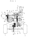
- FIG. 1 is a plane view illustrative of a novel radio controlled engine mechanism to be accommodated in a radio controlled toy car when engine stop in a preferred embodiment according to the present invention.
- FIG. 2 is a plane view illustrative of a novel radio controlled engine mechanism to be accommodated in a radio controlled toy car when the toy car travels in a forward direction in a preferred embodiment according to the present invention.
- FIG. 3 is a plane view illustrative of a novel radio controlled engine mechanism to be accommodated in a radio controlled toy car immediately before a back-motor will be started in a preferred embodiment according to the present invention.
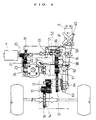
- FIG. 4 is a plane view illustrative of a novel radio controlled engine mechanism to be accommodated in a radio controlled toy car when the toy car travels in a reverse direction in a preferred embodiment according to the present invention.
- FIG. 5 is a front view illustrative of a radio control signal transmitter to be used for sending radio control signals to a radio control toy car.
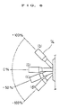
- FIG. 6 is a view illustrative of operations of a radio control signal transmitter to be used for sending radio control signals to a radio control toy car in a preferred embodiment according to the present invention.
- FIG. 7 is a block diagram illustrative of internal circuits in a radio control signal transmitter to be used for sending radio control signals to a radio control toy car in a preferred embodiment according to the present invention.
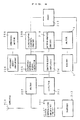
- FIG. 8 is a block diagram illustrative of how to control every elements constituting a novel radio controlled engine mechanism to be accommodated in a radio controlled toy car in a preferred embodiment according to the present invention.
- a preferred embodiment according to the present invention will be described, which provides a novel radio controlled engine mechanism to be accommodated in a radio controlled toy car.
- the novel radio controlled engine mechanism is placed on a chassis and accommodated within a body of a radio controlled toy car. Rear tires 1 and 2 are mechanically connected via a rotary shaft 17 which is placed on the chassis.
- the novel radio controlled engine mechanism has an engine 3 for generating a driving power and transmits the driving power onto an engine rotary shaft.
- the novel radio controlled engine mechanism also has a first transmission system which is provided between the engine 3 and the rotary shaft 17 connected to the rear tires 1 and 2 for transmitting the driving power to the rotary shaft 17. Front tires are not illustrated in FIG. 1.
- the novel radio controlled engine mechanism also has a motor 4 being connected with a rotary shaft and generating a rotation force.
- the novel radio controlled engine mechanism also has a second transmission system 6 provided between the engine 3 and the motor 4 for transmitting the rotation force generated by the motor onto the rotary shaft 10 of the engine 3 in order to start the engine 3.
- the novel radio controlled engine mechanism also has a third transmission system 7 provided between the motor 4 and the first transmission system 5 for transmitting the rotation force generated by the motor 4 to the first transmission system 5 whereby the rotation direction of the rotary shaft 17 connected to the rear tiers 1 and 2 is changed whilst the rotation direction of the rotary shaft 10 of the engine 3 remains unchanged.
- the novel radio controlled engine mechanism also has a servo mechanism 8 connected to both the first and third transmission systems 5 and 7 for controlling the driving power of the engine 3.
- the first transmission system 5 comprises the following elements.
- a first gear 11 is provided, which has a center portion being mechanically connected to the rotary shaft 10 of the engine 3.
- a second gear 12 is provided, which is engaged with the first gear 11 and has a center portion mechanically fixed with a rotary shaft.
- the second gear 12 is larger in diameter than the first gear 11.
- the second gear 12 rotates in an opposite direction to the first gear 11.
- a third gear 13 is provided on the rotary shaft of the second gear 12.
- the third gear 13 is smaller in diameter than the second gear 11.
- the third gear 13 rotates the same direction as the second gear 12.
- a fourth gear 14 is provided, which is engaged with the third gear 13 and has a center portion mechanically fixed with a rotary shaft.
- the fourth gear 14 is slightly larger in diameter than the third gear 13.
- the fourth gear 14 rotates in an opposite direction to the third gear 13.
- a fifth gear 15 is provided on the rotary shaft of the fourth gear 14.
- the fifth gear 15 is slightly smaller in diameter than the fourth gear 14.
- the fifth gear 15 rotates the same direction as the fourth gear 14.
- a sixth gear 16 is provided, which is engaged with the fifth gear 15 and has a center portion mechanically fixed with the rotary shaft 17 of the rear tiers 1 and 2.
- the sixth gear 16 is larger in diameter than the fifth gear 15.
- the sixth gear 16 rotates in an opposite direction to the fifth gear 15 and also opposite to the first gear 11.
- the driving power generated by the engine 3 is therefore transmitted to the rotary shaft 17 connected to the rear tiers 1 and 2 through the above first to sixth gears 11-16.
- the above second transmission system 6 between the motor 4 and the engine 3 comprises the following elements.
- a seventh gear 20 is provided on the rotary shaft of the motor 4.
- An eighth gear 21 is provided, which is engaged with the seventh gear 20 and has a center portion mechanically fixed with a rotary shaft.
- the eighth gear 21 is larger in diameter than the seventh gear 20.
- the eighth gear 21 rotates in an opposite direction to the seventh gear 20 which rotates the same direction as the rotary shaft of the motor 4.
- a ninth gear 22 is provided on the rotary shaft of the eighth gear 21.
- the ninth gear 22 is smaller in diameter than the eighth gear 21. Tthe ninth gear 22 rotates the same direction as the eighth gear 21.
- a tenth gear 23 is provided, which is engaged with the ninth gear 22 and has a center portion mechanically connected with a first one way clutch 24 which has a rotation axis being mechanically fixed with the rotary shaft 10 of the engine 3.
- the tenth gear 23 is larger in diameter than the ninth gear 22.
- the tenth gear 23 rotates in an opposite direction to the ninth gear 22.
- the tenth gear 23 mechanically connected with the first one way clutch 24 rotates in the same direction as the seventh gear 20 or the rotary shaft of the motor 4.
- the first one way clutch 24 is designed to transmit the rotation of the tenth gear 23 to the rotary shaft 10 of the engine 3 but not to transmit the rotation of the rotary shaft 10 of the engine 3 to the tenth gear 23.
- the first one way clutch 24 allows the rotation force generated by the motor 4 to be transmitted to the rotary shaft of the engine 3 but prevents the driving power generated by the engine 3 from being transmitted to the motor 4.
- the third transmission system 7 provided between the motor 4 and the first transmission system 5 comprises the following elements.
- An eleventh gear 31 is provided, which is engaged with the ninth gear 22 of the second transmission system 6.
- the eleventh gear 31 is larger in diameter than the ninth gear 22 and rotates in an opposite direction to the ninth gear 22. Namely, the eleventh gear 31 rotates in the same direction as the seventh gear 20 or the rotary shaft of the motor 4.
- the eleventh gear 31 has a center portion being mechanically fixed with a rotary shaft.
- a universal joint 32 is provided which has a first end being mechanically connected with the rotary shaft connected with the enter portion of the eleventh gear 31. The universal joint 32 rotates in the same direction as the eleventh gear 31.
- a first back shaft 33 is provided, which has a first end being mechanically connected with a second end of the universal joint 32.
- the first back shaft 33 rotates in the same direction as the universal joint 32 or the eleventh gear 31.
- a second back shaft 34 is provided, which has a first end being mechanically connected via a connection pin 35 to a second end of the first back shaft 33.
- the second back shaft 34 is free from the rotation of the first back shaft 33.
- the second back shaft 34 has a second end which is in contact with a spring member 39 sandwiched between a fixed wall and the second end of the second back shaft 34 whereby the second back shaft 34 is pressed by the spring member 39 toward the first back shaft 33.
- the first back shaft 33 is also pressed by the second back shaft 34 toward the universal joint 32.
- the universal joint 32 is also pressed by the first back shaft 33 toward the eleventh gear 31.
- a twelfth gear 36 is provided on the second back shaft 34.
- the twelfth gear 36 has an inner space within which a second one way clutch 37 is accommodated.
- the second one way clutch 37 is in contact directly with the second back shaft 34 and thus the twelfth gear 36 is mechanically connected via the second one way clutch 37 to the second back shaft 34.
- a thirteenth gear 38 is provided, which is engaged not only at its one end with the twelfth gear 36 but also at a diametrically opposite end with the first gear 11 of the first transmission system 5.
- the thirteenth gear 38 is larger in diameter than the twelfth gear 36 and the first gear 11.
- the thirteenth gear 38 rotates in an opposite direction to the first and the thirteenth gears 11 and 38. If the first gear 11 is mechanically connected to the twelfth gear 36 via the thirteenth gear 38, then the first gear 11 rotates in the same direction as the thirteenth gear 38. As described above. the above first and second back shafts 33 and 34 are connected with each other via the connection pin 35 so that the first and second back shafts 33 and 34 may rotate independently from one another.
- the second one way clutch 37 allows the rotation force of the second back shaft 34 to be transmitted to the twelfth gear 36 engaged with the thirteenth gear 38, but prevents the rotation force of the twelfth gear 36 from being transmined to the second back shaft 34. Namely, the second one way clutch 37 is designed to allow the rotation force generated by the motor 4 to be transmitted to first transmission system 5 but prevent the driving power generated by the engine 3 from being transmitted to the motor 4.
- the output of the engine 3 is controllable by the servo mechanism 8.
- the servo mechanism 8 is provided with a servo horn 40 which is cross-shaped to have four arms 40a, 40b, 40c and 40d radial extending from its center portion.
- the end of the first arm 40a of the servo born 40 provided on the servo mechanism 8 is pivatally connected with one end of a first operation shaft 41 which also has an opposite end pivotally connected with a first arm of an L-shaped crank 42 which is pivotally provided in the first transmission system 5 on the chassis of the toy car.
- a second operation shaft 43 is further provided, which has a first end connected with a second arm of the L-shaped crank 42 so that the second operation shaft 43 is mechanically connected to the first operation shaft 41 via the L-shaped crank 42.
- the second operation shaft 43 extends toward the engine 3 so that a second end of the second operation shaft 43 is mechanically connected to the engine 3.
- a third operation shaft 50 is provided, which has a first end mechanically connected with the second arm 40b of the servo born 40.
- a back lever horn 51 is provided, which has a first end being pivotally mounted on the chassis of the toy car.
- a second end of the third operation shaft 50 is mechanically connected with a second end of the back lever horn 51.
- a back lever 52 is fixed on the first back shaft 33.
- a rotary disk 61 is provided, which is mechanically fixed with the rotary shaft of the second gear 12.
- a pair of brake pads 62 is provided, which sandwiches the rotary disk 61.
- the brake pad positioned at outside is provided with a convex portion 63.
- a brake cum 64 is pivotally provided, which has a first end being in contact with the convex portion 63.
- a fourth operation shaft 60 is provided, which has a first end being mechanically connected with the first arm of the L-shaped crank 42 and a second end being mechanically connected with a second end of the brake cum 64.
- the second end of the brake cum 64 is mechanically connected via the fourth operation shaft 60 to the first arm of the L-shaped crank 42 which is further mechanically connected via the first operation shaft 41 to the first arm 40a of the servo horn 40. Consequently, the second end of the brake cum 64 is mechanically connected to the servo horn 40 pivotally provided on the servo mechanism 8.
- the first arm 40a of the servo horn 40 comes distant from the brake pads 62, then the first and fourth operation shafts 41 and 60 move toward the servo horn 40 whereby the first end of the brake cum 64 pushes the convex portion 63 toward the rotary disk 61.
- the brake pads 62 sandwiches the rotary disk 61 to suppress the rotation of the rotary disk 61 fixed on the rotary shaft of the second gear 12.
- a radio control signal transmitter 70 includes a forward/reverse switching section 71, a right-turn/left-turn switching section 71 and a starter switching section having a starter switch button 73.
- the forward/reverse switching section 71 has a forward/reverse switching lever 74 movable in the vertical direction.
- the right-turn/left-turn switching section 71 has a right-turn/left-turn switching lever 75 movable in the horizontal direction.
- the position of the forward/reverse switching lever 74 determines the output of the engine and the forward/reverse traveling direction.
- the internal circuit configurations of the radio control signal transmitter 70 to be used in this preferred embodiment is illustrated in FIG. 7.
- the internal circuit configurations of the radio control signal transmitter 70 are supplied with power by a battery 112.
- the internal circuit configurations of the radio control signal transmitter 70 have a clock pulse oscillator which generates lock pulse signals with a pulse width determined by the level of power supplied by the battery.
- the internal circuit configurations of the radio control signal transmitter 70 have a forward/reverse volume 101 in association with the operation of the forward/reverse switching lever 74.
- the forward/reverse volume 101 supplies forward/reverse control signals, in accordance with which the engine 3 operates and a toy car travels in a certain forward or reverse direction.
- the internal circuit configurations of the radio control signal transmitter 70 have a right-turn/left-turn volume 102 in association with the operation of the right-turn/left-turn switching lever 75.
- the right-turn/left-turn volume 102 supplies right-turn/left-turn signals in accordion with which the toy car will turn right or turn left.
- the internal circuit configurations of the radio control signal transmitter 70 also have an engine starter switching circuit 103 in association with the operation of the starter switch button 73.
- the engine starter switching circuit 103 supplies an engine starting signal in accordance with which the engine 3 will be started.
- a first delay circuit 105 is provided which is electrically connected to the forward/reverse volume 101 and the clock pulse oscillator 104.
- a second delay circuit 106 is provided, which is electrically connected to the right-turn/left-turn volume 102 and the clock pulse oscillator 104 in addition connected to the engine starter switching circuit 103.
- the forward/reverse control pulse signals generated by the forward/reverse volume 101 is delayed by the first delay circuit 105 as well as the right-turn/left-turn control pulse signals generated by the right-turn/left-turn volume 102 is also delayed by the second delay circuit 106.
- the engine starting pulse signal generated by the starting switch circuit 103 is also delayed by the second delay circuit 106.
- An encoder circuit 107 is provided, which is connected to the first and second delay circuits 105 and 106 and the clock pulse oscillation circuit 104 for encoding the forward/reverse control pulse signals and the right-turn/left-turn control pulse signals as well as engine starting pulse signal.
- a radio wave oscillator 108 is provided, which is connected to the encoder 107 for fetching the encoded forward/reverse control signals and the right-turn/left-turn control pulse signals as well as engine starting pulse signal to thereby output the radio control signal.
- a radio wave amplifier 109 is also provided, which is electrically connected to the radio wave oscillator 108 for fetching the radio control signal to amplify the same.
- a filter 110 is provided, which is connected to the radio wave amplifier 109 for fetching the amplified radio control signal from the radio wave amplifier 109 and filtering the same. The filtered radio control signal is transmitted via an antenna 111 from the radio control signal transmitter 70.
- the toy car accommodating the engine mechanism described above is further provided with a control section for controlling the engine mechanism.
- the control section has circuit configurations as illustrated in FIG. 8.
- the control section is supplied with power by a battery 213.
- the control section has an antenna 200 which receives the radio control signals having been transmitted from the radio control signal transmitter 70.
- the control section also has a super heterodyne receiving circuit 201 which is electrically, connected to the antenna 200 for fetching the radio control signals from the antenna 200.
- the control section also has a filter 202 which is electrically connected to the antenna 200 for fetching the radio control signals from the antenna 200 and filtering the same.
- the control section also has a detector 203 which is electrically connected to both the filter 202 and the super heterodyne receiving circuit 201 for fetching the radio control signal from the super heterodyne receiving circuit 201 and the filtered radio control signal from the filter 202 to thereby detect a predetermined signal from the fetch radio control signals.
- the control section also has a steering servo amplifier 204 which is electrically connected to the detector 203 for fetching the detected signal and amplifying the same.
- a steering motor 208 is electrically connected to the steering servo amplifier 204 for fetching the amplified signal and controlling the driving operation of the steering motor 208 which is driven in accordance with the amplified signal.
- the control section also has an engine servo amplifier 206 is provided, which is electrically connected to the detector 203 for fetching the amplified signal and amplifying the same.
- the engine servo amplifier 206 is further electrically connected to the engine 3 for feeding the amplified signal to the servo mechanism 8 illustrated in FIG. 1 so as to drive the servo mechanism 8 and cause the rotation of the servo horn 40, whereby the output of the engine 3 is controlled via the servo mechanism 8 which is under the control in accordance with the amplified signal from the engine servo amplifier 206.
- the control section also has a start/reverse signal detector 205, which is electrically connected to both the steering servo amplifier 204 and the engine servo amplifier 206 for fetching the signal amplified detection signal to detect any start/reverse signal from the fetched signal.
- the control section also has a plug heater control circuit 209 which is electrically connected to the start/reverse signal detector 205 for fetching the detected start/reverse signal from the start/reverse signal detector 205 and also connected to an engine plug 212 of the engine 3 for firing the engine plug 212 in accordance with the start signal fetched from the start/reverse signal detector 205.
- the control section also has a motor driving circuit 210 which is electrically connected to the start/reverse signal detector 205 for fetching the detected start/reverse signal from the start/reverse signal detector 205 and also connected to the motor 4 for driving the same in accordance with the start signal fetched from the start/reverse signal detector 205 whereby the engine 3 is started by the driving force of the motor 4.
- the motor driving circuit 210 also drives the engine 3 in a reverse direction in accordance with the reverse signal fetched from the start/reverse signal detector 205.
- the radio control signal transmitter 70 is operated to have the forward/reverse switching section 71 positioned horizontally as illustrated in FIG. 6 (a).
- the starter switch button 73 illustrated in FIG. 5 is pushed to cause the starter switching circuit 103 driven thereby resulting in no output signal from the right-turn/left-turn volume 102.
- the output signal from the forward/reverse volume 101 is transmitted through the first delay circuit 105, the encoder circuit 107, the radio wave oscillator 108, the radio wave amplifier 109, the filter 110 and the antenna 111 to the antenna of the control section for controlling the engine mechanism.
- the signal is then transmitted to the start/reverse signal detector 205 where the start/reverse signal is detected.
- the detected start/reverse signal is then transmitted into the plug heater control circuit 209.
- the start/reverse signal is transmitted into the motor driving circuit 210.
- the plug is fired by the plug heater control circuit 209 and concurrently the motor 4 causes the rotation of the rotary shaft of the engine 3 whereby the engine 3 starts.
- the engine mechanism operates as follows. At the same time when the plug is fired by the plug heater control circuit 209, the motor 4 commences to rotate whereby the seventh, eighth, ninth and tenth gears 20, 21, 22 and 23 are caused to rotate. This rotation force is transmitted via the first one way clutch 24 to the rotary shaft of the engine whereby the engine 3 starts.
- the servo horn 40 provided on the servo mechanism 8 is positioned as illustrated in FIG. 1 so that only the second back shaft 34 enters into and is engaged with the second one way clutch 37. The rotation of the rotary shaft of the motor 4 is transmitted through the seventh, eighth, ninth and eleventh gears 20, 21, 22 and 31 and the universal joint 32 to the first back shaft 33.
- the radio control signal transmitter 70 is operated to have the forward/reverse switching section 71 positioned upwardly as illustrated in FIG. 6 (b) whereby the forward signal is transmitted from the radio control signal transmitter 70 to the control section of the engine mechanism.
- the forward signal is then transmitted via the detector 203 to the engine servo amplifier 206 before the servo horn 40 on the servo mechanism 8 rotates in a clockwise direction so as to be positioned as illustrated in FIG. 2.
- the first and second cperation shafts 41 and 43 move to have the throttle full open and take the engine 3 to the full power.
- the full driving power of the engine 3 is transmitted through the first transmission system 5 to the rotary shaft of the rear tiers 1 and 2 whereby the toy car travels in the forward direction.
- the servo horn 40 moves the third operation shaft so that the first and second back shafts 33 and 34 move toward the universal joint 32.
- the second back shaft 34 enters into or is engaged with the second one way clutch 37 and the first back shaft 33 is not engaged with the second one way clutch 37.
- the driving power of the engine 3 showing full power is also transmitted through the first gear 11, the thirteenth gear 38, the twelfth gear 36 and the second one way clutch 37 to the second back shaft 34. Since, however, as described above the first back shaft 33 is not engaged with the second one way clutch 37 and the first back shaft 33 is free from the rotation of the second back shaft 34, the driving power of the engine 3 is not transmitted to the first back shaft 33. Namely, the driving power of the engine 3 is not transmitted to the motor 4.
- the radio control signal transmitter 70 is operated to have the forward/reverse switching section 71 positioned downwardly as illustrated in FIG. 6 (c) whereby the reverse signal is transmitted from the radio control signal transmitter 70 to the control section of the engine mechanism.
- the reverse signal is then transmitted to the engine servo amplifier 206 whereby the engine servo amplifier 206 drives the servo horn 40.
- the servo horn 40 rotates in the anticlockwise direction and then comes positioned as illustrated in FIG. 3.
- the first operation shaft 41 moves toward the servo horn 40 and the second operation shaft 43 moves toward the engine 3 thereby the throttle of the engine 3 is closed. As a result, the engine 3 enters into the idling state.
- the fourth operation shaft moves toward the servo horn 40 whereby the brake cum 64 pushes the convex portion 63 of the brake pad 62 so that the paired brake pads 62 sandwich the rotary disk 61 to suppers the rotation of the rotary disk 61 to control the traveling in the forward direction of the toy car.
- the third operation shaft 50 moves toward the servo horn 40 whereby the back level horn 51 rotates to push the back level 52.
- the first and second back shafts 33 and 34 move toward the spring member 39 so that the first back shaft 33 slightly enters into the second one way clutch 37.
- the radio control signal transmitter 70 is operated to have the forward/reverse switching section 71 positioned downwardly as illustrated in FIG. 6 (d) whereby the reverse signal still remains transmitted from the radio control signal transmitter 70 to the control section of the engine mechanism.
- the reverse signal is also transmitted via the engine servo amplifier 206 into the start/reverse signal detector 205.
- the reverse signal is then transmitted to the motor driving circuit 210.
- the servo horn 40 further rotates in the anticlockwise direction.
- the first operation shaft further moves toward the servo horn 40 and the fourth operation shaft 60 also moves toward the servo horn 40 whereby the brake cum 64 further rotates the until the brake cum 64 is detached from the convex portion 63 of the brake pad 62.
- the paired brake pads comes separated from the rotary disk 61 whereby the rotary disk 61 becomes able to freely rotate.
- the third operation shaft moves toward the servo horn 40 whereby the back lever horn 51 further rotates and further pushes the back lever 52 toward the second back shaft 34 so that not only the second back shaft 34 but also the first back shaft 33 sufficiently enter into and are securely engaged with the second one way clutch 37. Since the second operation shaft remains in a position near that illustrated in FIG. 3 where the throttle is closed, the throttle remains closed and thus the engine 3 remains in the idling state.
- the rotation force generated by the motor 4 is transmitted to the first back shaft 33 securely engaged with the second one way clutch 37 whereby the rotation force is then transmitted through the twelfth gear 36 and the thirteenth gear 38 to the first transmission system 5.
- the rotation direction of the motor 4 has been set so that the rotary shaft connected with the rear tires 1 and 2 rotates in an opposite direction to when the driving power of the engine 3 has been transmitted to the rotary shaft connected with the rear tiers 1 and 2. As a result, the toy car travels in the reverse direction.
- the motor 4 states to rotate a predetermined time interval, for example, three minutes after the back signal is inputted into the control section for controlling the engine mechanism so that during the time interval the rotation speed is reduced by the brake pads to thereby present any damage of the gear systems due to rapid change in the rotation direction.
- the motor 4 rotates in the opposite direction to that when the motor 4 causes the engine 3 to start. Since the one way clutch is provided between the rotary shaft of the engine 3 and the motor 4, the rotation force of the motor 4 in the reverse mode is not prevented by the one way clutch from being transmitted to the rotary shaft of the engine 3.
Landscapes
- Engineering & Computer Science (AREA)
- Computer Networks & Wireless Communication (AREA)
- Toys (AREA)
Abstract
Description
- The present invention relates to a radio controlled toy vehicle, and more particularly to a radio controlled engine mechanism provided in a toy vehicle which travels in forward and reverse directions.
- In prior art, it is possible to use not only a motor but also an engine for driving a radio controlled toy vehicle. It can be generally said that engines can provide a larger driving force than motors. The rotation direction of the motor may easily be changed, whilst it is difficult to change in rotation direction of the engine. This means that if the motor is used then it is easy to change the direction of traveling of the toy vehicle by changing the rotation direction of the motor, whilst if the engine is used then it is difficult to change the direction of traveling of the toy vehicle because the engine rotates in one direction.
- The use of engine for driving the toy vehicle renders traveling performance more attractive and more powerful, but raises the following problems.
- First, the engine is normally designed to rotate in one direction, namely is unable to change its rotation direction. This means that if the engine is used, which is designed to rotate in one direction, then it is difficult to change the traveling direction of the vehicle provided with the engine due to impossibility of changing the rotation direction of the engine.
- Second, in prior art, the engine accommodated in the radio controlled toy vehicle is normally started by hand power. This means that every when the engine is started, the user has to start the engine by his or her hand power. Actually, engine stop often appears particularly when the toy vehicle hits the obstacle. In this case, it is necessary to restart the engine by hand power. It is therefore required to develop a novel engine mechanism which may be started under radio control and may change the traveling direction of the vehicle under radio control.
- Accordingly, it is an object of the present invention to provide a novel radio controlled engine mechanism accommodated in a radio controlled toy vehicle, which is free from the problems as described above.
- It is a further object of the present invention to provide a novel radio controlled engine mechanism being accommodated in a radio controlled toy vehicle and being started under radio control.
- It is a further object of the present invention to provide a novel radio controlled engine mechanism being accommodated in a radio controlled toy vehicle and being capable of changing the traveling direction of the radio controlled toy vehicle under radio control.
- The present invention provides an engine driving mechanism provided in a toy vehicle, comprising the following elements. At least an engine is provided to generate a first driving power for an action of a toy vehicle. A first driving power transmission system is provided to be engaged between the engine and a first rotary shaft for transmitting the driving power to the first rotary shaft. At least a motor is provided, which is capable of rotations in first and second directions at a second driving power. A second driving power transmission system is provided to be engaged between the engine and the motor for transmitting the second driving power generated by the motor to the engine. A first gear is provided to be engaged with the second driving power transmission system for a rotation by the second driving power. A universal joint is provided, which has a first end being engaged with a center of the first gear for a rotation around a longitudinal axis thereof in association with the rotation of the first gear. A first shaft is provided, which has a first end being engaged with a second end of the universal joint for a rotation around a longitudinal axis thereof in association with the rotation of the universal joint. A second shaft is provided, which has a first end mechanically connected via a correction pin to a second end of the first shaft for a rotation around a longitudinal axis thereof freely from the rotation of the first shaft. A spring member is provided in contact with a second end of the second shaft for pressing the second shaft toward the first shaft. A first one way clutch is provided, which is capable of engagement with both the first and second shafts. A rotation force transmission system is provided, which is engaged between the first clutch and the first driving power transmission system. A servo mechanism is provided, which has a servo horn being capable of rotations around a center hereof in first and second directions. A first arm is provided, which has a first end being pivotaly engaged with the servo horn at a first point apart from the center of the servo horn and a second end connected with a first lever being capable of pushing the first shaft toward the second shaft. If the first arm moves toward the servo horn by a rotation of the servo horn, then not only the second shaft but also the first shaft enter into and are engaged with the first clutch whereby the second driving power of the motor is transmitted to the first driving power transmission system. If, however, the first arm moves toward the first shaft, then only the second shaft enters into and is engaged with the first clutch whilst the first shaft is not engaged with the first clutch whereby the second driving power of the motor is transmitted to the first shaft but not transmitted to the first driving power transmission system. A second arm is provided, which has a first end being pivotaly engaged with the servo horn at a second point apart from the center of the servo horn and a second end connected with a second lever. A third arm is provided, which has a first end being pivotaly engaged with the second lever and a second end connected with a throttle of the engine. If the servo horn rotates to have the first arm move toward the servo horn, then the third arm moves toward the second lever whereby the throttle is closed to place the engine in idling state. If the servo horn rotates to have the first arm move toward the second lever, then the third arm moves toward the engine whereby the throttle is opened to place the engine in power state.
- The second driving power transmission system may have a one-way clutch which transmits the second driving power of the motor into the engine when the motor rotates a rotary shaft of the engine in the forward direction, but prevent a transmission of the second driving power to the engine when the motor rotates a rotary shaft of the engine in the reverse direction.
- The first driving power transmission system may comprise a first gear mechanism engaged with the engine and provided with a rotary disk which rotates in association with rotations of gears constituting the first gear mechanism, a second gear mechanism engaged with the first gear mechanism, a pair of brake pads sandwiching the rotary disk, a cum pivotally provided to push one of the brake pads toward an counterpart thereof, and a fourth arm being pivotally connected between the cum and the second lever which is connected with the second end of the first arm so that if the third arm moves toward the engine to close the throttle, then the cum pushes the brake pad whereby the rotary disk is sandwiched to suppress a rotation of the rotary disk.
- A preferred embodiment according to the present invention will be described in detail with reference to the accompanying drawings.
- FIG. 1 is a plane view illustrative of a novel radio controlled engine mechanism to be accommodated in a radio controlled toy car when engine stop in a preferred embodiment according to the present invention.
- FIG. 2 is a plane view illustrative of a novel radio controlled engine mechanism to be accommodated in a radio controlled toy car when the toy car travels in a forward direction in a preferred embodiment according to the present invention.
- FIG. 3 is a plane view illustrative of a novel radio controlled engine mechanism to be accommodated in a radio controlled toy car immediately before a back-motor will be started in a preferred embodiment according to the present invention.
- FIG. 4 is a plane view illustrative of a novel radio controlled engine mechanism to be accommodated in a radio controlled toy car when the toy car travels in a reverse direction in a preferred embodiment according to the present invention.
- FIG. 5 is a front view illustrative of a radio control signal transmitter to be used for sending radio control signals to a radio control toy car.
- FIG. 6 is a view illustrative of operations of a radio control signal transmitter to be used for sending radio control signals to a radio control toy car in a preferred embodiment according to the present invention.
- FIG. 7 is a block diagram illustrative of internal circuits in a radio control signal transmitter to be used for sending radio control signals to a radio control toy car in a preferred embodiment according to the present invention.
- FIG. 8 is a block diagram illustrative of how to control every elements constituting a novel radio controlled engine mechanism to be accommodated in a radio controlled toy car in a preferred embodiment according to the present invention.
- A preferred embodiment according to the present invention will be described, which provides a novel radio controlled engine mechanism to be accommodated in a radio controlled toy car.
- The novel radio controlled engine mechanism is placed on a chassis and accommodated within a body of a radio controlled toy car.
Rear tires rotary shaft 17 which is placed on the chassis. The novel radio controlled engine mechanism has anengine 3 for generating a driving power and transmits the driving power onto an engine rotary shaft. The novel radio controlled engine mechanism also has a first transmission system which is provided between theengine 3 and therotary shaft 17 connected to therear tires rotary shaft 17. Front tires are not illustrated in FIG. 1. The novel radio controlled engine mechanism also has amotor 4 being connected with a rotary shaft and generating a rotation force. The novel radio controlled engine mechanism also has asecond transmission system 6 provided between theengine 3 and themotor 4 for transmitting the rotation force generated by the motor onto the rotary shaft 10 of theengine 3 in order to start theengine 3. The novel radio controlled engine mechanism also has athird transmission system 7 provided between themotor 4 and thefirst transmission system 5 for transmitting the rotation force generated by themotor 4 to thefirst transmission system 5 whereby the rotation direction of therotary shaft 17 connected to therear tiers engine 3 remains unchanged. The novel radio controlled engine mechanism also has aservo mechanism 8 connected to both the first andthird transmission systems engine 3. - The
first transmission system 5 comprises the following elements. Afirst gear 11 is provided, which has a center portion being mechanically connected to the rotary shaft 10 of theengine 3. Asecond gear 12 is provided, which is engaged with thefirst gear 11 and has a center portion mechanically fixed with a rotary shaft. Thesecond gear 12 is larger in diameter than thefirst gear 11. Thesecond gear 12 rotates in an opposite direction to thefirst gear 11. Athird gear 13 is provided on the rotary shaft of thesecond gear 12. Thethird gear 13 is smaller in diameter than thesecond gear 11. Thethird gear 13 rotates the same direction as thesecond gear 12. Afourth gear 14 is provided, which is engaged with thethird gear 13 and has a center portion mechanically fixed with a rotary shaft. Thefourth gear 14 is slightly larger in diameter than thethird gear 13. Thefourth gear 14 rotates in an opposite direction to thethird gear 13. Afifth gear 15 is provided on the rotary shaft of thefourth gear 14. Thefifth gear 15 is slightly smaller in diameter than thefourth gear 14. Thefifth gear 15 rotates the same direction as thefourth gear 14. Asixth gear 16 is provided, which is engaged with thefifth gear 15 and has a center portion mechanically fixed with therotary shaft 17 of therear tiers sixth gear 16 is larger in diameter than thefifth gear 15. Thesixth gear 16 rotates in an opposite direction to thefifth gear 15 and also opposite to thefirst gear 11. The driving power generated by theengine 3 is therefore transmitted to therotary shaft 17 connected to therear tiers - The above
second transmission system 6 between themotor 4 and theengine 3 comprises the following elements. Aseventh gear 20 is provided on the rotary shaft of themotor 4. Aneighth gear 21 is provided, which is engaged with theseventh gear 20 and has a center portion mechanically fixed with a rotary shaft. Theeighth gear 21 is larger in diameter than theseventh gear 20. Theeighth gear 21 rotates in an opposite direction to theseventh gear 20 which rotates the same direction as the rotary shaft of themotor 4. Aninth gear 22 is provided on the rotary shaft of theeighth gear 21. Theninth gear 22 is smaller in diameter than theeighth gear 21. Ttheninth gear 22 rotates the same direction as theeighth gear 21. Atenth gear 23 is provided, which is engaged with theninth gear 22 and has a center portion mechanically connected with a first one way clutch 24 which has a rotation axis being mechanically fixed with the rotary shaft 10 of theengine 3. Thetenth gear 23 is larger in diameter than theninth gear 22. Thetenth gear 23 rotates in an opposite direction to theninth gear 22. Namely, thetenth gear 23 mechanically connected with the first one way clutch 24 rotates in the same direction as theseventh gear 20 or the rotary shaft of themotor 4. The first one way clutch 24 is designed to transmit the rotation of thetenth gear 23 to the rotary shaft 10 of theengine 3 but not to transmit the rotation of the rotary shaft 10 of theengine 3 to thetenth gear 23. Namely, the first one way clutch 24 allows the rotation force generated by themotor 4 to be transmitted to the rotary shaft of theengine 3 but prevents the driving power generated by theengine 3 from being transmitted to themotor 4. - The
third transmission system 7 provided between themotor 4 and thefirst transmission system 5 comprises the following elements. Aneleventh gear 31 is provided, which is engaged with theninth gear 22 of thesecond transmission system 6. Theeleventh gear 31 is larger in diameter than theninth gear 22 and rotates in an opposite direction to theninth gear 22. Namely, theeleventh gear 31 rotates in the same direction as theseventh gear 20 or the rotary shaft of themotor 4. Theeleventh gear 31 has a center portion being mechanically fixed with a rotary shaft. Auniversal joint 32 is provided which has a first end being mechanically connected with the rotary shaft connected with the enter portion of theeleventh gear 31. Theuniversal joint 32 rotates in the same direction as theeleventh gear 31. Afirst back shaft 33 is provided, which has a first end being mechanically connected with a second end of theuniversal joint 32. Thefirst back shaft 33 rotates in the same direction as the universal joint 32 or theeleventh gear 31. Asecond back shaft 34 is provided, which has a first end being mechanically connected via a connection pin 35 to a second end of thefirst back shaft 33. Thesecond back shaft 34 is free from the rotation of thefirst back shaft 33. Thesecond back shaft 34 has a second end which is in contact with aspring member 39 sandwiched between a fixed wall and the second end of thesecond back shaft 34 whereby thesecond back shaft 34 is pressed by thespring member 39 toward thefirst back shaft 33. As a result, thefirst back shaft 33 is also pressed by thesecond back shaft 34 toward theuniversal joint 32. Theuniversal joint 32 is also pressed by thefirst back shaft 33 toward theeleventh gear 31. Atwelfth gear 36 is provided on thesecond back shaft 34. Thetwelfth gear 36 has an inner space within which a second one way clutch 37 is accommodated. The second one way clutch 37 is in contact directly with thesecond back shaft 34 and thus thetwelfth gear 36 is mechanically connected via the second one way clutch 37 to thesecond back shaft 34. Athirteenth gear 38 is provided, which is engaged not only at its one end with thetwelfth gear 36 but also at a diametrically opposite end with thefirst gear 11 of thefirst transmission system 5. Thethirteenth gear 38 is larger in diameter than thetwelfth gear 36 and thefirst gear 11. Thethirteenth gear 38 rotates in an opposite direction to the first and thethirteenth gears first gear 11 is mechanically connected to thetwelfth gear 36 via thethirteenth gear 38, then thefirst gear 11 rotates in the same direction as thethirteenth gear 38. As described above. the above first andsecond back shafts second back shafts second back shaft 34 to be transmitted to thetwelfth gear 36 engaged with thethirteenth gear 38, but prevents the rotation force of thetwelfth gear 36 from being transmined to thesecond back shaft 34. Namely, the second one way clutch 37 is designed to allow the rotation force generated by themotor 4 to be transmitted tofirst transmission system 5 but prevent the driving power generated by theengine 3 from being transmitted to themotor 4. - The output of the
engine 3 is controllable by theservo mechanism 8. Theservo mechanism 8 is provided with aservo horn 40 which is cross-shaped to have fourarms first arm 40a of the servo born 40 provided on theservo mechanism 8 is pivatally connected with one end of afirst operation shaft 41 which also has an opposite end pivotally connected with a first arm of an L-shapedcrank 42 which is pivotally provided in thefirst transmission system 5 on the chassis of the toy car. Asecond operation shaft 43 is further provided, which has a first end connected with a second arm of the L-shapedcrank 42 so that thesecond operation shaft 43 is mechanically connected to thefirst operation shaft 41 via the L-shapedcrank 42. Thesecond operation shaft 43 extends toward theengine 3 so that a second end of thesecond operation shaft 43 is mechanically connected to theengine 3. When theservo mechanism 8 is driven to cause a rotation of theservo horn 40 whereby thefirst operation shaft 41 almost reciprocally moves. This movement of the first operations haft 41 causes the rotation of the L-shapedcrank 42 whereby thesecond operation shaft 43 almost reciprocally moves to cause alternating operations of opening and closing a slot of theengine 3. Since the degree in opening of the slot of theengine 3 substantially determines an amount of fuel injection from a carburetor 3a, the revolution speed of theengine 3 varies to depend upon the degree in opening of the slot of theengine 3. Further, athird operation shaft 50 is provided, which has a first end mechanically connected with thesecond arm 40b of the servo born 40. In thethird transmission system 7, aback lever horn 51 is provided, which has a first end being pivotally mounted on the chassis of the toy car. A second end of thethird operation shaft 50 is mechanically connected with a second end of theback lever horn 51. Aback lever 52 is fixed on thefirst back shaft 33. When theservo mechanism 8 is driven and theservo horn 40 rotates so that thethird operation shaft 50 shows almost reciprocal motion whereby the second end of theback lever horn 51 moves almost along the longitudinal direction of thefirst back shaft 33. If thethird operation shaft 50 moves toward theservo horn 40, then the second end of theback lever horn 51 presses theback lever 52 fixed on thefirst back shaft 33. As a result, the first andsecond back shafts spring member 39 so that the not only thesecond back shaft 34 but also thefirst back shaft 33 come engaged with the second oneway clutch 37. The engagement of thefirst back shaft 33 with the second one way clutch 37 causes the rotation force of thefirst back shaft 33 to be transmitted via thetwelfth gear 36 and thethirteenth gear 38 to thefirst transmission system 5. - Moreover, in the
first transmission system 5, arotary disk 61 is provided, which is mechanically fixed with the rotary shaft of thesecond gear 12. A pair ofbrake pads 62 is provided, which sandwiches therotary disk 61. The brake pad positioned at outside is provided with aconvex portion 63. Abrake cum 64 is pivotally provided, which has a first end being in contact with theconvex portion 63. Afourth operation shaft 60 is provided, which has a first end being mechanically connected with the first arm of the L-shapedcrank 42 and a second end being mechanically connected with a second end of thebrake cum 64. Thus, the second end of thebrake cum 64 is mechanically connected via thefourth operation shaft 60 to the first arm of the L-shapedcrank 42 which is further mechanically connected via thefirst operation shaft 41 to thefirst arm 40a of theservo horn 40. Consequently, the second end of thebrake cum 64 is mechanically connected to theservo horn 40 pivotally provided on theservo mechanism 8. When thefirst arm 40a of theservo horn 40 comes distant from thebrake pads 62, then the first andfourth operation shafts servo horn 40 whereby the first end of thebrake cum 64 pushes theconvex portion 63 toward therotary disk 61. As a result, thebrake pads 62 sandwiches therotary disk 61 to suppress the rotation of therotary disk 61 fixed on the rotary shaft of thesecond gear 12. - With reference to FIG. 5, a radio
control signal transmitter 70 includes a forward/reverse switching section 71, a right-turn/left-turn switching section 71 and a starter switching section having astarter switch button 73. The forward/reverse switching section 71 has a forward/reverse switching lever 74 movable in the vertical direction. The right-turn/left-turn switching section 71 has a right-turn/left-turn switching lever 75 movable in the horizontal direction. - With reference to FIG. 6, the position of the forward/
reverse switching lever 74 determines the output of the engine and the forward/reverse traveling direction. - Internal circuit configurations of the radio
control signal transmitter 70 to be used in this preferred embodiment is illustrated in FIG. 7. The internal circuit configurations of the radiocontrol signal transmitter 70 are supplied with power by abattery 112. The internal circuit configurations of the radiocontrol signal transmitter 70 have a clock pulse oscillator which generates lock pulse signals with a pulse width determined by the level of power supplied by the battery. The internal circuit configurations of the radiocontrol signal transmitter 70 have a forward/reverse volume 101 in association with the operation of the forward/reverse switching lever 74. The forward/reverse volume 101 supplies forward/reverse control signals, in accordance with which theengine 3 operates and a toy car travels in a certain forward or reverse direction. The internal circuit configurations of the radiocontrol signal transmitter 70 have a right-turn/left-turn volume 102 in association with the operation of the right-turn/left-turn switching lever 75. The right-turn/left-turn volume 102 supplies right-turn/left-turn signals in accordion with which the toy car will turn right or turn left. The internal circuit configurations of the radiocontrol signal transmitter 70 also have an enginestarter switching circuit 103 in association with the operation of thestarter switch button 73. The enginestarter switching circuit 103 supplies an engine starting signal in accordance with which theengine 3 will be started. Afirst delay circuit 105 is provided which is electrically connected to the forward/reverse volume 101 and theclock pulse oscillator 104. Asecond delay circuit 106 is provided, which is electrically connected to the right-turn/left-turn volume 102 and theclock pulse oscillator 104 in addition connected to the enginestarter switching circuit 103. The forward/reverse control pulse signals generated by the forward/reverse volume 101 is delayed by thefirst delay circuit 105 as well as the right-turn/left-turn control pulse signals generated by the right-turn/left-turn volume 102 is also delayed by thesecond delay circuit 106. The engine starting pulse signal generated by the startingswitch circuit 103 is also delayed by thesecond delay circuit 106. Anencoder circuit 107 is provided, which is connected to the first andsecond delay circuits pulse oscillation circuit 104 for encoding the forward/reverse control pulse signals and the right-turn/left-turn control pulse signals as well as engine starting pulse signal. Aradio wave oscillator 108 is provided, which is connected to theencoder 107 for fetching the encoded forward/reverse control signals and the right-turn/left-turn control pulse signals as well as engine starting pulse signal to thereby output the radio control signal. Aradio wave amplifier 109 is also provided, which is electrically connected to theradio wave oscillator 108 for fetching the radio control signal to amplify the same. Afilter 110 is provided, which is connected to theradio wave amplifier 109 for fetching the amplified radio control signal from theradio wave amplifier 109 and filtering the same. The filtered radio control signal is transmitted via an antenna 111 from the radiocontrol signal transmitter 70. - The toy car accommodating the engine mechanism described above is further provided with a control section for controlling the engine mechanism. The control section has circuit configurations as illustrated in FIG. 8. The control section is supplied with power by a
battery 213. The control section has anantenna 200 which receives the radio control signals having been transmitted from the radiocontrol signal transmitter 70. The control section also has a superheterodyne receiving circuit 201 which is electrically, connected to theantenna 200 for fetching the radio control signals from theantenna 200. The control section also has afilter 202 which is electrically connected to theantenna 200 for fetching the radio control signals from theantenna 200 and filtering the same. The control section also has adetector 203 which is electrically connected to both thefilter 202 and the superheterodyne receiving circuit 201 for fetching the radio control signal from the superheterodyne receiving circuit 201 and the filtered radio control signal from thefilter 202 to thereby detect a predetermined signal from the fetch radio control signals. The control section also has asteering servo amplifier 204 which is electrically connected to thedetector 203 for fetching the detected signal and amplifying the same. Asteering motor 208 is electrically connected to thesteering servo amplifier 204 for fetching the amplified signal and controlling the driving operation of thesteering motor 208 which is driven in accordance with the amplified signal. The control section also has anengine servo amplifier 206 is provided, which is electrically connected to thedetector 203 for fetching the amplified signal and amplifying the same. Theengine servo amplifier 206 is further electrically connected to theengine 3 for feeding the amplified signal to theservo mechanism 8 illustrated in FIG. 1 so as to drive theservo mechanism 8 and cause the rotation of theservo horn 40, whereby the output of theengine 3 is controlled via theservo mechanism 8 which is under the control in accordance with the amplified signal from theengine servo amplifier 206. The control section also has a start/reverse signal detector 205, which is electrically connected to both thesteering servo amplifier 204 and theengine servo amplifier 206 for fetching the signal amplified detection signal to detect any start/reverse signal from the fetched signal. The control section also has a plugheater control circuit 209 which is electrically connected to the start/reverse signal detector 205 for fetching the detected start/reverse signal from the start/reverse signal detector 205 and also connected to anengine plug 212 of theengine 3 for firing theengine plug 212 in accordance with the start signal fetched from the start/reverse signal detector 205. The control section also has amotor driving circuit 210 which is electrically connected to the start/reverse signal detector 205 for fetching the detected start/reverse signal from the start/reverse signal detector 205 and also connected to themotor 4 for driving the same in accordance with the start signal fetched from the start/reverse signal detector 205 whereby theengine 3 is started by the driving force of themotor 4. Themotor driving circuit 210 also drives theengine 3 in a reverse direction in accordance with the reverse signal fetched from the start/reverse signal detector 205. - The following descriptions will focus on the operations of the above engine mechanism radio-controllable.
- In order to start the
engine 3, the radiocontrol signal transmitter 70 is operated to have the forward/reverse switching section 71 positioned horizontally as illustrated in FIG. 6 (a). In the meantime, thestarter switch button 73 illustrated in FIG. 5 is pushed to cause thestarter switching circuit 103 driven thereby resulting in no output signal from the right-turn/left-turn volume 102. As a result, only the output signal from the forward/reverse volume 101 is transmitted through thefirst delay circuit 105, theencoder circuit 107, theradio wave oscillator 108, theradio wave amplifier 109, thefilter 110 and the antenna 111 to the antenna of the control section for controlling the engine mechanism. The signal is then transmitted to the start/reverse signal detector 205 where the start/reverse signal is detected. - The detected start/reverse signal is then transmitted into the plug
heater control circuit 209. In the meantime, the start/reverse signal is transmitted into themotor driving circuit 210. As a result, the plug is fired by the plugheater control circuit 209 and concurrently themotor 4 causes the rotation of the rotary shaft of theengine 3 whereby theengine 3 starts. - In starting the
engine 3, the engine mechanism operates as follows. At the same time when the plug is fired by the plugheater control circuit 209, themotor 4 commences to rotate whereby the seventh, eighth, ninth andtenth gears engine 3 starts. On the other hand, in thethird transmission system 7, theservo horn 40 provided on theservo mechanism 8 is positioned as illustrated in FIG. 1 so that only thesecond back shaft 34 enters into and is engaged with the second oneway clutch 37. The rotation of the rotary shaft of themotor 4 is transmitted through the seventh, eighth, ninth andeleventh gears first back shaft 33. Since, however, thesecond back shaft 34 is free from the rotation of thefirst back shaft 33 and as described above the first back shaft is not engaged with the second one way clutch 37, the rotation force having transmitted from themotor 4 is not transmitted to the second oneway clutch 37. As a result, the rotation force having been transmitted from themotor 4 is not transmitted to thefirst transmission system 5 and therear tiers rear tiers - After the
engine 3 has started, the radiocontrol signal transmitter 70 is operated to have the forward/reverse switching section 71 positioned upwardly as illustrated in FIG. 6 (b) whereby the forward signal is transmitted from the radiocontrol signal transmitter 70 to the control section of the engine mechanism. The forward signal is then transmitted via thedetector 203 to theengine servo amplifier 206 before theservo horn 40 on theservo mechanism 8 rotates in a clockwise direction so as to be positioned as illustrated in FIG. 2. The first andsecond cperation shafts engine 3 to the full power. The full driving power of theengine 3 is transmitted through thefirst transmission system 5 to the rotary shaft of therear tiers servo horn 40 moves the third operation shaft so that the first andsecond back shafts universal joint 32. As a result, only thesecond back shaft 34 enters into or is engaged with the second one way clutch 37 and thefirst back shaft 33 is not engaged with the second oneway clutch 37. The driving power of theengine 3 showing full power is also transmitted through thefirst gear 11, thethirteenth gear 38, thetwelfth gear 36 and the second one way clutch 37 to thesecond back shaft 34. Since, however, as described above thefirst back shaft 33 is not engaged with the second one way clutch 37 and thefirst back shaft 33 is free from the rotation of thesecond back shaft 34, the driving power of theengine 3 is not transmitted to thefirst back shaft 33. Namely, the driving power of theengine 3 is not transmitted to themotor 4. - If it is required to have the toy car travel in the reverse direction, the radio
control signal transmitter 70 is operated to have the forward/reverse switching section 71 positioned downwardly as illustrated in FIG. 6 (c) whereby the reverse signal is transmitted from the radiocontrol signal transmitter 70 to the control section of the engine mechanism. The reverse signal is then transmitted to theengine servo amplifier 206 whereby theengine servo amplifier 206 drives theservo horn 40. Theservo horn 40 rotates in the anticlockwise direction and then comes positioned as illustrated in FIG. 3. Thefirst operation shaft 41 moves toward theservo horn 40 and thesecond operation shaft 43 moves toward theengine 3 thereby the throttle of theengine 3 is closed. As a result, theengine 3 enters into the idling state. On the other hand, the fourth operation shaft moves toward theservo horn 40 whereby thebrake cum 64 pushes theconvex portion 63 of thebrake pad 62 so that the pairedbrake pads 62 sandwich therotary disk 61 to suppers the rotation of therotary disk 61 to control the traveling in the forward direction of the toy car. Further, thethird operation shaft 50 moves toward theservo horn 40 whereby theback level horn 51 rotates to push theback level 52. As a result, the first andsecond back shafts spring member 39 so that thefirst back shaft 33 slightly enters into the second oneway clutch 37. - Subsequently, the radio
control signal transmitter 70 is operated to have the forward/reverse switching section 71 positioned downwardly as illustrated in FIG. 6 (d) whereby the reverse signal still remains transmitted from the radiocontrol signal transmitter 70 to the control section of the engine mechanism. The reverse signal is also transmitted via theengine servo amplifier 206 into the start/reverse signal detector 205. The reverse signal is then transmitted to themotor driving circuit 210. Theservo horn 40 further rotates in the anticlockwise direction. The first operation shaft further moves toward theservo horn 40 and thefourth operation shaft 60 also moves toward theservo horn 40 whereby thebrake cum 64 further rotates the until thebrake cum 64 is detached from theconvex portion 63 of thebrake pad 62. The paired brake pads comes separated from therotary disk 61 whereby therotary disk 61 becomes able to freely rotate. Further, the third operation shaft moves toward theservo horn 40 whereby theback lever horn 51 further rotates and further pushes theback lever 52 toward thesecond back shaft 34 so that not only thesecond back shaft 34 but also thefirst back shaft 33 sufficiently enter into and are securely engaged with the second oneway clutch 37. Since the second operation shaft remains in a position near that illustrated in FIG. 3 where the throttle is closed, the throttle remains closed and thus theengine 3 remains in the idling state. On the other hand, the rotation force generated by themotor 4 is transmitted to thefirst back shaft 33 securely engaged with the second one way clutch 37 whereby the rotation force is then transmitted through thetwelfth gear 36 and thethirteenth gear 38 to thefirst transmission system 5. The rotation direction of themotor 4 has been set so that the rotary shaft connected with therear tires engine 3 has been transmitted to the rotary shaft connected with therear tiers - The
motor 4 states to rotate a predetermined time interval, for example, three minutes after the back signal is inputted into the control section for controlling the engine mechanism so that during the time interval the rotation speed is reduced by the brake pads to thereby present any damage of the gear systems due to rapid change in the rotation direction. - When the toy car travels in the reverse direction, the
motor 4 rotates in the opposite direction to that when themotor 4 causes theengine 3 to start. Since the one way clutch is provided between the rotary shaft of theengine 3 and themotor 4, the rotation force of themotor 4 in the reverse mode is not prevented by the one way clutch from being transmitted to the rotary shaft of theengine 3. - Needless to say, the above described novel radio-controllable engine mechanism is applicable to any other toys.
- Whereas any modifications of the present invention will be apparent to a person having ordinary skill in the art, to which the invention pertains, it is to be understood that embodiments as shown and described by way of illustrations are by no means intended to be considered in a limiting sense. Accordingly, it is to be intended to cover by claims all modifications which fall within the spirit and scope of the present invention.
Claims (3)
- An engine driving mechanism provided in a toy vehicle, comprising:at least an engine generating a first driving power for an action of a toy vehicle;a first driving power transmission system engaged between said engine and a first rotary shaft for transmitting said driving power to said first rotary shaft ;at least a motor being capable of rotations in first and second directions at a second driving power ;a second driving power transmission system engaged between said engine and said motor for transmitting said second driving power generated by said motor to said engine ; anda first gear engaged with said second driving power transmission system for a rotation by said second driving power,characterized in that said engine driving mechanism further comprises :a universal joint having a first end being engaged with a center of said first gear for a rotation around a longitudinal axis thereof in association with said rotation of said first gear ;a first shaft having a first end being engaged with a second end of said universal joint for a rotation around a longitudinal axis thereof in association with said rotation of said universal joint ;a second shaft having a first end mechanically connected via a connection pin to a second end of said first shaft for a rotation around a longitudinal axis thereof freely from said rotation of said first shaft ;a pressing means being in contact with a second end of said second shaft for pressing said second shaft toward said first shaft ;a first one way clutch being capable of engagement with both said first and second shafts ;a rotation force transmission system being engaged between said first clutch and said first driving power transmission system ;a servo mechanism having a servo horn being capable of rotations around a center hereof in first and second directions ;a first arm having a first end being pivotaly engaged with said servo horn at a first point apart from said center of said servo horn and a second end connected with a first lever being capable of pushing said first shaft toward said second shaft so that if said first arm moves toward said servo horn by a rotation of said servo horn, then not only said second shaft but also said first shaft enter into and are engaged with said first clutch whereby said second driving power of said motor is transmitted to said first driving power transmission system, and if said first arm moves toward said first shaft, then only said second shaft enters into and is engaged with said first clutch whilst said first shaft is not engaged with said first clutch whereby said second driving power of said motor is transmitted to said first shaft but not transmitted to said first driving power transmission system ;a second arm having a first end being pivotaly engaged with said servo horn at a second point apart from said center of said servo horn and a second end connected with a second lever ; anda third arm having a first end being pivotaly engaged with said second lever and a second end connected with a throttle of said engine so that if said servo horn rotates to have said first arm move toward said servo horn, then said third arm moves toward said second lever whereby said throttle is closed to place said engine in idling state, and if said servo horn rotates to have said first arm move toward said second lever, then said third arm moves toward said engine whereby said throttle is opened to place said engine in power state.
- The engine driving mechanism as claimed in claim 1, characterized in that said second driving power transmission system has a one-way clutch which transmits said second driving power of said motor into said engine when said motor rotates a rotary shaft of said engine in said forward direction, but prevent a transmission of said second driving power to said engine when said motor rotates a rotary shaft of said engine in said reverse direction.
- The engine driving mechanism as claimed in claim 1, characterized in that said first driving power transmission system comprises :a first gear mechanism engaged with said engine and provided with a rotary disk which rotates in association with rotations of gears constituting said first gear mechanism ;a second gear mechanism engaged with said first gear mechanism ;a pair of brake pads sandwiching said rotary disk ;a cum pivotally provided to push one of said brake pads toward an counterpart thereof ; anda fourth arm being pivotally connected between said cum and said second lever which is connected with said second end of said first arm so that if said third arm moves toward said engine to close said throttle, then said cum pushes said brake pad whereby said rotary disk is sandwiched to suppress a rotation of said rotary disk.
Applications Claiming Priority (3)
| Application Number | Priority Date | Filing Date | Title |
|---|---|---|---|
| JP14771195 | 1995-06-14 | ||
| JP14771195A JP3759199B2 (en) | 1995-06-14 | 1995-06-14 | Drive mechanism of radio controlled toy |
| JP147711/95 | 1995-06-14 |
Publications (3)
| Publication Number | Publication Date |
|---|---|
| EP0748642A2 true EP0748642A2 (en) | 1996-12-18 |
| EP0748642A3 EP0748642A3 (en) | 1997-01-29 |
| EP0748642B1 EP0748642B1 (en) | 2001-05-09 |
Family
ID=15436488
Family Applications (1)
| Application Number | Title | Priority Date | Filing Date |
|---|---|---|---|
| EP96304449A Expired - Lifetime EP0748642B1 (en) | 1995-06-14 | 1996-06-14 | Radio controlled engine mechanism provided in a toy vehicle |
Country Status (5)
| Country | Link |
|---|---|
| US (1) | US5762532A (en) |
| EP (1) | EP0748642B1 (en) |
| JP (1) | JP3759199B2 (en) |
| DE (1) | DE69612696T2 (en) |
| NO (1) | NO962552L (en) |
Cited By (1)
| Publication number | Priority date | Publication date | Assignee | Title |
|---|---|---|---|---|
| WO2015085335A3 (en) * | 2013-12-12 | 2015-09-11 | Peter Jakobs | Method and device for starting single-cylinder engines |
Families Citing this family (12)
| Publication number | Priority date | Publication date | Assignee | Title |
|---|---|---|---|---|
| US20060068903A1 (en) * | 1996-12-30 | 2006-03-30 | Walker Jay S | Methods and apparatus for facilitating accelerated play of a flat rate play gaming session |
| ATA169098A (en) | 1998-10-09 | 2000-04-15 | Eisenbeiss Soehne Maschinen Un | GEARBOX FOR DRIVING THE SCREWS OF A TWIN-SCREW EXTRUDER |
| US6386058B1 (en) * | 2000-09-12 | 2002-05-14 | Ke-Way Lu | Forward/backward steering control mechanism for a remote-controlled toy car |
| US7222684B2 (en) * | 2001-02-12 | 2007-05-29 | Innovation First, Inc. | System, apparatus, and method for providing control of a toy vehicle |
| WO2002076564A1 (en) * | 2001-03-22 | 2002-10-03 | Nikko Co., Ltd | Drive controller |
| US20030162597A1 (en) * | 2002-02-27 | 2003-08-28 | Tek Nek Toys International, Inc. | Interactive playset |
| US6732602B2 (en) | 2002-09-06 | 2004-05-11 | Ke-Way Lu | Dual-gearshift forward backward control mechanism for remote control toy car |
| US7559822B2 (en) * | 2003-04-28 | 2009-07-14 | Traxxas Lp | Electronic shift lockout for scale model vehicle |
| WO2005077127A2 (en) * | 2004-02-11 | 2005-08-25 | Mattel, Inc. | Remote-controlled toy vehicle having multi-mode drive mechanism |
| US7581624B2 (en) * | 2005-04-07 | 2009-09-01 | Traxxas Lp | Braking pad caliper apparatus for a model vehicle |
| US7900753B2 (en) * | 2007-08-02 | 2011-03-08 | Golden Lion Enterprise Co., Ltd. | Braking ratio device for a remote control model car |
| KR101230930B1 (en) * | 2010-12-24 | 2013-02-07 | 주식회사 로보스타 | Driving apparatus for robot |
Citations (1)
| Publication number | Priority date | Publication date | Assignee | Title |
|---|---|---|---|---|
| GB2050180A (en) * | 1979-04-24 | 1981-01-07 | Mabuchi Motor Co | Model toy |
Family Cites Families (7)
| Publication number | Priority date | Publication date | Assignee | Title |
|---|---|---|---|---|
| US2679712A (en) * | 1948-09-07 | 1954-06-01 | Structo Mfg Company | Remotely controlled vehicle |
| US3314189A (en) * | 1964-08-10 | 1967-04-18 | William P Carroll | Remote, light actuated control means for models |
| US3386406A (en) * | 1965-12-14 | 1968-06-04 | Ichiro Tsunoda | Control apparatus of an electrically driven toy |
| US3553886A (en) * | 1968-04-03 | 1971-01-12 | Harry M Hamilton | Clutch and drive assembly for model vehicles |
| US3705387A (en) * | 1971-01-11 | 1972-12-05 | Kenneth Stern | Remote control system for electro-mechanical vehicle |
| US3683546A (en) * | 1971-11-01 | 1972-08-15 | Jerobee Ind Inc | Control system for remotely controlled model car |
| US4301617A (en) * | 1978-08-30 | 1981-11-24 | Shaw Christopher W | Model steam locomotives |
-
1995
- 1995-06-14 JP JP14771195A patent/JP3759199B2/en not_active Expired - Fee Related
-
1996
- 1996-06-14 DE DE69612696T patent/DE69612696T2/en not_active Expired - Fee Related
- 1996-06-14 EP EP96304449A patent/EP0748642B1/en not_active Expired - Lifetime
- 1996-06-14 NO NO962552A patent/NO962552L/en unknown
- 1996-06-14 US US08/663,715 patent/US5762532A/en not_active Expired - Fee Related
Patent Citations (1)
| Publication number | Priority date | Publication date | Assignee | Title |
|---|---|---|---|---|
| GB2050180A (en) * | 1979-04-24 | 1981-01-07 | Mabuchi Motor Co | Model toy |
Cited By (1)
| Publication number | Priority date | Publication date | Assignee | Title |
|---|---|---|---|---|
| WO2015085335A3 (en) * | 2013-12-12 | 2015-09-11 | Peter Jakobs | Method and device for starting single-cylinder engines |
Also Published As
| Publication number | Publication date |
|---|---|
| EP0748642A3 (en) | 1997-01-29 |
| US5762532A (en) | 1998-06-09 |
| JP3759199B2 (en) | 2006-03-22 |
| NO962552L (en) | 1996-12-16 |
| JPH08336673A (en) | 1996-12-24 |
| EP0748642B1 (en) | 2001-05-09 |
| DE69612696T2 (en) | 2002-01-31 |
| NO962552D0 (en) | 1996-06-14 |
| DE69612696D1 (en) | 2001-06-13 |
Similar Documents
| Publication | Publication Date | Title |
|---|---|---|
| US5762532A (en) | Radio controlled engine mechanism provided in a toy vehicle | |
| JPS6245756Y2 (en) | ||
| WO2007009745A3 (en) | Control button comprising integrated functionality | |
| JP3631803B2 (en) | Radio controlled toy missile launcher | |
| EP3088263A1 (en) | Pedal control device, particularly for a motor-vehicle | |
| US4976650A (en) | Device for starting a toy | |
| CH636565A5 (en) | Device for remotely actuating mechanical, electrical and electromechanical members, appliances and accessory devices installed on a motor vehicle | |
| US20030236121A1 (en) | Electronic shift lockout for scale model vehicle | |
| EP0750929B1 (en) | Radio controlled toy car with an improved steering system | |
| JPH08175330A (en) | Vehicular ignition key device | |
| EP0700703A2 (en) | Vehicle toy mounting projectile launching mechanism | |
| JP2886239B2 (en) | Automatic shifting operation device | |
| JP2778200B2 (en) | Starter switch | |
| KR100394590B1 (en) | Drive mechanism of starting system for automobile | |
| JPS59217038A (en) | Speed change control device | |
| JP2002129789A (en) | Motor device | |
| JPH0241935A (en) | Steering operating structure for agricultural work vehicle | |
| JPH0118219Y2 (en) | ||
| JPH04194329A (en) | Throttle valve controller for internal combustion engine | |
| JPH0110261Y2 (en) | ||
| JPH02181071A (en) | Kick starting device for motor bicycle | |
| JPS6234312Y2 (en) | ||
| JPS6212679Y2 (en) | ||
| US6122146A (en) | Autostop mechanism for tape driving apparatus | |
| JPH10304515A (en) | Device for accelerating electric vehicle |
Legal Events
| Date | Code | Title | Description |
|---|---|---|---|
| PUAI | Public reference made under article 153(3) epc to a published international application that has entered the european phase |
Free format text: ORIGINAL CODE: 0009012 |
|
| PUAL | Search report despatched |
Free format text: ORIGINAL CODE: 0009013 |
|
| AK | Designated contracting states |
Kind code of ref document: A2 Designated state(s): BE CH DE ES FR GB IT LI NL |
|
| AK | Designated contracting states |
Kind code of ref document: A3 Designated state(s): BE CH DE ES FR GB IT LI NL |
|
| 17P | Request for examination filed |
Effective date: 19970411 |
|
| 17Q | First examination report despatched |
Effective date: 19981222 |
|
| GRAG | Despatch of communication of intention to grant |
Free format text: ORIGINAL CODE: EPIDOS AGRA |
|
| GRAG | Despatch of communication of intention to grant |
Free format text: ORIGINAL CODE: EPIDOS AGRA |
|
| GRAH | Despatch of communication of intention to grant a patent |
Free format text: ORIGINAL CODE: EPIDOS IGRA |
|
| GRAH | Despatch of communication of intention to grant a patent |
Free format text: ORIGINAL CODE: EPIDOS IGRA |
|
| GRAA | (expected) grant |
Free format text: ORIGINAL CODE: 0009210 |
|
| AK | Designated contracting states |
Kind code of ref document: B1 Designated state(s): BE CH DE ES FR GB IT LI NL |
|
| PG25 | Lapsed in a contracting state [announced via postgrant information from national office to epo] |
Ref country code: LI Free format text: LAPSE BECAUSE OF FAILURE TO SUBMIT A TRANSLATION OF THE DESCRIPTION OR TO PAY THE FEE WITHIN THE PRESCRIBED TIME-LIMIT Effective date: 20010509 Ref country code: IT Free format text: LAPSE BECAUSE OF FAILURE TO SUBMIT A TRANSLATION OF THE DESCRIPTION OR TO PAY THE FEE WITHIN THE PRE;WARNING: LAPSES OF ITALIAN PATENTS WITH EFFECTIVE DATE BEFORE 2007 MAY HAVE OCCURRED AT ANY TIME BEFORE 2007. THE CORRECT EFFECTIVE DATE MAY BE DIFFERENT FROM THE ONE RECORDED.SCRIBED TIME-LIMIT Effective date: 20010509 Ref country code: CH Free format text: LAPSE BECAUSE OF FAILURE TO SUBMIT A TRANSLATION OF THE DESCRIPTION OR TO PAY THE FEE WITHIN THE PRESCRIBED TIME-LIMIT Effective date: 20010509 Ref country code: BE Free format text: LAPSE BECAUSE OF FAILURE TO SUBMIT A TRANSLATION OF THE DESCRIPTION OR TO PAY THE FEE WITHIN THE PRESCRIBED TIME-LIMIT Effective date: 20010509 |
|
| REG | Reference to a national code |
Ref country code: CH Ref legal event code: EP |
|
| REF | Corresponds to: |
Ref document number: 69612696 Country of ref document: DE Date of ref document: 20010613 |
|
| ET | Fr: translation filed | ||
| REG | Reference to a national code |
Ref country code: CH Ref legal event code: PL |
|
| PG25 | Lapsed in a contracting state [announced via postgrant information from national office to epo] |
Ref country code: ES Free format text: LAPSE BECAUSE OF FAILURE TO SUBMIT A TRANSLATION OF THE DESCRIPTION OR TO PAY THE FEE WITHIN THE PRESCRIBED TIME-LIMIT Effective date: 20011130 |
|
| REG | Reference to a national code |
Ref country code: GB Ref legal event code: IF02 |
|
| PLBE | No opposition filed within time limit |
Free format text: ORIGINAL CODE: 0009261 |
|
| STAA | Information on the status of an ep patent application or granted ep patent |
Free format text: STATUS: NO OPPOSITION FILED WITHIN TIME LIMIT |
|
| 26N | No opposition filed | ||
| REG | Reference to a national code |
Ref country code: GB Ref legal event code: 732E |
|
| NLS | Nl: assignments of ep-patents |
Owner name: NIKKO CO., LTD. Effective date: 20080408 |
|
| REG | Reference to a national code |
Ref country code: FR Ref legal event code: TP |
|
| PGFP | Annual fee paid to national office [announced via postgrant information from national office to epo] |
Ref country code: NL Payment date: 20090615 Year of fee payment: 14 |
|
| PGFP | Annual fee paid to national office [announced via postgrant information from national office to epo] |
Ref country code: GB Payment date: 20090610 Year of fee payment: 14 Ref country code: DE Payment date: 20090615 Year of fee payment: 14 |
|
| REG | Reference to a national code |
Ref country code: NL Ref legal event code: V1 Effective date: 20110101 |
|
| GBPC | Gb: european patent ceased through non-payment of renewal fee |
Effective date: 20100614 |
|
| REG | Reference to a national code |
Ref country code: FR Ref legal event code: ST Effective date: 20110228 |
|
| PG25 | Lapsed in a contracting state [announced via postgrant information from national office to epo] |
Ref country code: DE Free format text: LAPSE BECAUSE OF NON-PAYMENT OF DUE FEES Effective date: 20110101 |
|
| PG25 | Lapsed in a contracting state [announced via postgrant information from national office to epo] |
Ref country code: FR Free format text: LAPSE BECAUSE OF NON-PAYMENT OF DUE FEES Effective date: 20100630 Ref country code: NL Free format text: LAPSE BECAUSE OF NON-PAYMENT OF DUE FEES Effective date: 20110101 |
|
| PG25 | Lapsed in a contracting state [announced via postgrant information from national office to epo] |
Ref country code: GB Free format text: LAPSE BECAUSE OF NON-PAYMENT OF DUE FEES Effective date: 20100614 |
|
| PGFP | Annual fee paid to national office [announced via postgrant information from national office to epo] |
Ref country code: FR Payment date: 20090611 Year of fee payment: 14 |