EP0747892A2 - Improved optical disc tracking control - Google Patents
Improved optical disc tracking control Download PDFInfo
- Publication number
- EP0747892A2 EP0747892A2 EP96301868A EP96301868A EP0747892A2 EP 0747892 A2 EP0747892 A2 EP 0747892A2 EP 96301868 A EP96301868 A EP 96301868A EP 96301868 A EP96301868 A EP 96301868A EP 0747892 A2 EP0747892 A2 EP 0747892A2
- Authority
- EP
- European Patent Office
- Prior art keywords
- signal
- optical disc
- light beam
- tracking
- control
- Prior art date
- Legal status (The legal status is an assumption and is not a legal conclusion. Google has not performed a legal analysis and makes no representation as to the accuracy of the status listed.)
- Granted
Links
Images


Classifications
-
- G—PHYSICS
- G11—INFORMATION STORAGE
- G11B—INFORMATION STORAGE BASED ON RELATIVE MOVEMENT BETWEEN RECORD CARRIER AND TRANSDUCER
- G11B7/00—Recording or reproducing by optical means, e.g. recording using a thermal beam of optical radiation by modifying optical properties or the physical structure, reproducing using an optical beam at lower power by sensing optical properties; Record carriers therefor
- G11B7/08—Disposition or mounting of heads or light sources relatively to record carriers
- G11B7/085—Disposition or mounting of heads or light sources relatively to record carriers with provision for moving the light beam into, or out of, its operative position or across tracks, otherwise than during the transducing operation, e.g. for adjustment or preliminary positioning or track change or selection
- G11B7/08505—Methods for track change, selection or preliminary positioning by moving the head
- G11B7/08517—Methods for track change, selection or preliminary positioning by moving the head with tracking pull-in only
-
- G—PHYSICS
- G11—INFORMATION STORAGE
- G11B—INFORMATION STORAGE BASED ON RELATIVE MOVEMENT BETWEEN RECORD CARRIER AND TRANSDUCER
- G11B7/00—Recording or reproducing by optical means, e.g. recording using a thermal beam of optical radiation by modifying optical properties or the physical structure, reproducing using an optical beam at lower power by sensing optical properties; Record carriers therefor
- G11B7/08—Disposition or mounting of heads or light sources relatively to record carriers
- G11B7/09—Disposition or mounting of heads or light sources relatively to record carriers with provision for moving the light beam or focus plane for the purpose of maintaining alignment of the light beam relative to the record carrier during transducing operation, e.g. to compensate for surface irregularities of the latter or for track following
- G11B7/0943—Methods and circuits for performing mathematical operations on individual detector segment outputs
Landscapes
- Optical Recording Or Reproduction (AREA)
- Moving Of The Head For Recording And Reproducing By Optical Means (AREA)
- Moving Of Head For Track Selection And Changing (AREA)
- Supporting Of Heads In Record-Carrier Devices (AREA)
- Holo Graphy (AREA)
- Electrochromic Elements, Electrophoresis, Or Variable Reflection Or Absorption Elements (AREA)
- Optical Head (AREA)
- Moving Of The Head To Find And Align With The Track (AREA)
Abstract
Description
- This invention generally relates to an improved method and apparatus for optical disc tracking control in an optical disc storage device. Particularly, the present invention relates to radially moving a light beam that is tracking an information track on an optical disc to another information track on the optical disc in a controlled fashion while the storage device tracking servo loop is in a closed mode of operation.
- An optical disc storage device can be either a device or system that is capable of retrieving information stored by an optical disc, or a device or system that is capable of both recording information to and retrieving information from an optical disc. Examples of optical disc storage devices that are capable of retrieving information from an optical disc include compact disc (CD) players, video laser disc (L) players and compact disc read-only-memory (CD-Rom) drives. Examples of optical disc storage devices that are capable of both recording information to an optical disc and retrieving information from an optical disc include recordable mini-disc (MD) players, magneto-optical (MO) disc drives and compact disc recordable (CD-R) drives.
- Information is generally stored by an optical disc in the form of concentric or spiral tracks sometimes referred to as information tracks. In the case where information is already stored by an optical disc, the information tracks contain regions of optical contrast that represent the stored information. In the case of an unrecorded or blank optical disc containing per-formatted tracks for recording information, a track that will become an information track may or may not have regions of optical contrast. The area located between two information tracks on an optical disc is sometimes referred to as a non-information track.
- When an optical storage device is in its normal mode of operation, i.e. retrieving information from or recording information to an optical disc, the storage device rotates the disc while using a light beam to retrieve information from or record information to the disc. As the optical disc rotates, the light beam radially traverses the disc. While the light beam traverses the optical disc, a tracking servo loop in the optical disc storage device keeps the beam of light centered on the information track, or the track that will become the information track in the case of recording information to a disc.
- An optical disc tracking servo is a closed loop system that allows a light beam to remain centered on an optical disc information track during normal operation of an optical disc storage device. The tracking servo readjusts the radial position of the light beam by sensing when the light beam drifts off the center of the information track. The tracking servo senses when the light beam is not centered on an information track by measuring the intensity of light reflected by the surface of the optical disc.
- Generally, the intensity of light reflected by the surface of an optical disc is the least when it is reflected by the center of an information track. Using this principle, a tracking servo generally senses the intensity of light reflected at one or both edges of an information track to detect when a light beam is drifting off center and to determine in which direction the light beam is drifting. Therefore, a tracking servo system that is in a closed loop mode of operation senses when the light beam floats off the center of the information track by detecting changes in the intensity of light reflected at one or both edges of an information track and moves the beam back into a position where the intensity of reflected light is optimal for center tracking.
- In the case where a tracking servo measures the intensity of light reflected at both edges of an information track, the intensity of reflected light that is optimal for center tracking occurs when the intensity of light reflected at both edges of an information track is the same. The same principle holds true for both one and three beam optical disc storage devices. In the case where a tracking servo measures the intensity of light reflected at one edge of an information track, the intensity of reflected light that is optimal for center tracking is based on some calibrated value. The latter method is less favored due to difficulties associated with calibrating an appropriate centering value.
- Optical disc storage devices are generally capable of performing various special operations to assist in positioning the light beam on the optical disc. These special functions are generally outside of the normal mode of operation of the storage device and include such operations as PAUSE, or still mode, and SEARCH, or seek mode. A PAUSE operation causes the light beam of a storage device to jump to an adjacent information track on the optical disc so that the most recently processed information is processed again by the storage device. A PAUSE operation gives the appearance of suspending normal operation of the storage device. The duration that operation of the storage device appears to be suspended depends on how many successive PAUSE operations are initiated such that the same information is repeatedly processed.
- During a SEARCH operation, the optical storage device typically searches for a specific target track address on an optical disc. Achieving a search operation may require the light beam to radially cross several information tracks before the target address is found. Once the target address is found, the optical disc storage device can return to its normal mode of retrieving or recording information.
- An optical disc storage devices typically performs a PAUSE or SEARCH operation, by disengaging the tracking servo loop for some period of time during the PAUSE or SEARCH operation. When the tracking servo loop is disengaged it is no longer closed and is referred to as being in an open loop mode, or simply that the loop is open. The tracking servo loop is disengaged (or open) during a PAUSE or SEARCH operation to allow the beam to freely move between information tracks. Keeping the tracking servo loop engaged (or closed) while attempting to move the beam between information tracks during a PAUSE or SEARCH operation would frustrate such attempted operations, because the tracking servo system would attempt to keep the beam centered on the information track. Therefore, optical storage devices generally keep the tracking servo loop open during some portion of a PAUSE or SEARCH operation.
- As alluded to above, sending an overriding signal to a tracking servo to radially move a light beam across an optical disc while the tracking servo loop is closed would result in an inefficient or frustrated PAUSE or SEARCH operation. While more efficient than the latter, opening and closing a tracking servo loop while performing a PAUSE or SEARCH operation has a disadvantage of using up time that could otherwise be used by the optical disc storage device during its normal operating mode of retrieving or recording information.
- One attempt to improve the efficiency of a seek operation proposes moving an optical head radially across a disc according to the characteristics of a seek profile signal that is supplied to the track positioning component of a tracking servo system independently from data read off the disc. Periodically sampled differences between the actual head position and the independently supplied seek profile signal are used to drive the track positioning component of the tracking servo system to adjust the head position so that the desired seek profile is maintained. Examples of seek operations that propose using an independently supplied seek profile signal and sampling can be seen in U.S. Pat. Nos. 4,980,876 and 5,210,726.
- A disadvantage of the above proposed seek method, however, is that time is still expended sampling and adjusting differences between the actual head position and the independently supplied seek profile signal. Another disadvantage is that the above proposed seek method is susceptible to unpredicted noise and transients between sampling.
- The invention is defined in the accompanying independent claims. Preferred features are recited in the dependent claims.
- The present invention allows the light beam of an optical disc storage device to radially move between different information tracks of an optical disc while the storage device tracking servo loop remains in a substantially continuous closed loop mode of operation. The invention operates to radially move a light beam from one information track to another during a closed loop mode of operation by activating two control signals introduced into the closed tracking servo loop to create a phantom track center that radially moves across the optical disc. Because the tracking servo loop is in a closed loop mode of operation, the tracking servo operates to keep the light beam centered on the point that the tracking servo considers to be the center of an information track; in this case the phantom track center. Therefore, the tracking servo causes the light beam to radially move across the disc in a closed loop mode of operation by keeping the light beam centered on the moving phantom track center.
- The phantom track center is created by multiplying the two activated control signals with two tracking servo loop feedback signals to produce two modified feedback signals. The phantom track center radially moves across the disc by independently varying the voltages of the two control signals in a predefined manner. The two modified feedback signals are compared to each other with an operational amplifier to generate an error signal that is supplied to the track positioning component of the closed tracking servo loop. The error signal has the effect of attempting to cause the tracking servo to position the light beam over the phantom track center while at the same time moving the phantom track center, thus causing the light beam to radially move across the optical disc.
- The feedback signals are the same signals that provide information about the position of a light beam relative to the center of an information track during normal closed loop tracking. However, when the control signals are activated, the feedback signals provide information about the position of the light beam relative to the phantom track center as the phantom track center radially moves across the optical disc. The position of the light beam relative to the phantom track center is supplied by the feedback signals and multiplied with the control signals to produce the two modified feedback signals, thus completing the loop. The process is continuously repeated thereby creating a closed tracking servo loop that radially moves a beam of light from one information track to another.
- The present invention can be put into practice in various ways some of which will now be described with reference to the accompanying drawings in which :
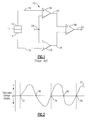
- FIG. 1 is a partial circuit diagram of a conventional tracking error detection apparatus for use in an optical disc storage device.
- FIG. 2 is an example of a tracking error signal when a light beam radially moves across an optical disc when the tracking servo loop is an open mode of operation.
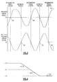
- FIG. 3 depicts the tracking error signal in FIG. 2 and an inverted tracking error signal of FIG. 2.
- FIG. 4 is a voltage signal curve that linearly varies voltage between +1 volt and -1 volt.
- FIG. 5 is a plot of two component signals that make up a tracking error signal when subtracted from each other.
- FIG. 6 is an example of staggered control signals that when multiplied by the component signals of a tracking error signal cause a light beam to radially move across a disc while the tracking servo is in a closed loop mode of operation.
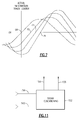
- FIG. 7 is a conceptual illustration of how a phantom track center moves across an optical disc.
- FIG. 8 is an example of staggered control signals that when multiplied by the component signals of a tracking error signal cause a light beam to radially move across a disc while the tracking servo is in a closed loop mode of operation.
- FIG. 9 is an example of staggered control signals that when multiplied by the component signals of a tracking error signal cause a light beam to radially move across a disc in a direction that is opposite of the direction the light beam moves using the control signals in FIG. 8.
- FIG. 10 is a circuit diagram of an embodiment of the present invention.
- FIG. 11 is an alternative control signal generator.
- The following fundament principles underlying the present invention are provided to assist the reader in gaining a full appreciation for the invention.
- Referring to FIG. 1, there is shown a partial circuit diagram for a conventional tracking
error detection apparatus 10. Trackingerror detection apparatus 10 employs aphoto detector unit 11.Photo detector unit 11 comprises two components, a first photo detector component 12a, and a second photo detector component 12b.Photo detector unit 11 performs the operation of measuring the intensity of light reflected by an optical disc. When an optical disc storage device tracks an information track in a closed loop tracking mode, first photo detector component 12a measures the intensity of light reflected at or near one of the edges of the information track being followed. Second photo detector component 12b measures the intensity of light reflected at or near the other edge of the information track being followed. First photo detector component 12a transmits an electrical signal on asignal 14 that is representative of the intensity of the reflected light measured by photo detector 12a. Second photo detector component 12b transmits an electrical signal on asignal 16 that is representative of the intensity of the reflected light measured by photo detector 12b. -
Signal 14 is coupled to the positive pole ofoperational amplifier 18.Operational amplifier 18 amplifies and transmitssignal 14 as asignal 22.Signal 16 is coupled to the positive pole ofoperational amplifier 20.Operational amplifier 20 amplifies and transmitssignal 16 assignal 24.Signal 26 is a voltage common mode (VCM) signal that is coupled to the negative poles ofoperational amplifiers Signal 22 is coupled to the positive pole of difference-summingamplifier 28 andsignal 24 is coupled to the negative pole of difference-summingamplifier 28. Difference-summingamplifier 28 operates as a comparator and generates atracking error signal 30 that represents voltage level differences betweensignals - When a light beam is perfectly centered on an information track in an optical disc storage device using tracking
error detection apparatus 10, the intensity of reflected light measured by first photo detector component 12a is equal to the intensity of reflected light measured by second photo detector component 12b. Consequently, the voltage levels ofsignal amplifier 28 generates trackingerror signal 30 with a voltage level that represents a nominal light beam position on the center of an information track. The voltage level that represents nominal light beam positioning in most tracking servo systems is approximately zero volts. When the light beam starts to drift off the center of the information track being followed, the intensity of reflected light measured by first photo detector component 12a and second photo detector component 12b is different. Consequently, the voltage levels ofsignal amplifier 28 generates atracking error signal 30 that has a voltage level either greater than zero or less than zero, depending on the direction the light beam has drifted off the center of the information track. With this principle in mind, it can be appreciated that difference-summingamplifier 28 generates trackingerror signal 30 with a voltage signal response similar to trackingerror signal 31 shown in FIG. 2, as a light beam radially moves across an optical disc with a tracking servo in open loop mode. - Referring to FIG. 2, there is shown a plot of a
tracking error signal 31, where the horizontal axis represents the radial position of a light beam on an optical disc, and the vertical axis is a voltage level that is representative of the distance the light beam is from either the center of an information track or the center of a non-information track. For example, the light beam is on the center of an information track atpoints points - Referring to FIG. 3, there is shown a
tracking error signal 42 and an invertedtracking error signal 44.Tracking error signal 42 is identical to trackingerror signal 31 shown in FIG. 2.Points error signal 42 represent when the light beam is on the center of an information track. It should be observed that the light beam is on an information track when the positive slope of the sinusoidal tracking error signal crosses the horizontal axis. Alternatively, the light beam is located on the center of a non-information track, i.e., exactly between information tracks, when the negative slope of the sinusoidal tracking error signal crosses the horizontal axis. - It is well recognized that a sinusoidal signal can be inverted by multiplying it by a negative one. It can be observed that inverted
tracking error signal 44, therefore, represents an inversion of trackingerror signal 42. It should also be observed that the positive sinusoidal slope of the inverted track signal crosses the horizontal axis atpoints Points tracking error signal 44, however, indicate that the light beam is centered on the non-information track. Therefore, it should be observed that multiplying the tracking error signal by a negative one moves a point that would ordinarily represent the center of an information track to a point that represents the center of a non-information track. Consequently, inverting a tracking error signal has the ultimate effect of positioning a light beam on a point that it believes the center of an information track, i.e., an apparent information track center or a phantom track center. This is a basic underlying principle upon which the present invention operates. - Referring to FIG. 4, there is shown a
voltage signal curve 54 that linearly varies. voltage between +1 volt and -1 volt. It should be apparent that multiplyingtracking error signal 42 withvoltage signal curve 54, as its voltage level varies from +1 volts to -1 volts, generates inverted trackingerror signal 44. Applying this principle in practice, however, presents two problems that prevent using this method to cause a light beam to radially move across an optical disc while the tracking servo loop is closed. The first problem occurs whenvoltage signal curve 54 reaches approximately 0 volts. Generally, tracking servos become non-operational and lose control when the tracking error signal, or gain, falls within a certain voltage range; typically around zero volts, plus or minus some differential. - The second problem associated with inverting a tracking error signal is that continuous unidirectional radial movement of the light beam across the disc while the tracking servo loop is closed cannot be assured. Recall that inverting a tracking error signal while the tracking loop is closed has the effect of moving an apparent center of an information disc to the center of an adjacent non-information track. However, once the tracking error signal is inverted, the light beam is on the negative slope of the sinusoidal tracking error signal, causing the light beam to think that it is on the center of a non-information track. A light beam on the center of a non-information track is unstable and can move in either direction because it does not know which adjacent information track it should try to center itself over. Therefore, the principle of inverting a tracking error signal by multiplying it by -1 volt to move an apparent information track center on an optical disc serves merely to illustrate one of the principles underlying the operation of the present invention.
- To solve the problems associated with inverting a tracking error signal as described above, the present invention applies the same signal inverting principle described above to cause a phase shift in the component signals that make up the tracking error signal. That is, the present invention inverts signals 22 and 24, shown in FIG. 1. Still referring to FIG. 1, it can be recalled that the difference-summing
amp 28 uses signals 22 and 24 to generate trackingerror signal 30. Referring now to FIG. 5, there is shown a typical sample plot ofsignals Signals signals signal 58 fromsignal 56 produces a tracking error signal similar to trackingerror signal 31 shown in FIG. 2. - Referring to FIG. 6, there are shown two voltage control signals 60 and 62. Control signals 60 and 62 can be used to invert
signals signals signal 22 bysignal 60, and by multiplyingsignal 24 bysignal 62. Control signals 60 and 62 invert signals 22 and 24 in a manner that the tracking servo never senses a gain value that would cause the tracking servo to become non-operational. Again, it will be recalled that a gain value of approximately zero volts, plus or minus some differential, renders a tracking servo non-operational. One method of ensuring that the tracking servo never senses a gain value of approximately 0 volts is by never allowing both control signals 60 and 62 to have a voltage level of 0 volts at the same time. This can be achieved by slightly staggering the time points when each signal starts to change its voltage between +1 volt and -1 volt. The staggered time points referred to are depicted atpoints 61 and 63. - In FIG. 6, it can be observed that
control signal 60 varies its voltage from +1 volt to +0.5 volts ascontrol signal 62 maintains a value of +1 volt.Control signal 60 varies its voltage from +0.5 volts to 0 volts ascontrol signal 62 varies its voltage from +1 volt to +0.5 volts.Control signal 60 varies its voltage from 0 volts to -0.5 volts ascontrol signal 62 varies its voltage from +0.5 volts to 0 volts.Control signal 60 varies it voltage from -0.5 volts to minus -1 volt ascontrol signal 62 varies its voltage from 0 volts to -0.5 volts.Control signal 60 varies its voltage from -1 volt to -0.5 volts ascontrol signal 62 varies its voltage from -0.5 volts to -1 volt.Control signal 60 varies its voltage from -0.5 volts to 0 volts ascontrol signal 62 varies its voltage from -1 volt to -0.5 volts.Control signal 60 varies its voltage from 0 volts to +0.5 volts ascontrol signal 62 varies its voltage from -0.5 volts to 0 volts.Control signal 60 varies its voltage from +0.5 volts to +1 volt ascontrol signal 62 varies its voltage from 0 volts to +0.5 volts.Control signal 60 remains at +1 volt ascontrol signal 62 varies its voltage from +0.5 volts to +1 volt. - It can be seen that at no time do control signals 60 and 62 both have a voltage of approximately 0 volts. This ensures that the tracking servo does not sense a gain value of approximately 0 volts while radially moving a light beam across an optical disc while the tracking servo loop is closed. Therefore, control signals 60 and 62 represent one possible configuration of control signals that can be used to invert
signals -
Staggering starting points 61 and 63 of control signals 60 and 62 also serves to maintain continuous unidirectional movement of the light beam as it radially moves across an optical disc when the tracking servo loop is closed. It should be recognized that both control signals 60 and 62 have a constant voltage level of +1 volt prior totime point 61 oncontrol signal 60. It should also be recognized that multiplyingcontrol signals quantity 1 is an identity function. Therefore, it can be recognized that control signals 60 and 62 are inactive prior totime point 61 when respectively multiplied withsignals signals signals -
Control signal 60, becomes active just aftertime point 61 when control signal 60 starts to change its voltage from +1 volt to -1 volt.Control signal 62, becomes active just after time point 63 when control signal 62 starts to change its voltage from +1 volt to -1 volt. Essentially, a closed loop tracking operation of radially moving a light beam across an optical disc becomes activated when either of the twocontrol signals time point 61. - When a closed loop tracking operation for radially moving a light beam across an optical disc is activated by control signals similar to control
signals signals signals control signals error signal 30, shown in FIG. 1. The induced phase shift has the effect of radially moving the phantom track center across an optical disc. Because the tracking servo loop is closed, the tracking servo attempts to keep the light beam aligned on the phantom track center, thereby causing the light beam to radially move across the optical disc. - Referring to FIG. 7, there is shown a conceptual illustration of a tracking error signal at different points in time while control signals similar to control
signals Point 68 depicts the actual center of an information track.Points - The staggered configuration of control signals 60 and 62, shown in FIG. 6, also causes a phantom track center, and consequently the light beam, to become aligned with the actual center of the next information track when control signals 60 and 62 both return to +1 volt and the closed tracking loop radial move operation becomes inactive. The phantom track center becomes aligned on the center of the next information track when control signals 60 and 62 both return to +1 volt for two reasons. First, it can be recalled that inverting a tracking error signal, i.e., multiplying a tracking error signal by -1, aligns the phantom track center with the center of an adjacent non-information track. The same principle holds true when control signals 60 and 62 are multiplied by the signal responses of
signals - The second reason the phantom track center becomes aligned on the center of the next information track when control signals 60 and 62 both return to +1 volt is as follows. It will be remembered that the staggered nature of control signals 60 and 62 induces a continuous phase shift of the tracking error signal that causes the phantom track center to radially move across an optical disc. The same principle holds true when control signals 60 and 62 change their voltages from -1 volt to +1 volt, because control signals 60 and 62 remain staggered in the same fashion as when they changed their voltages from +1 volt to -1 volt. In other words, the phantom track center continues to move in the same direction when control signals 60 and 62 change their voltages from -1 volt to +1 volt. Additionally, the time it takes control signals 60 and 62 to change from +1 volt to -1 volt is the same time it takes control signals 60 and 62 to change from -1 volt to +1 volt. Therefore, when the phantom track center reaches the center of the adjacent non-information track, it continues to move in the same direction that it was moving when it arrived at the center of the non-information track, and it travels the same distance that it took to reach the center of the non-information track, thus aligning it with the center of the next information track. Consequently, the light beam is positioned on the next information track.
- Therefore, it can be appreciated that activating one complete cycle of control signals 60 and 62 causes the light beam to move one information track. Consequently, the number of tracks that the light beam crosses is determined by the number of control signal cycles produced. One complete active cycle of control signals 60 and 62 is depicted by
time points point 61 onsignal 60, and the time the last control signal returns to +1 volt, i.e.,point 67 onsignal 62. It can also be appreciated that a closed tracking loop operation of radially moving the light beam across an optical disc begins when control signals, similar tocontrol signals signals - The direction that the light beam radially moves across an optical disc during a closed tracking loop radial move operation is dictated by which of the two control signals is the first to commence changing its voltage level from +1 volt to -1 volt. For example, in FIG. 6,
control signal 62 would need to start changing its voltage from +1 volt to -1 volt beforetime point 61 to move the light beam in the opposite direction that the depicted configuration of control signals 60 and 62 would move the light beam. - Linearly changing the voltage of
signals points points - Referring to Fig. 8, there is shown an example of two
control signals signals control signals - Referring to Fig. 9, there is shown control signals 80 and 82. Control signals 80 and 82 depict a control signal configuration that has the effect of radially moving the light beam in the opposite direction that the configuration of control signals 76 and 78, depicted in FIG. 8, radially moves the light beam.
- Referring to FIG. 10, there is shown a schematic diagram of an embodiment of an optical disc
tracking control device 84. In optical disctracking control device 84, there is aphotodiode array 86 that has two components, afirst photodiode component 88, and asecond photodiode component 90.Photodiode array 86 measures the intensity of light reflected by an optical disc. When a light beam is on the center of an information track,first photodiode component 88 measures the intensity of light reflected at or near one of the edges of the tracked information track, andsecond photodiode component 90 measures the intensity of light reflected at or near the other edge of the tracked information track. -
First photodiode component 88 transmits an electrical signal on afirst signal 92 that is representative of the intensity of the reflected light measured byphoto detector 88.Second photodiode component 90 transmits an electrical signal on asecond signal 94 that is representative of the intensity of the reflected light measured byphoto detector 90. -
First signal 92 is amplified by a first per-amplifier 96 and coupled to the positive pole of afirst difference amplifier 98.Second signal 94 is amplified by a second per-amplifier 100 and coupled to the positive pole of asecond difference amplifier 102.VCM signal 108 is a voltage common mode signal that is coupled to the negative poles offirst difference amplifier 98 andsecond difference amplifier 102.VCM signal 108 may be fixed or it may be variable if derived from a reflectivity signal. -
First difference amplifier 98 measures the difference betweenfirst signal 92 and VCM signal 108 and transmits a representative voltage level onfirst feedback signal 104.Second difference amplifier 102 measures the difference betweensecond signal 94 and VCM signal 108 and transmits a voltage level onsecond feedback signal 106. -
Control signal generator 110 has afirst control signal 112 and asecond control signal 114. Control signal generator also has adirectional control signal 116 and amove control signal 118.First feedback signal 104 is multiplied byfirst control signal 112 using afirst multiplier circuit 120 which generates a first modifiedfeedback signal 124.Second feedback signal 106 is multiplied bysecond control signal 114 using asecond multiplier circuit 122 which generates a second modifiedfeedback signal 126. - First modified
feedback signal 124 is coupled to the positive pole of difference-summingamplifier 128. Second modifiedfeedback signal 126 is coupled to the negative pole of difference-summingamplifier 128. Difference-summingamplifier 128 acts as a signal comparator and compares the voltage differences between first modifiedfeedback signal 124 and second modifiedfeedback signal 126. Difference-summingamplifier 128 generates a voltage level representative of the voltage difference between first modifiedfeedback signal 124 and second modifiedfeedback signal 126 that is transmitted on trackingerror signal 130. Therefore, if the first modifiedfeedback signal 124 has the same voltage as the second modifiedfeedback signal 126, difference-summingamplifier 128 generates a zero voltage that is transmitted on trackingerror signal 130. If the voltages of thefirst feedback signal 124 and thesecond feedback signal 126 are different, difference-summingamplifier 128 generates a positive or negative voltage level that represents the difference in voltage between first modifiedfeedback signal 124 and second modifiedfeedback signal 126, which is in turn transmitted on trackingerror signal 130. It should be appreciated that difference-summingamplifier 128 can be substituted with a pure summing amplifier in the case that either first modifiedfeedback signal 124 or second modifiedfeedback signal 126 is inverted. -
Tracking error signal 130 is coupled to both trackingservo 132 andcarriage servo 134.Tracking servo 132 can be any tracking servo circuit known to those having ordinary skill in the art that is suitable for performing open and closed loop tracking operations in an optical disc storage device.Carriage servo 134 can be any carriage servo circuit known to those having ordinary skill in the art that is suitable for controlling an optical head carriage in an optical disc storage device. -
Tracking servo 132 transmits a trackingservo signal 136 that is processed by a trackingdriver 140 and is transmitted to a trackingmotor actuator 148 that controls a tracking motor (not shown) for positioning a light beam on an optical disc. -
Carriage servo 134 transmits acarriage servo signal 138 the is processed by acarriage driver 142 and is transmitted to acarriage motor actuator 150 that controls a carriage motor (not shown) for an optical head carriage (not shown). It can be appreciated that trackingservo 132 andcarriage servo 134 may be combined in the same servo circuit. - Optical disc
tracking control device 84 has two primary modes of operation that are controlled by move control signal 118 ofcontrol signal generator 110. The first mode of operation occurs whenmove control signal 118 sends a signal that deactivatescontrol signal generator 110. Whencontrol signal generator 110 is deactivated,control signal generator 110 generates +1 volt signals on bothfirst control signal 112 andsecond control signal 114. Deactivatingcontrol signal generator 110 has the effect of letting optical disctracking control device 84 act as a standard tracking servo loop for optical disk storage devices that is well known to those having ordinary skill in the art. This is achieved becausefirst control signal 112 andsecond control signal 114 both have voltage levels of +1 volt. Therefore,first feedback signal 104 andsecond feedback signal 106 are both multiplied by +1 volt usingfirst multiplier circuit 120 andsecond multiplier circuit 122, respectively, causing first modifiedfeedback signal 124 to have the same voltage level asfirst feedback signal 104, and causing second modifiedfeedback signal 126 to have the same voltage level assecond feedback signal 106. Whenmove control signal 118 deactivatescontrol signal generator 110,control signal generator 110 has no affect on the rest of optical disctracking control device 84, thus allowing it to operate as a standard tracking servo loop capable of performing closed loop tracking of an information track and open loop JUMP and SEARCH operations. - When
move control signal 118 activatescontrol signal generator 110,control signal generator 110 generates predetermined voltage signals onfirst control signal 112 andsecond control signal 114, causing optical disctracking control device 84 to radially move the light beam of the optical disc storage device across an optical disc in the direction specified bydirection signal 116, while the tracking servo loop of optical disctracking control device 84 remains in a closed mode of operation. When activated,control signal generator 110 changes the voltages offirst control signal 112 and second control signal 114 from +1 volt to -1 volt and back to +1 volt again in a staggered fashion similar to any of the control signal plots depicted in FIGS. 6, 8 or 9, or described above. As mentioned above, it is preferred thatfirst control signal 112 andsecond control signal 114 change their voltage levels from +1 volt to -1 volt and back to +1 volt again, using smooth transitions so the light beam radially moves across the disc in a smooth fashion. -
Multiplier circuits first control signal 112 and activatedsecond control signal 114 byfirst feedback signal 104 andsecond feedback signal 106, respectively, creating a continuous phase shift in the tracking error signal that causes a phantom track center to radially move across the optical disc. Because optical disctracking control device 84 is operating in a closed loop mode, trackingservo 132 attempts to keep the light beam centered on the phantom track center, thereby causing the light beam to radially move across the disc. The phantom track center and the light beam both end up positioned on the center of the next information track when the voltage levels onfirst control signal 112 andsecond control signal 114 are both +1 volt. That is, the light beam moves one information track for each complete control cycle transmitted bycontrol signal generator 110 onfirst control signal 112 andsecond control signal 114. - Therefore, sending N complete control cycles on
first control signal 112 andsecond control signal 114 causes the light beam to move N information tracks. It can be appreciated, therefore, that PAUSE and SEARCH operations are accomplished by specifying the number of complete control cycles that are transmitted byfirst control signal 112 andsecond control signal 114. - Move control signal 118 can be configured so that
control signal generator 110 repeatedly activatesfirst control signal 112 andsecond control signal 114 whilemove control signal 118 is active, thereby causing the light beam to continue to radially cross several information tracks untilmove control signal 118 deactivatescontrol signal generator 110; or, move control signal 118 can be configured so thatcontrol signal generator 110 only activatesfirst control signal 112 andsecond control signal 114 once, causing the light beam to only move one information track untilmove control signal 118 is deactivated and activated again. - Referring to FIG. 11, there is shown a
signal conditioning device 152.Signal conditioning device 152 has afirst control signal 154 and asecond control signal 156. Signal conditioning device also has a move forward signal 158 and a movereverse signal 160.Signal conditioning device 152 can be used to replacecontrol signal generator 110 in optical disctracking control device 84 by substitutingfirst control signal 112 ofcontrol signal generator 110 withfirst control signal 154 ofsignal conditioning device 152, and by substitutingsecond control signal 114 ofcontrol signal generator 110 withsecond control signal 156 ofsignal conditioning device 152. - When move forward signal 158 and move
reverse signal 160 are both inactive,signal conditioning device 152 is inactive. When move forward signal 158 is active and movereverse signal 160 is inactive, the light beam radially moves forward across an optical disc. When move forward signal 158 is inactive and movereverse signal 160 is inactive, the light beam radially moves backward across an optical disc. When move forward signal 158 and movereverse signal 160 are both active,signal conditioning device 152 can be either inactive or issue an error. -
Control signal generator 110 andsignal conditioning device 152 can be any microprocessor, digital signal processor, look up table, or combination of circuitry well known to those skilled in the art suitable for generating staggered control signals that change voltage levels from +1 volt to -1 volt and back to +1 volt.
Claims (4)
- An optical disc tracking control apparatus comprising:a tracking servo loop having a first feedback signal and a second feedback signal;a control signal generator having a first control signal and a second control signal;a first multiplier for multiplying said first control signal by said first feedback signal to generate a first modified feedback signal;a second multiplier for multiplying said second control signal by said second feedback signal to generate a second modified feedback signal; anda difference-summing amplifier that generates a tracking error signal by detecting the signal difference between said first modified feedback signal and said second modified feedback signal.
- The optical disc tracking control apparatus of claim 1, wherein said control signal generator changes the signal polarities of said first and said second control signals so that said first modified feedback signal is inverted when said first multiplier multiplies said first control signal by said first feedback signal, and said second modified feedback signal is inverted when said second multiplier multiplies said second control signal by said second feedback signal.
- The optical disc tracking control apparatus of claim 2, wherein said control signal generator changes the signal polarities of said first and said second control signals in a staggered fashion.
- A method of radially moving a light beam across an optical disc while a tracking servo loop is in a closed loop mode of operation, comprising the steps of:Generating first and second control signals in a time staggered fashion;Multiplying said first and second control signals by first and second feedback signals producing first and second modified feedback signals; andProducing a tracking error signal by comparing the differences between said first and second modified feedback signals, causing said tracking signal to create a phantom track center that radially moves across said optical disc, thereby causing said light beam to also radially move across said optical disc.
Applications Claiming Priority (2)
| Application Number | Priority Date | Filing Date | Title |
|---|---|---|---|
| US474424 | 1995-06-07 | ||
| US08/474,424 US5978329A (en) | 1995-06-07 | 1995-06-07 | Technique for closed loop servo operation in optical disc tracking control |
Publications (3)
| Publication Number | Publication Date |
|---|---|
| EP0747892A2 true EP0747892A2 (en) | 1996-12-11 |
| EP0747892A3 EP0747892A3 (en) | 1998-05-20 |
| EP0747892B1 EP0747892B1 (en) | 2003-06-04 |
Family
ID=23883475
Family Applications (1)
| Application Number | Title | Priority Date | Filing Date |
|---|---|---|---|
| EP96301868A Expired - Lifetime EP0747892B1 (en) | 1995-06-07 | 1996-03-19 | Improved optical disc tracking control |
Country Status (15)
| Country | Link |
|---|---|
| US (2) | US5978329A (en) |
| EP (1) | EP0747892B1 (en) |
| JP (1) | JP3978246B2 (en) |
| KR (1) | KR100377699B1 (en) |
| CN (1) | CN1122270C (en) |
| AT (1) | ATE242531T1 (en) |
| AU (1) | AU718122B2 (en) |
| BR (1) | BR9600954A (en) |
| CA (1) | CA2170336C (en) |
| DE (1) | DE69628502T2 (en) |
| ES (1) | ES2112223T1 (en) |
| HK (1) | HK1009616A1 (en) |
| MY (1) | MY116645A (en) |
| NO (1) | NO318976B1 (en) |
| SG (1) | SG43257A1 (en) |
Families Citing this family (5)
| Publication number | Priority date | Publication date | Assignee | Title |
|---|---|---|---|---|
| US5689485A (en) | 1996-04-01 | 1997-11-18 | Discovision Associates | Tracking control apparatus and method |
| US6744711B1 (en) * | 2000-06-20 | 2004-06-01 | Discovision Associates | Method and apparatus for a high-speed search of an optical medium |
| KR20020026679A (en) * | 2000-10-02 | 2002-04-12 | 구자홍 | Method and apparatus for controlling playback of optical record medium |
| US6982935B2 (en) * | 2002-02-01 | 2006-01-03 | Discovision Associates | Pause control for a media player with a movable pickup |
| KR20070104644A (en) | 2005-02-04 | 2007-10-26 | 코닌클리케 필립스 일렉트로닉스 엔.브이. | Method of focus capture in an optical drive |
Citations (4)
| Publication number | Priority date | Publication date | Assignee | Title |
|---|---|---|---|---|
| US4589103A (en) * | 1982-01-22 | 1986-05-13 | Victor Company Of Japan, Limited | Tilt compensation tracking control system for optical discs |
| US5166915A (en) * | 1989-05-20 | 1992-11-24 | Deutsche Thomson-Brandt Gmbh | Process for track jumping |
| US5170384A (en) * | 1989-02-07 | 1992-12-08 | Matsushita Electric Industrial Co., Ltd. | Tracking control for optical information recording and reproducing apparatus |
| JPH07182668A (en) * | 1993-12-24 | 1995-07-21 | Canon Inc | Optical data-recording/reproducing apparatus |
Family Cites Families (159)
| Publication number | Priority date | Publication date | Assignee | Title |
|---|---|---|---|---|
| US32431A (en) * | 1861-05-28 | Improvement in cultivators | ||
| US32051A (en) * | 1861-04-16 | Lotjghlin | ||
| US32574A (en) * | 1861-06-18 | Wateb-elevator | ||
| US32709A (en) * | 1861-07-02 | Soda-water apparatus | ||
| US4893297A (en) | 1968-06-06 | 1990-01-09 | Discovision Associates | Disc-shaped member |
| US3530258A (en) * | 1968-06-28 | 1970-09-22 | Mca Technology Inc | Video signal transducer having servo controlled flexible fiber optic track centering |
| US3633038A (en) * | 1970-05-01 | 1972-01-04 | Newell Ind | Transducer-positioning system using radiation-sensitive means |
| US3944727A (en) * | 1972-10-24 | 1976-03-16 | Mca Discovision, Inc. | Video disc player with movable mirror for directing light beam onto reflective disc |
| US3924062A (en) * | 1972-10-24 | 1975-12-02 | Mca Disco Vision | Disc record with skipped standard video increments and continuous audio increments and a method and apparatus for reproduction |
| US4809247A (en) | 1972-10-24 | 1989-02-28 | Discovision Associates | Video disc head tracking apparatus |
| US3829622A (en) * | 1972-10-24 | 1974-08-13 | Mca Disco Vision | Video disc player with variably biased pneumatic head |
| US4282598A (en) * | 1972-10-24 | 1981-08-04 | Discovision Associates | Video disc read back scanner |
| US4451913A (en) * | 1972-10-24 | 1984-05-29 | Discovision Associates | Video disc read back scanner |
| US3908076A (en) * | 1972-10-24 | 1975-09-23 | Mca Disco Vision | Extended play videodisc recording system |
| US3908080A (en) * | 1972-10-24 | 1975-09-23 | Mca Disco Vision | Method of making an extended play video disc record |
| US4703467A (en) * | 1972-10-24 | 1987-10-27 | Discovision Associates | Video disc read back scanner |
| US3914541A (en) * | 1972-12-11 | 1975-10-21 | Mca Disco Vision | Video disc player |
| US3794410A (en) * | 1973-02-20 | 1974-02-26 | Mca Disco Vision | Articulated mirror |
| US4611318A (en) * | 1973-02-20 | 1986-09-09 | Discovision Associates | Method and apparatus for monitoring the storage of information on a storage medium |
| US4225873A (en) * | 1978-03-27 | 1980-09-30 | Mca Disco-Vision, Inc. | Recording and playback system |
| US4583210A (en) * | 1973-02-20 | 1986-04-15 | Discovision Associates | Method and apparatus for storing and retrieving information |
| US4358802A (en) * | 1973-10-01 | 1982-11-09 | Mca Disco-Vision, Inc. | Fluid cushion turntable for video disc player |
| US3932700A (en) * | 1974-02-04 | 1976-01-13 | Zenith Radio Corporation | Focus tracking registration for optical reproducing systems |
| US3997715A (en) * | 1974-03-25 | 1976-12-14 | Mca Disco-Vision, Inc. | Focusing system for videodisc player |
| AR205839A1 (en) * | 1974-09-30 | 1976-06-07 | Mca Disco Vision | SERVODISPOSITION TO OPTICALLY TRAVEL AND SIMULTANEOUSLY READ AN INFORMATION CHANNEL STORED ON A VIDEO DISC |
| GB1603596A (en) * | 1977-06-06 | 1981-11-25 | Mca Disco Vision | Optical transducer and focusing system |
| US4161752A (en) * | 1977-06-28 | 1979-07-17 | International Business Machines Corporation | High density video disk having two pit depths |
| US4161753A (en) * | 1977-07-08 | 1979-07-17 | International Business Machines Corporation | Video recording disk with interlacing of data for frames on the same track |
| US4340955A (en) * | 1978-03-27 | 1982-07-20 | Discovision Associates | Video disc player |
| USRE32051E (en) | 1978-03-27 | 1985-12-17 | Discovision Associates | Tracking system and method for video disc player |
| US4370679A (en) * | 1978-03-27 | 1983-01-25 | Discovision Associates | Gain correction system for videodisc player apparatus |
| US4371899A (en) * | 1978-03-27 | 1983-02-01 | Discovision Associates | Time base error correction system for player |
| USRE32709E (en) | 1978-03-27 | 1988-07-05 | Discovision Associates | Tracking system for video disc player |
| US4358796A (en) * | 1978-03-27 | 1982-11-09 | Discovision Associates | Spindle servo system for videodisc player |
| US4439848A (en) * | 1978-03-27 | 1984-03-27 | Discovision Associates | Focusing system for video disc player |
| US4456914A (en) * | 1978-03-27 | 1984-06-26 | Discovision Associates | Method and apparatus for storing information on a storage medium |
| US4374323A (en) * | 1978-06-30 | 1983-02-15 | Discovision Associates | Focusing apparatus for use in a system for recovering information from an optically-readable storage medium |
| USRE32574E (en) | 1978-06-30 | 1988-01-05 | Discovision Associates | Method and apparatus for information retrieval from an optically readable storage medium |
| US4375091A (en) * | 1978-06-30 | 1983-02-22 | Discovision Associates | Method and apparatus for information retrieval from an optically readable storage medium |
| NL7808638A (en) * | 1978-08-22 | 1980-02-26 | Philips Nv | DEVICE FOR READING A DISC REGISTRATION CARRIER. |
| USRE32431E (en) | 1978-11-16 | 1987-06-02 | Discovision Associates | System for rotating an information storage disc at a variable angular velocity to recover information therefrom at a prescribed constant rate |
| US4228326A (en) * | 1978-11-16 | 1980-10-14 | Mca Discovision Inc. | System for recording information on a rotatable storage disc, in a substantially uniform recording density |
| US4190860A (en) * | 1978-11-16 | 1980-02-26 | Mca Discovision, Inc. | Digital method and apparatus for rotating an information storage disc |
| US4232201A (en) * | 1978-11-24 | 1980-11-04 | Mca Discovision, Inc. | Dithered center tracking system |
| US4232337A (en) * | 1978-12-13 | 1980-11-04 | Mca Discovision, Inc. | Method and apparatus for tracking an optically readable information track |
| US4234837A (en) * | 1979-01-12 | 1980-11-18 | Mca Discovision, Inc. | Digital center tracking system |
| US4236105A (en) * | 1979-01-12 | 1980-11-25 | Mca Discovision, Inc. | Digital center tracking system |
| US4310919A (en) * | 1979-01-15 | 1982-01-12 | Discovision Associates | Optical video disc structure |
| US4252327A (en) * | 1979-02-16 | 1981-02-24 | Mca Discovision, Inc. | Video disc player |
| US4367545A (en) * | 1979-02-16 | 1983-01-04 | Discovision Associates | Video disc player |
| US4271334A (en) * | 1979-04-06 | 1981-06-02 | Discovision Associates | Apparatus for correcting for temperature-induced tracking errors in a system for recovering information from a recording disc |
| GB2046979B (en) * | 1979-04-17 | 1983-05-18 | Burroughs Corp | Recording and replay apparatus employing rotary media |
| US4397805A (en) * | 1979-04-18 | 1983-08-09 | Discovision Associates | Method for making a video disc |
| US4337534A (en) * | 1979-04-18 | 1982-06-29 | Discovision Associates | Solid state electro-optical track follower array |
| US4353090A (en) * | 1979-06-20 | 1982-10-05 | Discovision Associates | Extended play video recording and reproducing system with selection of multiplexed audio |
| US5018020A (en) | 1979-08-15 | 1991-05-21 | Discovision Associates | Record disc for storing separate video and audio information |
| US4583131A (en) * | 1979-08-15 | 1986-04-15 | Discovision Associates | Method and apparatus for stop-motion playback of a record disc |
| US4322837A (en) * | 1979-08-27 | 1982-03-30 | Discovision Associates | Dithered center tracking system |
| US4445209A (en) * | 1979-08-27 | 1984-04-24 | Discovision Associates | Dithered focusing systems |
| US4358774A (en) * | 1980-07-14 | 1982-11-09 | Discovision Associates | Apparatus and method for controlling focus in a recording system |
| US4357533A (en) * | 1980-07-14 | 1982-11-02 | Discovision Associates | Focus detector for an optical disc playback system |
| US4347599A (en) * | 1980-10-20 | 1982-08-31 | Discovision Associates | Spindle clamp assembly for a video recorder-playback machine |
| US4488279A (en) * | 1980-10-20 | 1984-12-11 | Discovision Associates | Video recorder-playback machine |
| US4337538A (en) * | 1980-10-20 | 1982-06-29 | Discovision Associates | Drive assembly for a video recorder-playback machine |
| US4467467A (en) * | 1980-10-20 | 1984-08-21 | Discovision Associates | Video recorder-playback machine |
| US4450488A (en) * | 1980-10-31 | 1984-05-22 | Discovision Associates | System for recording continuous-play and stop-motion signal |
| US4463389A (en) * | 1980-10-31 | 1984-07-31 | Discovision Associates | System for recording and playing back continuous-play and stop-motion signals |
| US4571716A (en) * | 1981-02-02 | 1986-02-18 | Discovision Associates | Method and apparatus for scanning a recording medium for defects |
| US4980878A (en) | 1981-02-02 | 1990-12-25 | Discovision Associates | Method and apparatus for scanning a recording medium for defects |
| US4414655A (en) * | 1981-03-31 | 1983-11-08 | Discovision Associates | Scanning beam control system |
| US4406000A (en) * | 1981-03-31 | 1983-09-20 | Discovision Associates | Tracking system for optical record medium |
| JPS57181436A (en) * | 1981-05-01 | 1982-11-08 | Toshiba Corp | Optical disc device |
| US4412743A (en) * | 1981-09-08 | 1983-11-01 | Discovision Associates | Off-axis light beam defect detector |
| JPS5870434A (en) * | 1981-10-22 | 1983-04-26 | Toshiba Corp | Optical head |
| JPS5888874A (en) * | 1981-11-20 | 1983-05-27 | Toshiba Corp | Information recording and reproducing device |
| US4796098A (en) * | 1981-12-04 | 1989-01-03 | Discovision Associates | Banded and interleaved video disc format with duplicate information stored at different disc locations |
| US4759007A (en) * | 1981-12-10 | 1988-07-19 | Discovision Associates | Storage medium track pitch detector |
| US4504939A (en) * | 1981-12-10 | 1985-03-12 | Discovision Associates | Storage medium track pitch detector |
| US4648084A (en) * | 1981-12-10 | 1987-03-03 | Discovision Associates | Storage medium track pitch detector |
| US4566090A (en) * | 1981-12-10 | 1986-01-21 | Discovision Associates | Storage medium track pitch detector |
| US4701898A (en) * | 1981-12-21 | 1987-10-20 | Discovision Associates | Method and apparatus for locating a selected track on a record disc |
| US4774699A (en) * | 1981-12-21 | 1988-09-27 | Discovision Associates | Method and apparatus for positioning a read head to a selected track on a record disc |
| US4445144A (en) * | 1981-12-21 | 1984-04-24 | Discovision Associates | Method for detecting eccentricity in a video disc and in a video disc player |
| US4703368A (en) * | 1982-01-25 | 1987-10-27 | Discovision Associates | Multiple variable rate audio message recording and playback |
| US4638377A (en) * | 1982-01-25 | 1987-01-20 | Discovision Associates | Selectable video/audio coded data recovery from a record medium |
| US4727433A (en) * | 1982-01-25 | 1988-02-23 | Discovision Associates | Video/audio coded data recovery from a record medium |
| US4757393A (en) * | 1982-01-25 | 1988-07-12 | Discovision Associates | Multiple variable rate audio message playback |
| US4477890A (en) * | 1982-03-01 | 1984-10-16 | Discovision Associates | Mapping disc defect detector |
| US4751692A (en) * | 1982-04-15 | 1988-06-14 | Discovision Associates | Method and apparatus for recovering information from a videodisc |
| US4536863A (en) * | 1982-04-15 | 1985-08-20 | Discovision Associates | Method and apparatus for recovering information from a videodisc |
| US4845697A (en) | 1982-04-15 | 1989-07-04 | Discovision Associates | Method of time limited searching for a track address on an optically read information disc |
| US4727532A (en) * | 1982-04-15 | 1988-02-23 | Discovision Associates | Method and apparatus for recovering information from a videodisc |
| US4706133A (en) * | 1982-04-15 | 1987-11-10 | Discovision Associates | Method and apparatus for recovering information from a videodisc |
| US4519004A (en) * | 1982-06-01 | 1985-05-21 | Discovision Associates | Extended play videodisc |
| US4465977A (en) * | 1982-06-04 | 1984-08-14 | Discovision Associates | Erroneous pulse sequence detector |
| US4499569A (en) * | 1982-09-07 | 1985-02-12 | Discovision Associates | Writing beam focus monitor |
| JPS5956262A (en) * | 1982-09-27 | 1984-03-31 | Toshiba Corp | Disc device |
| US4516177A (en) * | 1982-09-27 | 1985-05-07 | Quantum Corporation | Rotating rigid disk data storage device |
| JPS5968829A (en) * | 1982-10-06 | 1984-04-18 | Seiko Instr & Electronics Ltd | Information recorder and reproducer |
| US4514771A (en) * | 1982-10-13 | 1985-04-30 | Victor Technologies Inc. | Method and apparatus for improving disk storage capacity |
| JPS59128519U (en) * | 1983-02-17 | 1984-08-29 | 株式会社東芝 | position detection device |
| JPS59191144A (en) | 1983-04-14 | 1984-10-30 | Sony Corp | Tracking servo circuit of optical pickup |
| JPS6070923U (en) | 1983-10-19 | 1985-05-20 | パイオニア株式会社 | Focus error detection device |
| US4590527A (en) * | 1983-11-14 | 1986-05-20 | Burroughs Corporation | Positioning servomechanisms |
| US4607157A (en) * | 1984-02-09 | 1986-08-19 | Xerox Corporation | Automatic focus offset correction system |
| JP2548106B2 (en) * | 1984-05-23 | 1996-10-30 | ソニー株式会社 | Tracking / servo control device for optical disc player |
| US4571712A (en) * | 1984-07-06 | 1986-02-18 | Storage Technology Partners Ii | Beam alignment signal processing |
| JP2565485B2 (en) * | 1984-09-14 | 1996-12-18 | オリンパス光学工業株式会社 | Optical recording / reproducing device |
| JPS61129778A (en) | 1984-11-28 | 1986-06-17 | Pioneer Electronic Corp | Disc reproduction system |
| JP2786181B2 (en) | 1985-12-21 | 1998-08-13 | ソニー株式会社 | Optical disk drive |
| JPS62192031A (en) * | 1986-02-19 | 1987-08-22 | Olympus Optical Co Ltd | Optical recording and reproducing device |
| JPH052804Y2 (en) * | 1986-05-21 | 1993-01-25 | ||
| US5124964A (en) | 1986-08-12 | 1992-06-23 | Kabushiki Kaisha Toshiba | Focus servo gain setting circuit for optical record disc reproducing apparatus |
| JPH0734288B2 (en) | 1986-09-24 | 1995-04-12 | 株式会社日立製作所 | Disk rotation drive |
| JPS6437773A (en) | 1987-08-01 | 1989-02-08 | Sony Corp | Track jump device of disk device |
| JP2696822B2 (en) | 1987-01-22 | 1998-01-14 | ソニー株式会社 | Tracking servo device |
| US4779251A (en) * | 1987-06-12 | 1988-10-18 | Optimem | Optical disk memory system with closed loop micro-jump between adjacent tracks |
| JPS6446270A (en) | 1987-08-13 | 1989-02-20 | Pioneer Electronic Corp | Searching method in disk player |
| JPS6468814A (en) | 1987-09-10 | 1989-03-14 | Canon Kk | Method and device for position control of moving object |
| US5267226A (en) | 1987-12-03 | 1993-11-30 | Canon Kabushiki Kaisha | Optical information recording and reproducing apparatus with switchable spot-functions |
| JPH01208777A (en) | 1988-02-03 | 1989-08-22 | Internatl Business Mach Corp <Ibm> | Programming of servo-pattern of disc device |
| US4950890A (en) | 1988-07-13 | 1990-08-21 | Creo Electronics Corp. | Method and apparatus for correcting position errors using writable encoders |
| US5396477A (en) | 1988-09-21 | 1995-03-07 | Hitachi, Ltd. | Light spot positioning method and optical disc memory apparatus employing the same |
| US4980876A (en) | 1988-10-03 | 1990-12-25 | Maxoptix Corporation | Single stage track seek method |
| NL8802435A (en) | 1988-10-05 | 1990-05-01 | Philips Nv | DEVICE FOR SCANNING A RECORD CARRIER, AND A CONTROL CIRCUIT FOR APPLICATION IN SUCH A DEVICE. |
| KR930010616B1 (en) | 1988-11-17 | 1993-10-30 | 마쓰시다 덴끼 산교오 가부시기가이샤 | Clamp signal processing apparatus |
| JP2785195B2 (en) | 1989-01-11 | 1998-08-13 | ソニー株式会社 | Optical encoder for disk drive |
| JP2706294B2 (en) | 1989-01-25 | 1998-01-28 | キヤノン株式会社 | Optical information recording / reproducing device |
| JP2734054B2 (en) | 1989-02-03 | 1998-03-30 | ソニー株式会社 | Tracking error detection device and tracking error detection method for optical disk device |
| US5251194A (en) | 1989-04-17 | 1993-10-05 | Mitsubishi Denki Kabushiki Kaisha | Techniques for controlling beam position and focus in optical disk drives |
| US5177725A (en) | 1989-07-18 | 1993-01-05 | Asahi Kogaku Kogyo K.K. | Servo apparatus with an expanded pull-in range |
| US5270886A (en) | 1989-08-07 | 1993-12-14 | Antek Peripherals, Inc. | Two motor servo system for a removable disk drive |
| JPH0766547B2 (en) | 1989-08-31 | 1995-07-19 | 富士通株式会社 | Optical disk device |
| DE3936032A1 (en) * | 1989-10-28 | 1991-05-02 | Thomson Brandt Gmbh | FOCUS CONTROL |
| JPH0756730B2 (en) | 1989-12-28 | 1995-06-14 | パイオニア株式会社 | Spindle servo circuit |
| JP2797579B2 (en) | 1989-12-28 | 1998-09-17 | ソニー株式会社 | Target track position search device |
| US5319622A (en) | 1990-02-09 | 1994-06-07 | Ast Research, Inc. | Control and information disk for disk recording system |
| US5138594A (en) | 1990-04-20 | 1992-08-11 | International Business Machines Corporation | Reducing amplitude variations of optical disk readback signals and increasing reliability of track-crossing counts |
| US5257251A (en) | 1990-05-25 | 1993-10-26 | International Business Machines Corporation | Single loop servo-positioning systems having means for changing the dynamic range of a position-error signal with speed of the relatively movable members |
| JP2870127B2 (en) | 1990-05-31 | 1999-03-10 | ソニー株式会社 | Tracking control method |
| JP2802310B2 (en) | 1990-06-15 | 1998-09-24 | パイオニア株式会社 | Optical disk recording device |
| JP2793698B2 (en) | 1990-06-18 | 1998-09-03 | 株式会社リコー | Focus offset correction method |
| JP2563648B2 (en) | 1990-06-18 | 1996-12-11 | 松下電器産業株式会社 | Optical recording / reproducing device |
| JPH0778890B2 (en) | 1990-10-03 | 1995-08-23 | インターナシヨナル・ビジネス・マシーンズ・コーポレーシヨン | Disk storage |
| CA2054880C (en) | 1990-11-09 | 1997-07-08 | Shigemi Maeda | Information recording and reproducing device |
| JPH04254919A (en) | 1991-02-07 | 1992-09-10 | Hitachi Ltd | Tracking controller |
| US5168356A (en) | 1991-02-27 | 1992-12-01 | General Electric Company | Apparatus for segmenting encoded video signal for transmission |
| TW218427B (en) | 1991-06-04 | 1994-01-01 | Ibm | |
| US5189293A (en) | 1991-06-27 | 1993-02-23 | U.S. Philips Corporation | Optical scanning apparatus including beam focal point position control when out of focus range |
| JPH0581685A (en) | 1991-09-24 | 1993-04-02 | Sony Corp | Optical disk device |
| US5210726A (en) | 1992-02-07 | 1993-05-11 | Maxoptix Corporation | Track seek method utilizing an ideal signal |
| US5353247A (en) | 1992-05-27 | 1994-10-04 | Faris Sadeg M | Optical mass storage system and memory cell incorporated therein |
| EP0586084B1 (en) | 1992-08-04 | 1998-04-08 | Sony Corporation | Reproducing apparatus |
| US5394385A (en) | 1992-09-07 | 1995-02-28 | Olympus Optical Co., Ltd. | Optical information recording/reproducing apparatus for performing positioning of recording/reproducing spot by selection of pairs of photo detecting elements |
| US5294894A (en) | 1992-10-02 | 1994-03-15 | Compaq Computer Corporation | Method of and apparatus for startup of a digital computer system clock |
| JPH06103533B2 (en) | 1992-10-21 | 1994-12-14 | インターナショナル・ビジネス・マシーンズ・コーポレイション | Focus pull-in method and optical disk drive |
| US5315372A (en) | 1993-01-04 | 1994-05-24 | Excel Precision, Inc. | Non-contact servo track writing apparatus having read/head arm and reference arm |
| US5304953A (en) | 1993-06-01 | 1994-04-19 | Motorola, Inc. | Lock recovery circuit for a phase locked loop |
| US5590102A (en) | 1995-01-12 | 1996-12-31 | Discovision Associates | Recording informatioin on an optical disc without using pre-manufactured tracks |
-
1995
- 1995-06-07 US US08/474,424 patent/US5978329A/en not_active Expired - Lifetime
-
1996
- 1996-02-26 CA CA002170336A patent/CA2170336C/en not_active Expired - Fee Related
- 1996-03-07 BR BR9600954A patent/BR9600954A/en not_active IP Right Cessation
- 1996-03-11 NO NO19960995A patent/NO318976B1/en not_active IP Right Cessation
- 1996-03-12 SG SG1996006592A patent/SG43257A1/en unknown
- 1996-03-15 JP JP09727196A patent/JP3978246B2/en not_active Expired - Fee Related
- 1996-03-15 AU AU48212/96A patent/AU718122B2/en not_active Ceased
- 1996-03-18 MY MYPI96000981A patent/MY116645A/en unknown
- 1996-03-19 EP EP96301868A patent/EP0747892B1/en not_active Expired - Lifetime
- 1996-03-19 AT AT96301868T patent/ATE242531T1/en not_active IP Right Cessation
- 1996-03-19 ES ES96301868T patent/ES2112223T1/en active Pending
- 1996-03-19 DE DE69628502T patent/DE69628502T2/en not_active Expired - Lifetime
- 1996-03-25 CN CN96103720A patent/CN1122270C/en not_active Expired - Fee Related
- 1996-03-30 KR KR1019960009597A patent/KR100377699B1/en not_active IP Right Cessation
-
1997
- 1997-06-02 US US08/867,198 patent/US5881036A/en not_active Expired - Lifetime
-
1998
- 1998-09-01 HK HK98110339A patent/HK1009616A1/en not_active IP Right Cessation
Patent Citations (4)
| Publication number | Priority date | Publication date | Assignee | Title |
|---|---|---|---|---|
| US4589103A (en) * | 1982-01-22 | 1986-05-13 | Victor Company Of Japan, Limited | Tilt compensation tracking control system for optical discs |
| US5170384A (en) * | 1989-02-07 | 1992-12-08 | Matsushita Electric Industrial Co., Ltd. | Tracking control for optical information recording and reproducing apparatus |
| US5166915A (en) * | 1989-05-20 | 1992-11-24 | Deutsche Thomson-Brandt Gmbh | Process for track jumping |
| JPH07182668A (en) * | 1993-12-24 | 1995-07-21 | Canon Inc | Optical data-recording/reproducing apparatus |
Non-Patent Citations (1)
| Title |
|---|
| PATENT ABSTRACTS OF JAPAN vol. 095, no. 010, 30 November 1995 & JP 07 182668 A (CANON INC), 21 July 1995, * |
Also Published As
| Publication number | Publication date |
|---|---|
| ATE242531T1 (en) | 2003-06-15 |
| CN1122270C (en) | 2003-09-24 |
| CA2170336C (en) | 2002-12-10 |
| CN1138196A (en) | 1996-12-18 |
| CA2170336A1 (en) | 1996-12-08 |
| AU718122B2 (en) | 2000-04-06 |
| SG43257A1 (en) | 1997-10-17 |
| NO318976B1 (en) | 2005-05-30 |
| HK1009616A1 (en) | 1999-06-04 |
| DE69628502D1 (en) | 2003-07-10 |
| JP3978246B2 (en) | 2007-09-19 |
| NO960995L (en) | 1996-12-09 |
| JPH08335320A (en) | 1996-12-17 |
| KR100377699B1 (en) | 2003-11-01 |
| US5881036A (en) | 1999-03-09 |
| DE69628502T2 (en) | 2004-04-29 |
| MY116645A (en) | 2004-03-31 |
| EP0747892B1 (en) | 2003-06-04 |
| BR9600954A (en) | 1997-12-30 |
| ES2112223T1 (en) | 1998-04-01 |
| KR970002919A (en) | 1997-01-28 |
| EP0747892A3 (en) | 1998-05-20 |
| US5978329A (en) | 1999-11-02 |
| NO960995D0 (en) | 1996-03-11 |
| AU4821296A (en) | 1996-12-19 |
Similar Documents
| Publication | Publication Date | Title |
|---|---|---|
| EP0454038B1 (en) | Method of controlling a recording laser beam | |
| JPH04364229A (en) | Optical recording and reproducing device and recording medium | |
| JPS626445A (en) | Tracking control system for optical pickup | |
| KR880008257A (en) | Tracking servo system | |
| JP3455298B2 (en) | Optical beam movement detection method and optical disk reproducing apparatus | |
| US5621709A (en) | Tracking servo apparatus | |
| US5978329A (en) | Technique for closed loop servo operation in optical disc tracking control | |
| US5157642A (en) | Optical disc recording/reproduction apparatus with improved track seeking | |
| US5532988A (en) | Tracking apparatus for sampled servo system which performs tracking control using signals identifying tracks as even or odd numbered | |
| US5481517A (en) | Track jump control means for a disk apparatus | |
| US5103440A (en) | Track access error correction apparatus for moving an optical head from one track location to another track location on an optical disc | |
| JP3112877B2 (en) | Focus adjustment method and adjustment device for optical disk device | |
| JPH09167357A (en) | Track jump controller for optical recording and reproducing device | |
| JP2628623B2 (en) | Tracking servo device | |
| JP2579763B2 (en) | Tracking control device | |
| JP2570915B2 (en) | Light spot control method | |
| US20040196750A1 (en) | Method of braking control in rapid track seeking for an optical drive | |
| KR100686167B1 (en) | Method and apparatus for track jumping in optical record medium | |
| JPH06259788A (en) | Optical information memory device | |
| JPH0676315A (en) | Track jump control device for information recording device | |
| US20020114226A1 (en) | Phase error detection apparatus and method, and laser power control apparatus and method, as well as magneto-optical recording and/or playback apparatus | |
| JPH04176023A (en) | Optical type information recording/reproducing device | |
| JPH0682469B2 (en) | Tracking controller | |
| JPH0765521A (en) | Apparatus for retrieving data track | |
| JPH05159319A (en) | Tracking servo pull-in device |
Legal Events
| Date | Code | Title | Description |
|---|---|---|---|
| PUAI | Public reference made under article 153(3) epc to a published international application that has entered the european phase |
Free format text: ORIGINAL CODE: 0009012 |
|
| AK | Designated contracting states |
Kind code of ref document: A2 Designated state(s): AT BE CH DE DK ES FR GB IE IT LI NL PT SE |
|
| REG | Reference to a national code |
Ref country code: ES Ref legal event code: BA2A Ref document number: 2112223 Country of ref document: ES Kind code of ref document: T1 |
|
| PUAL | Search report despatched |
Free format text: ORIGINAL CODE: 0009013 |
|
| AK | Designated contracting states |
Kind code of ref document: A3 Designated state(s): AT BE CH DE DK ES FR GB IE IT LI NL PT SE |
|
| 17P | Request for examination filed |
Effective date: 19981110 |
|
| 17Q | First examination report despatched |
Effective date: 20000207 |
|
| GRAH | Despatch of communication of intention to grant a patent |
Free format text: ORIGINAL CODE: EPIDOS IGRA |
|
| GRAH | Despatch of communication of intention to grant a patent |
Free format text: ORIGINAL CODE: EPIDOS IGRA |
|
| GRAA | (expected) grant |
Free format text: ORIGINAL CODE: 0009210 |
|
| AK | Designated contracting states |
Designated state(s): AT BE CH DE DK ES FR GB IE IT LI NL PT SE |
|
| PG25 | Lapsed in a contracting state [announced via postgrant information from national office to epo] |
Ref country code: NL Free format text: LAPSE BECAUSE OF FAILURE TO SUBMIT A TRANSLATION OF THE DESCRIPTION OR TO PAY THE FEE WITHIN THE PRESCRIBED TIME-LIMIT Effective date: 20030604 Ref country code: LI Free format text: LAPSE BECAUSE OF FAILURE TO SUBMIT A TRANSLATION OF THE DESCRIPTION OR TO PAY THE FEE WITHIN THE PRESCRIBED TIME-LIMIT Effective date: 20030604 Ref country code: IT Free format text: LAPSE BECAUSE OF FAILURE TO SUBMIT A TRANSLATION OF THE DESCRIPTION OR TO PAY THE FEE WITHIN THE PRE;WARNING: LAPSES OF ITALIAN PATENTS WITH EFFECTIVE DATE BEFORE 2007 MAY HAVE OCCURRED AT ANY TIME BEFORE 2007. THE CORRECT EFFECTIVE DATE MAY BE DIFFERENT FROM THE ONE RECORDED.SCRIBED TIME-LIMIT Effective date: 20030604 Ref country code: CH Free format text: LAPSE BECAUSE OF FAILURE TO SUBMIT A TRANSLATION OF THE DESCRIPTION OR TO PAY THE FEE WITHIN THE PRESCRIBED TIME-LIMIT Effective date: 20030604 Ref country code: BE Free format text: LAPSE BECAUSE OF FAILURE TO SUBMIT A TRANSLATION OF THE DESCRIPTION OR TO PAY THE FEE WITHIN THE PRESCRIBED TIME-LIMIT Effective date: 20030604 Ref country code: AT Free format text: LAPSE BECAUSE OF FAILURE TO SUBMIT A TRANSLATION OF THE DESCRIPTION OR TO PAY THE FEE WITHIN THE PRESCRIBED TIME-LIMIT Effective date: 20030604 |
|
| REG | Reference to a national code |
Ref country code: GB Ref legal event code: FG4D |
|
| REG | Reference to a national code |
Ref country code: CH Ref legal event code: EP |
|
| REG | Reference to a national code |
Ref country code: IE Ref legal event code: FG4D |
|
| REF | Corresponds to: |
Ref document number: 69628502 Country of ref document: DE Date of ref document: 20030710 Kind code of ref document: P |
|
| PG25 | Lapsed in a contracting state [announced via postgrant information from national office to epo] |
Ref country code: SE Free format text: LAPSE BECAUSE OF FAILURE TO SUBMIT A TRANSLATION OF THE DESCRIPTION OR TO PAY THE FEE WITHIN THE PRESCRIBED TIME-LIMIT Effective date: 20030904 Ref country code: PT Free format text: LAPSE BECAUSE OF FAILURE TO SUBMIT A TRANSLATION OF THE DESCRIPTION OR TO PAY THE FEE WITHIN THE PRESCRIBED TIME-LIMIT Effective date: 20030904 Ref country code: DK Free format text: LAPSE BECAUSE OF FAILURE TO SUBMIT A TRANSLATION OF THE DESCRIPTION OR TO PAY THE FEE WITHIN THE PRESCRIBED TIME-LIMIT Effective date: 20030904 |
|
| PG25 | Lapsed in a contracting state [announced via postgrant information from national office to epo] |
Ref country code: ES Free format text: LAPSE BECAUSE OF FAILURE TO SUBMIT A TRANSLATION OF THE DESCRIPTION OR TO PAY THE FEE WITHIN THE PRESCRIBED TIME-LIMIT Effective date: 20030915 |
|
| ET | Fr: translation filed | ||
| NLV1 | Nl: lapsed or annulled due to failure to fulfill the requirements of art. 29p and 29m of the patents act | ||
| REG | Reference to a national code |
Ref country code: CH Ref legal event code: PL |
|
| PLBE | No opposition filed within time limit |
Free format text: ORIGINAL CODE: 0009261 |
|
| STAA | Information on the status of an ep patent application or granted ep patent |
Free format text: STATUS: NO OPPOSITION FILED WITHIN TIME LIMIT |
|
| 26N | No opposition filed |
Effective date: 20040305 |
|
| PGFP | Annual fee paid to national office [announced via postgrant information from national office to epo] |
Ref country code: FR Payment date: 20130405 Year of fee payment: 18 Ref country code: GB Payment date: 20130327 Year of fee payment: 18 Ref country code: IE Payment date: 20130325 Year of fee payment: 18 Ref country code: DE Payment date: 20130327 Year of fee payment: 18 |
|
| REG | Reference to a national code |
Ref country code: DE Ref legal event code: R119 Ref document number: 69628502 Country of ref document: DE |
|
| GBPC | Gb: european patent ceased through non-payment of renewal fee |
Effective date: 20140319 |
|
| REG | Reference to a national code |
Ref country code: FR Ref legal event code: ST Effective date: 20141128 |
|
| REG | Reference to a national code |
Ref country code: IE Ref legal event code: MM4A |
|
| REG | Reference to a national code |
Ref country code: DE Ref legal event code: R119 Ref document number: 69628502 Country of ref document: DE Effective date: 20141001 |
|
| PG25 | Lapsed in a contracting state [announced via postgrant information from national office to epo] |
Ref country code: GB Free format text: LAPSE BECAUSE OF NON-PAYMENT OF DUE FEES Effective date: 20140319 Ref country code: DE Free format text: LAPSE BECAUSE OF NON-PAYMENT OF DUE FEES Effective date: 20141001 Ref country code: IE Free format text: LAPSE BECAUSE OF NON-PAYMENT OF DUE FEES Effective date: 20140319 Ref country code: FR Free format text: LAPSE BECAUSE OF NON-PAYMENT OF DUE FEES Effective date: 20140331 |