EP0747870A1 - An object observing method and device with two or more cameras - Google Patents
An object observing method and device with two or more cameras Download PDFInfo
- Publication number
- EP0747870A1 EP0747870A1 EP96107880A EP96107880A EP0747870A1 EP 0747870 A1 EP0747870 A1 EP 0747870A1 EP 96107880 A EP96107880 A EP 96107880A EP 96107880 A EP96107880 A EP 96107880A EP 0747870 A1 EP0747870 A1 EP 0747870A1
- Authority
- EP
- European Patent Office
- Prior art keywords
- characteristic
- dimensional coordinates
- extracted
- pictures
- points
- Prior art date
- Legal status (The legal status is an assumption and is not a legal conclusion. Google has not performed a legal analysis and makes no representation as to the accuracy of the status listed.)
- Granted
Links
Images


Classifications
-
- G—PHYSICS
- G08—SIGNALLING
- G08G—TRAFFIC CONTROL SYSTEMS
- G08G1/00—Traffic control systems for road vehicles
-
- G—PHYSICS
- G08—SIGNALLING
- G08G—TRAFFIC CONTROL SYSTEMS
- G08G1/00—Traffic control systems for road vehicles
- G08G1/01—Detecting movement of traffic to be counted or controlled
- G08G1/015—Detecting movement of traffic to be counted or controlled with provision for distinguishing between two or more types of vehicles, e.g. between motor-cars and cycles
-
- G—PHYSICS
- G06—COMPUTING; CALCULATING OR COUNTING
- G06V—IMAGE OR VIDEO RECOGNITION OR UNDERSTANDING
- G06V20/00—Scenes; Scene-specific elements
- G06V20/60—Type of objects
- G06V20/64—Three-dimensional objects
- G06V20/647—Three-dimensional objects by matching two-dimensional images to three-dimensional objects
-
- G—PHYSICS
- G08—SIGNALLING
- G08G—TRAFFIC CONTROL SYSTEMS
- G08G1/00—Traffic control systems for road vehicles
- G08G1/01—Detecting movement of traffic to be counted or controlled
- G08G1/04—Detecting movement of traffic to be counted or controlled using optical or ultrasonic detectors
-
- G—PHYSICS
- G08—SIGNALLING
- G08G—TRAFFIC CONTROL SYSTEMS
- G08G1/00—Traffic control systems for road vehicles
- G08G1/14—Traffic control systems for road vehicles indicating individual free spaces in parking areas
Landscapes
- Physics & Mathematics (AREA)
- General Physics & Mathematics (AREA)
- Engineering & Computer Science (AREA)
- Multimedia (AREA)
- Theoretical Computer Science (AREA)
- Traffic Control Systems (AREA)
- Image Analysis (AREA)
- Image Processing (AREA)
Abstract
Description
- This invention relates to a method and device for observing an object at a predetermined observation point, and more particularly to an improved traffic flow measuring device for observing vehicles on a road to measure data such as the number of passing vehicles, the speed of a vehicle and the types of vehicles (called as "traffic flow data" hereinafter) based on the time elapsing results of the measurement and to an improved parking lot observation device for observing vehicles parking in a parking lot.
- For the purpose of measuring traffic flow data, there has been heretofore developed a device in which a camera is installed above a road to take a picture at a predetermined position of the road and a flow of vehicles on the road is measured based on temporal changes of the taken pictures.
- In this conventional device, a picture depicting no object on the road is stored as a background picture in advance, a difference between the picture from the camera and the stored background picture is extracted as a picture relating to vehicles, and the results of the extraction are sequentially processed to measure the flow of vehicles on the road (Japanese Electric Society Technical Report, Vol. 512, pp. 80-81).
- There also has been proposed a measuring method in which instead of the advance storage of such a background picture, a previously taken picture is stored to subtract the stored previous picture from the latest taken picture to extract only the change of the position of the vehicle.
- Quite recently, there has been proposed technique (DTT method) for measuring traffic flow data by making space-time pictures accumulated about pictures taken by a camera for each time (Japanese Electronic Information Communication Society Journal, Vol. J77-D-11 No. 10, pp. 2019-2026, 1994). According to this method, characteristic quantity data such as outline of a vehicle is extracted from the pictures every predetermined time, and the extracted characteristic quantity data is projected on a direction axis in parallel with a movement direction of a vehicle to provide one dimension data. This one dimension data is further arranged in time series to provide a two dimension picture (DDT picture) consisting of a direction axis and a time axis, and the DDT picture extracts an object moving in a predetermined direction.
- In order to discriminate whether or not each parking area of a parking lot is vacancy, the above-mentioned first or second method is employed. In other words, the inquiry whether or not a vehicle is parked at a parking area is performed based on the difference between the input picture and the background picture which are obtained by taking a picture at an observation position or the difference between the input picture and its just before taken picture.
- When the difference between the input and the background pictures is employed to measure a traffic flow, it is necessary to store background pictures corresponding to various circumstances, such as day and night, fine and rain or the like. In this case, assumption of necessary circumstances or revision of background pictures according to the change of circumstances is limited, and extraction of vehicles with high precision is impossible. The above-mentioned first, second and third methods have the disadvantage that they erroneously detect other movement than vehicles as a vehicle, such as the shadow of a vehicle, the shadow of a tree swaying by a wind, other shadow moving on the road, the reflection from a light in the night, the vehicle reflected in the wet road surface, or the like.
- When a large size vehicle exists on a road or traffic congestion happens, the conventional methods have the disadvantages that each vehicle cannot be precisely discriminated, and a plurality of vehicles are erroneously detected as a single vehicle. When a picture of the shadow of a large size vehicle reaches its neighbor lane to overlap a small size vehicle behind the large size vehicle, the small size vehicle is erroneously detected as a large size vehicle. Thus, the number and types of the vehicles on the road cannot be precisely discriminated. These problems are applicable to a conventional observation device at a parking lot, such as decrease of a discriminating accuracy by change of illuminance at an observation point, and erroneous detection of the shadow of a vehicle in neighbor area.
- The conventional methods need a storage for storing various background pictures and a picture for each time period, and a hardware for operations such as subtraction and cumulative addition about each picture, so that a whole construction of the conventional device is on a large scale and its manufacturing cost is high.
- It is, therefore, a primary object of this invention to provide an improved system for taking pictures at an observation point by a plurality of cameras, measuring in three-dimensions a characteristic portion in each of the taken pictures, and discriminating an object based on the height data to measure a substance as the objects at a high accuracy.
- It is a further object of this invention to provide an improved system for projecting the three-dimensional coordinates about characteristic portions in the picture taken by the respective cameras on a virtual perpendicular plane vertically standing on a plane contacting an object to extract a shape of the object for precisely discriminating the existence, the number, and the types of the objects to be measured.
- It is a still further object of this invention to provide an improved system for observing a road and a parking space by employing the above-mentioned system to measure a traffic flow or discriminate vehicles based on the observed results.
- According to a first aspect of this invention, there is provided an object observing method for observing an object including a series of a first step of simultaneously taking pictures by two or more cameras directed toward a predetermined observation position to extract a characteristic portion in each of the respective taken pictures, a second step of corresponding the extracted characteristic portion in the picture to the pictures, a third step of measuring the corresponded characteristic portion in three-dimensions to extract its three-dimensional coordinates, a fourth step of projecting the three-dimensional coordinates of the extracted characteristic portions on a virtual perpendicular plane vertically positioning on a plane contacted by the object, and a fifth step of comparing the projected data with predetermined two-dimensional model data to discriminate the object.
- According to a second aspect of this invention, there is provided an object observing method in which the above-mentioned fourth step of projecting is a step of dividing the three-dimensional coordinates of the respective characteristic portions into groups based on a positional relationship on a plane contacted by the object, and of projecting the three-dimensional coordinates included in the groups on the virtual perpendicular plane for each of the groups.
- According to a third aspect of this invention, there is provided an object observing method in which the above-mentioned fifth step of comparing is a step of setting a predetermined region including the respective projection points formed on the virtual perpendicular plane by the projecting processing of the above-mentioned fourth step, and of weighting the respective points based on the positional relationship of the respective points in the set region with the projection points to be compared with the two-dimensional model data.
- According to a fourth aspect of this invention, there is provided an object observing method for observing an object including a series of a first step similar to that of the first aspect of this invention, a second step of specifying a point showing the representative characteristics about the extracted characteristic portion of each picture, a third step of corresponding the specified representative point to a picture, a fourth step of measuring in three-dimensions for each of the corresponded representative points to extract its three-dimensional coordinates of the respective representative points, a fifth step of projecting the three-dimensional coordinates of the extracted representative points on a virtual perpendicular plane vertically positioning on a plane contacted by the object, and a sixth step of comparing the projected data with predetermined two-dimensional model data to discriminate the object.
- According to a fifth aspect of this invention, the above-mentioned projecting process is executed in the same manner as that of the above-mentioned second aspect of this invention.
- According to a sixth aspect of this invention, the above-mentioned comparison process is executed in the same manner as that of the above-mentioned third aspect of this invention.
- According to a seventh aspect of this invention, there is provided an object observing device for observing an object including two or more cameras directed toward a predetermined observation position, a characteristic extracting means for extracting a characteristic portion in each of the respective pictures simultaneously taken by the cameras, a corresponding means for corresponding the extracted characteristic portions of the respective pictures extracted by the characteristic extracting means to pictures, a coordinate extracting means for three-dimensionally measuring the characteristic portions corresponded by the corresponding means to extract the three-dimensional coordinates of the characteristic portions, a storage means for storing two-dimensional model data of the object, a projecting means for setting a virtual perpendicular plane vertically positioning on a plane contacted by the object to project the three-dimensional coordinates of the characteristic portions extracted by the coordinate extracting means on the virtual perpendicular plane, and a comparing means for comparing the results of projection by the projecting means with the two-dimensional model data stored in the storage means.
- According to an eighth aspect of this invention, the above-mentioned projecting means is designed to divide the three-dimensional coordinates of the respective characteristic portions extracted by the coordinate extracting means into groups based on a positional relationship on a plane contacted by the object, and to project the three-dimensional coordinates included in the groups on the virtual perpendicular plane for each of the groups.
- According to a ninth aspect of this invention, the above-mentioned comparing means is designed to set a predetermined region including the respective projection points formed on the virtual perpendicular plane by the projecting operation of the projecting means, and to weight the respective points based on the positional relationship of the respective points in the set region with the projection points to be compared with the two-dimensional model data.
- According to tenth aspect of this invention, there is provided an object observing device including two or more cameras and a characteristic extracting means which are similar to those of the above-mentioned seventh aspect, a representative point specifying means for specifying points respectively showing representative characteristics about the characteristic portions of the respective pictures extracted by the characteristic extracting means, a corresponding means for corresponding the respective representative points specified by the representative point specifying means to the pictures, a coordinate extracting means for three-dimensionally measuring for each of the representative points corresponded by the corresponding means to extract the three-dimensional coordinates of the respective representative points, a storage means for storing two-dimensional model data of the object, a projecting means for setting a virtual perpendicular plane vertically positioning on a plane contacted by the object to project the three-dimensional coordinates of the representative points extracted by the coordinate extracting means on the virtual perpendicular plane, and a comparing means for comparing the results of projection by the projecting means with the two-dimensional model data stored in the storage means.
- According to eleventh aspect of this invention, there is provided a traffic flow measuring device for observing a flow of a vehicle on a road to measure traffic flow data on the road based on time change of the observation results including two or more cameras disposed above the road directed toward an observation position on the road, a characteristic extracting means for extracting a characteristic portion in each of the respective pictures simultaneously taken by the cameras for each predetermined time period, a corresponding means for corresponding the extracted characteristic portions of the respective pictures extracted by the characteristic extracting means to the pictures, a coordinate extracting means for three-dimensionally measuring the characteristic portions corresponded by the corresponding means to extract the three-dimensional coordinates of the characteristic portions, a projecting means for setting a virtual perpendicular plane along the road to project the three-dimensional coordinates of the characteristic portions extracted by the coordinate extracting means on the virtual perpendicular plane, a storage means for storing a shape model of a side face of each vehicle about a plurality types of vehicles, a vehicle discriminating means for comparing the projection results by the projecting means with the respective models stored in the storage means to discriminate vehicles on the road, and an observing means for sequentially tracing the discrimination results by the vehicle discriminating means to observe the flow of the vehicles on the road.
- According to twelfth aspect of this invention, there is provided a traffic flow measuring device for observing a flow of a vehicle on a road to measure traffic flow data on the road based on time change of the observation results, which includes cameras, a characteristic extracting means, corresponding means, and coordinate extracting means, which are similar to those of the above eleventh aspect, and further includes a vehicle discriminating means for discriminating vehicles on the road by employing a relative positional relationship of three dimensional coordinates satisfying a predetermined height condition among the three dimensional coordinates of the respective characteristic portions extracted by the coordinate extracting means, and an observing means for sequentially tracing the discrimination results by the vehicle discriminating means to observe the flow of the vehicles on the road.
- According to thirteenth aspect of this invention, there is provided a parking lot observing device for observing vehicles parking within a predetermined shape of area including two or more cameras disposed above the area directed toward the area, a characteristic extracting means for extracting a characteristic portion in each of the respective pictures simultaneously taken by the cameras, a corresponding means for corresponding the extracted characteristic portions of the respective pictures extracted by the characteristic extracting means to the pictures, a coordinate extracting means for three-dimensionally measuring the characteristic portions corresponded by the corresponding means to extract the three-dimensional coordinates of the characteristic portions, a projecting means for setting a virtual perpendicular plane vertically standing on a vehicle parking plane of the area to project the three-dimensional coordinates of the characteristic portions extracted by the coordinate extracting means on the virtual perpendicular plane, a storage means for storing a shape model of a side face of each vehicle about a plurality types of vehicles, and a vehicle discriminating means for comparing the projection results by the projecting means with the respective models stored in the storage means to discriminate vehicles on the area.
- According to a fourteenth aspect of this invention, there is provided a parking lot observing device for observing vehicles parking within a predetermined shape of area which includes cameras, a characteristic extracting means, a corresponding means, and a coordinate extracting means, which are similar to those of the thirteenth aspect, and further includes a discriminating means for discriminating vehicles within the area by employing three dimensional coordinates satisfying a predetermined height condition among the three dimensional coordinates of the respective characteristic portions extracted by the coordinate extracting means.
- According to the first and seventh aspects of this invention, characteristic portions of the respective pictures are extracted from the pictures taken by two or more cameras, the three-dimensional coordinates of the characteristic portions are extracted based on corresponding relations with pictures of these characteristic portions, and the extracted three dimensional coordinates are projected on the virtual perpendicular plane vertically positioning on the plane contacted by the object to extract a shape of the object. The results of projection are compared with the model data of the object to discriminate the object. Thus, the types, positions and the number of the objects at the observation position can be precisely confirmed, and it can be avoided that plane data such as the shadow of an object is erroneously recognized as an object, whereby the observation accuracy is fairly improved.
- According to the fourth and the tenth aspects of this invention, when the characteristic portions are extracted from the pictures taken by two or more cameras in the same way as the above-mentioned way, representative characteristic points (for example, a central point of the characteristic portion) are specified about the respective characteristic portions. The three dimensional coordinates are extracted about the specified respective representative points in the same way as the above one, and the discrimination of the object is performed based on the results of projecting the extracted results on the virtual perpendicular plane. Thus, the processing speed is fairly shortened.
- According to the second, fifth and eighth aspects of this invention, after the extracted three dimensional coordinates are divided into groups based on the positional relationship on the plane contacted by the object, the projecting process to the above-mentioned virtual perpendicular plane is executed for each of the groups, so that a plurality of objects can be individually discriminated based on the positional relationship.
- According to the third, sixth and ninth aspects of this invention, for each of projection points on the virtual perpendicular plane, the respective points within a predetermined area including the projection point are weighted based on the distances with the projection point to be compared with the model data to remove an error developed during three-dimensional measurement. Thus, the discrimination accuracy is improved.
- According to the eleventh aspect of this invention, the picture obtained by taking the picture at the observation position by two or more cameras disposed above the road is taken every predetermined time period, and the three dimensional coordinates of characteristic portions in the respective pictures are extracted in the same way as the above one to project the extraction results on the virtual perpendicular plane along the road. Accordingly, the shape of a side face of a body on the road is projected on the virtual perpendicular plane. In the storage means there are stored shape models of side faces of a plurality types of vehicles, and the models are compared to the above-mentioned projection results to discriminate the types, number and positions of vehicles on the road. Thus, the traffic flow can be precisely measured. According to the above-mentioned comparison process, high accurate vehicle extraction is available in case of overlap of vehicles in traffic congestion. Moreover, the comparison process is executed on the two dimensional plane, so that the hardware construction can be miniaturized, the processing speed can be improved, and the high accurate traffic flow measuring device can be provided at a reduced cost.
- According to the twelfth aspect of this invention, after characteristic portions are extracted from the pictures obtained by two or more cameras disposed above the road, the respective character portions are weighted in the same manner as above one to be three-dimensionally measured, the vehicles on the road are discriminated by employing a relative relationship of the three dimension coordinates satisfying the predetermined height condition. Accordingly, for example, by extracting lights of vehicles running at night the discrimination operation can be performed. Even if a picture showing the shape of a vehicle at night is difficult to be extracted, the discrimination of vehicles on the road is possible with a high accurate traffic flow measurement.
- According to the thirteenth and fourteenth aspects of this invention, the two or more cameras are disposed in directions to the predetermined shape of area for simultaneously taking pictures, and the three-dimensional coordinates are extracted about the taken pictures in the same way as the above one. After this extraction, according to the fifteenth aspect of this invention, the extracted three-dimensional coordinates are projected on the virtual perpendicular plane vertically positioning on a plane set by a vehicle in the area, and the projection results are compared with the type models of various vehicles, whereby the type of the vehicle parking within the area can be precisely discriminated.
- According to the fourteenth of this invention, the existence or absence of a vehicle in the area can be easily discriminated in accordance with the satisfaction or unsatisfactoriness by the extracted three dimensional coordinates about the predetermined height condition.
- According to the thirteenth and fourteenth aspects of this invention, the hardware construction is reduced, and the processing speed is improved, whereby problems in the conventional parking lot measurement are solved.
- Other objectives and advantages of this invention will be more readily apparent from the following detailed description provided in conjunction with the following figures, of which:
- Fig. 1 is a perspective view of a traffic flow measuring device as a first embodiment of this invention;
- Fig. 2 is a perspective view of an installation of a pair of cameras employed in the device of Fig. 1;
- Fig. 3 is a perspective view of another installation of the pair of cameras;
- Fig. 4 is a perspective view of united cameras;
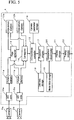
- Fig. 5 is an electronic block diagram of the traffic flow measuring device;
- Fig. 6 shows one example of pictures taken by the respective cameras;
- Fig. 7 shows a Laplacian filter employed in the measuring device;
- Fig. 8 shows one example of extraction of edge pictures;
- Fig. 9 shows one example of a corresponding process method;
- Fig. 10 shows a result of a difference degree operation for the corresponding process;
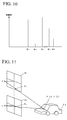
- Fig. 11 shows a principle of a trigonometrical measurement;
- Fig. 12 illustrates a projecting method about three dimensional coordinates;
- Fig. 13 shows a result of projection to a virtual perpendicular plane;
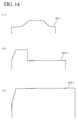
- Fig. 14 shows lateral shape models;
- Fig. 15 shows other shape models;
- Fig. 16 shows a result of a comparison discrimination process;
- Fig. 17 shows a data construction in a process result storage;
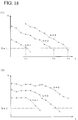
- Fig. 18 shows graphs representing correspondence of detected values of vehicle positions at the respective processing time points;
- Fig. 19 shows an electronic block diagram of a traffic flow measuring device as a second embodiment of this invention;
- Fig. 20 shows a result of a characteristic selection;
- Fig. 21 shows a result of extraction of representative points;
- Fig. 22 shows a result of computation of three dimensional coordinates about the representative points;
- Fig. 23 shows a result of a grouping process about the respective three dimensional coordinates of Fig. 22;
- Fig. 24 shows a result of projection about the three dimensional coordinates for each group;
- Fig. 25 shows a method for setting an area for weighting;
- Fig. 26 shows an area for scanning models;
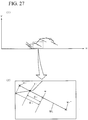
- Fig. 27 shows a principle of weighted comparison processing method;
- Fig. 28 shows a conception of evaluation values of the respective projection points;
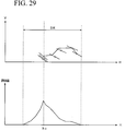
- Fig. 29 shows a result of a comparison discrimination process;
- Fig. 30 shows an electronic block diagram of a traffic flow measuring device as a third embodiment of this invention;
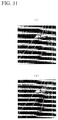
- Fig. 31 exemplarily shows input pictures from the respective cameras;
- Fig. 32 exemplarily shows input pictures from the respective cameras;
- Fig. 33 shows a result of a binary process about the respective input pictures of Fig. 31;
- Fig. 34 shows a result of a binary process about the respective input pictures of Fig. 31;
- Fig. 35 shows a result of computation for three dimensional coordinates of the characteristic points;
- Fig. 36 shows a result of computation for three dimensional coordinates of the characteristic points;
- Fig. 37 shows an installation of a parking lot observing device as a fourth embodiment of this invention;
- Fig. 38 shows a schematic block diagram of the parking lot observing device;
- Fig. 39 shows one example of input pictures from the respective cameras;
- Fig. 40 shows one example of edge pictures;
- Fig. 41 shows a relation between the computation result of three dimensional coordinates and the projecting process;
- Fig. 42 shows a result of projection;
- Fig. 43 shows shapes of models;
- Fig. 44 shows a schematic block diagram of a parking lot observing device as a fifth embodiment of this invention; and
- Fig. 45 shows a result of grouping three dimensional coordinates.
- There will be disclosed five embodiments of this invention hereinafter, in which a pair of
cameras - Referring, now, to Fig. 1, there is shown a perspective view of a traffic flow measuring device as a first embodiment of this invention. The traffic flow measuring device includes the pair of
cameras controller 4 which are mounted on an F-shapedprop 2 standing on one side of aroad 1. Pictures obtained by thecameras controller 4 to discriminate the number and the type of passing vehicles, measure the speed of a specific vehicle, and detect an illegally parking vehicle for each lane of theroad 1. - The
prop 2 includes a pair of cross rods above theroad 1, and thecameras vertical stick 6 fixed across the cross rods. Thecontroller 4 is mounted near a base portion of theprop 2 for the convenience of maintenance and inspection. - Fig. 2 shows one example of installation of the
cameras cameras vertical stick 6 through a short reinforcingplate 8. The mounting positions of thecameras plate 8 at its one end is connected with the plate 7 at a middle point between the supporting points for thecameras vertical stick 6 to hold the inclination of the plate 7. - In Fig. 3 there is shown another installation of the
cameras cameras support plates vertical stick 6, and theplates cameras cameras upper camera 3a is positioned behind the taking picture plane of thelower camera 3b, the picture taken by thecamera 3a shall be enlarged according to the backward distance prior to entry to an image processing described later. - The
cameras box unit 25 which is supported by support plate 7 and reinforcingplate 8 as shown in Fig. 4. - The road is picked up by two cameras in this embodiment, but, if desired, may be picked up by three or more cameras. The prop mounted by the cameras is not limited to the F-shaped
prop 2, but may utilize existing telephone pole or light pole by modification if necessary. - In Fig. 5 there is shown an electronic block diagram of the traffic flow measuring device. The
controller 4 includes A/D converters 10a and 10b, picture memories 11a and 11b,edge memories 12a and 12b, anedge extracting unit 13, a correspondingunit 14, a three-dimensional coordinatecomputing unit 15, acamera parameter storage 16, aprojection process unit 17, a trafficlane data storage 18, amodel data storage 19, acomparison discriminating unit 20, aprocess result storage 21, and atracing process unit 22. - The A/
D converters 10a and 10b convert analog video signals generated from thecameras - A picture of the
camera 3a stored in the picture memory 11a is called as "first picture", and a picture of thecamera 3b stored in the picture memory 11b is called as "second picture", hereinafter. - Fig. 6 shows at (1) and (2) one example of the first and second pictures in which picture data including traffic lanes, vehicles, and the shadows of vehicles on the road are produced.
- The
edge extracting unit 13 extracts the first and second pictures from the picture memories 11a and 11b to generate edge pictures. In theunit 13, each picture is scanned by a Laplacian filter shown in Fig. 7 to extract zero-crossing points, and the coordinates of the zero-crossing points are computed to generate a binary edge picture in which the pixels of the computed coordinates are black pixels and other pixels are white pixels. The edge extracting process is not limited to the use of the Laplacian filter, but may employ other edge extracting filter such as a Sobel filter. - An edge picture generated about the first picture (hereinafter called as "first edge picture") is stored in the first edge picture memory 12a, and an edge picture generated about the second picture (hereinafter called as "second edge picture") is stored in the second
edge picture memory 12b. - Fig. 8 shows at (1) and (2) results of the above-mentioned edge extracting process about the first and second pictures shown in Fig. 6 (1) and (2), in which edge components corresponding to outlines of the respective vehicles and their shadows are extracted.
- Upon the generation of the edge pictures and the storage into the
edge picture memories 12a and 12b, a corresponding operation for corresponding edge constructive points within the respective edge pictures is executed by the correspondingunit 14, and the three-dimensional coordinates about the respective edge constructive points corresponded by the three-dimensional coordinatecomputing unit 15 are computed. - Fig. 9 shows at (1) to (4) a concrete example of the corresponding process in the corresponding
unit 14. First, theunit 14 extracts a predetermined edge constructive point p from the first edge picture E1 in the edge picture memory 12a as shown at (1) of Fig. 9. Next, theunit 14 aims at the second edge picture E2 in theedge picture memory 12b as shown at (2) of Fig. 9 to extract edge constructive points q1, q2, q3, q4, and q5 located on an epipolar line L of the edge constructive point p as the corresponding candidate points of the edge constructive point p in the edge picture E2. Thecameras - The corresponding
unit 14 sets a predetermined size of window Wu centered at a point P positioning at the same coordinates (x, yu) as that of the edge constructive point p on the first picture G1 in the first picture memory 11a as shown at (3) of Fig. 9. Theunit 14 also extracts points Q1-Q5 located on the same coordinates (x, y1), (x, y2), (x, y3), (x, y4), and (x, y5) as those of the corresponding candidate points q1-q5 on the second picture G2 in the second picture memory 11b as shown at (4) of Fig. 9, and sets on the second picture G2 the same size of windows W1-W5 respectively centered at the points Q1-Q5 as the size of the window Wu. - Upon setting the respective windows, the corresponding
unit 14 respectively executes the following equation (1) about the windows W1-W5 on the second picture to compute difference degrees C between the respective windows and the window Wu on the first picture:
- The corresponding
unit 14 compares the difference degrees C between the respective windows W1-W5 and the window WU, and the window having the smallest different degree is discriminated as the window corresponding to the window WU. A point qL on the same coordinates (x, yL) in the second edge picture as that of the central point QL of the corresponding window is discriminated as a corresponding point of the edge constructive point p of the first edge picture. - Fig. 10 shows a result of computation about difference degrees of the respective windows W1-W2 with the window WU. In this graph the difference degree of the second window W2 is the smallest, so that q2 is regarded as the corresponding point in the second edge picture corresponding to the edge constructive point p. Instead of the above-mentioned difference degrees, normalized cross correlation operation with the window WU may be so executed for each of the respective windows W1-W5 that the window providing the largest correlation value can be regarded as the window corresponding to the window WU.
- Upon completing the above-mentioned corresponding process about all edge constructive points within both edge pictures, the three-dimensional coordinate
computing unit 15 receives the coordinates (x, yU) and (x, yL) of the edge constructive points p and q corresponding to the respective edge pictures E1 and E2 and the parameters of thecameras camera parameter storage 16 to compute three-dimensional coordinates corresponding to the respective edge constructive points based on the principle of the trigonometrical measurement. - Fig. 11 shows the principle of the trigonometrical measurement. A point P shows a predetermined characteristic point on an object 23 (vehicle in this embodiment) on a road. Object point images PU and PL of the characteristic point P appear on the first picture G1 and the second picture G2, in which U represents the focal point of the
camera 3a and L represents the focal point of thecamera 3b. - The three dimensional coordinates (X, Y, Z) corresponding to the object point images PU and PL correspond to the spatial position of the characteristic point P. The execution of the above-mentioned method about all characteristic points of the
object 23 provides measurement of a three-dimensional shape of theobject 23. - Based on this principle, the three-dimensional coordinate
computing unit 15 executes the following equations (2)-(4) to compute the three-dimensional coordinates corresponding to the respective edge constructive points:
second camera 3b, and θ represents an angle of depression of each camera. - Upon computation of the three-dimensional coordinates corresponding to all edge constructive points, the
projection process unit 17 sets a virtual perpendicular plane along a longitudinal direction of the road to project the three-dimensional coordinates computed by the three-dimensional coordinatecomputing unit 15 on the virtual perpendicular plane. - Fig. 12 shows one example of a projecting method, in which X, Y and Z are spatial coordinate axes. The virtual perpendicular plane (shown by a reference mark "R") is defined in a position along the road by a horizontal axis H in parallel with a Z-axis and a vertical axis V in parallel with a Y-axis. When the virtual perpendicular plane R is viewed from the front, the respective edge components viewed from the side of the road are extracted.
- The traffic
lane data storage 18 stores data representing a positional relationship with each traffic lane on the road viewed from the observation position (viz., x-coordinate and z-coordinate), and the three dimensional coordinates can be projected for each lane by projecting by referring to the stored data. Instead of the trafficlane data storage 18 there may be employed a later describedclassification processing unit 32 between the three-dimensional coordinatecomputing unit 15 and theprojection process unit 17 to divide the respective three dimensional coordinates into groups based on the positional relation in a width direction of the road and project for each group. - The
model data storage 19 stores two-dimensional data MD1, MD2, MD3 ... respectively representing models of side views about a plural kinds of vehicles, such as a sedan, a truck, a bus and so forth, as shown in Fig. 14 (1), (2) and (3). Thecomparison discriminating unit 20 sequentially scans these side view models (called simply as "model", hereinafter) about the virtual perpendicular plane R to discriminate a subject represented by the projection points appearing on the virtual perpendicular plane R. - The models of the respective vehicles are not necessary to be limited to the whole side views, but may be two-dimensional data respectively representing partial side views (portions represented by solid lines) of the models as shown in Fig. 15 (1) to (3).
- Fig. 16 shows one example of a result of a comparison processing in reference to the model MD1 of Fig. 14 (1) about the projection result shown in Fig. 13.
- The
comparison discriminating unit 20 regards an original point O of the virtual perpendicular plane R as an initial position, sequentially scans the model MD1 in the H-axial direction, and counts the number n of projection points included in the model MD1 in the respective scanning positions. When the number n of the projection points is equal to or larger than a predetermined threshold value TH, theunit 20 execute the following equation (5) to compute an evaluation value Eh of a projected portion overlapped with the model MD1:

- When the number n of the projection points overlapped with the model is less than the threshold value TH, the
comparison discriminating unit 20 sets the maximum value MAX in the evaluation value in the scanning position. Theunit 20 scans the virtual perpendicular plane R with all models to compute evaluation values at the respective scanning positions, discriminates the vehicle type of the model providing the minimum evaluation value among the computed evaluation values as the type of the vehicle of the projected portion, and determines the coordinates ho (shown in Fig. 16) at the time point when the minimum evaluation value is obtained as the beginning position of the vehicle. - The results of this discrimination is stored in the
process result storage 21. Subsequently, the similar operation is executed every predetermined time period, and the process results are sequentially accumulated in theprocess result unit 21. Theunit 21 is provided with a table TB (called as "process result storage table TB", hereinafter) for storing the beginning positions (the coordinates ho of Fig. 16) of the vehicles extracted for the respective traffic lanes, and the values representing the beginning positions of the extracted vehicles are sequentially stored in theunit 21 every processing time t1, t2, t3, ..., as shown in Fig. 17. - The
tracing process unit 22 reads out the positions of the vehicle detected every processing time from the process result storage table TB, and discriminates temporal change of the positions of the vehicle by respectively corresponding the read out positions to the detected values at the just one step before processing time. - Assuming that the number J of vehicles are detected at a processing time ti and the beginning position of the "j"th (1≦j≦J) detected vehicle is hj(ti), the
tracing process unit 22 extracts the detection result representing the minimum distance with hj(ti) in the positions having differences from the position hj(ti) less than a predetermined threshold value in the detection results at the subsequent processing time tj+1, and the extracted position is discriminated as the beginning position hj(ti+1) of the "j"th vehicle at the processing time ti+1. - This corresponding process finishes when the data satisfying the above-described conditions exceeds a predetermined detection line Det. (shown in Fig. 18 (1) and (2)). When there is no data satisfying the conditions at the processing time ti+1, the
tracing process unit 22 stops the corresponding process. Fig. 18 shows at (1) and (2) changes of positions of the respective vehicles discriminated by the corresponding process. The marks "x" represent plots of detection results every processing time, the loci shown in dotted lines represent the corresponded detection results, viz., the positional changes of the respective vehicles. - The detection line Det. corresponds to a predetermined horizontal line on the road, and the
tracing process unit 21 executes a count process about passing vehicles at the time points (t1, t2, and t3 in Fig. 18 (1)) when the respective loci cross the detection line Det., and samples the detection values just after the passing and just before several-times detection results to compute the passing speed of the vehicle based on the detection results. - Assuming that N-pieces of detection values are sampled about the u-th locus (u=1, 2, 3 ...) and the coordinates of the n-th (1 ≦ n ≦ N) sampled detection value are (tun, hun), the passing speed Vu of the vehicle represented by the locus is depressed by the following equation:

- When the respective vehicles moves smoothly, the loci shown at (1) of Fig. 18 is obtained. When signal waiting or traffic congestion happens, the detection values at the respective processing times little change as shown at (2) of Fig. 18. According to this method, flat data like shadows of vehicles are not erroneously detected as a vehicle, and vehicles are precisely discriminated to provide a high accurate measurement. In addition to the detection of speed of moving vehicles, the vehicle or substance stopping on the road can be detected, whereby traffic congestion, illegal parking and obstacles can be precisely detected.
- Returning to Fig. 19, there is shown an electronic block diagram of a traffic flow measuring device as a second embodiment of this invention. This device also discriminates vehicles passing on the respective traffic lanes from the pictures taken by two
cameras controller 4 is designed to include acharacter selecting unit 30, a representativepoint extracting unit 31, aclassification processing unit 32, a coordinateselection unit 33, and a weightingarea setting unit 34, whereby the processing time is decreased and a high accurate measuring operation is performed. - The
character selecting unit 30 is disposed to chose a characteristic portion for a processing candidate from the respective edge pictures stored in theedge picture memories 12a and 12b, wherein a portion where a predetermined number or more edge constructive points are connected is extracted as a characteristic portion for each edge picture. - In the chosen characteristic portions, the representative
point extracting unit 31 extracts an edge constructive point corresponding to a central point of each characteristic portion as one point representing the characteristic portion. - Fig. 20 shows at (1) and (2) a result of a characteristic selecting operation about the edge pictures shown at (1) and (2) of Fig. 8. Fig. 21 shows a result of extraction of representative points (shown by marks "x") in the picture within an area surrounded by a dotted line at (2) of Fig. 20. Only these representative points are processed in the subsequent process, whereby the processing speed is fairly improved.
- Corresponding
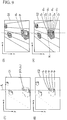
unit 14 executes a corresponding operation between the respective edge pictures about the extracted respective representative points, and three dimensional coordinatecomputing unit 15 computes three-dimensional coordinates about the respective representative points by utilizing the results of corresponding. Theclassification processing unit 32 executes a clustering operation employing the respective x-coordinates about the computed three dimensional coordinates, and the respective representative points are divided into groups based on the results of the clustering. - Fig. 22 shows one example of a result of computation of three dimensional coordinates about the respective representative points, in which a plurality of representative points are respectively extracted in a space near a boundary of traffic lanes L1 and L2 and on an X-Z plane contacting the first lane L1.
- Fig. 23 shows a result of a grouping process about the respective representative points of Fig. 22, in which the respective representative points located near the boundary of traffic lanes L1 and L2 are classified to a first group G1 and the respective representative points located on the X-Z plane are classified to a second group G2.
- Upon the completion of this grouping process, the
projection process unit 17 executes a projecting operation about the three dimensional coordinates of the representative points included in each group, for each group. - The coordinate
selection unit 33 selects a representative point as a final processed object from the projection process results in each group. In this embodiment, a y-coordinate corresponding to a position of bumper of a vehicle is designed to be a threshold value, and theunit 33 chooses the point having height data higher than this threshold value among the representative points projected on the virtual perpendicular plane R as a constructive point of the vehicle. - Fig. 24 shows at (1) and (2) a result of projection after the above-described coordinate selection process about the respective groups G1 and G2, and the respective projection points in the group G2 are removed as noise.
- According to this process, the projection points relating to the object on the road plane such as the shadow of a vehicle are removed, but the weighting
area setting unit 34 sets a weighting area on the remained projection points as described later. Subsequently, thecomparison discriminating unit 20 compares the respective points included in the set weighting area with the respective models stored in themodel data storage 19. - The setting operation of the weighting area and the comparison operation will be described in detail hereinafter in conjunction with Figs. 25 to 29.
- About each projection point, the weighting
area setting unit 34 sets a line segment WL in which the projection point is expanded by a predetermined length in a direction based on a central camera parameters as an area corresponding to a width of errors developed on measuring the above-mentioned three-dimensional coordinates. - Assuming that the "i"th projection point Wi has the coordinates (hi, vi) on the H-V plane and y-coordinates of a point corresponding to the projection point Wi in the respective input pictures obtained from the
cameras 
- The
comparison discriminating unit 20 sequentially reads the respective models M stored in themodel data storage 19, and sets a range SR including two or more projection points within a width r of model M as a scanning range of model as shown in Fig. 26. - Next, as shown in Fig. 27, the
unit 20 seeks the coordinates of the intersection point Zi of the above-mentioned expanded line segment WL and the model M for each scanning position hi of the model M within the scanning range R, and computes a distance Di between the intersection point Zi and the projection point Wi, a distance Ei between the projection point Wi and an end point Wi + (or Wi -) located on the side of the intersection point Zi. Theunit 20 applies a ratio of Di and Ei computed about the projection point Wi to the following equation (12), computes a probability spi about the actual existence of model M at the intersection point Zi as an evaluation value of the projection point Wi, and computes summation SPi of these evaluation values spi (shown in Fig. 28) as a goodness of fit with the model of the projection data in the scanning position hi:
- According to the above-mentioned method, the comparison weighted in accordance with the distance between each intersection point Zi and projection point Wi is executed between the model M and the respective expanded line segment WL, and errors on computing three-dimensional coordinates are removed. The construction for this weighted comparison may be applied to the device of the first embodiment.
- Fig. 29 shows a result of a comparison process in the scanning region SR. The
comparison discriminating unit 20 discriminates that the beginning portion of the vehicle type corresponding to the model M is located in a scanning position ho where the evaluation value SPi becomes the maximum value. - The result of the discrimination is stored into the
process result storage 21. The operation of temporal positional changes and speed measurement of the respective vehicles is executed by thetracing process unit 22 in the same way as that of the first embodiment. - In the foregoing two embodiments edge constructive points are extracted from the input pictures from the
cameras - Fig. 30 shows an electronic block diagram of a traffic flow measuring device which can measure a traffic flow at night as a third embodiment of this invention.
Controller 4 of this embodiment includes abinary converter 35 and a binary picture memories 36a and 36b, instead of theedge extracting unit 13 and theedge picture memories 12a and 12b in the first embodiment. - Figs. 31 (1) and (2) and Figs. 32 (1) and (2) show examples of input pictures from the
respective cameras - The
binary converter 35 is designed to convert the pixels having the luminance values exceeding a predetermined threshold value into black pixels in the input pictures stored in the memories 11a and 11b, and the converted binary pictures are stored in the binary picture memories 36a and 36b. - Figs. 33 (1) and (2) show the binary pictures converted from the input pictures of Figs. 31 (1) and (2), and Figs. 34 (1) and (2) show the binary pictures converted from the input pictures of Figs. 32 (1) and (2), in which the portions of light are extracted as black pixels.
- The corresponding
unit 14 executes a corresponding process between pictures about the black pixels in the respective binary pictures as mentioned above. The three-dimensional coordinatecomputing unit 15 computes three-dimensional coordinates about the respectively corresponded pixels. As a result, the positions of light portions included in the respective input pictures are extracted to be applied to thecomparison discriminating unit 20, - The
model data storage 19 stores data representing the numbers and positions of lights for each vehicle such as a compact car, a motorcycle and large size car, and thecomparison discriminating unit 20 compares the storage data with the computation results by three dimensional coordinatecomputing unit 15 to discriminate which type of vehicle is located in which position. - Fig. 35 shows a result of computation for three dimensional coordinates employing the binary pictures at (1) and (2) of Fig. 33, and Fig. 36 shows a result of computation for three dimensional coordinates employing the binary pictures at (1) and (2) of Fig. 34. The mark "·" represents a point corresponding to a central point of each characteristic portion (called as "characteristic point" hereinafter). The
comparison discriminating unit 20 has a recognition area from a y-coordinate corresponding to a height position of a standard bumper until a predetermined height position, and extracts a characteristic points having a y-coordinate within the recognition area as a characteristic point candidate. Theunit 20 compares positional relations of the extracted characteristic points with the storage data in themodel data storage 19 to discriminate the types and positions of the vehicles on road. The dotted lines in Figs. 35 and 36 represent boundary lines of traffic lanes based on positional information stored in the trafficlane data storage 18, and based on this positional information the traffic lane located by the discriminated vehicle is identified. - When there exist a pair of characteristic points (for example, pairs of characteristic points O1-O2 and O3-O4 of Fig. 35) located in a position corresponding to a position just above a bumper and in parallel at an interval corresponding to a width of headlights of an ordinary automobile in a width direction of the road, the
unit 20 recognizes the positions of these characteristic points as the beginning positions of ordinary automobiles. When there exists a single characteristic point (for example, a characteristic point O5) having height data corresponding to a position just above a bumper, theunit 20 discriminates that a motorcycle is located in the position of the characteristic point. When the interval of the pair of characteristic points corresponding to headlights is larger than the interval of the headlights of ordinary automobile and a plurality of characteristic points (the respective characteristic points of Fig. 36) exist around the pair of characteristic points, theunit 20 discriminates that these characteristic points represent a large size vehicle, and further discriminates the type (truck, van, and bus) of the vehicle in view of the positional relations of the respective characteristic points. - When the shadows of headlights reflected on a wet road in the rain and night lights or traffic signs along a road are extracted as characteristic points, the y-coordinates of these characteristic points are out of the recognition area and regarded as not the characteristic points expressing any vehicle. Thus, any risk of erroneous detection of other materials than vehicles as a vehicle, and even at night vehicles can be precisely discriminated.
- The results of the
comparison discriminating unit 20 are sequentially stored into theprocess result storage 21. Subsequently, the same operations as those of the first and second embodiments are executed. - The foregoing embodiments relate to traffic flow measuring devices. The above-mentioned vehicle measuring method is not limited to the moving vehicles, but may be applied to parking vehicles.
- Fig. 37 shows a parking lot observing device as a fourth embodiment of this invention. The parking lot observing device is disposed near a parking lot having a plurality of parking sections (two sections in this embodiment) to discriminate the parking of vehicles. The parking lot is provided with the two
parking sections 40 at a predetermined interval. Each parking section is divided into four sections in a longitudinal direction (in a direction marked with an arrow mark A in Fig. 37), and into two sections in a width direction, whereby eight parking areas AR are provided. - In this embodiment, the respective parking areas AR are observed for each
parking section 40, and observation devices each consisting ofcameras parking section 40. Thecameras - Fig. 38 shows a schematic block diagram of the parking lot observing device. The controller 4' includes A/
D converters 10a and 10b, picture memories 11a and 11b,edge memories 12a and 12b, anedge extracting unit 13, a correspondingunit 14, a three-dimensional coordinatecomputing unit 15, acamera parameter storage 16, aprojection process unit 17, amodel data storage 19, and acomparison discriminating unit 20, which are the same components as those of Fig. 5. The controller 4' further includes anarea data storage 42 for storing positional information of the respective parking areas AR (for example, coordinates of the respective vertexes). - When input pictures as shown in Fig. 39 (1) and (2) are stored in the memories 11a and 11b, the
edge extracting unit 13 extracts edge constructive points in a horizontal direction about the input pictures in the same method as those of the above-mentioned first and second embodiments. As a result, edge pictures as shown in Fig. 40 (1) and (2) are produced, and stored in theedge picture memories 12a and 12b. - The corresponding
unit 14 and the three-dimensional coordinatecomputing unit 15 execute a corresponding operation between pictures about each edge constructive point and compute three-dimensional coordinates of each corresponded point. - The
projection process unit 17 sets a virtual perpendicular plane R' along the longitudinal direction A of the parking section, viz., a width direction of each parking area AR, and projects the computed three-dimensional coordinates on the perpendicular plane R'. This projection operation is executed based on the storage data in thearea data storage 42 for each line of theparking section 40. - Fig. 41 shows one example of the above projection operation, and Fig. 42 shows a front view of the virtual perpendicular plane R' applied by the projection operation. The projection data representing a front shape or a rear shape of a vehicle within each parking area is extracted separately.
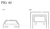
- As shown in Fig. 43 (1) and (2), the
model data storage 19 stores model of a front shape or a rear shape for each type of vehicle, and thecomparison discriminating unit 20 sequentially scans the respective models on the virtual perpendicular plane R' to discriminate the vehicles in the same way as one of the above-mentioned first embodiment. - If the
unit 20 discriminates the position of the vehicle corresponding to one of the models, it collates the storage data in thearea data storage 42, recognizes which parking area corresponds to the discriminated position, and eventually transmits to an administrative center the data representing which type of vehicle parks in which parking area. - Though in this embodiment the virtual perpendicular plane R' is set in the width direction of the parking area and a front shape of each vehicle is projected, the virtual perpendicular plane may be set in a longitudinal direction of the parking area to project a side shape of each vehicle. Moreover, though in this embodiment the projection operation is simultaneously executed about parking areas in the same line, it may be individually executed for each parking area.
- If in addition to this parking lot observation process the vehicles moving on peripheral paths around each
parking section 40 are discriminated by employing the above-mentioned first and second embodiments, a vehicle going to park and a vehicle going to leave the parking lot can be discriminated and total administration of the parking lot is possible. - The parking lot observing device of this embodiment discriminate vehicles based on the projecting operation of three-dimensional coordinates, but may be so constructed to discriminate vehicles based on height data shown by the respective coordinates computed instead of the projection operation.
- Fig. 44 shows so constructed parking lot observing device as a fifth embodiment of this invention. Controller 4' is provided with a parking car
existence discriminating unit 45 for discriminating, based on the computed three dimensional coordinates and the positional information of each parking area, whether or not any vehicle is parking at each parking area. Other components having the same constructions as those of the foregoing embodiments are represented by the same reference numerals and their detailed explanation is omitted for simplification. - The parking car
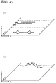
existence discriminating unit 45 divides the respective computed three-dimensional coordinates into groups for each parking area based on the positional information of the respective parking areas AR stored in thearea data storage 42. For example, if the computation result of three dimensional coordinates shown in Fig. 41 is divided into groups, it is shown in Fig. 45 (1) and (2). Moreover, about the "m"th classified group gm, theunit 45 computes the number PTm of three-dimensional coordinate points included in the group and an average value ADm of height data of these coordinate points, compares the computed data PTm and ADm with a predetermined threshold value to discriminate whether or not any vehicle exists within the parking area AR corresponding to the group gm. - The number PTm of the three-dimensional coordinate points is compared with a threshold value TH1 which is set corresponding to an average number of the edge constructive points of a vehicle. The height average value ADm is compared with the two kinds of threshold values TH2 and TH3, in which the threshold value TH2 is set by a value corresponding to an average height of ordinary automobiles and the threshold value TH3 is set by a value corresponding to an average height of large sized vehicles.
- When in the group gm the above-mentioned PTm exceeds the threshold value TH1 and ADm is between the threshold values TH2 and TH3, the
unit 45 discriminates that an ordinary car exists at the parking area AR corresponding to the group gm. When PTm exceeds the threshold value TH1 and ADm is equal to or larger than the threshold value TH2, theunit 45 discriminates that a large sized vehicle exists at the parking area AR corresponding to the group gm. - When PTm is equal to or smaller than the threshold value TH1 or ADm is equal to or smaller than the threshold value TH2, the
unit 45 discriminates that no vehicle exists at the corresponding parking area. - The device in the foregoing embodiments discriminates vehicles on road or within parking area, but may be modified to discriminate various kinds of objects other than vehicles and employ same methods to measure temporal positional changes of the objects.
- While the invention has been described and illustrated with respect to certain embodiments which give satisfactory results, it will be understood by those skilled in the art, after understanding the purpose of the invention, that various other changes and modifications may be made without departing from the spirit and scope of the invention, and it is therefore, intended in the appended claims to cover all such changes and modifications.
Claims (16)
- An object observing method for observing an object comprisinga first step of simultaneously taking a picture by two or more cameras directed toward a predetermined observation position to extract a characteristic portion in each of the respective taken pictures,a second step of corresponding said extracted characteristic portion in the picture to the pictures,a third step of measuring said corresponded characteristic portion in three-dimensions to extract its three-dimensional coordinates,a fourth step of projecting the three-dimensional coordinates of said extracted characteristic portion on a virtual perpendicular plane vertically positioning on a plane contacting said object, anda fifth step of comparing said projected data with predetermined two-dimensional model data to discriminate said object.
- An object observing method according to claim 1, in which said fourth step of projecting is a step of dividing said three-dimensional coordinates of the respective characteristic portions into groups based on a positional relationship on a plane contacted by said object, and of projecting the three-dimensional coordinates included in the groups on said virtual perpendicular plane for each of the groups.
- An object observing method according to claim 1 or 2, in which said fifth step of comparing is a step of setting a predetermined region including the respective projection points formed on said virtual perpendicular plane by the projecting processing of said fourth step, and of weighting the respective points based on the positional relationship of the respective points in said set region with said projection points to be compared with said two-dimensional model data.
- An object observing method for observing an object comprisinga first step of simultaneously taking a picture by two or more cameras directed toward a predetermined observation position to extract a characteristic portion in each of the respective taken pictures,a second step of specifying a point showing the representative characteristics about said extracted characteristic portion of the picture,a third step of corresponding said specified representative point to a picture,a fourth step of measuring in three-dimensions for each of said corresponded representative points to extract its three-dimensional coordinates of the respective representative points,a fifth step of projecting the three-dimensional coordinates of said extracted representative points on a virtual perpendicular plane vertically positioning on a plane contacting said object, anda sixth step of comparing said projected data with predetermined two-dimensional model data to discriminate said object.
- An object observing method according to claim 1, in which said fifth step of projecting is a step of dividing said three-dimensional coordinates of the respective representative points into groups based on a positional relationship on a plane contacted by said object, and of projecting the three-dimensional coordinates included in the groups on said virtual perpendicular plane for each of the groups.
- An object observing method according to claim 4 or 5, in which said sixth step of comparing is a step of setting a predetermined region including the respective projection points formed on said virtual perpendicular plane by the projecting processing of said fifth step, and of weighting the respective points based on the positional relationship of the respective points in said set region with said projection points to be compared with said two-dimensional model data.
- An object observing device for observing an object comprising
two or more cameras directed toward a predetermined observation position,
characteristic extracting means for extracting a characteristic portion in each of the respective pictures simultaneously taken by said cameras,
corresponding means for corresponding the extracted characteristic portions of the respective pictures extracted by said characteristic extracting means to the pictures,
coordinate extracting means for three-dimensionally measuring the characteristic portions corresponded by said corresponding means to extract the three-dimensional coordinates of the characteristic portions,
storage means for storing two-dimensional model data of said object,
projecting means for setting a virtual perpendicular plane vertically positioning on a plane contacted by said object to project the three-dimensional coordinates of the characteristic portions extracted by said coordinate extracting means on said virtual perpendicular plane, and
comparing means for comparing the results of projection by said projecting means with said two-dimensional model data stored in said storage means. - An object observing device according to claim 7, in which said projecting means divides said three-dimensional coordinates of the respective characteristic portions extracted by said coordinate extracting means into groups based on a positional relationship on a plane contacted by said object, and projects the three-dimensional coordinates included in the groups on said virtual perpendicular plane for each of the groups.
- An object observing device according to claim 7 or 8, in which said comparing means sets a predetermined region including the respective projection points formed on said virtual perpendicular plane by the projecting processing of said projecting means, and weights the respective points based on the positional relationship of the respective points in said set region with said projection points to be compared with said two-dimensional model data.
- An object observing device for observing an object comprising
two or more cameras directed toward a predetermined observation position
characteristic extracting means for extracting a characteristic portion in each of the respective pictures simultaneously taken by said cameras,
representative point specifying means for specifying points respectively showing representative characteristics about the characteristic portions of the respective pictures extracted by said characteristic extracting means,
corresponding means for corresponding the respective representative points specified by said representative point specifying means to the pictures,
coordinate extracting means for three-dimensionally measuring for each of the representative points corresponded by said corresponding means to extract the three-dimensional coordinates of the respective representative points,
storage means for storing two-dimensional model data of said object,
projecting means for setting a virtual perpendicular plane vertically positioning on a plane contacted by said object to project the three-dimensional coordinates of the representative points extracted by said coordinate extracting means on said virtual perpendicular plane, and
comparing means for comparing the results of projection by said projecting means with said two-dimensional model data stored in said storage means. - An object observing device according to claim 10, in which said projecting means divides said three-dimensional coordinates of the respective representative points extracted by said coordinate extracting means into groups based on a positional relationship on a plane contacted by said object, and projects the three-dimensional coordinates included in the groups on said virtual perpendicular plane for each of the groups.
- An object observing device according to claim 10 or 11, in which said comparing means sets a predetermined region including the respective projection points formed on said virtual perpendicular plane by the projecting processing of said projecting means, and weights the respective points based on the positional relationship of the respective points in said set region with said projection points to be compared with said two-dimensional model data.
- A traffic flow measuring device for observing a flow of a vehicle on a road to measure traffic flow data on the road based on time change of the observation results comprising
two or more cameras disposed above the road directed toward an observation position on the road,
characteristic extracting means for extracting a characteristic portion in each of the respective pictures simultaneously taken by said cameras for each predetermined time period,
corresponding means for corresponding the extracted characteristic portions of the respective pictures extracted by said characteristic extracting means to the pictures,
coordinate extracting means for three-dimensionally measuring the characteristic portions corresponded by said corresponding means to extract the three-dimensional coordinates of the characteristic portions,
projecting means for setting a virtual perpendicular plane along the road to project the three-dimensional coordinates of the characteristic portions extracted by said coordinate extracting means on said virtual perpendicular plane,
storage means for storing a shape model of a side face of each vehicle about a plurality types of vehicles,
vehicle discriminating means for comparing the projection results by said projecting means with the respective models stored in said storage means to discriminate vehicles on the road, and
observing means for sequentially tracing the discrimination results by said vehicle discriminating means to observe the flow of the vehicles on the road. - A traffic flow measuring device for observing a flow of a vehicle on a road to measure traffic flow data on the road based on time change of the observation results comprising
two or more cameras disposed above the road directed toward an observation position on the road,
characteristic extracting means for extracting a characteristic portion in each of the respective pictures simultaneously taken by said cameras for a predetermined time period,
corresponding means for corresponding the extracted characteristic portions of the respective pictures extracted by said characteristic extracting means to the pictures,
coordinate extracting means for three-dimensionally measuring the characteristic portions corresponded by said corresponding means to extract the three-dimensional coordinates of the characteristic portions,
projecting means for setting a virtual perpendicular plane along the road to project the three-dimensional coordinates of the characteristic portions extracted by said coordinate extracting means on said virtual perpendicular plane,
vehicle discriminating means for discriminating vehicles on the road by employing a relative positional relationship of three dimensional coordinates satisfying a predetermined height condition among the three dimensional coordinates of the respective characteristic portions extracted by said coordinate extracting means, and
observing means for sequentially tracing the discrimination results by said vehicle discriminating means to observe the flow of the vehicles on the road. - A parking lot observing device for observing vehicles parking within a predetermined shape of area comprising
two or more cameras disposed above said area directed toward said area,
characteristic extracting means for extracting a characteristic portion in each of the respective pictures simultaneously taken by said cameras for a predetermined time period,
corresponding means for corresponding the extracted characteristic portions of the respective pictures extracted by said characteristic extracting means to the pictures,
coordinate extracting means for three-dimensionally measuring the characteristic portions corresponded by said corresponding means to extract the three-dimensional coordinates of the characteristic portions,
projecting means for setting a virtual perpendicular plane vertically standing on a vehicle parking plane of said area to project the three-dimensional coordinates of the characteristic portions extracted by said coordinate extracting means on said virtual perpendicular plane,
storage means for storing a shape model of a side face of each vehicle about a plurality types of vehicles, and
vehicle discriminating means for comparing the projection results by said projecting means with the respective models stored in said storage means to discriminate vehicles on the area. - A parking lot observing device for observing vehicles parking within a predetermined shape of area comprising
two or more cameras disposed above said area directed toward said area,
characteristic extracting means for extracting a characteristic portion in each of the respective pictures simultaneously taken by said cameras for a predetermined time period,
corresponding means for corresponding the extracted characteristic portions of the respective pictures extracted by said characteristic extracting means to the pictures,
coordinate extracting means for three-dimensionally measuring the characteristic portions corresponded by said corresponding means to extract the three-dimensional coordinates of the characteristic portions, and
discriminating means for discriminating vehicles within said area by employing three dimensional coordinates satisfying a predetermined height condition among the three dimensional coordinates of the respective characteristic portions extracted by said coordinate extracting means.
Applications Claiming Priority (3)
| Application Number | Priority Date | Filing Date | Title |
|---|---|---|---|
| JP145546/95 | 1995-05-18 | ||
| JP14554695 | 1995-05-18 | ||
| JP14554695 | 1995-05-18 |
Publications (2)
| Publication Number | Publication Date |
|---|---|
| EP0747870A1 true EP0747870A1 (en) | 1996-12-11 |
| EP0747870B1 EP0747870B1 (en) | 2002-11-27 |
Family
ID=15387687
Family Applications (1)
| Application Number | Title | Priority Date | Filing Date |
|---|---|---|---|
| EP96107880A Expired - Lifetime EP0747870B1 (en) | 1995-05-18 | 1996-05-17 | An object observing method and device with two or more cameras |
Country Status (5)
| Country | Link |
|---|---|
| US (1) | US5910817A (en) |
| EP (1) | EP0747870B1 (en) |
| KR (1) | KR100201739B1 (en) |
| CN (1) | CN1080911C (en) |
| DE (1) | DE69624980T2 (en) |
Cited By (5)
| Publication number | Priority date | Publication date | Assignee | Title |
|---|---|---|---|---|
| US5850289A (en) * | 1994-08-24 | 1998-12-15 | Tricorder Technology Plc | Scanning arrangement and method |
| EP1074958A1 (en) * | 1999-07-23 | 2001-02-07 | Matsushita Electric Industrial Co., Ltd. | Traffic congestion measuring method and device and applications thereof |
| WO2006064172A1 (en) * | 2004-12-14 | 2006-06-22 | Roger Hal Kennedy | Integrated traffic management system |
| EP1677250A1 (en) * | 2003-10-21 | 2006-07-05 | NEC Corporation | Image collation system and image collation method |
| WO2008080901A1 (en) * | 2007-01-05 | 2008-07-10 | International Business Machines Corporation | System and method of locating vehicles with keylock signals |
Families Citing this family (47)
| Publication number | Priority date | Publication date | Assignee | Title |
|---|---|---|---|---|
| EP0877341B1 (en) * | 1997-05-09 | 2007-02-07 | Honda Giken Kogyo Kabushiki Kaisha | Vehicle rental system |
| JP3420504B2 (en) * | 1998-06-30 | 2003-06-23 | キヤノン株式会社 | Information processing method |
| US7366595B1 (en) * | 1999-06-25 | 2008-04-29 | Seiko Epson Corporation | Vehicle drive assist system |
| EP1089214A3 (en) * | 1999-09-30 | 2005-01-26 | Matsushita Electric Industrial Co., Ltd. | Apparatus and method for image recognition |
| US7123166B1 (en) * | 2000-11-17 | 2006-10-17 | Haynes Michael N | Method for managing a parking lot |
| US7375728B2 (en) * | 2001-10-01 | 2008-05-20 | University Of Minnesota | Virtual mirror |
| US6977630B1 (en) * | 2000-07-18 | 2005-12-20 | University Of Minnesota | Mobility assist device |
| US7106885B2 (en) * | 2000-09-08 | 2006-09-12 | Carecord Technologies, Inc. | Method and apparatus for subject physical position and security determination |
| GB2377332A (en) * | 2001-07-04 | 2003-01-08 | Hewlett Packard Co | Simulating a moving image from static cameras along a route |
| US7552008B2 (en) * | 2001-07-18 | 2009-06-23 | Regents Of The University Of Minnesota | Populating geospatial database for onboard intelligent vehicle applications |
| US20030076417A1 (en) * | 2001-08-07 | 2003-04-24 | Patrick Thomas | Autonomous monitoring and tracking of vehicles in a parking lot to enforce payment rights |
| WO2003029046A1 (en) * | 2001-10-03 | 2003-04-10 | Maryann Winter | Apparatus and method for sensing the occupancy status of parking spaces in a parking lot |
| JP3788400B2 (en) * | 2002-07-19 | 2006-06-21 | 住友電気工業株式会社 | Image processing apparatus, image processing method, and vehicle monitoring system |
| BRPI0416395A (en) * | 2003-11-11 | 2007-05-08 | Technikus Ag | device for recording gait and / or traffic situations and process for evaluating these annotations |
| DE102004023322A1 (en) * | 2004-05-07 | 2005-11-24 | Daimlerchrysler Ag | Position and position measurement of objects using image processing techniques |
| JP2006221603A (en) * | 2004-08-09 | 2006-08-24 | Toshiba Corp | Three-dimensional-information reconstructing apparatus, method and program |
| KR20060023714A (en) * | 2004-09-10 | 2006-03-15 | 학교법인 포항공과대학교 | System and method for matching stereo image |
| US7639841B2 (en) * | 2004-12-20 | 2009-12-29 | Siemens Corporation | System and method for on-road detection of a vehicle using knowledge fusion |
| ITTO20060214A1 (en) * | 2006-03-22 | 2007-09-23 | Kria S R L | VEHICLE DETECTION SYSTEM |
| US7912320B1 (en) | 2007-01-16 | 2011-03-22 | Paul Minor | Method and apparatus for photographic measurement |
| JP5146446B2 (en) * | 2007-03-22 | 2013-02-20 | 日本電気株式会社 | MOBILE BODY DETECTION DEVICE, MOBILE BODY DETECTING PROGRAM, AND MOBILE BODY DETECTING METHOD |
| CN101414411B (en) * | 2007-10-17 | 2010-08-25 | 财团法人工业技术研究院 | Image type vacancy detection system and method |
| US20090228172A1 (en) * | 2008-03-05 | 2009-09-10 | Gm Global Technology Operations, Inc. | Vehicle-to-vehicle position awareness system and related operating method |
| US8611585B2 (en) * | 2008-04-24 | 2013-12-17 | GM Global Technology Operations LLC | Clear path detection using patch approach |
| AU2009270324A1 (en) * | 2008-07-14 | 2010-01-21 | National Ict Australia Limited | Detection of vehicles in images of a night time scene |
| KR101442895B1 (en) * | 2009-02-18 | 2014-09-19 | 아사히 가라스 가부시키가이샤 | Method for measuring external shape of rectangular plate-like object, and method for calibrating relative position of image-capturing means |
| US20110153266A1 (en) * | 2009-12-23 | 2011-06-23 | Regents Of The University Of Minnesota | Augmented vehicle location system |
| TWI410880B (en) * | 2010-03-29 | 2013-10-01 | Anmo Electronics Corp | Computer program product related to digital image analyzing |
| CN102213591B (en) * | 2010-04-01 | 2013-10-23 | 安鹏科技股份有限公司 | Digital image analysis device |
| TW201136313A (en) * | 2010-04-08 | 2011-10-16 | Hon Hai Prec Ind Co Ltd | 3D image monitor system and method |
| CN107092856A (en) * | 2011-03-14 | 2017-08-25 | 加州大学评议会 | Method and system for vehicle classification |
| EP2543960A1 (en) * | 2011-07-05 | 2013-01-09 | Hexagon Technology Center GmbH | Method for preparing target candidates for selecting a target |
| JP5942771B2 (en) * | 2012-10-18 | 2016-06-29 | 富士通株式会社 | Image processing apparatus and image processing method |
| MA36097B1 (en) * | 2013-07-08 | 2016-01-29 | Mascir Morrocan Foundation For Advanced Science Innovation & Res | Mono-camera system for estimating vehicle speed by video processing with multi-camera calibration by stereoscopic effect |
| DE102013213748A1 (en) * | 2013-07-15 | 2015-01-15 | Ford Global Technologies, Llc | Method and device for monitoring a parking authorization of a motor vehicle |
| CN103700265B (en) * | 2013-12-16 | 2016-01-06 | 青岛海信网络科技股份有限公司 | The method of road network traffic information is obtained based on trip Origin And Destination |
| JP6455921B2 (en) * | 2014-11-13 | 2019-01-23 | エムケー精工株式会社 | Parking detector |
| US10074214B2 (en) * | 2015-12-31 | 2018-09-11 | Autodesk, Inc. | Systems and methods for generating 3D scenes with time element for display |
| US10008115B2 (en) * | 2016-02-29 | 2018-06-26 | Analog Devices Global | Visual vehicle parking occupancy sensor |
| DE102016223171A1 (en) | 2016-11-23 | 2018-05-24 | Robert Bosch Gmbh | Method and system for detecting a raised object located within a parking lot |
| DE102016223118A1 (en) * | 2016-11-23 | 2018-05-24 | Robert Bosch Gmbh | Method and system for detecting a raised object located within a parking lot |
| DE102016223094A1 (en) * | 2016-11-23 | 2018-05-24 | Robert Bosch Gmbh | Method and system for detecting a raised object located within a parking lot |
| CN107767687B (en) * | 2017-09-26 | 2020-09-01 | 中国科学院长春光学精密机械与物理研究所 | Free parking space detection method and system based on binocular stereoscopic vision |
| CN108961785B (en) * | 2018-07-10 | 2020-10-02 | 杭州利艾智能科技有限公司 | System and method for adjusting traffic control signal |
| CN110826357B (en) * | 2018-08-07 | 2022-07-26 | 北京市商汤科技开发有限公司 | Method, device, medium and equipment for three-dimensional detection and intelligent driving control of object |
| CN110196638B (en) * | 2019-05-17 | 2023-10-13 | 中电海康集团有限公司 | Mobile terminal augmented reality method and system based on target detection and space projection |
| KR102240638B1 (en) * | 2019-11-01 | 2021-04-15 | 주식회사 누리콘 | Parking guidance method and system using boundary pixel data estimated in vehicle image and analysis of vehicle model viewpoint |
Citations (3)
| Publication number | Priority date | Publication date | Assignee | Title |
|---|---|---|---|---|
| WO1994011852A1 (en) * | 1992-11-10 | 1994-05-26 | Siemens Aktiengesellschaft | Process for detecting and eliminating the shadow of moving objects in a sequence of digital images |
| DE4300651A1 (en) * | 1993-01-08 | 1994-07-14 | Refit Ev | Determination of road traffic data |
| JPH06318299A (en) * | 1993-05-06 | 1994-11-15 | Sumitomo Electric Ind Ltd | Method for monitoring idle space in parking lot |
Family Cites Families (8)
| Publication number | Priority date | Publication date | Assignee | Title |
|---|---|---|---|---|
| JPH05265547A (en) * | 1992-03-23 | 1993-10-15 | Fuji Heavy Ind Ltd | On-vehicle outside monitoring device |
| JP3391405B2 (en) * | 1992-05-29 | 2003-03-31 | 株式会社エフ・エフ・シー | Object identification method in camera image |
| US5495576A (en) * | 1993-01-11 | 1996-02-27 | Ritchey; Kurtis J. | Panoramic image based virtual reality/telepresence audio-visual system and method |
| US5687249A (en) * | 1993-09-06 | 1997-11-11 | Nippon Telephone And Telegraph | Method and apparatus for extracting features of moving objects |
| US5687307A (en) * | 1993-09-21 | 1997-11-11 | Canon Kabushiki Kaisha | Computer graphic animation in which texture animation is independently performed on a plurality of objects in three-dimensional space |
| JP3064759B2 (en) * | 1993-09-28 | 2000-07-12 | 株式会社日立製作所 | Apparatus for monitoring surroundings of vehicle, driving support system for vehicle, and driving support apparatus |
| JP2989744B2 (en) * | 1994-06-13 | 1999-12-13 | 株式会社東芝 | Measurement surface extraction device and method |
| JP3603285B2 (en) * | 1994-07-21 | 2004-12-22 | 株式会社セガ | Image processing device |
-
1996
- 1996-05-17 DE DE69624980T patent/DE69624980T2/en not_active Expired - Fee Related
- 1996-05-17 US US08/651,339 patent/US5910817A/en not_active Expired - Fee Related
- 1996-05-17 KR KR1019960017635A patent/KR100201739B1/en not_active IP Right Cessation
- 1996-05-17 EP EP96107880A patent/EP0747870B1/en not_active Expired - Lifetime
- 1996-05-18 CN CN96108480A patent/CN1080911C/en not_active Expired - Fee Related
Patent Citations (3)
| Publication number | Priority date | Publication date | Assignee | Title |
|---|---|---|---|---|
| WO1994011852A1 (en) * | 1992-11-10 | 1994-05-26 | Siemens Aktiengesellschaft | Process for detecting and eliminating the shadow of moving objects in a sequence of digital images |
| DE4300651A1 (en) * | 1993-01-08 | 1994-07-14 | Refit Ev | Determination of road traffic data |
| JPH06318299A (en) * | 1993-05-06 | 1994-11-15 | Sumitomo Electric Ind Ltd | Method for monitoring idle space in parking lot |
Non-Patent Citations (4)
| Title |
|---|
| CHANDRASHEKHAR S ET AL: "TEMPORAL ANALYSIS OF STEREO IMAGE SEQUENCES OF TRAFFIC SCENES", PROCEEDINGS OF THE VEHICLE NAVIGATION AND INFORMATION SYSTEMS CONFERENCE, DEARBORN, OCT. 20 - 23, 1991, vol. VOL. 1, no. -, 20 October 1991 (1991-10-20), INSTITUTE OF ELECTRICAL AND ELECTRONICS ENGINEERS, pages 203 - 212, XP000347109 * |
| DENSHI JOHO TSUSHIN GAKKAI RONBUNSHI, vol. J77-D-II, no. 10, October 1994 (1994-10-01), pages 2019 - 2026, XP002012202 * |
| HIROYASU TANIGUCHI ET AL: "A METHOD OF MOTION ANALYSIS USING SPATIOTEMPORAL IMAGE-DIRECTIONAL TEMPORAL PLANE TRANSFORM", SYSTEMS & COMPUTERS IN JAPAN, vol. 26, no. 7, 1 July 1995 (1995-07-01), pages 88 - 97, XP000527367 * |
| PATENT ABSTRACTS OF JAPAN vol. 94, no. 011 * |
Cited By (9)
| Publication number | Priority date | Publication date | Assignee | Title |
|---|---|---|---|---|
| US5850289A (en) * | 1994-08-24 | 1998-12-15 | Tricorder Technology Plc | Scanning arrangement and method |
| US5912739A (en) * | 1994-08-24 | 1999-06-15 | Tricorder Technology Plc | Scanning arrangement and method |
| US6128086A (en) * | 1994-08-24 | 2000-10-03 | Tricorder Technology Plc | Scanning arrangement and method |
| EP1074958A1 (en) * | 1999-07-23 | 2001-02-07 | Matsushita Electric Industrial Co., Ltd. | Traffic congestion measuring method and device and applications thereof |
| EP1677250A1 (en) * | 2003-10-21 | 2006-07-05 | NEC Corporation | Image collation system and image collation method |
| EP1677250A4 (en) * | 2003-10-21 | 2011-03-16 | Nec Corp | Image collation system and image collation method |
| EP2479726A1 (en) * | 2003-10-21 | 2012-07-25 | Nec Corporation | Image comparison system and image comparison method |
| WO2006064172A1 (en) * | 2004-12-14 | 2006-06-22 | Roger Hal Kennedy | Integrated traffic management system |
| WO2008080901A1 (en) * | 2007-01-05 | 2008-07-10 | International Business Machines Corporation | System and method of locating vehicles with keylock signals |
Also Published As
| Publication number | Publication date |
|---|---|
| KR960042482A (en) | 1996-12-21 |
| EP0747870B1 (en) | 2002-11-27 |
| KR100201739B1 (en) | 1999-06-15 |
| US5910817A (en) | 1999-06-08 |
| CN1080911C (en) | 2002-03-13 |
| DE69624980T2 (en) | 2003-07-17 |
| DE69624980D1 (en) | 2003-01-09 |
| CN1144328A (en) | 1997-03-05 |
Similar Documents
| Publication | Publication Date | Title |
|---|---|---|
| US5910817A (en) | Object observing method and device | |
| US7046822B1 (en) | Method of detecting objects within a wide range of a road vehicle | |
| US6963661B1 (en) | Obstacle detection system and method therefor | |
| CN108960183B (en) | Curve target identification system and method based on multi-sensor fusion | |
| JP4118452B2 (en) | Object recognition device | |
| CN109844762B (en) | In-vehicle image processing apparatus | |
| JP3669205B2 (en) | Obstacle recognition device | |
| US8180100B2 (en) | Plane detector and detecting method | |
| US7899211B2 (en) | Object detecting system and object detecting method | |
| CN108363065A (en) | Object detecting system | |
| US20210342606A1 (en) | Parking Detection Method, System, Processing Device and Storage Medium | |
| JPH06266828A (en) | Outside monitoring device for vehicle | |
| JPH05265547A (en) | On-vehicle outside monitoring device | |
| JP3456339B2 (en) | Object observation method, object observation device using the method, traffic flow measurement device and parking lot observation device using the device | |
| JP2001004368A (en) | Object recognizing apparatus | |
| KR102491527B1 (en) | Detection of objects in camera images | |
| JP3465531B2 (en) | Object recognition method and apparatus | |
| JP3475700B2 (en) | Object recognition method, object recognition device, and vehicle recognition device | |
| CN114467111A (en) | Object recognition method and object recognition device | |
| JP3503543B2 (en) | Road structure recognition method, distance measurement method and distance measurement device | |
| JP4106163B2 (en) | Obstacle detection apparatus and method | |
| GB2344205A (en) | Vehicle identification | |
| JPH10283478A (en) | Method for extracting feature and and device for recognizing object using the same method | |
| JP2662583B2 (en) | On-vehicle distance detection device | |
| CN116659540B (en) | Traffic guardrail identification method in automatic driving process |
Legal Events
| Date | Code | Title | Description |
|---|---|---|---|
| PUAI | Public reference made under article 153(3) epc to a published international application that has entered the european phase |
Free format text: ORIGINAL CODE: 0009012 |
|
| AK | Designated contracting states |
Kind code of ref document: A1 Designated state(s): DE FR GB IT |
|
| 17P | Request for examination filed |
Effective date: 19970304 |
|
| 17Q | First examination report despatched |
Effective date: 20000615 |
|
| GRAG | Despatch of communication of intention to grant |
Free format text: ORIGINAL CODE: EPIDOS AGRA |
|
| GRAG | Despatch of communication of intention to grant |
Free format text: ORIGINAL CODE: EPIDOS AGRA |
|
| GRAH | Despatch of communication of intention to grant a patent |
Free format text: ORIGINAL CODE: EPIDOS IGRA |
|
| GRAH | Despatch of communication of intention to grant a patent |
Free format text: ORIGINAL CODE: EPIDOS IGRA |
|
| GRAA | (expected) grant |
Free format text: ORIGINAL CODE: 0009210 |
|
| AK | Designated contracting states |
Kind code of ref document: B1 Designated state(s): DE FR GB IT |
|
| REG | Reference to a national code |
Ref country code: GB Ref legal event code: FG4D |
|
| REF | Corresponds to: |
Ref document number: 69624980 Country of ref document: DE Date of ref document: 20030109 |
|
| ET | Fr: translation filed | ||
| PLBE | No opposition filed within time limit |
Free format text: ORIGINAL CODE: 0009261 |
|
| STAA | Information on the status of an ep patent application or granted ep patent |
Free format text: STATUS: NO OPPOSITION FILED WITHIN TIME LIMIT |
|
| 26N | No opposition filed |
Effective date: 20030828 |
|
| PGFP | Annual fee paid to national office [announced via postgrant information from national office to epo] |
Ref country code: DE Payment date: 20080522 Year of fee payment: 13 |
|
| PGFP | Annual fee paid to national office [announced via postgrant information from national office to epo] |
Ref country code: IT Payment date: 20080526 Year of fee payment: 13 |
|
| PGFP | Annual fee paid to national office [announced via postgrant information from national office to epo] |
Ref country code: GB Payment date: 20080521 Year of fee payment: 13 |
|
| GBPC | Gb: european patent ceased through non-payment of renewal fee |
Effective date: 20090517 |
|
| REG | Reference to a national code |
Ref country code: FR Ref legal event code: ST Effective date: 20100129 |
|
| PG25 | Lapsed in a contracting state [announced via postgrant information from national office to epo] |
Ref country code: FR Free format text: LAPSE BECAUSE OF NON-PAYMENT OF DUE FEES Effective date: 20090602 |
|
| PGFP | Annual fee paid to national office [announced via postgrant information from national office to epo] |
Ref country code: FR Payment date: 20080514 Year of fee payment: 13 |
|
| PG25 | Lapsed in a contracting state [announced via postgrant information from national office to epo] |
Ref country code: GB Free format text: LAPSE BECAUSE OF NON-PAYMENT OF DUE FEES Effective date: 20090517 |
|
| PG25 | Lapsed in a contracting state [announced via postgrant information from national office to epo] |
Ref country code: DE Free format text: LAPSE BECAUSE OF NON-PAYMENT OF DUE FEES Effective date: 20091201 |
|
| PG25 | Lapsed in a contracting state [announced via postgrant information from national office to epo] |
Ref country code: IT Free format text: LAPSE BECAUSE OF NON-PAYMENT OF DUE FEES Effective date: 20090517 |