EP0747732B1 - Transducer for logging-while-drilling tool - Google Patents
Transducer for logging-while-drilling tool Download PDFInfo
- Publication number
- EP0747732B1 EP0747732B1 EP96304306A EP96304306A EP0747732B1 EP 0747732 B1 EP0747732 B1 EP 0747732B1 EP 96304306 A EP96304306 A EP 96304306A EP 96304306 A EP96304306 A EP 96304306A EP 0747732 B1 EP0747732 B1 EP 0747732B1
- Authority
- EP
- European Patent Office
- Prior art keywords
- transducer
- housing
- seal assembly
- casing
- passage
- Prior art date
- Legal status (The legal status is an assumption and is not a legal conclusion. Google has not performed a legal analysis and makes no representation as to the accuracy of the status listed.)
- Expired - Lifetime
Links
Images


Classifications
-
- G—PHYSICS
- G01—MEASURING; TESTING
- G01V—GEOPHYSICS; GRAVITATIONAL MEASUREMENTS; DETECTING MASSES OR OBJECTS; TAGS
- G01V1/00—Seismology; Seismic or acoustic prospecting or detecting
- G01V1/40—Seismology; Seismic or acoustic prospecting or detecting specially adapted for well-logging
- G01V1/52—Structural details
-
- G—PHYSICS
- G10—MUSICAL INSTRUMENTS; ACOUSTICS
- G10K—SOUND-PRODUCING DEVICES; METHODS OR DEVICES FOR PROTECTING AGAINST, OR FOR DAMPING, NOISE OR OTHER ACOUSTIC WAVES IN GENERAL; ACOUSTICS NOT OTHERWISE PROVIDED FOR
- G10K11/00—Methods or devices for transmitting, conducting or directing sound in general; Methods or devices for protecting against, or for damping, noise or other acoustic waves in general
- G10K11/004—Mounting transducers, e.g. provided with mechanical moving or orienting device
Definitions
- the present invention relates to a transducer for use in a logging-while-drilling tool ("LWD").
- LWD logging-while-drilling tool
- an apparatus for making a downhole acoustic log consists of a transmitter capable of providing acoustical impulses, and at least one receiver responsive to acoustical energy, both mounted on a support for movement through the length of a well bore.
- the transmitter and receiver are spaced apart by a fixed distance and as the support is moved through the well bore, the energy from the acoustic pulses periodically generated by the transmitter is picked up at the receiver after transmission through the well bore.
- the amplitudes of the received signals are correlated with the depth in the well bore to provide a log indicating the qualities of the cement bonding to the bore over the length of the well.
- the acoustic transmitter and receivers employed for these purposes usually comprise a piezoelectric or magnetostrictive element which, in the case of a transmitter, is actuated by an electrical impulse to generate an acoustic wave and which, in the case of the receiver, is responsive to acoustical energy impinging thereon to generate an electrical impulse to generate an acoustic wave and which, in the case of the receiver, is responsive to acoustical energy impinging thereon to generate an electrical signal generally proportional to the intensity of the acoustic energy.
- the apparatus must not only be impervious to the well pressures, but must also avoid affecting the acoustic properties.
- U.S. Patent no. 3,213,415 discloses a pressure equalizing arrangement for acoustic logging, in which the well tool includes a central supporting mandrel around which the transducer element is mounted to provide an annular cavity therebetween.
- the cavity is completely filled with an electrically non-conductive liquid such as silicone oil which is also relatively compressible.
- an electrically non-conductive liquid such as silicone oil which is also relatively compressible.
- Bellows means are provided in communication with both the wellbore fluids and the oil-filled cavity, such that the external pressures are communicated to the oil in the cavity, thereby maintaining both the internal and external pressures substantially equal.
- a transducer comprising:
- the transducer further comprises a backing member disposed in the piezoelectric housing between the piezoelectric member and the electrical contacts
- the backing member preferably has a sonic impedance substantially the same as the sonic impedance of the piezoelectric member.
- the seal assembly preferably includes an O-ring seal.
- the seal assembly can include at least one compressible washer, preferably a compressible washer disposed on each side of the O-ring seal, and an annular backing member for the O-ring seal disposed on each side of the O-ring seal, between each washer and the O-ring seal.
- the transducer of the invention can include stop means to prevent movement of the seal assembly beyond the first and second positions.
- the stop means can, for example, comprises a shoulder provided on the casing and/or on the housing.
- FIG. 1 is a cross-sectional view through well tool 10 showing a side-view of one embodiment of transducer 100 of the invention, positioned within recess 22 of well tool 10, with tool 10 having collar 13, electronics sub 14, and electronics sub connector 17.
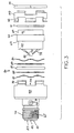
- FIG. 2 is shown a cross-section view of transducer 100 showing ceramic disk 57, which is encased within epoxy casing 64, which is in turn housed in stainless steel housing 33, and showing an embodiment of seal assembly 80 of the present invention.
- FIG. 3 is an exploded side view of transducer 100 of the present invention, showing stainless steel housing 33, seal assembly 80, epoxy casing 64 and retaining cap 66.
- FIG. 4 is an enlarged view of seal assembly 80 of Fig. 2, and shows the multiplicity of annularly shaped members of seal assembly 80, including O-ring seal member 81, backing members 84, and wavy washers 85, all retained within seal bore 82, and further showing a passage 88 formed between bottom face 75 of epoxy casing 64, and upper face 78 of steel casing 33.
- FIG. 5 is an illustration showing epoxy housing 64 with seal assembly surface 60 and shoulder 63, surface 92 and elastomeric spring seat shoulder 93, bottom surface 75, and electrical connectors 48.
- FIG. 6 is a cross-sectional view of receiver 300 having a seal assembly 80 of the present invention.
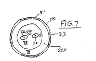
- FIG. 7 is a top view of steel casing 33, showing recess 22, receiving surface 78, and electrical connectors 72 for connection with electrical connectors 48.
- FIG. 1 there is shown a cross-sectional view through well tool 10 showing a side-view of transducer 100 positioned within well tool 10.
- Tool 10 is shown in partial view, with center line 11 and tool body 12 having collar 13, electronics sub 14, and electronics sub connector 271.
- Passage 15 traverses the center of the tool carrying drilling mud.
- Transducer 100 is positioned within recess 22 of collar 13.
- Recess 22 is shaped substantially similar to transducer, only slightly larger than transducer 100, thus forming annular passage 21 between them.
- o-ring 41 Positioned to seal passage 21 is o-ring 41 (shown in later FIGs.), which serves to separate the mud within passage 15 from the mud in the well bore.
- Transducer electrical leads 47 engage electronics sub connector 17 and is thus connected to the electronics of tool 10.
- the electronics sub 14 is physically isolated from fluid in passage 15, and carries the electronics associated with tool 10.
- Wellbore mud is kept out the electronics sub 14 by O-ring 39 (shown in later FIGs.).
- this connection between electrical leads 47 and connector 17 is made in an air environment, isolated from both the fluid in passage 15 and the wellbore fluids.
- transducer 100 showing ceramic disk 57, which is encased within epoxy casing 64, which is in turn housed in stainless steel housing 33, and showing seal assembly 80 of the present invention.
- the ceramic disk 57 is fabricated of material characterized by low sonic impedance and high internal damping. Lead metaniobate ceramic polarized over its entire surface is preferred. When an electrical voltage is applied across its outer and inner flat surfaces, the thickness of the ceramic disk changes slightly. When the impressed voltage is removed, the ceramic disk returns to its original thickness. If the ceramic disk has an oscillating voltage of a certain time length, here called a pulse, the ceramic disk oscillates. An acoustic pulse is emitted from the disk because of the oscillating thickness of the ceramic disk changes in response to the oscillating voltage.
- a pulse-echo sensor or transceiver i.e., the ceramic disk 57, is used to emit an acoustic pulse and receive an echo of the emitted pulse and produce an electrical signal in response thereto.
- the backing member 59 preferably has a sonic impedance approximately the same as the material of the ceramic disk 57. Accordingly, little acoustic energy is reflected back toward the ceramic disk 57 as it meets the interface between ceramic disk 57 and backing member 59.
- the backing member 59 should have high sonic attenuation so that energy into the backing is quickly attenuated as it travels backward into the backing element and bounces from its extremities. It is important that the backing element be fabricated of a material which maintains its properties of high acoustic attenuation and ceramic matching impedance under conditions of high pressure and high temperature.
- Materials suitable for backing member 59 includes rubber blended with tungsten powder.
- Epoxy casing 64 encloses a sensor stack comprising piezoelectric element 57 and backing 59, which cooperate to generate or emit an ultra-sonic pulse or to receive sonic echo pulses. Being enclosed in epoxy, casing 64 isolates the sensor stack from high pressure drilling fluid in the borehole. Such fluid isolation avoids electrical shorting and corrosion of the sensor stack.
- This epoxy casing 64 is mounted within metal cup 33, where it is held in place by retaining cap 66 and retaining ring 35, which is positioned within retaining ring slot 36 running along on both cup 33 and cap 66.
- o-ring 41 Positioned to seal passage 21 (as shown in FIG. 1) is o-ring 41 placed within o-ring seat 45 in casing 33, which serves to separate the mud within passage 15 from the mud in the well bore.
- Wellbore mud is kept out the electronics sub 14 (as shown in FIG. 1) by O-ring 39 positioned within seat 43.
- Threads 70 are utilized to keep transducer 100 attached to electronics sub 14.
- Set screws 67 are utilized to assist in locating contacts within the housing.
- transducer 100 of the present invention showing stainless steel housing 33, seal assembly 80, epoxy casing 64 and retaining cap 66.
- annular members of seal assembly 80 are placed onto seal surface 60 of epoxy member 64, where they will abut against shoulder 63 of epoxy member 64.
- Annularly shaped elastomeric spring member 91 is placed onto surface 92 of epoxy member 64, where it will abut against shoulder 93.
- the epoxy member 64 having seal assembly 80 and spring member 91 inserted thereon, is then inserted into steel casing 33 with the epoxy casing contacts 48 engaged with electrical module 72.
- Retaining cap 66 is then interlocked with steel casing 33.
- Elastomeric spring member 91 prevents retaining cap 66 from contacting epoxy housing 64.
- retaining cap 66 and steel casing 33 are compressed together sufficiently to deform elastomeric spring member 91 and allow for insertion of annularly shaped split retaining ring 35 into grooves 36.
- Seal assembly 80 includes a multiplicity of annularly shaped members, including o-ring seal member 81, backing members 84, and wavy washers 85, all retained within seal bore 82.
- a passage 88 is formed between bottom face 75 of epoxy casing 64, and upper face 78 of steel casing 33. This passage 88 is essentially comprised of fluid passage grooves 74, although there may be some clearance between faces 75 and 78.
- Seal bore 82 serves to transmit pressure between passage 88 and the well bore. Seal assembly 80 forms a barrier to fluids between passage 88 and the well bore.
- Passage 88 is normally filled with a compressible fluid, generally an oil. This compressible liquid is placed into passage 88 utilizing port 51, which is in liquid communication with passage 88 via passage 31. Care must be taken to remove substantially all air from within passage 88 prior to operation and use of transducer 100. Oil is retained in passage 88 utilizing sealing screw 53 and o-ring seal 55.
- Passage 88 will be described in more detail by referring additionally to FIG. 5 and FIG. 7.
- FIG. 5 is an illustration showing epoxy housing 64 with seal assembly surface 60 and shoulder 63, surface 92 and elastomeric spring seat 93, bottom surface 75, fluid passages 74 and electrical connectors 48.
- FIG. 7 is a top view of steel casing 33, showing recess 220 for receiving epoxy housing 64, receiving surface 78, and feed through 72 for connection with electrical connectors 48.
- Receiving surface 78 and bottom surface 75 are mating surfaces, which will abut or nearly abut once epoxy housing 64 is placed within recess 220 and thus form fluid passage.
- Fluid passages 74 are provided in the event that receiving surface 78 and bottom surface 75 are in substantial abutment, to provide for flow of the compressible fluid.
- passage 88 is completely isolated from direct fluid contact with the well environment, with the compressible fluid retained within passage 88 by the seal assembly 80 and o-ring seal 77 placed annularly around each feed though 72.
- Seal assembly is in pressure contact with the well bore, and serves to equalize the pressure within transducer 100 with the pressure of the well bore fluid.
- the wavy washers 85 allow for some compression within seal assembly 80.
- seal assembly 80 will also tend to move between ends 98A and 98B as the pressure dictates. This movement between first position 98A and second position 98B translates the pressure between the well bore and the compressible fluid within passage 88.
- first position 98A and second position 98B translates the pressure between the well bore and the compressible fluid within passage 88.
- the annular members of seal assembly 80 will tend to move away from the well bore and thus increase the liquid pressure within passage 88.
- the annular members of seal assembly 80 will tend to move toward the well bore, and thus decrease the liquid pressure within passage 88.
- FIG. 6 shows a cross-sectional view of piezoelectric transmitter 300, having a multiplicity of annularly shaped ceramic disk members 357, held together by rod 301 passing though the middle of disk members 357. Electrical connectors 347 and feed throughs 372 complete the connection with the ceramic disks 357.
- Other main features of transmitter 300 include threads 311 for securing transmitter 300 to tool 10, and include o-ring seals 341 and 342, positioned within seal grooves 345 and 346, respectively, which provide a barrier between the well fluids and the interior of electronics sub 14.
- This stack of ceramic members 357 is positioned within steel casing 364. Seal bore 80 is formed between the body of steel casing 364 and extension 366A of cap 366.
- Rod 301 extends from electrical assembly 371 into which it is secured, to cap 366.
- a fastener 303 on rod 301 secures cap 366 to rod 301 and thus to casing 364.
- seal assembly 80 To help stabilize the internal pressure of transmitter 300 and the well bore fluid, seal assembly 80, and compressible liquid passage 388 are provided. Compressible fluid resides in passage 388 which is in pressure connectively with seal assembly 80.
- Seal assembly 80 is as described above for transducer 100, and comprises o-ring seal member 81, backing members 84 and wavy washer 85, all residing in seal bore 82.
- Passage 388 is is normally filled with a compressible fluid, generally an oil. As shown in FIG. 6, passage is formed between casing 364 and the ceramic stack 357. The compressible liquid is placed into passage 388 utilizing port 351, which is in liquid communication with passage 388 via passage 331. Care must be taken to remove substantially all air from within passage 388 prior to operation and use of transmitter 300. Oil is retained in passage 388 utilizing sealing screw 353 and an o-ring seal.
- a compressible fluid generally an oil.
- passage 388 is completely isolated from direct fluid contact with the well environment, with the compressible fluid retained within passage 388 by the seal assembly 80 and o-ring seal 339 placed annularly around electrical assembly 371.
- Seal assembly 80 is in pressure communication with the well bore, and serves to equalize the pressure within receiver 300 with the pressure of the well bore fluid. Again, the wavy washers 85 allow for some compression within seal assembly 80. Additionally, seal assembly 80 will also tend to move between ends 98A and 98B as the pressure dictates. This movement within the confines of seal bore 82 translates the pressure between the well bore and the compressible fluid within passage 388. For example, as the well bore fluid pressure increases and acts upon seal assembly 80 at arrow 302, the annular members of seal assembly 80 will tend to move away from the well bore and thus increase the liquid pressure within passage 388. As the well bore fluid pressure decreases, the annular members of seal assembly 80 will tend to move toward the well bore, and thus decrease the liquid pressure within passage 388.
Landscapes
- Physics & Mathematics (AREA)
- Life Sciences & Earth Sciences (AREA)
- Engineering & Computer Science (AREA)
- Acoustics & Sound (AREA)
- Geology (AREA)
- Environmental & Geological Engineering (AREA)
- Multimedia (AREA)
- Remote Sensing (AREA)
- General Life Sciences & Earth Sciences (AREA)
- General Physics & Mathematics (AREA)
- Geophysics (AREA)
- Measuring Fluid Pressure (AREA)
- Earth Drilling (AREA)
Description
- The present invention relates to a transducer for use in a logging-while-drilling tool ("LWD").
- In general an apparatus for making a downhole acoustic log consists of a transmitter capable of providing acoustical impulses, and at least one receiver responsive to acoustical energy, both mounted on a support for movement through the length of a well bore. The transmitter and receiver are spaced apart by a fixed distance and as the support is moved through the well bore, the energy from the acoustic pulses periodically generated by the transmitter is picked up at the receiver after transmission through the well bore. The amplitudes of the received signals are correlated with the depth in the well bore to provide a log indicating the qualities of the cement bonding to the bore over the length of the well.
- The acoustic transmitter and receivers employed for these purposes usually comprise a piezoelectric or magnetostrictive element which, in the case of a transmitter, is actuated by an electrical impulse to generate an acoustic wave and which, in the case of the receiver, is responsive to acoustical energy impinging thereon to generate an electrical impulse to generate an acoustic wave and which, in the case of the receiver, is responsive to acoustical energy impinging thereon to generate an electrical signal generally proportional to the intensity of the acoustic energy.
- For effective operation of these components, it is necessary that they be both efficiently coupled to the surrounding media and at the same time carefully protected from the deleterious effects of the liquids and gases present in well bores or casing.
- These requirements present problems, especially in view of the temperature and pressure variations encountered as the apparatus is moved through different levels in the well bore. The apparatus must not only be impervious to the well pressures, but must also avoid affecting the acoustic properties.
- Flexible elastomer covers have been utilized to enclose transducer elements in an oil. While these covers are liquid tight, they have not prevented gases in the borehole fluid from permeating under high pressures encountered and dissolving in the oil. As a result, when the logging tool was withdrawn from the wellbore, the gases could not escape quickly enough and the cover was often bursting open. Moreover, earlier types of logging tools were difficult to repair by virtue of the technique employed to seal them against well fluids and to equalize them against well fluids and to equalize interior and exterior pressures.
- U.S. Patent no. 3,213,415 discloses a pressure equalizing arrangement for acoustic logging, in which the well tool includes a central supporting mandrel around which the transducer element is mounted to provide an annular cavity therebetween. The cavity is completely filled with an electrically non-conductive liquid such as silicone oil which is also relatively compressible. For effective operation of the transducer element, it is necessary that the pressure in the transducer cavity be equalized with the pressure of the wellbore fluids. Bellows means are provided in communication with both the wellbore fluids and the oil-filled cavity, such that the external pressures are communicated to the oil in the cavity, thereby maintaining both the internal and external pressures substantially equal.
- This type of pressure equalizing arrangement of utilizing an oil filled cavity in the tool into which each of the transducers are positioned is currently still in use.
- One of the major drawbacks of such a system is the maintenance problems. Specifically, removal of any of the transducers, for example for servicing or repair, causes some of the oil to leak from the system, and as such draws air into the oil system. As a hydraulic system, this oil must then be "bled" from the system, and the unit refilled with fresh oil. The operation of bleeding air from the oil system and refilling, can easily consume three, four or more hours.
- Thus, there is a need in the art for an improved system for equalizing pressure between the wellbore fluids and the transducer cavity.
- We have now devised a transducer whereby the disadvantages of prior art arrangements are reduced or overcome.
- According to the present invention, there is provided a transducer comprising:
- (a) a casing having a recess, and having electrical contacts on an outer part of the casing extending through to the recess;
- (b) a piezoelectric housing comprising at least one piezoelectric member therein, and comprising electrical contacts on an outer part of the housing extending through to the piezoelectric member, wherein the housing is within the recess and a closed annular space is defined in part between the housing and the casing, and wherein the housing and casing electrical contacts are connectibly engaged;
- (c) a compressible liquid within the closed annular space, the closed annular space being substantially air-free; and
- (d) wherein the closed annular space is further defined by an annularly shaped seal assembly for retaining the compressible liquid within the closed annular space, and wherein the piezoelectric housing is slidably mounted within the recess for movement between first and second positions in response to a difference in pressure between the closed annular space and the exterior thereof, the movement tending to substantially equalize the pressure there between.
-
- Preferably, the transducer further comprises a backing member disposed in the piezoelectric housing between the piezoelectric member and the electrical contacts The backing member preferably has a sonic impedance substantially the same as the sonic impedance of the piezoelectric member.
- The seal assembly preferably includes an O-ring seal. The seal assembly can include at least one compressible washer, preferably a compressible washer disposed on each side of the O-ring seal, and an annular backing member for the O-ring seal disposed on each side of the O-ring seal, between each washer and the O-ring seal.
- The transducer of the invention can include stop means to prevent movement of the seal assembly beyond the first and second positions. The stop means can, for example, comprises a shoulder provided on the casing and/or on the housing.
- In order that the invention may be more fully understood, embodiments thereof will now be described, by way of example only, with reference to the accompanying drawings, wherein:
- FIG. 1 is a cross-sectional view through
well tool 10 showing a side-view of one embodiment oftransducer 100 of the invention, positioned withinrecess 22 ofwell tool 10, withtool 10 havingcollar 13,electronics sub 14, and electronics sub connector 17. - FIG. 2 is shown a cross-section view of
transducer 100 showing ceramic disk 57, which is encased withinepoxy casing 64, which is in turn housed instainless steel housing 33, and showing an embodiment ofseal assembly 80 of the present invention. - FIG. 3 is an exploded side view of
transducer 100 of the present invention, showingstainless steel housing 33,seal assembly 80,epoxy casing 64 and retainingcap 66. - FIG. 4 is an enlarged view of
seal assembly 80 of Fig. 2, and shows the multiplicity of annularly shaped members ofseal assembly 80, including O-ring seal member 81,backing members 84, andwavy washers 85, all retained withinseal bore 82, and further showing apassage 88 formed betweenbottom face 75 ofepoxy casing 64, andupper face 78 ofsteel casing 33. - FIG. 5 is an illustration showing
epoxy housing 64 withseal assembly surface 60 andshoulder 63,surface 92 and elastomericspring seat shoulder 93,bottom surface 75, andelectrical connectors 48. - FIG. 6 is a cross-sectional view of
receiver 300 having aseal assembly 80 of the present invention. - FIG. 7 is a top view of
steel casing 33, showingrecess 22, receivingsurface 78, andelectrical connectors 72 for connection withelectrical connectors 48. - The present invention is best understood by reference to FIGs. 1 through 7. Referring first to FIG. 1 there is shown a cross-sectional view through
well tool 10 showing a side-view oftransducer 100 positioned withinwell tool 10.Tool 10 is shown in partial view, with center line 11 and tool body 12 havingcollar 13,electronics sub 14, and electronics sub connector 271. - Passage 15 traverses the center of the tool carrying drilling mud.
Transducer 100 is positioned withinrecess 22 ofcollar 13.Recess 22 is shaped substantially similar to transducer, only slightly larger thantransducer 100, thus formingannular passage 21 between them. Positioned toseal passage 21 is o-ring 41 (shown in later FIGs.), which serves to separate the mud withinpassage 15 from the mud in the well bore. - Transducer
electrical leads 47 engage electronics sub connector 17 and is thus connected to the electronics oftool 10. Theelectronics sub 14 is physically isolated from fluid inpassage 15, and carries the electronics associated withtool 10. Wellbore mud is kept out theelectronics sub 14 by O-ring 39 (shown in later FIGs.). Thus, this connection betweenelectrical leads 47 and connector 17 is made in an air environment, isolated from both the fluid inpassage 15 and the wellbore fluids. - Referring additionally to FIG. 2, there is shown a cross-sectional view of
transducer 100 showing ceramic disk 57, which is encased withinepoxy casing 64, which is in turn housed instainless steel housing 33, and showingseal assembly 80 of the present invention. - The ceramic disk 57 is fabricated of material characterized by low sonic impedance and high internal damping. Lead metaniobate ceramic polarized over its entire surface is preferred. When an electrical voltage is applied across its outer and inner flat surfaces, the thickness of the ceramic disk changes slightly. When the impressed voltage is removed, the ceramic disk returns to its original thickness. If the ceramic disk has an oscillating voltage of a certain time length, here called a pulse, the ceramic disk oscillates. An acoustic pulse is emitted from the disk because of the oscillating thickness of the ceramic disk changes in response to the oscillating voltage.
- With no voltage on the disk, it serves as a receiver. In a pulse-echo sensor or transceiver, i.e., the ceramic disk 57, is used to emit an acoustic pulse and receive an echo of the emitted pulse and produce an electrical signal in response thereto.
- The backing member 59 preferably has a sonic impedance approximately the same as the material of the ceramic disk 57. Accordingly, little acoustic energy is reflected back toward the ceramic disk 57 as it meets the interface between ceramic disk 57 and backing member 59. On the other hand, the backing member 59 should have high sonic attenuation so that energy into the backing is quickly attenuated as it travels backward into the backing element and bounces from its extremities. It is important that the backing element be fabricated of a material which maintains its properties of high acoustic attenuation and ceramic matching impedance under conditions of high pressure and high temperature. Materials suitable for backing member 59 includes rubber blended with tungsten powder.
-
Epoxy casing 64 encloses a sensor stack comprising piezoelectric element 57 and backing 59, which cooperate to generate or emit an ultra-sonic pulse or to receive sonic echo pulses. Being enclosed in epoxy, casing 64 isolates the sensor stack from high pressure drilling fluid in the borehole. Such fluid isolation avoids electrical shorting and corrosion of the sensor stack. - This
epoxy casing 64 is mounted withinmetal cup 33, where it is held in place by retainingcap 66 and retainingring 35, which is positioned within retainingring slot 36 running along on bothcup 33 andcap 66. - Electrical connections are made between ceramic member 57,
wires 62,epoxy casing contacts 48, feed through 72, and spring loadedelectrical contactors 47 incontact block 52, all of which are well known in the art. An o-ring 77 is utilized around feed through 72 to keep pressure stabilizer fluid inpassage 88 away fromconnectors 47. - Positioned to seal passage 21 (as shown in FIG. 1) is o-
ring 41 placed within o-ring seat 45 incasing 33, which serves to separate the mud withinpassage 15 from the mud in the well bore. Wellbore mud is kept out the electronics sub 14 (as shown in FIG. 1) by O-ring 39 positioned withinseat 43.Threads 70 are utilized to keeptransducer 100 attached to electronics sub 14. Set screws 67 are utilized to assist in locating contacts within the housing. - Referring additionally to FIG 3 there is shown an exploded side view of
transducer 100 of the present invention, showingstainless steel housing 33,seal assembly 80,epoxy casing 64 and retainingcap 66. - In assembly, the annular members of
seal assembly 80 are placed ontoseal surface 60 ofepoxy member 64, where they will abut againstshoulder 63 ofepoxy member 64. Annularly shapedelastomeric spring member 91 is placed ontosurface 92 ofepoxy member 64, where it will abut againstshoulder 93. Theepoxy member 64 havingseal assembly 80 andspring member 91 inserted thereon, is then inserted intosteel casing 33 with theepoxy casing contacts 48 engaged withelectrical module 72. - Retaining
cap 66 is then interlocked withsteel casing 33.Elastomeric spring member 91 prevents retainingcap 66 from contactingepoxy housing 64. Thus, retainingcap 66 andsteel casing 33 are compressed together sufficiently to deformelastomeric spring member 91 and allow for insertion of annularly shaped split retainingring 35 intogrooves 36. - Referring additionally to FIG. 4, there is shown an enlarged view of
seal assembly 80 from FIG. 2.Seal assembly 80 includes a multiplicity of annularly shaped members, including o-ring seal member 81, backingmembers 84, andwavy washers 85, all retained within seal bore 82. Apassage 88 is formed betweenbottom face 75 ofepoxy casing 64, andupper face 78 ofsteel casing 33. Thispassage 88 is essentially comprised offluid passage grooves 74, although there may be some clearance betweenfaces passage 88 and the well bore.Seal assembly 80 forms a barrier to fluids betweenpassage 88 and the well bore. -
Passage 88 is normally filled with a compressible fluid, generally an oil. This compressible liquid is placed intopassage 88 utilizingport 51, which is in liquid communication withpassage 88 via passage 31. Care must be taken to remove substantially all air from withinpassage 88 prior to operation and use oftransducer 100. Oil is retained inpassage 88 utilizing sealingscrew 53 and o-ring seal 55. -
Passage 88 will be described in more detail by referring additionally to FIG. 5 and FIG. 7. - FIG. 5 is an illustration showing
epoxy housing 64 withseal assembly surface 60 andshoulder 63,surface 92 andelastomeric spring seat 93,bottom surface 75,fluid passages 74 andelectrical connectors 48. - FIG. 7 is a top view of
steel casing 33, showingrecess 220 for receivingepoxy housing 64, receivingsurface 78, and feed through 72 for connection withelectrical connectors 48. Receivingsurface 78 andbottom surface 75 are mating surfaces, which will abut or nearly abut onceepoxy housing 64 is placed withinrecess 220 and thus form fluid passage.Fluid passages 74 are provided in the event that receivingsurface 78 andbottom surface 75 are in substantial abutment, to provide for flow of the compressible fluid. - Once
transducer 100 is assembled,passage 88 is completely isolated from direct fluid contact with the well environment, with the compressible fluid retained withinpassage 88 by theseal assembly 80 and o-ring seal 77 placed annularly around each feed though 72. - Seal assembly is in pressure contact with the well bore, and serves to equalize the pressure within
transducer 100 with the pressure of the well bore fluid. Thewavy washers 85 allow for some compression withinseal assembly 80. Additionally,seal assembly 80 will also tend to move between ends 98A and 98B as the pressure dictates. This movement between first position 98A and second position 98B translates the pressure between the well bore and the compressible fluid withinpassage 88. For example, as the well bore fluid pressure increases, the annular members ofseal assembly 80 will tend to move away from the well bore and thus increase the liquid pressure withinpassage 88. As the well bore fluid pressure decreases, the annular members ofseal assembly 80 will tend to move toward the well bore, and thus decrease the liquid pressure withinpassage 88. Thus, with seal assembly slideably positioned within seal bore 80, it is able to stabilize pressure between the interior oftransducer 100 and the well bore fluid. - While the present invention has been illustrated with respect to a
transducer 100, the present invention may also be advantageously applied to a transmitter. Referring now to FIG. 6 there is shown another embodiment of the present invention. FiG. 6 shows a cross-sectional view ofpiezoelectric transmitter 300, having a multiplicity of annularly shapedceramic disk members 357, held together byrod 301 passing though the middle ofdisk members 357.Electrical connectors 347 andfeed throughs 372 complete the connection with theceramic disks 357. Other main features oftransmitter 300 includethreads 311 for securingtransmitter 300 totool 10, and include o-ring seals seal grooves electronics sub 14. - This stack of
ceramic members 357 is positioned withinsteel casing 364. Seal bore 80 is formed between the body ofsteel casing 364 andextension 366A ofcap 366.Rod 301 extends fromelectrical assembly 371 into which it is secured, to cap 366. A fastener 303 onrod 301 securescap 366 torod 301 and thus tocasing 364. - To help stabilize the internal pressure of
transmitter 300 and the well bore fluid,seal assembly 80, and compressibleliquid passage 388 are provided. Compressible fluid resides inpassage 388 which is in pressure connectively withseal assembly 80. -
Seal assembly 80 is as described above fortransducer 100, and comprises o-ring seal member 81, backingmembers 84 andwavy washer 85, all residing in seal bore 82. -
Passage 388 is is normally filled with a compressible fluid, generally an oil. As shown in FIG. 6, passage is formed betweencasing 364 and theceramic stack 357. The compressible liquid is placed intopassage 388 utilizingport 351, which is in liquid communication withpassage 388 viapassage 331. Care must be taken to remove substantially all air from withinpassage 388 prior to operation and use oftransmitter 300. Oil is retained inpassage 388 utilizing sealingscrew 353 and an o-ring seal. - Once
transmitter 300 is assembled,passage 388 is completely isolated from direct fluid contact with the well environment, with the compressible fluid retained withinpassage 388 by theseal assembly 80 and o-ring seal 339 placed annularly aroundelectrical assembly 371. -
Seal assembly 80 is in pressure communication with the well bore, and serves to equalize the pressure withinreceiver 300 with the pressure of the well bore fluid. Again, thewavy washers 85 allow for some compression withinseal assembly 80. Additionally,seal assembly 80 will also tend to move between ends 98A and 98B as the pressure dictates. This movement within the confines of seal bore 82 translates the pressure between the well bore and the compressible fluid withinpassage 388. For example, as the well bore fluid pressure increases and acts uponseal assembly 80 atarrow 302, the annular members ofseal assembly 80 will tend to move away from the well bore and thus increase the liquid pressure withinpassage 388. As the well bore fluid pressure decreases, the annular members ofseal assembly 80 will tend to move toward the well bore, and thus decrease the liquid pressure withinpassage 388. - While the illustrative embodiments of the invention have been described with particularity, it will be understood that various other modifications will be apparent to and can be readily made by those skilled in the art.
Claims (10)
- A transducer (100) comprising:(a) a casing (33) having a recess (220), and having electrical contacts (47) on an outer part of the casing extending through to the recess (220);(b) a piezoelectric housing (64) comprising at least one piezoelectric member (57) therein, and comprising electrical contacts (48) on an outer part of the housing (64) extending through to the piezoelectric member (57), wherein the housing is within the recess (220) and a closed annular space (88) is defined in part between the housing (64) and the casing (33), and wherein the housing and casing electrical contacts (48) are connectibly engaged;(c) a compressible liquid within the closed annular space (88), the closed annular space being substantially air-free; and(d) wherein the closed annular space (88) is further defined by an annularly shaped seal assembly (80) for retaining the compressible liquid within the closed annular space (88), and wherein the piezoelectric housing (64) is slidably mounted within the recess (220) for movement between first and second positions in response to a difference in pressure between the closed annular space (88) and the exterior thereof, the movement tending to substantially equalize the pressure there between.
- A transducer according to claim 1, further comprising a backing member (59) disposed in the piezoelectric housing (64) between the piezoelectric member (58) and the electrical contacts (48).
- A transducer according to claim 2, wherein the backing member (59) has a sonic impedance substantially the same as the sonic impedance of the piezoelectric member (57).
- A transducer according to claim 1,2 or 3, wherein the seal assembly (80) includes an O-ring seal (81).
- A transducer according to any preceding claim, wherein the seal assembly includes a compressible washer (85).
- A transducer according to any one of claims 1 to 4, wherein the seal assembly (80) comprises a compressible washer (85) disposed on each side of the O-ring seal (81), and an annular backing member for the O-ring seal disposed on each side of the O-ring seal (81), between each washer (85) and the O-ring seal (81).
- A transducer according to any preceding claim, further comprising stop means to prevent movement of the seal assembly beyond the first and second positions.
- A transducer according to claim 7, wherein the stop means comprises a shoulder provided on the casing and/or on the housing.
- An acoustic receiver comprising a transducer as defined in any one of the preceding claims.
- An acoustic transmitter comprising a transducer as defined in any one of claims 1 to 8.
Applications Claiming Priority (2)
| Application Number | Priority Date | Filing Date | Title |
|---|---|---|---|
| US08/483,112 US5644186A (en) | 1995-06-07 | 1995-06-07 | Acoustic Transducer for LWD tool |
| US483112 | 1995-06-07 |
Publications (3)
| Publication Number | Publication Date |
|---|---|
| EP0747732A2 EP0747732A2 (en) | 1996-12-11 |
| EP0747732A3 EP0747732A3 (en) | 1998-07-29 |
| EP0747732B1 true EP0747732B1 (en) | 2001-08-22 |
Family
ID=23918708
Family Applications (1)
| Application Number | Title | Priority Date | Filing Date |
|---|---|---|---|
| EP96304306A Expired - Lifetime EP0747732B1 (en) | 1995-06-07 | 1996-06-07 | Transducer for logging-while-drilling tool |
Country Status (3)
| Country | Link |
|---|---|
| US (1) | US5644186A (en) |
| EP (1) | EP0747732B1 (en) |
| NO (1) | NO962373L (en) |
Cited By (1)
| Publication number | Priority date | Publication date | Assignee | Title |
|---|---|---|---|---|
| CN1997916B (en) * | 2004-07-01 | 2010-10-27 | 哈里伯顿能源服务公司 | Acoustic telemetry transceiver |
Families Citing this family (41)
| Publication number | Priority date | Publication date | Assignee | Title |
|---|---|---|---|---|
| US5987385A (en) * | 1997-08-29 | 1999-11-16 | Dresser Industries, Inc. | Method and apparatus for creating an image of an earth borehole or a well casing |
| US6137747A (en) * | 1998-05-29 | 2000-10-24 | Halliburton Energy Services, Inc. | Single point contact acoustic transmitter |
| US6366531B1 (en) | 1998-09-22 | 2002-04-02 | Dresser Industries, Inc. | Method and apparatus for acoustic logging |
| US6564899B1 (en) | 1998-09-24 | 2003-05-20 | Dresser Industries, Inc. | Method and apparatus for absorbing acoustic energy |
| US6213250B1 (en) * | 1998-09-25 | 2001-04-10 | Dresser Industries, Inc. | Transducer for acoustic logging |
| US6429784B1 (en) * | 1999-02-19 | 2002-08-06 | Dresser Industries, Inc. | Casing mounted sensors, actuators and generators |
| US6310426B1 (en) | 1999-07-14 | 2001-10-30 | Halliburton Energy Services, Inc. | High resolution focused ultrasonic transducer, for LWD method of making and using same |
| US6466513B1 (en) | 1999-10-21 | 2002-10-15 | Schlumberger Technology Corporation | Acoustic sensor assembly |
| US6643221B1 (en) | 2001-11-06 | 2003-11-04 | Schlumberger Technology Corporation | Structures and methods for damping tool waves particularly for acoustic logging tools |
| US7036363B2 (en) * | 2003-07-03 | 2006-05-02 | Pathfinder Energy Services, Inc. | Acoustic sensor for downhole measurement tool |
| US7513147B2 (en) * | 2003-07-03 | 2009-04-07 | Pathfinder Energy Services, Inc. | Piezocomposite transducer for a downhole measurement tool |
| US7075215B2 (en) * | 2003-07-03 | 2006-07-11 | Pathfinder Energy Services, Inc. | Matching layer assembly for a downhole acoustic sensor |
| US6995500B2 (en) * | 2003-07-03 | 2006-02-07 | Pathfinder Energy Services, Inc. | Composite backing layer for a downhole acoustic sensor |
| US7364007B2 (en) * | 2004-01-08 | 2008-04-29 | Schlumberger Technology Corporation | Integrated acoustic transducer assembly |
| US7997380B2 (en) * | 2004-06-22 | 2011-08-16 | Halliburton Energy Services, Inc. | Low frequency acoustic attenuator |
| US8544564B2 (en) | 2005-04-05 | 2013-10-01 | Halliburton Energy Services, Inc. | Wireless communications in a drilling operations environment |
| US8107316B2 (en) * | 2005-03-18 | 2012-01-31 | Halliburton Energy Services, Inc. | Controlled source imbalance apparatus, systems, and methods |
| US8256565B2 (en) * | 2005-05-10 | 2012-09-04 | Schlumberger Technology Corporation | Enclosures for containing transducers and electronics on a downhole tool |
| US7464588B2 (en) * | 2005-10-14 | 2008-12-16 | Baker Hughes Incorporated | Apparatus and method for detecting fluid entering a wellbore |
| US7587936B2 (en) * | 2007-02-01 | 2009-09-15 | Smith International Inc. | Apparatus and method for determining drilling fluid acoustic properties |
| US8279713B2 (en) * | 2007-07-20 | 2012-10-02 | Precision Energy Services, Inc. | Acoustic transmitter comprising a plurality of piezoelectric plates |
| US7864629B2 (en) * | 2007-11-20 | 2011-01-04 | Precision Energy Services, Inc. | Monopole acoustic transmitter comprising a plurality of piezoelectric discs |
| US8286475B2 (en) * | 2008-07-04 | 2012-10-16 | Schlumberger Technology Corporation | Transducer assemblies for downhole tools |
| US20100020638A1 (en) * | 2008-07-24 | 2010-01-28 | Precision Energy Services, Inc. | Monopole acoustic transmitter ring comprising piezoelectric material |
| US8117907B2 (en) * | 2008-12-19 | 2012-02-21 | Pathfinder Energy Services, Inc. | Caliper logging using circumferentially spaced and/or angled transducer elements |
| WO2010112042A1 (en) * | 2009-04-02 | 2010-10-07 | Statoil Asa | Apparatus and method for evaluating a wellbore, in particular a casing thereof |
| CN102346172A (en) * | 2010-07-30 | 2012-02-08 | 广州多浦乐电子科技有限公司 | Back lining material for ultrasonic non-destructive detector probe and manufacture method thereof |
| US9079221B2 (en) | 2011-02-15 | 2015-07-14 | Halliburton Energy Services, Inc. | Acoustic transducer with impedance matching layer |
| SG193540A1 (en) * | 2011-03-23 | 2013-10-30 | Halliburton Energy Serv Inc | Ultrasound transducer with acoustic isolator and corresponding mounting method |
| WO2013036770A1 (en) * | 2011-09-09 | 2013-03-14 | Knowles Electronics, Llc | Rf shielding for acoustic devices |
| US10196862B2 (en) | 2013-09-27 | 2019-02-05 | Cold Bore Technology Inc. | Methods and apparatus for operatively mounting actuators to pipe |
| US10101483B2 (en) * | 2013-12-19 | 2018-10-16 | Schlumberger Technology Corporation | Vibration control for a cement evaluation tool |
| US9389329B2 (en) * | 2014-03-31 | 2016-07-12 | Baker Hughes Incorporated | Acoustic source with piezoelectric actuator array and stroke amplification for broad frequency range acoustic output |
| EP2940246A1 (en) * | 2014-05-02 | 2015-11-04 | Piezotech, LLC | Pressure-compensated transducer assembly |
| US20160138948A1 (en) * | 2014-11-18 | 2016-05-19 | AK Research LLC | Downhole oil well sensor housing having a compression seal assembly |
| US10670762B2 (en) | 2015-07-02 | 2020-06-02 | Halliburton Energy Services, Inc. | Pressure balanced transducer assembly and measurement tool |
| US10481288B2 (en) * | 2015-10-02 | 2019-11-19 | Halliburton Energy Services, Inc. | Ultrasonic transducer with improved backing element |
| CN107762491B (en) * | 2016-08-17 | 2020-09-25 | 中国石油化工股份有限公司 | While-drilling acoustic logging radiation device |
| US10539435B2 (en) | 2017-05-17 | 2020-01-21 | General Electric Company | Pressure compensated sensors |
| US11029177B2 (en) * | 2017-05-17 | 2021-06-08 | Baker Hughes Holdings Llc | Pressure compensated sensors |
| US11649717B2 (en) | 2018-09-17 | 2023-05-16 | Saudi Arabian Oil Company | Systems and methods for sensing downhole cement sheath parameters |
Family Cites Families (12)
| Publication number | Priority date | Publication date | Assignee | Title |
|---|---|---|---|---|
| DE334055C (en) * | 1917-08-28 | 1921-03-12 | Signal Ges M B H | Equipment for the protection of sound devices against impermissible stresses due to pressure surges |
| US3213415A (en) * | 1962-08-27 | 1965-10-19 | Schlumberger Well Surv Corp | Pressure equalizing arrangement for acoustic logging |
| US4069433A (en) * | 1976-06-03 | 1978-01-17 | Westinghouse Electric Corporation | Modular transducer assembly |
| US4450540A (en) * | 1980-03-13 | 1984-05-22 | Halliburton Company | Swept energy source acoustic logging system |
| US4493062A (en) * | 1983-12-12 | 1985-01-08 | Halliburton Company | Resonant frequency modification of piezoelectric transducers |
| US4928031A (en) * | 1986-11-25 | 1990-05-22 | Western Atlas International, Inc. | Pressure/temperature compensated transducer pad assembly |
| US4976259A (en) * | 1986-12-22 | 1990-12-11 | Mountain Medical Equipment, Inc. | Ultrasonic nebulizer |
| US5146050A (en) * | 1989-04-25 | 1992-09-08 | Western Atlas International, Inc. | Method and apparatus for acoustic formation dip logging |
| US5130950A (en) * | 1990-05-16 | 1992-07-14 | Schlumberger Technology Corporation | Ultrasonic measurement apparatus |
| US5319965A (en) * | 1992-03-02 | 1994-06-14 | Halliburton Company | Multiple channel pressure recorder |
| US5389848A (en) * | 1993-01-15 | 1995-02-14 | General Electric Company | Hybrid ultrasonic transducer |
| US5438170A (en) * | 1994-04-28 | 1995-08-01 | Klaveness; Alf | Borehole seismic pulse generator and system |
-
1995
- 1995-06-07 US US08/483,112 patent/US5644186A/en not_active Expired - Lifetime
-
1996
- 1996-06-06 NO NO962373A patent/NO962373L/en not_active Application Discontinuation
- 1996-06-07 EP EP96304306A patent/EP0747732B1/en not_active Expired - Lifetime
Cited By (1)
| Publication number | Priority date | Publication date | Assignee | Title |
|---|---|---|---|---|
| CN1997916B (en) * | 2004-07-01 | 2010-10-27 | 哈里伯顿能源服务公司 | Acoustic telemetry transceiver |
Also Published As
| Publication number | Publication date |
|---|---|
| EP0747732A3 (en) | 1998-07-29 |
| NO962373D0 (en) | 1996-06-06 |
| EP0747732A2 (en) | 1996-12-11 |
| US5644186A (en) | 1997-07-01 |
| NO962373L (en) | 1996-12-09 |
Similar Documents
| Publication | Publication Date | Title |
|---|---|---|
| EP0747732B1 (en) | Transducer for logging-while-drilling tool | |
| US3970878A (en) | Piezoelectric transducer unit and hydrophone assembly | |
| US6213250B1 (en) | Transducer for acoustic logging | |
| CA2545921C (en) | Enclosures for containing transducers and electronics on a downhole tool | |
| CA2138907C (en) | Transmitter for sonic logging while drilling | |
| US6466513B1 (en) | Acoustic sensor assembly | |
| US5063542A (en) | Piezoelectric transducer with displacement amplifier | |
| US7913806B2 (en) | Enclosures for containing transducers and electronics on a downhole tool | |
| US5033032A (en) | Air-gap hydrophone | |
| US5703836A (en) | Acoustic transducer | |
| US20110222369A1 (en) | Acoustic Transducer with a Liquid-Filled Porous Medium Backing and Methods of Making and Using Same | |
| US3051927A (en) | Transducer assemblies | |
| US6418792B1 (en) | Pressure compensated transducer | |
| EP2606378B1 (en) | Ultrasound transducer with acoustic isolator and corresponding mounting method | |
| CN114026467B (en) | Detection system for detecting anomalies in discontinuous interfaces and/or pore pressure in geological formations | |
| WO2022016959A1 (en) | Sensor module, sensor assembly and acoustic logging tool | |
| US5218576A (en) | Underwater transducer | |
| US3385369A (en) | Pressure-equalizing apparatus for well tools | |
| US4156228A (en) | Acoustic transducer with acoustic isolating mounting base | |
| US9063242B2 (en) | Acoustic transducers with dynamic frequency range | |
| CA2911106A1 (en) | High frequency inspection of downhole environment | |
| OA20888A (en) | Detection system for detecting discontinuity interfaces and/or anomalies in pore pressures in geological formations. | |
| SU542965A1 (en) | A device for recording pressure pulses | |
| WO2020251557A1 (en) | Ringdown controlled downhole transducer | |
| MXPA06005131A (en) | Enclosures for containing transducers and electronics on a downhole tool |
Legal Events
| Date | Code | Title | Description |
|---|---|---|---|
| PUAI | Public reference made under article 153(3) epc to a published international application that has entered the european phase |
Free format text: ORIGINAL CODE: 0009012 |
|
| AK | Designated contracting states |
Kind code of ref document: A2 Designated state(s): FR GB NL |
|
| PUAL | Search report despatched |
Free format text: ORIGINAL CODE: 0009013 |
|
| AK | Designated contracting states |
Kind code of ref document: A3 Designated state(s): FR GB NL |
|
| 17P | Request for examination filed |
Effective date: 19980825 |
|
| GRAG | Despatch of communication of intention to grant |
Free format text: ORIGINAL CODE: EPIDOS AGRA |
|
| 17Q | First examination report despatched |
Effective date: 20000823 |
|
| GRAG | Despatch of communication of intention to grant |
Free format text: ORIGINAL CODE: EPIDOS AGRA |
|
| GRAH | Despatch of communication of intention to grant a patent |
Free format text: ORIGINAL CODE: EPIDOS IGRA |
|
| RAP1 | Party data changed (applicant data changed or rights of an application transferred) |
Owner name: HALLIBURTON ENERGY SERVICES, INC. |
|
| GRAH | Despatch of communication of intention to grant a patent |
Free format text: ORIGINAL CODE: EPIDOS IGRA |
|
| GRAA | (expected) grant |
Free format text: ORIGINAL CODE: 0009210 |
|
| AK | Designated contracting states |
Kind code of ref document: B1 Designated state(s): FR GB NL |
|
| ET | Fr: translation filed | ||
| REG | Reference to a national code |
Ref country code: GB Ref legal event code: IF02 |
|
| PLBE | No opposition filed within time limit |
Free format text: ORIGINAL CODE: 0009261 |
|
| STAA | Information on the status of an ep patent application or granted ep patent |
Free format text: STATUS: NO OPPOSITION FILED WITHIN TIME LIMIT |
|
| 26N | No opposition filed | ||
| PG25 | Lapsed in a contracting state [announced via postgrant information from national office to epo] |
Ref country code: NL Free format text: LAPSE BECAUSE OF NON-PAYMENT OF DUE FEES Effective date: 20030101 |
|
| REG | Reference to a national code |
Ref country code: GB Ref legal event code: 732E |
|
| PG25 | Lapsed in a contracting state [announced via postgrant information from national office to epo] |
Ref country code: FR Free format text: LAPSE BECAUSE OF NON-PAYMENT OF DUE FEES Effective date: 20030228 |
|
| NLV4 | Nl: lapsed or anulled due to non-payment of the annual fee |
Effective date: 20030101 |
|
| REG | Reference to a national code |
Ref country code: FR Ref legal event code: ST |
|
| PGFP | Annual fee paid to national office [announced via postgrant information from national office to epo] |
Ref country code: GB Payment date: 20040602 Year of fee payment: 9 |
|
| PG25 | Lapsed in a contracting state [announced via postgrant information from national office to epo] |
Ref country code: GB Free format text: LAPSE BECAUSE OF NON-PAYMENT OF DUE FEES Effective date: 20050607 |
|
| GBPC | Gb: european patent ceased through non-payment of renewal fee |
Effective date: 20050607 |