EP0746132A2 - Paging system for a cordless telephone - Google Patents
Paging system for a cordless telephone Download PDFInfo
- Publication number
- EP0746132A2 EP0746132A2 EP96303890A EP96303890A EP0746132A2 EP 0746132 A2 EP0746132 A2 EP 0746132A2 EP 96303890 A EP96303890 A EP 96303890A EP 96303890 A EP96303890 A EP 96303890A EP 0746132 A2 EP0746132 A2 EP 0746132A2
- Authority
- EP
- European Patent Office
- Prior art keywords
- paging
- cordless telephone
- unit
- signal
- pager
- Prior art date
- Legal status (The legal status is an assumption and is not a legal conclusion. Google has not performed a legal analysis and makes no representation as to the accuracy of the status listed.)
- Withdrawn
Links
- 238000004891 communication Methods 0.000 description 9
- 230000008054 signal transmission Effects 0.000 description 9
- 238000010586 diagram Methods 0.000 description 6
- 230000006870 function Effects 0.000 description 6
- 230000005540 biological transmission Effects 0.000 description 4
- 230000000994 depressogenic effect Effects 0.000 description 2
- 238000010295 mobile communication Methods 0.000 description 1
Images


Classifications
-
- H—ELECTRICITY
- H04—ELECTRIC COMMUNICATION TECHNIQUE
- H04B—TRANSMISSION
- H04B5/00—Near-field transmission systems, e.g. inductive loop type
-
- H—ELECTRICITY
- H04—ELECTRIC COMMUNICATION TECHNIQUE
- H04W—WIRELESS COMMUNICATION NETWORKS
- H04W84/00—Network topologies
- H04W84/02—Hierarchically pre-organised networks, e.g. paging networks, cellular networks, WLAN [Wireless Local Area Network] or WLL [Wireless Local Loop]
- H04W84/022—One-way selective calling networks, e.g. wide area paging
-
- H—ELECTRICITY
- H04—ELECTRIC COMMUNICATION TECHNIQUE
- H04M—TELEPHONIC COMMUNICATION
- H04M1/00—Substation equipment, e.g. for use by subscribers
- H04M1/72—Mobile telephones; Cordless telephones, i.e. devices for establishing wireless links to base stations without route selection
- H04M1/725—Cordless telephones
- H04M1/72502—Cordless telephones with one base station connected to a single line
- H04M1/72505—Radio link set-up procedures
Definitions
- the present invention relates to a radio selective calling receiver and a cordless telephone system. Broadly, it provides a radio selective calling receiver adapted to be called through a general public telephone line from a cordless telephone without using the public telephone line, and a cordless telephone system.
- a cordless telephone system comprises a master unit and one or more subsidiary units.
- the master unit can call the subsidiary unit, or a subsidiary unit can call another subsidiary unit.
- the radio selective calling receiver the general public telephone line must be used to call the carrier of the receiver. Therefore, even when the person to be called is present near the caller, the caller is charged for every calling operation.
- the person to be called always carries a subsidiary unit of the cordless telephone system
- the user can call this person without being charged for the call as far as this person is within the area covered by the cordless telephone system.
- the subsidiary unit is larger in both size and weight than the radio selective calling receiver, e.g., weighs several hundred grams, resulting in poor portability.
- the present invention has been made in consideration of the above situation, and aims to provide a compact and lightweight highly portable paging system in which a user need not be charged for a call from a person near the user.
- a paging system comprising a radio selective calling receiver which can be directly called from a cordless telephone master unit or a subsidiary unit by using a frequency band for a paging terminal without using a telephone line, and a cordless telephone capable of transmitting a signal to the receiver.
- a cordless selective call number for each radio selective calling receiver is transmitted in accordance with a prescribed signal format. With this operation, as in the normal calling operation of the radio selective calling receiver, the selective call number and a message signal can be received.
- the user can call the radio selective calling receiver near a room or house within the range of several hundred meters from the cordless telephone master or subsidiary unit without using the general public telephone line. Therefore, a person who always carries the light-weighted radio selective calling receiver can be called even outside the house as usual. When the carrier is near the house, the user can always call that person without being charged for the call.
- Fig. 1 is a view showing a general configuration of a cordless telephone and paging terminals.
- a cordless telephone master unit 1 has a normal function of speech communication using a general public telephone line and a function of speech communication with a cordless telephone subsidiary unit.
- Cordless telephone subsidiary units 2a and 2b have a function of speech communication using the general telephone line through the master unit, the function of speech communication with the master unit, and an inter-subsidiary-unit speech communication function.
- Pagers (radio selective calling receivers) 3a to 3c can be called through the general public telephone line.
- Reference numeral 4 denotes a house.
- a selective call number for the general public telephone line is identified on the basis of a radio signal transmitted from a paging system base station 5 through the normal telephone line, and a tone-only signal or a signal including a message is received.
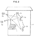
- Fig. 2 is a view showing an example of the configuration of the present invention.
- a transmission function which allows transmission of the selective call number for the cordless telephone by using a frequency corresponding to the receiver in accordance with a transmission protocol corresponding to the paging terminal is arranged in the master unit 1 and the subsidiary units 2a and 2b.
- the selective call number registered in the corresponding one of the pagers 3a to 3c and an arbitrary message signal (unnecessary for a tone-only signal) are transmitted.
- the pager 3a, 3b, or 3c near the house 4 can be called without using the general telephone line.
- Fig. 3 is a block diagram showing an example of the internal arrangement of a cordless telephone master unit of the present invention.
- a master unit 100 comprises an antenna 101 for transmitting/receiving a radio signal to/from a cordless telephone subsidiary unit 200 shown in Fig. 4, a cordless telephone radio unit 112 for modulating/demodulating the radio signal transmitted/received to/from the cordless telephone subsidiary unit 200, an antenna 102 for transmitting a selective call signal to a pager 300 shown in Fig.
- a pager signal transmission unit 103 for modulating the selective call signal to be transmitted to the pager 300 a control unit 104 for controlling pager call processing, an LCD driver 105 for controlling display on an LCD 106, the LCD 106 for displaying various information including a telephone number, a memory 107 for temporarily storing the selective call signal to be transmitted, and the like, a cordless ID-ROM 108 storing the selective call number used to call the pager 300 from the master unit 100, a speech input/output driver 109 for controlling a loudspeaker 110 and a microphone 111, the loudspeaker 110 arranged at the receiver of the master unit 100 to perform speech communication, the microphone 111 arranged at the transmitter of the master unit 100 to perform speech communication, a public line connection interface unit 113 for connecting the master unit 100 to a public telephone line, and a pager calling switch 114 depressed when the user calls the pager 300 from the master unit 100.
- Fig. 4 is a block diagram showing an example of the internal arrangement of the cordless telephone subsidiary unit of the present invention.
- the subsidiary unit 200 comprises an antenna 201 for transmitting/receiving a radio signal to/from the cordless telephone master unit 100, a cordless telephone radio unit 212 for modulating/demodulating the radio signal transmitted/received to/from the cordless telephone master unit 100, an antenna 202 for transmitting a selective call signal to the pager 300 shown in Fig.
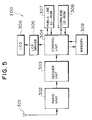
- Fig. 5 is a block diagram showing an example of the internal arrangement of the pager of the present invention.
- the pager 300 comprises an antenna unit 301 for receiving both a selective call signal from the general public telephone line and a selective call signal from the cordless telephone (the master unit 100 and the subsidiary unit 200), a radio unit 302 for demodulating the signal received by the antenna unit 301, a decoder unit 303 for digitizing the signal from the radio unit 302 and outputting the obtained digital signal, a control unit 304 for performing determination processing of a selective call number included in the signal from the decoder unit 303, an LCD driver 305 for controlling display on an LCD 306, the LCD 306 for displaying a message included in the signal from the decoder unit 303, a public line ID-ROM 307 storing the selective call signal of the pager, which is used to call the pager from the general public telephone line, a cordless ID-ROM 308 storing the selective call signal of the pager, which is used to call the pager from the master unit 100 or the subsidiary unit 200, and a memory 309 for temporarily storing the signal from the decoder unit 303, and
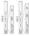
- Fig. 6 is a view showing an example of the format of the selective call signal from the general public telephone line.
- Fig. 7 is a view showing an example of the format of the selective signal from the cordless telephone.
- the selective call signal comprises a plurality of frames subsequent to a synchronizing signal.
- Each frame comprises an address number as the selective call number of the pager 300, a message signal as a message from the caller, and a check code used to check a transmission error and the like.
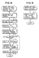
- Fig. 8 is a flow chart of selective call signal transmission processing in the cordless telephone master unit 100 shown in Fig. 3 and the cordless telephone subsidiary unit 200 shown in Fig. 4.
- Selective call signal transmission processing in the master unit 100 is the same as that in the subsidiary unit 200, and selective call signal transmission processing in the master unit 100 will be described below with reference to Fig. 3.
- the user of the master unit 100 depresses the pager calling switch 114 (D-1) and selects a target call pager through an input operating unit (not shown) (D-2).
- the control unit 104 reads out a selective call number corresponding to the pager selected in step (D-2) from the cordless ID-ROM 108 (D-3) and generates an address portion in the format shown in Fig. 7 (D-4).
- the user of the master unit 100 can cause the pager to display a desired message upon calling the pager 300.
- the control unit 104 When the user inputs this message (D-5 and D-6), the control unit 104 generates a message portion in the format shown in Fig. 7 (D-7).
- the master unit 100 transmits the generated selective call signal through the pager signal transmission unit 103 and the antenna 102.
- Fig. 9 is a flow chart showing selective call signal transmission processing performed when the general public telephone line is used.
- the paging system base station 5 shown in Fig. 1 transmits a selective call signal including a selective call number corresponding to a target call pager (E-1).
- Fig. 10 is a flow chart of selective call signal reception processing in the pager 300 shown in Fig. 5.
- the pager 300 Upon receiving a selective call signal including the selective call number assigned to the pager, the pager 300 compares the selective call number included in the signal received by the antenna unit 301 with the selective call numbers read out from the public line ID-ROM 307 and the cordless ID-ROM 308, thereby determining whether the selective call number included in the signal received by the antenna unit 301 corresponds to the general public telephone line or the cordless telephone (F-1). If the selective call number corresponds to the general public telephone line, a message for the general public telephone line (e.g., a message representing a call through the general public telephone line) is displayed on the LCD 306 (F-2). Otherwise, a message for the cordless telephone (e.g., a message representing a call from the cordless telephone) is displayed on the LCD 306 (F-3).
- a message for the general public telephone line e.g., a message representing a call through the general public telephone line
- a message for the cordless telephone e.g., a message representing a call from
- step (F-4) it is determined whether a message is included in the signal received by the antenna unit 301 (F-4). If a message is included, message signal processing is performed (F-5) to display the message (F-6), thereby ending the processing. If it is determined in step (F-4) that no message is included, a message representing that no message is included in the selective call signal is displayed (F-6), thereby ending the processing.
- the user can always call the radio selective calling receiver near a room or house within the range of several hundred meters from the cordless telephone master or subsidiary unit without using the general public telephone line and without being charged for the call.
- the radio selective calling receiver is much lighter-weighted than the cordless telephone subsidiary unit. Therefore, the suer can easily and always carry the receiver to obtain the information.
- the invention may allow a user to call a radio selective calling receiver (pager) near a room or house within a range of several hundred meters from a cordless telephone master or subsidiary unit without using a general public telephone line and without being charged for the call.
- the paging system includes a pager, and a cordless telephone master and subsidiary units capable of calling the pager.
Abstract
The invention may allow a user to call a radio selective calling receiver (pager) near a room or house within a range of several hundred meters from a cordless telephone master or subsidiary unit without using a general public telephone line and without being charged for the call. The paging system includes a pager, and a cordless telephone master and subsidiary units capable of calling the pager.
Description
- The present invention relates to a radio selective calling receiver and a cordless telephone system. Broadly, it provides a radio selective calling receiver adapted to be called through a general public telephone line from a cordless telephone without using the public telephone line, and a cordless telephone system.
- Recently, mobile communication is becoming increasingly popular, and various means for calling a moving person are provided. For example, with a radio selective calling receiver (pager), the carrier of the receiver can be called through a general public telephone line. A cordless telephone system comprises a master unit and one or more subsidiary units. The master unit can call the subsidiary unit, or a subsidiary unit can call another subsidiary unit.
- However, as for the radio selective calling receiver, the general public telephone line must be used to call the carrier of the receiver. Therefore, even when the person to be called is present near the caller, the caller is charged for every calling operation.
- When the person to be called always carries a subsidiary unit of the cordless telephone system, the user can call this person without being charged for the call as far as this person is within the area covered by the cordless telephone system. However, the subsidiary unit is larger in both size and weight than the radio selective calling receiver, e.g., weighs several hundred grams, resulting in poor portability.
- The present invention has been made in consideration of the above situation, and aims to provide a compact and lightweight highly portable paging system in which a user need not be charged for a call from a person near the user.
- According to an aspect of the present invention, there is provided a paging system comprising a radio selective calling receiver which can be directly called from a cordless telephone master unit or a subsidiary unit by using a frequency band for a paging terminal without using a telephone line, and a cordless telephone capable of transmitting a signal to the receiver. In an embodiment of the present invention, a cordless selective call number for each radio selective calling receiver is transmitted in accordance with a prescribed signal format. With this operation, as in the normal calling operation of the radio selective calling receiver, the selective call number and a message signal can be received.
- Preferably, with a system according to the present invention, the user can call the radio selective calling receiver near a room or house within the range of several hundred meters from the cordless telephone master or subsidiary unit without using the general public telephone line. Therefore, a person who always carries the light-weighted radio selective calling receiver can be called even outside the house as usual. When the carrier is near the house, the user can always call that person without being charged for the call.
- Fig. 1 is a view showing a conventional system configuration;
- Fig. 2 is a view showing an example of the system configuration of the present invention;
- Fig. 3 is a block diagram showing an example of the internal arrangement of a cordless telephone master unit of the present invention;
- Fig. 4 is a block diagram showing an example of the internal arrangement of a cordless telephone subsidiary unit of the present invention;
- Fig. 5 is a block diagram showing an example of the internal arrangement of a pager of the present invention;
- Fig. 6 is a view showing an example of the format of a selective call signal from a general public telephone line;
- Fig. 7 is a view showing an example of the format of a selective call signal from a cordless telephone;
- Fig. 8 is a flow chart of selective call signal transmission processing in the cordless telephone master unit shown in Fig. 3 and the cordless telephone subsidiary unit shown in Fig. 4;
- Fig. 9 is a flow chart of selective call signal transmission processing performed when the general public telephone line is used; and
- Fig. 10 is a flow chart of selective call signal reception processing in the pager shown in Fig. 5.
- An embodiment of the present invention will now be described below.
- Fig. 1 is a view showing a general configuration of a cordless telephone and paging terminals.
- A cordless
telephone master unit 1 has a normal function of speech communication using a general public telephone line and a function of speech communication with a cordless telephone subsidiary unit. Cordlesstelephone subsidiary units Reference numeral 4 denotes a house. - With this arrangement, to call one of the
pagers 3a to 3c from the cordlesstelephone master unit 1 or thesubsidiary unit system base station 5 through the normal telephone line, and a tone-only signal or a signal including a message is received. - Fig. 2 is a view showing an example of the configuration of the present invention.
- With this arrangement, to call one of the
pagers 3a to 3c near thehouse 4, a transmission function which allows transmission of the selective call number for the cordless telephone by using a frequency corresponding to the receiver in accordance with a transmission protocol corresponding to the paging terminal is arranged in themaster unit 1 and thesubsidiary units pagers 3a to 3c and an arbitrary message signal (unnecessary for a tone-only signal) are transmitted. With this operation, thepager house 4 can be called without using the general telephone line. - Fig. 3 is a block diagram showing an example of the internal arrangement of a cordless telephone master unit of the present invention.
- A
master unit 100 comprises anantenna 101 for transmitting/receiving a radio signal to/from a cordlesstelephone subsidiary unit 200 shown in Fig. 4, a cordlesstelephone radio unit 112 for modulating/demodulating the radio signal transmitted/received to/from the cordlesstelephone subsidiary unit 200, anantenna 102 for transmitting a selective call signal to apager 300 shown in Fig. 5, a pagersignal transmission unit 103 for modulating the selective call signal to be transmitted to thepager 300, acontrol unit 104 for controlling pager call processing, anLCD driver 105 for controlling display on anLCD 106, theLCD 106 for displaying various information including a telephone number, amemory 107 for temporarily storing the selective call signal to be transmitted, and the like, a cordless ID-ROM 108 storing the selective call number used to call thepager 300 from themaster unit 100, a speech input/output driver 109 for controlling aloudspeaker 110 and a microphone 111, theloudspeaker 110 arranged at the receiver of themaster unit 100 to perform speech communication, the microphone 111 arranged at the transmitter of themaster unit 100 to perform speech communication, a public lineconnection interface unit 113 for connecting themaster unit 100 to a public telephone line, and apager calling switch 114 depressed when the user calls thepager 300 from themaster unit 100. - Fig. 4 is a block diagram showing an example of the internal arrangement of the cordless telephone subsidiary unit of the present invention.
- The
subsidiary unit 200 comprises anantenna 201 for transmitting/receiving a radio signal to/from the cordlesstelephone master unit 100, a cordlesstelephone radio unit 212 for modulating/demodulating the radio signal transmitted/received to/from the cordlesstelephone master unit 100, anantenna 202 for transmitting a selective call signal to thepager 300 shown in Fig. 5, a pagersignal transmission unit 203 for modulating the selective call signal to be transmitted to thepager 300, acontrol unit 204 for controlling pager call processing, anLCD driver 205 for controlling display on anLCD 206, theLCD 206 for displaying various information including a telephone number, amemory 207 for temporarily storing the selective call signal to be transmitted, and the like, a cordless ID-ROM 208 storing the selective call number used to call thepager 300 from thesubsidiary unit 200, a speech input/output driver 209 for controlling aloudspeaker 210 and amicrophone 211, theloudspeaker 210 arranged at the receiver of thesubsidiary unit 200 to perform speech communication, themicrophone 211 arranged at the transmitter of thesubsidiary unit 200 to perform speech communication, and apager calling switch 213 depressed when the user calls thepager 300 from thesubsidiary unit 200. - Fig. 5 is a block diagram showing an example of the internal arrangement of the pager of the present invention.
- The
pager 300 comprises anantenna unit 301 for receiving both a selective call signal from the general public telephone line and a selective call signal from the cordless telephone (themaster unit 100 and the subsidiary unit 200), aradio unit 302 for demodulating the signal received by theantenna unit 301, adecoder unit 303 for digitizing the signal from theradio unit 302 and outputting the obtained digital signal, acontrol unit 304 for performing determination processing of a selective call number included in the signal from thedecoder unit 303, anLCD driver 305 for controlling display on anLCD 306, theLCD 306 for displaying a message included in the signal from thedecoder unit 303, a public line ID-ROM 307 storing the selective call signal of the pager, which is used to call the pager from the general public telephone line, a cordless ID-ROM 308 storing the selective call signal of the pager, which is used to call the pager from themaster unit 100 or thesubsidiary unit 200, and amemory 309 for temporarily storing the signal from thedecoder unit 303, and the like. - Fig. 6 is a view showing an example of the format of the selective call signal from the general public telephone line. Fig. 7 is a view showing an example of the format of the selective signal from the cordless telephone.
- As is apparent from Figs. 6 and 7, the selective call signal comprises a plurality of frames subsequent to a synchronizing signal. Each frame comprises an address number as the selective call number of the
pager 300, a message signal as a message from the caller, and a check code used to check a transmission error and the like. - An operation performed to call the pager from the cordless telephone and an operation performed to call the pager from the general public telephone line will be described below.
- Fig. 8 is a flow chart of selective call signal transmission processing in the cordless
telephone master unit 100 shown in Fig. 3 and the cordlesstelephone subsidiary unit 200 shown in Fig. 4. - Selective call signal transmission processing in the
master unit 100 is the same as that in thesubsidiary unit 200, and selective call signal transmission processing in themaster unit 100 will be described below with reference to Fig. 3. - First, the user of the
master unit 100 depresses the pager calling switch 114 (D-1) and selects a target call pager through an input operating unit (not shown) (D-2). - The
control unit 104 reads out a selective call number corresponding to the pager selected in step (D-2) from the cordless ID-ROM 108 (D-3) and generates an address portion in the format shown in Fig. 7 (D-4). - The user of the
master unit 100 can cause the pager to display a desired message upon calling thepager 300. When the user inputs this message (D-5 and D-6), thecontrol unit 104 generates a message portion in the format shown in Fig. 7 (D-7). Themaster unit 100 transmits the generated selective call signal through the pagersignal transmission unit 103 and theantenna 102. - Fig. 9 is a flow chart showing selective call signal transmission processing performed when the general public telephone line is used.
- This processing is the same as that of the conventional system shown in Fig. 1, and a detailed description thereof will be omitted. The paging
system base station 5 shown in Fig. 1 transmits a selective call signal including a selective call number corresponding to a target call pager (E-1). - Fig. 10 is a flow chart of selective call signal reception processing in the
pager 300 shown in Fig. 5. - Upon receiving a selective call signal including the selective call number assigned to the pager, the
pager 300 compares the selective call number included in the signal received by theantenna unit 301 with the selective call numbers read out from the public line ID-ROM 307 and the cordless ID-ROM 308, thereby determining whether the selective call number included in the signal received by theantenna unit 301 corresponds to the general public telephone line or the cordless telephone (F-1). If the selective call number corresponds to the general public telephone line, a message for the general public telephone line (e.g., a message representing a call through the general public telephone line) is displayed on the LCD 306 (F-2). Otherwise, a message for the cordless telephone (e.g., a message representing a call from the cordless telephone) is displayed on the LCD 306 (F-3). - Subsequently, it is determined whether a message is included in the signal received by the antenna unit 301 (F-4). If a message is included, message signal processing is performed (F-5) to display the message (F-6), thereby ending the processing. If it is determined in step (F-4) that no message is included, a message representing that no message is included in the selective call signal is displayed (F-6), thereby ending the processing.
- As has been described above, according to the present invention, the user can always call the radio selective calling receiver near a room or house within the range of several hundred meters from the cordless telephone master or subsidiary unit without using the general public telephone line and without being charged for the call. With this arrangement, even in a room far from the telephone or even outside close to the house, where no ringing of the telephone directly reaches, reception of an incoming call can be detected. In addition, the radio selective calling receiver is much lighter-weighted than the cordless telephone subsidiary unit. Therefore, the suer can easily and always carry the receiver to obtain the information.
- Each feature disclosed in the specification (which term includes the claims) and/or shown in the drawings may be incorporated in the invention independently of other disclosed and/or illustrated features.
- In summary, the invention may allow a user to call a radio selective calling receiver (pager) near a room or house within a range of several hundred meters from a cordless telephone master or subsidiary unit without using a general public telephone line and without being charged for the call. The paging system includes a pager, and a cordless telephone master and subsidiary units capable of calling the pager.
Claims (10)
- A paging system which can be called from a cordless telephone, comprising a radio selective calling receiver which can be directly called from a cordless telephone master unit or a subsidiary unit by using a frequency band for a paging terminal without using a telephone line, and said cordless telephone capable of transmitting a signal to said receiver.
- A system according to claim 1, wherein said radio selective calling receiver has two selective call signals including a selective call number used to receive a signal transmitted from a general public telephone line and a selective call number used to receive a signal transmitted from said cordless telephone master unit or said subsidiary unit.
- A system according to claim 1, wherein said cordless telephone master unit and said subsidiary unit can transmit a selective call number different from that transmitted from said general public telephone line by using the same frequency band as that of said general public telephone line.
- A paging system comprising a paging receiver (3a, 3b, 3c), a cordless telephone base unit (1), and a cordless telephone handset (2a, 2b) wherein at least one of the base unit (1) and the handset (2a, 2b) is adapted to transmit a paging signal on receipt of which the paging receiver (3a, 3b, 3c) is arranged to alert a user.
- A paging system according to Claim 4 wherein both the base unit (1) and the handset (2a, 2b) are adapted to transmit said paging signal.
- A paging system according to Claim 4 or Claim 5, wherein the paging receiver is arranged to receive a first paging signal from the cordless telephone base or handset, and receive a different paging signal from a remote paging station.
- A paging system according to Claim 6, wherein the paging signals are in the same frequency band.
- A paging receiver adapted for use in a system according to Claim 6 or Claim 7.
- A cordless telephone system adapted for use in a system according to any one of Claims 4 to 7.
- Use of a cordless telephone to transmit a paging request as a radio signal to a paging receiver.
Applications Claiming Priority (2)
| Application Number | Priority Date | Filing Date | Title |
|---|---|---|---|
| JP132112/95 | 1995-05-30 | ||
| JP13211295 | 1995-05-30 |
Publications (2)
| Publication Number | Publication Date |
|---|---|
| EP0746132A2 true EP0746132A2 (en) | 1996-12-04 |
| EP0746132A3 EP0746132A3 (en) | 1998-04-22 |
Family
ID=15073720
Family Applications (1)
| Application Number | Title | Priority Date | Filing Date |
|---|---|---|---|
| EP96303890A Withdrawn EP0746132A3 (en) | 1995-05-30 | 1996-05-30 | Paging system for a cordless telephone |
Country Status (5)
| Country | Link |
|---|---|
| US (1) | US6094583A (en) |
| EP (1) | EP0746132A3 (en) |
| KR (1) | KR100203970B1 (en) |
| CN (1) | CN1112063C (en) |
| TW (1) | TW301833B (en) |
Cited By (1)
| Publication number | Priority date | Publication date | Assignee | Title |
|---|---|---|---|---|
| WO2000046774A1 (en) * | 1999-02-08 | 2000-08-10 | Agere Systems Guardian Corp. | Object locator |
Families Citing this family (1)
| Publication number | Priority date | Publication date | Assignee | Title |
|---|---|---|---|---|
| JPWO2002052878A1 (en) * | 2000-12-25 | 2004-04-30 | 株式会社鷹山 | Wireless communication device, parent communication device, parent-child communication device, and wireless communication system |
Citations (4)
| Publication number | Priority date | Publication date | Assignee | Title |
|---|---|---|---|---|
| EP0212761A2 (en) * | 1985-08-28 | 1987-03-04 | Philips Electronics Uk Limited | Communications system |
| EP0263666A2 (en) * | 1986-10-06 | 1988-04-13 | Kabushiki Kaisha Toshiba | Cordless telephone apparatus |
| EP0369123A2 (en) * | 1988-11-18 | 1990-05-23 | Robert Bosch Gmbh | Flexless telephone |
| EP0478213A2 (en) * | 1990-09-26 | 1992-04-01 | Gpt Limited | Cordless communication system |
Family Cites Families (2)
| Publication number | Priority date | Publication date | Assignee | Title |
|---|---|---|---|---|
| US3976995A (en) * | 1975-05-22 | 1976-08-24 | Sanders Associates, Inc. | Precessing display pager |
| CA2064646A1 (en) * | 1991-04-02 | 1992-10-03 | Kipling W. Fyfe | Automatic number assignment module selection for mobile telephone |
-
1996
- 1996-05-29 CN CN96110031A patent/CN1112063C/en not_active Expired - Fee Related
- 1996-05-29 TW TW085106365A patent/TW301833B/zh active
- 1996-05-30 KR KR1019960018645A patent/KR100203970B1/en not_active IP Right Cessation
- 1996-05-30 EP EP96303890A patent/EP0746132A3/en not_active Withdrawn
- 1996-05-30 US US08/655,405 patent/US6094583A/en not_active Expired - Fee Related
Patent Citations (4)
| Publication number | Priority date | Publication date | Assignee | Title |
|---|---|---|---|---|
| EP0212761A2 (en) * | 1985-08-28 | 1987-03-04 | Philips Electronics Uk Limited | Communications system |
| EP0263666A2 (en) * | 1986-10-06 | 1988-04-13 | Kabushiki Kaisha Toshiba | Cordless telephone apparatus |
| EP0369123A2 (en) * | 1988-11-18 | 1990-05-23 | Robert Bosch Gmbh | Flexless telephone |
| EP0478213A2 (en) * | 1990-09-26 | 1992-04-01 | Gpt Limited | Cordless communication system |
Cited By (1)
| Publication number | Priority date | Publication date | Assignee | Title |
|---|---|---|---|---|
| WO2000046774A1 (en) * | 1999-02-08 | 2000-08-10 | Agere Systems Guardian Corp. | Object locator |
Also Published As
| Publication number | Publication date |
|---|---|
| CN1147750A (en) | 1997-04-16 |
| KR100203970B1 (en) | 1999-06-15 |
| KR960043589A (en) | 1996-12-23 |
| CN1112063C (en) | 2003-06-18 |
| EP0746132A3 (en) | 1998-04-22 |
| US6094583A (en) | 2000-07-25 |
| TW301833B (en) | 1997-04-01 |
Similar Documents
| Publication | Publication Date | Title |
|---|---|---|
| KR100306109B1 (en) | Response message transmitter for mobile phone devices | |
| JPH0323037B2 (en) | ||
| US5815800A (en) | Voice-pager system | |
| US4947420A (en) | Communication system | |
| US5905956A (en) | Method for identifying active handsets in a cordless telephone system | |
| GB2298552A (en) | Cordless radio telephone system with a plurality of portable units | |
| US6094583A (en) | Paging system adapted to be called from cordless telephone | |
| JP3037257B2 (en) | Security bell using PHS telephone system line | |
| JPS6062743A (en) | Mobile radio communication system | |
| JP3496481B2 (en) | Wireless communication device | |
| JPS6198057A (en) | Section party telephone set system within station yard | |
| JP2752994B2 (en) | Wireless telephone equipment | |
| JPH1117798A (en) | Selective call receiver | |
| JP2882350B2 (en) | Paging system that can be called from a cordless telephone | |
| KR100241779B1 (en) | Meet-me service access method in a ct-2 terminal | |
| JP3097787B2 (en) | Wireless telephone device control system | |
| JP3201245B2 (en) | Cordless phone system | |
| JPH07274226A (en) | Receiver | |
| KR20000013794A (en) | Short message service identifying method in telecommunication terminal | |
| JP2528398B2 (en) | Wireless communication method | |
| JP2722632B2 (en) | Wireless paging method | |
| JP3038975B2 (en) | Telephone equipment | |
| JP4980512B2 (en) | Mobile communication terminal | |
| KR100267863B1 (en) | Method for confirming voice message in digital radio telephone having pager | |
| JP3077249B2 (en) | Wireless telephone equipment |
Legal Events
| Date | Code | Title | Description |
|---|---|---|---|
| PUAI | Public reference made under article 153(3) epc to a published international application that has entered the european phase |
Free format text: ORIGINAL CODE: 0009012 |
|
| AK | Designated contracting states |
Kind code of ref document: A2 Designated state(s): DE GB |
|
| PUAL | Search report despatched |
Free format text: ORIGINAL CODE: 0009013 |
|
| AK | Designated contracting states |
Kind code of ref document: A3 Designated state(s): DE GB |
|
| 17P | Request for examination filed |
Effective date: 19980323 |
|
| 17Q | First examination report despatched |
Effective date: 20011030 |
|
| STAA | Information on the status of an ep patent application or granted ep patent |
Free format text: STATUS: THE APPLICATION IS DEEMED TO BE WITHDRAWN |
|
| 18D | Application deemed to be withdrawn |
Effective date: 20040302 |