EP0745982A2 - Tracking error signal generation device - Google Patents
Tracking error signal generation device Download PDFInfo
- Publication number
- EP0745982A2 EP0745982A2 EP96303968A EP96303968A EP0745982A2 EP 0745982 A2 EP0745982 A2 EP 0745982A2 EP 96303968 A EP96303968 A EP 96303968A EP 96303968 A EP96303968 A EP 96303968A EP 0745982 A2 EP0745982 A2 EP 0745982A2
- Authority
- EP
- European Patent Office
- Prior art keywords
- tracking error
- error signal
- light
- signal
- light detection
- Prior art date
- Legal status (The legal status is an assumption and is not a legal conclusion. Google has not performed a legal analysis and makes no representation as to the accuracy of the status listed.)
- Granted
Links
Images


Classifications
-
- G—PHYSICS
- G11—INFORMATION STORAGE
- G11B—INFORMATION STORAGE BASED ON RELATIVE MOVEMENT BETWEEN RECORD CARRIER AND TRANSDUCER
- G11B19/00—Driving, starting, stopping record carriers not specifically of filamentary or web form, or of supports therefor; Control thereof; Control of operating function ; Driving both disc and head
- G11B19/02—Control of operating function, e.g. switching from recording to reproducing
- G11B19/12—Control of operating function, e.g. switching from recording to reproducing by sensing distinguishing features of or on records, e.g. diameter end mark
-
- G—PHYSICS
- G11—INFORMATION STORAGE
- G11B—INFORMATION STORAGE BASED ON RELATIVE MOVEMENT BETWEEN RECORD CARRIER AND TRANSDUCER
- G11B7/00—Recording or reproducing by optical means, e.g. recording using a thermal beam of optical radiation by modifying optical properties or the physical structure, reproducing using an optical beam at lower power by sensing optical properties; Record carriers therefor
- G11B7/08—Disposition or mounting of heads or light sources relatively to record carriers
- G11B7/09—Disposition or mounting of heads or light sources relatively to record carriers with provision for moving the light beam or focus plane for the purpose of maintaining alignment of the light beam relative to the record carrier during transducing operation, e.g. to compensate for surface irregularities of the latter or for track following
- G11B7/0901—Disposition or mounting of heads or light sources relatively to record carriers with provision for moving the light beam or focus plane for the purpose of maintaining alignment of the light beam relative to the record carrier during transducing operation, e.g. to compensate for surface irregularities of the latter or for track following for track following only
-
- G—PHYSICS
- G11—INFORMATION STORAGE
- G11B—INFORMATION STORAGE BASED ON RELATIVE MOVEMENT BETWEEN RECORD CARRIER AND TRANSDUCER
- G11B7/00—Recording or reproducing by optical means, e.g. recording using a thermal beam of optical radiation by modifying optical properties or the physical structure, reproducing using an optical beam at lower power by sensing optical properties; Record carriers therefor
- G11B2007/0003—Recording, reproducing or erasing systems characterised by the structure or type of the carrier
- G11B2007/0006—Recording, reproducing or erasing systems characterised by the structure or type of the carrier adapted for scanning different types of carrier, e.g. CD & DVD
-
- G—PHYSICS
- G11—INFORMATION STORAGE
- G11B—INFORMATION STORAGE BASED ON RELATIVE MOVEMENT BETWEEN RECORD CARRIER AND TRANSDUCER
- G11B7/00—Recording or reproducing by optical means, e.g. recording using a thermal beam of optical radiation by modifying optical properties or the physical structure, reproducing using an optical beam at lower power by sensing optical properties; Record carriers therefor
- G11B7/007—Arrangement of the information on the record carrier, e.g. form of tracks, actual track shape, e.g. wobbled, or cross-section, e.g. v-shaped; Sequential information structures, e.g. sectoring or header formats within a track
-
- G—PHYSICS
- G11—INFORMATION STORAGE
- G11B—INFORMATION STORAGE BASED ON RELATIVE MOVEMENT BETWEEN RECORD CARRIER AND TRANSDUCER
- G11B7/00—Recording or reproducing by optical means, e.g. recording using a thermal beam of optical radiation by modifying optical properties or the physical structure, reproducing using an optical beam at lower power by sensing optical properties; Record carriers therefor
- G11B7/08—Disposition or mounting of heads or light sources relatively to record carriers
- G11B7/09—Disposition or mounting of heads or light sources relatively to record carriers with provision for moving the light beam or focus plane for the purpose of maintaining alignment of the light beam relative to the record carrier during transducing operation, e.g. to compensate for surface irregularities of the latter or for track following
- G11B7/0943—Methods and circuits for performing mathematical operations on individual detector segment outputs
Definitions
- the present invention generally relates to a tracking error signal generation device used in an apparatus for reproducing and/or recording an optical record medium, and more particularly to a tracking error signal generation device used in an apparatus for reproducing and/or recording an optical record medium of one type among various types which track pitches are different from each other.
- the light beam should precisely follow the signal track in order to record and/or reproduce the information correctly.
- the tracking control to generate a tracking error signal indicating a shift of the light beam from the desired signal track and reduce the shift on the basis of the generated tracking error signal is performed in this kind of apparatus for recording and/or reproducing the optical record medium.
- the 3 beams method is such a method that three beams i. e. a main beam for recording or reproducing the information, a first sub beam for moving ahead of the main beam to generate the tracking error signal, and a second sub beam for moving behind the main beam to generate the tracking error signal are used, which are arranged such that a straight line connecting the centers of those 3 beams forms a predetermined angle corresponding to the track pitch of the signal track with respect to the information reading direction. Further, at the position corresponding to the reflection light of each of the first and second sub beams from the optical record medium, the light receiving surface of the light detection element is disposed respectively.
- the incident (reflection) light amount to the light detection element corresponding to the first sub beam and the incident (reflection) light amount to the light detection element corresponding to the second sub beam are substantially equal to each other, so that the difference between them substantially becomes zero.
- the main beam is substantially on the center line of the signal track at this moment.
- the incident (reflection) light amount to the light detection element corresponding to the first sub beam and the incident (reflection) light amount to the light detection element corresponding to the second sub beam are unbalanced and different from each other.
- the sign and the value (magnitude) of the difference between them it can be found in which direction and how much magnitude the main beam is shifted from the center line of the signal track at this moment.
- the tracking control can be performed by moving the light beams in the direction to reduce the shift.
- the tracking error signal is calculated out of the light detection signals obtained from a plurality of light beams, which generate push pull signals different in phase from each other such that the in phase offset component due to the disk skew and the movement of the objective lens can be canceled.
- this method there still exists the optimum beam arrangement in dependence on the track pitch of the signal track in the way similar to the aforementioned 3 beams method. Thus, the aforementioned problem is still raised.
- the phase of the heterodyne signal obtained by four divided light receiving surfaces of the light detection element is detected with respect to the RF signal as the standard, and the radial error signal of both polarities is generated.
- this method there still exists the optimum beam arrangement in dependence on the track pitch of the signal track in the way similar to the aforementioned 3 beams method. Thus, the aforementioned problem is still raised.
- the above object of the present invention can be achieved by a first tracking error signal generation device used for an optical pickup device capable of reproducing and/or recording an information signal on a spiral or coaxial signal track of a disk shaped optical record medium of one type among a plurality of optical record media of different types which track pitches are different from each other.
- the optical pickup device is provided with: a light beam irradiation device for irradiating the optical record medium with a main beam for forming a main beam spot on the signal track, a first sub beam for forming a first sub beam spot on the optical record medium ahead of the main beam spot and a second sub beam for forming a second sub beam spot behind the main beam spot; a first light detection device having at least two light receiving surfaces which are divided by a boundary line substantially parallel to a tangent direction of the signal track for receiving a reflection light of the first sub beam and outputting first and second light detection signals S1 and S2 indicating light amounts received by the two light receiving surfaces thereof respectively; a second light detection device having at least two light receiving surfaces which are divided by a boundary line substantially parallel to the tangent direction for receiving a reflection light of the main beam and outputting third and fourth light detection signals S3 and S4 indicating light amounts received by the two light receiving surfaces thereof respectively; and a third light detection device having at least two light receiving surfaces which are divided by a boundary line
- the first tracking error signal generation device is provided with: a first operation device, to which the first, second, fifth and sixth light detection signals S1, S2, S5 and S6 are inputted, for adding the first and second light detection signals S1 and S2 to output its result as a first addition signal, adding the fifth and sixth light detection signals S5 and S6 to output its result as a second addition signal, and subtracting one of the first and second addition signals from the other to output its result as a first tracking error signal according to a three beams method; and a second operation device, to which the first to sixth light detection signals S1 to S6 are inputted, for calculating a second tracking error signal SE according to a DPP (Differential Push Pull) method expressed by an expression (1), in case that the light receiving surfaces respectively corresponding to the first and fifth light detection signals S1 and S5 are arranged on one straight line including the radius of the optical record medium at positions corresponding to directions same to each other of the signal track with respect to the boundary line, and that the light receiving surfaces respectively corresponding to the second and
- the first tracking error signal generation device is further provided with: a selecting device for selecting one of the first tracking error signal and the second tracking error signal SE on the basis of an instruction from the external, and outputting the selected signal as an output tracking error signal.
- the first, second, fifth and sixth light detection signals S1, S2, S5 and S6 are inputted to the first operation device. Then, the first operation device adds the first and second light detection signals S1 and S2, adds the fifth and sixth light detection signals S5 and S6, and subtracts one of the first and second addition signals from the other to output the first tracking error signal according to the three beams method. On the other hand, the first to sixth light detection signals S1 to S6 are inputted to the second operation device. Then, the second operation device calculates the second tracking error signal SE according to the DPP method expressed by the expression (1), in case that the light receiving surfaces are arranged in a certain manner with respect to the disk shaped optical record medium and the boundary line. Finally, the selecting device selects one of the first tracking error signal and the second tracking error signal SE on the basis of an instruction from the external, and the selected signal is outputted as the output tracking error signal.
- the first tracking error signal is the tracking error signal according to the three beams method while the second tracking error signal is the tracking error signal according to the DPP method
- one portion of the present tracking error signal generation device as well as one portion of the light detection elements in the optical pickup device can be commonly used as a tracking error signal generation circuit by means of the three beams method and a tracking error signal generation circuit by means of the DPP method. Consequently, the construction of the optical pickup device for reproducing and/or recording the optical record medium of one type among various types whose track pitches are different from each other such as the CD, the DVD, etc., can be simplified, and the adjustment of the optical system and signal processing for various types of the optical record media can be also simplified according to the present invention.
- the optical record media include a first optical record medium of one type having a first track pitch and a second optical record medium of another type having a second track pitch which is substantially half of the first track pitch.
- a shift amount of the first and second sub beam spots with respect to the main beam spot in a radial direction of each of the first and second optical record media is set to substantially 1/4 of the first track pitch.
- the selecting device selects the first tracking error signal for the first optical record medium and selects the second tracking error signal SE for the second optical record medium on the basis of the instruction from the external.
- the light beam irradiation positions of the main beam and the first and second sub beams to obtain the optimum sensitivity in case of generating the tracking error signal by means of the three beams method with respect to the first optical record medium is coincident with that to obtain the optimum sensitivity in case of generating the tracking error signal by means of the DPP method with respect to the second optical record medium.
- the selecting device has a second switch for switching an output of the selecting device to one of the first operation device and the second operation device, and the first tracking error signal generation device is further provided with a controller for generating a switch control signal on the basis of the instruction from the external, and controlling the first and second switches by the switch control signal.
- the controller generates a switch control signal on the basis of the instruction from the external, and the first and second switches are controlled by the switch control signal.
- the switching operation with respect to the optical record media of various types can be reliably and speedily performed according to this aspect.
- the predetermined constant K used in the expression (1) is equal to 1.
- the predetermined constant K may be not equal to 1 depending on the difference in the light intensity of the main beam and the first or second sub beam, the difference in the light sensitivity of the light detection device, etc., so as to compensate the influence of the difference onto the second tracking error signal SE.
- the above object of the present invention can be achieved by a second tracking error signal generation device used for an optical pickup device capable of reproducing and/or recording an information signal on a spiral or coaxial signal track of a disk shaped optical record medium of one type among a plurality of optical record media of different types which track pitches are different from each other.
- the optical pickup device is provided with: a light beam irradiation device for irradiating the optical record medium with a main beam for forming a main beam spot on the signal track, a first sub beam for forming a first sub beam spot on the optical record medium ahead of the main beam spot and a second sub beam for forming a second sub beam spot behind the main beam spot; a first light detection device having a light receiving surface D1 for receiving a reflection light of the first sub beam and outputting a first light detection signal S1 indicating a light amount received by the light receiving surface D1; a second light detection device having at least four light receiving surfaces D2 to D5 which are divided by a first boundary line substantially parallel to a tangent direction of the signal track and by a second boundary line substantially orthogonal to the tangent direction for receiving a reflection light of the main beam and outputting second to fifth light detection signals S2 to S5 indicating light amounts received by the four light receiving surfaces D2 to D5 respectively; and a third light detection device having a light receiving
- the second tracking error signal generation device is provided with: a first operation device, to which the first and sixth light detection signals S1 and S6 are inputted, for subtracting one of the first and sixth light detection signals S1 and S6 from the other to output its result as a first tracking error signal according to a three beams method; and a second operation device, to which the second to fifth light detection signals S2 to S5 are inputted, for calculating a second tracking error signal according to a heterodyne method based on an addition signal SADD expressed by an expression (2) and a difference signal SDEF expressed by an expression (3), in case that the light receiving surfaces D2, D3, D4 and D5 are respectively disposed in second, first, third and fourth quadrants with respect to the first and second boundary lines assuming that a direction of the first boundary line corresponding to an information reading direction of the optical record medium is positive and a direction of the second boundary line corresponding to a direction from an inner circumference to an outer circumference of the optical record medium is positive to define the first to fourth quadrants, SADD
- the second tracking error signal generation device is further provided with: a selecting device for selecting one of the first and second tracking error signals on the basis of an instruction from the external, and outputting the selected signal as an output tracking error signal.
- the first and sixth light detection signals Sl and 56 are inputted to the first operation device. Then, the first operation device subtracts one of the first and sixth light detection signals S1 and S6 from the other to output its result as the first tracking error signal according to the three beams method.
- the second to fifth light detection signals S2 to S5 are inputted to the second operation device. Then, the second operation device calculates the second tracking error signal according to the heterodyne method based on the addition signal SADD expressed by the expression (2) and the difference signal SDEF expressed by an expression (3), in case that the light receiving surfaces are arranged in a certain manner with respect to the first to fourth quadrants based on the boundary lines. Finally, the selecting device selects one of the first and second tracking error signals on the basis of the instruction from the external, and the selected signal is outputted as the output tracking error signal.
- the first tracking error signal is the tracking error signal according to the three beams method while the second tracking error signal is the tracking error signal according to the heterodyne method
- one portion of the present tracking error signal generation device as well as one portion of the light detection elements in the optical pickup device can be commonly used as a tracking error signal generation circuit by means of the three beams method and a tracking error signal generation circuit by means of the heterodyne method. Consequently, the construction of the optical pickup device for reproducing and/or recording the optical record medium of one type among various types whose track pitches are different from each other such as the CD, the DVD, etc., can be simplified, and the adjustment of the optical system and signal processing for various types of the optical record media can be also simplified according to the present invention.
- the selecting device has a switch for switching an output of the selecting device to one of the first operation device and the second operation device, and the second tracking error signal generation device is further provided with a controller for generating a switch control signal on the basis of the instruction from the external, and controlling the switch by the switch control signal.
- the controller generates a switch control signal on the basis of the instruction from the external, and the switch is controlled by the switch control signal.
- the switching operation with respect to the optical record media of various types can be reliably and speedily performed according to this aspect.
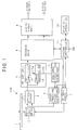
- FIG. 1 shows a block diagram of a compatible optical disk player capable of reproducing a CD (Compact Disk) and a DVD (Digital Video Disk) as optical disks.
- CD Compact Disk
- DVD Digital Video Disk
- a compatible optical disk player 100 is provided with: a spindle motor 2 for rotationally driving an optical disk 1; a spindle servo circuit 3 for performing the spindle servo operation of the spindle motor 2; an optical pickup 4 for irradiating the optical disk 1 with a reproduction light beam, receiving the reflected light from the optical disk 1, and outputting a light detection signal (RF signal); and a servo circuit 5 for performing a tracking servo control, a focus servo control and a carriage servo control on the basis of servo control signals.
- RF signal light detection signal
- the compatible optical disk player 100 is also provided with: an RF (Radio Frequency) amplifier unit 6 for amplifying the light detection signal of the optical pickup 4, and generating and outputting various error signals; an equalizer unit 7 for outputting the servo control signals for performing the tracking servo control, the focus servo control and the carriage servo control on the basis of the error signals outputted from the RF amplifier unit 6; a decoder unit 8 for decoding the amplified light detection signal outputted by the RF amplifier unit 6 and outputting the decoded video data and the decoded audio data; and an audio/video unit 9 for generating a video output signal and an audio output signal on the basis of the decoded video data and the decoded audio data.
- the compatible optical disk player 100 is further provided with: a display and operation unit 10 for displaying various data and performing various input operations; and a system controller 11 for performing the over all control of the compatible optical disk player 100.
- the RF amplifier unit 6 is provided with: an RF amplifier 12 for amplifying the light detection signal and outputting it as the amplified light detection signal; and an error signal generation circuit 13 for generating and outputting the error signals (e. g. the tracking error signal, the focus error signal, the carriage error signal) on the basis of the light detection signal.
- an RF amplifier 12 for amplifying the light detection signal and outputting it as the amplified light detection signal
- an error signal generation circuit 13 for generating and outputting the error signals (e. g. the tracking error signal, the focus error signal, the carriage error signal) on the basis of the light detection signal.
- FIG. 2 shows a circuit diagram of a tracking error signal generation circuit 20, which is included in the error generation circuit 13 of FIG. 1, and a main portion of the optical pickup 4, which is disposed at the tracking error signal generation circuit 20.
- the optical pickup 4 is provided with: a first light detection element D1 having a first light receiving surface B1 and a second light receiving surface B2 which receive the reflection light of the first sub beam from the optical disk 1; a second light detection element D2 having first to fourth light receiving surfaces A1 to A4 which receive the reflection light of the main beam from the optical disk 1; and a third light detection element D3 having a first light receiving surface C1 and a second light receiving surface C2 which receive the reflection light of the second sub beam from the optical disk 1.
- the tracking error signal generation circuit 20 is provided with: a first switch 21, to which an output signal S B1 of the first light receiving surface B1 of the first light detection element D1 and an output signal S C2 of the second light receiving surface C2 of the third light detection element D3, outputting the output signal S B1 from either one of a first output terminal T 01 and a second output terminals T 02 and outputting the output signal S C2 from the other of the output terminals T 01 and T 02 on the basis of a switch control signal S SW ; a first adder 22, to which the output signal S B2 of the second light receiving surface B2 of the first light detection element D1 is inputted at one of the input terminals and to which the output signal of the first output terminal T 01 is inputted at the other of the input terminals, for adding the input signals of both input terminals to output it as a first addition signal A S1 ; a second adder 23, to which the output signal S C1 of the first light receiving surface C1 of the third light detection element D3 is inputted at one of the input terminal
- the tracking error signal generation circuit 20 is also provided with: a first subtracter 26, to which the first addition signal A S1 is inputted at a non-inverted input terminal and to which the second addition signal A S2 is inputted at an inverted input terminal, for subtracting the input signals to output the difference between the first addition signal A S1 and the second addition signal A S2 as a first difference signal D S1 ; and a second subtracter 27, to which the third addition signal A S3 is inputted at a non-inverted input terminal and to which the fourth addition signal A S4 is inputted at an inverted input terminal, for subtracting the input signals to output the difference between the third addition signal A S3 and the fourth addition signal A S4 as a second difference signal D S2 .
- the predetermined constant K to compensate the light intensity difference between the main beam and the first or second sub beams, the light sensitivity difference between the second light detection element D2 and the first or third light detection element D1 or D3, and so on, is set in advance to the multiplier 28.
- each of the first and second switches 21 and 30 is the 3 beam side (i. e. the side for performing the tracking error signal generation by means of the 3 beams method), while the lower side of each of the first and second switches 21 and 30 is the DPP side (i. e. the side for performing the tracking error signal generation by means of the DPP method).
- the 3 beams method is employed as the method of generating the tracking error signal at the time of reproducing the CD as the optical disk 1
- the DPP (Differential Push Pull) method is employed as the method of generating the tracking error signal at the time of reproducing the DVD, and that the wave length of each light beam and each beam spot diameter suitable for the DVD reproduction are employed.
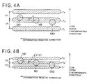
- the relationship between the signal tracks T1 to T3 and each of a beam spot MB formed by the main beam, a beam spot SB1 formed by the first sub beam and a beam spot SB2 formed by the second sub beam at the time of reproducing the CD (when the beam spots are on the track) are as shown in FIG. 4A.
- the relationship between the signal tracks T1' to T3' and each of the beam spots MB, SB1 and SB2 at the time of reproducing the DVD (when the center of the beam spot MB is on the track) are as shown in FIG. 4B,
- the system controller 11 controls the servo circuit 5 to turn on the focus servo (i. e. change the condition of the focus servo to the closed condition) (step S1).
- step S2 the system controller 11 starts the rotation driving of the spindle motor 2 via the spindle servo unit 3 (step S2).
- the system controller 11 switches the first switch 21 and the second switch 30 by the switch control signal S SW to the 3 beam side (as shown in FIG. 2) (step S3).
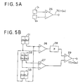
- the tracking error signal generation circuit 20 becomes substantially equivalent to a tracking error signal generation circuit by means of the 3 beams method shown in FIG. 5A.
- the equivalent circuit generates the first difference signal D S1 out of the light detection signals from the light detection elements D1 and D2, and outputs it as the tracking error signal TE by means of the 3 beam method.
- the optical disk 1 to be reproduced is the DVD
- the tracking error signal generation circuit 20 becomes substantially equivalent to the tracking error signal generation circuit by means of the DPP method shown in FIG. 5B, so that the operation for harmonizing the tracking error signal to the type of the optical disk 1 is completed in the condition that the reproduction of the DVD is possible.
- the equivalent circuit generates the first difference signal D S3 out of the light detection signals from the light detection elements D1, D2 and D3, and outputs it as the tracking error signal TE by means of the 3 beam method.
- the light detection signals are inputted to the equivalent circuit in FIG. 5B.
- the system controller 11 controls the servo circuit 5 to turn on the focus servo (i.e. change the condition of the focus servo to the closed condition) (step S11).
- step S12 the system controller 11 starts the rotation driving of the spindle motor 2 via the spindle servo unit 3 (step S12).
- the system controller 11 switches the first switch 21 and the second switch 30 by the switch control signal S SW to the 3 beam side (as shown in FIG. 2) (step S13).
- the tracking error signal generation circuit 20 becomes substantially equivalent to the tracking error signal generation circuit by means of the 3 beams method of FIG. 5A.
- the system controller 11 controls the servo circuit 5 to turn on the tracking servo (i.e. change the condition of the tracking servo to the closed condition) (step S14).
- step S15 it is judged whether or not a predetermined time t has elapsed from the time of turning on the tracking servo (step S15). If it the predetermined time t has elapsed (step S15: YES), it is further judged whether or not the PLL (Phase Locked Loop) which forms the tracking servo loop is locked (step S16).
- PLL Phase Locked Loop
- the obtained light detection signal (RF signal) is read and decoded by the decoder unit 8 (step S17), and by reading the TOC (Table Of Contents) information for example, it is judged whether or not the optical disk 1 to be reproduced is the CD (step S18).
- the system controller 11 switches the first switch 21 and the second switch 30 to the DPP side by the switch control signal S SW (Step S19).
- the tracking error signal generation circuit 20 becomes substantially equivalent to the tracking error signal generation circuit by means of the DPP method shown in FIG. 5B, so that the operation for harmonizing the tracking error signal to the type of the optical disk 1 is completed in the condition that the reproduction of the DVD is possible.
- the system controller 11 switches the first switch 21 and the second switch 30 to the DPP side by the switch control signal S SW (step S20).
- the system controller 11 controls the servo circuit 5 to turn on the tracking servo (i. e. change the condition of the tracking servo to the closed condition) (step S21).
- step S22 it is judged whether or not a predetermined time t has elapsed from the time of turning on the tracking servo (step S22). If the predetermined time t has elapsed (step S22: YES), it is further judged whether or not the PLL (Phase Locked Loop) which forms the tracking servo loop is locked (step S23).
- PLL Phase Locked Loop
- step S23 if the PLL is judged to be locked (YES), it is estimated that the optical disk 1 to be reproduced is the DVD.
- the obtained light detection signal (RF signal) are read and decoded by the decoder unit 8 (step S24), and by reading the TOC information for example, it is judged whether or not the optical disk 1 to be reproduced is recorded by the format of the DVD (step S25).
- the system controller 11 switches the first switch 21 and the second switch 30 to the 3 beam side by the switch control signal S SW (step S26).
- the tracking error signal generation circuit 20 becomes substantially equivalent to the tracking error signal generation circuit by means of the 3 beams method shown in FIG. 5A, so that the operation for harmonizing the tracking error signal to the type of the optical disk 1 is completed in the condition that the reproduction of the CD is possible.
- one portion of the tracking signal error signal generation circuit by means of the 3 beams method and one portion of the tracking error signal generation circuit by means of the DPP method are shared to each other, and one portion of the light detection element constituting the optical pickup is commonly used to those circuits. Therefore, the construction of the optical pickup for reproducing the optical record medium of one type among various types whose track pitches are different from each other such as the CD and the DVD can be simplified, and the adjustment of the optical system and signal processing for various types of the optical disk 1 can be also simplified according to the present embodiment.
- ⁇ ' TP2 / 2
- the tracking error signal generation apparatus of the present embodiment is adapted to the reproducing apparatus (i.e. the player) in the above explanation, but it can be adapted in the same manner to the recording apparatus.
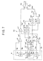
- a tracking error signal generation apparatus as a second embodiment of the present invention will be explained with referring to FIGs. 7 and 8.
- the tracking error signal generation circuit of the second embodiment is different from that of the first embodiment in that the 3 beams method and the heterodyne method are employed in the tracking error signal generation circuit in place of the 3 beams method and the DPP method of the first embodiment.
- the tracking error signal generation circuit 40 is provided with: a first adder 41, to which the output signal S B1 of the first light receiving surface B1 and the output signal S B2 of the second light receiving surface B2 of the first light detection element D1 are inputted, for adding these input signals to outputting it as a first addition signal A S1 '; a second adder 42, to which the output signal S A2 of the second light receiving surface A2 and the output signal S A3 of the third light receiving surface A3 of the second light detection element D2 are inputted, for adding these input signals to outputting it as a second addition signal A S2 '; a third adder 43, to which the output signal S A1 of the first light receiving surface A1 and the output signal S A4 of the fourth light receiving surface A4 of the second light detection element D2 are inputted, for adding these input signals to outputting it as a third addition signal A S3 '; a fourth adder 44, to which the output signal S C1 of the first light receiving surface C1 and the output signal
- the tracking error signal generation circuit 40 is also provided with: a first subtracter 46, to which the third addition signal A S3 ' is inputted at an inverted input terminal and to which the second addition signal A S2 ' is inputted at a non-inverted input terminal, for subtracting the input signals to output the difference between the second addition signal A S2 ' and the third addition signal A S3 ' as a first difference signal D S1 '; and a second subtracter 47, to which the first addition signal A S1 ' is inputted at a non-inverted input terminal and to which the fourth addition signal A S4 ' is inputted at an inverted input terminal, for subtracting the input signals to output the difference between the first addition signal A S1 ' and the fourth addition signal A S4 ' as a second difference signal D S2 '.
- a first subtracter 46 to which the third addition signal A S3 ' is inputted at an inverted input terminal and to which the second addition signal A S2 ' is inputted at a non-inverted input terminal,
- the tracking error signal generation circuit 40 is also provided with: a rising pulse generation circuit (RPG) 48 for detecting the signal-rise-up of the fifth addition signal A S5 ' and generating a rising pulse signal PR corresponding to the rising-up timing; a falling pulse generation circuit (FPG) 49 for detecting the signal-fall-down of the fifth addition signal A S5 ' and generating a falling pulse signal PF corresponding to the falling-down timing; a first sample hold circuit (S/H) 50 for sampling and holding the first difference signal D S1 ' by use of the rising pulse PR as the sampling timing signal, to output it as a first sample hold signal SH1; and a second sample hold circuit (S/H) 51 for sampling and holding the first difference signal D S1 ' by use of the falling pulse PF as the sampling timing signal, to output it as a second sample hold signal SH2.
- RPG rising pulse generation circuit
- FPG falling pulse generation circuit
- the tracking error signal generation circuit 40 is also provided with: a third subtracter 52, to which the first sample hold signal SH1 is inputted at a non-inverted input terminal and to which the second sample hold signal SH2 is inputted at an inverted input terminal, for subtracting the input signals to output the difference between the first sample hold signal SH1 and the second sample hold signal SH2 as a third difference signal D S3 '; and a switch 53, to which the second difference signal D S2 ' and the third difference signal D S3 ' are inputted, for outputting one of the difference signals as the tracking error signal TE on the basis of a switch control signal S SW .
- the upper side of the switch 53 is the 3 beam side (i. e. the side for performing the tracking error signal generation by means of the 3 beams method), while the lower side of the switch 53 is the heterodyne side (i. e. the side for performing the tracking error signal generation by means of the heterodyne method).
- the 3 beams method is employed as the method of generating the tracking error signal at the time of reproducing the CD as the optical disk 1
- the heterodyne method is employed as the method of generating the tracking error signal at the time of reproducing the DVD, and that the wave length of each light beam and each beam spot diameter suitable for the DVD reproduction are employed.
- the relationship between the signal tracks T1 to T3 and each of the beam spots MB, SB1 and SB2 at the time of reproducing the CD (when the beam spot MB is on the track) are as shown in FIG. 4A.
- the relationship between the signal tracks T1' to T3' and each of the beam spots MB, SB1 and SB2 at the time of reproducing the DVD (when the beam spot MB is on the track) are as shown in FIG. 4B,
- the system controller 11 controls the servo circuit 5 to turn on the focus servo (i. e. change the condition of the focus servo to the closed condition).
- system controller 11 starts the rotation driving of the spindle motor 2 via the spindle servo unit 3.
- the system controller 11 switches the switch 53 by the switch control signal S SW to the 3 beam side (as shown in FIG. 7).
- the tracking error signal generation circuit 40 becomes substantially equivalent to a tracking error signal generation circuit by means of the 3 beams method shown in FIG. 5A.
- the optical disk 1 to be reproduced is the CD
- the compared level is supposed to be higher than the predetermined level in case of generating the tracking error signal by means of the 3 beams method.
- the optical disk 1 to be reproduced is the DVD, since three beam spots MB, SB1 and SB2 are formed in a condition shown in FIG. 4B, the compared level is supposed to be not higher than the predetermined level in case of generating the tracking error signal by means of the 3 beams method.
- the system controller 11 switches the switch 53 to the heterodyne side (lower side in FIG. 7) so as to perform the generation of the tracking error by means of the heterodyne method.
- the tracking error signal generation circuit 40 becomes substantially equivalent to the tracking error signal generation circuit by means of the heterodyne method shown in FIG. 8, so that the operation for harmonizing the tracking error signal to the type of the optical disk 1 is completed in the condition that the reproduction of the DVD is possible.
- the second to fifth light detection signals S2 to S5 are inputted to the equivalent circuit in FIG. 8.
- one portion of the light detection element constituting the optical pickup is commonly used by the tracking signal error signal generation circuit by means of the 3 beams method and the tracking error signal generation circuit by means of the heterodyne method.
- the construction of the optical pickup for reproducing the optical record medium of one type among various types whose track pitches are different from each other such as the CD and the DVD can be simplified, and the adjustment of the optical system and the signal processing for the type of the optical disk 1 can be also simplified according to the present embodiment.
- the tracking error signal generation device of the present embodiment is adapted to the reproducing apparatus (i.e. the player) in the above explanation, but it can be adapted in the same manner to the recording apparatus.
- the light detection element for the DPP method is used as the first light detection element D1 and as the third light detection element D3, so that each of the light detection elements D1 and D3 has 2-divided light receiving surfaces.
- a light detection element having just one light receiving surface B is employed as the first light detection element D1
- a light detection element having just one light receiving surface C is employed as the third light detection element D3.
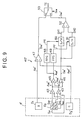
- the first adder 41 and the fourth adder 44 in FIG. 7 of the second embodiment are omitted in the construction of the third embodiment. Otherwise, the construction as well as the operation of the third embodiment is the same as those of the second embodiment.
Landscapes
- Optical Recording Or Reproduction (AREA)
Abstract
Description
- The present invention generally relates to a tracking error signal generation device used in an apparatus for reproducing and/or recording an optical record medium, and more particularly to a tracking error signal generation device used in an apparatus for reproducing and/or recording an optical record medium of one type among various types which track pitches are different from each other.
- In the apparatus for recording the information onto an optical record medium such as a CD (Compact Disk), a LD (Laser Disk), a DVD (Digital Video Disk) etc., by use of a light beam, and the apparatus for reproducing the information from such an optical record medium by use of the light beam, the light beam should precisely follow the signal track in order to record and/or reproduce the information correctly.
- For this purpose, the tracking control to generate a tracking error signal indicating a shift of the light beam from the desired signal track and reduce the shift on the basis of the generated tracking error signal is performed in this kind of apparatus for recording and/or reproducing the optical record medium.
- As one method of generating the tracking error signal, there is the "3 beams method".
- The 3 beams method is such a method that three beams i. e. a main beam for recording or reproducing the information, a first sub beam for moving ahead of the main beam to generate the tracking error signal, and a second sub beam for moving behind the main beam to generate the tracking error signal are used, which are arranged such that a straight line connecting the centers of those 3 beams forms a predetermined angle corresponding to the track pitch of the signal track with respect to the information reading direction. Further, at the position corresponding to the reflection light of each of the first and second sub beams from the optical record medium, the light receiving surface of the light detection element is disposed respectively.
- By this, if the main beam is substantially on the center line of the signal track, the incident (reflection) light amount to the light detection element corresponding to the first sub beam and the incident (reflection) light amount to the light detection element corresponding to the second sub beam are substantially equal to each other, so that the difference between them substantially becomes zero. Thus, it can be found that the main beam is substantially on the center line of the signal track at this moment.
- On the contrary, if the main beam is at a position shifted from the center line of the signal track, the incident (reflection) light amount to the light detection element corresponding to the first sub beam and the incident (reflection) light amount to the light detection element corresponding to the second sub beam are unbalanced and different from each other. Thus, by checking the sign and the value (magnitude) of the difference between them, it can be found in which direction and how much magnitude the main beam is shifted from the center line of the signal track at this moment.
- As a result, the tracking control can be performed by moving the light beams in the direction to reduce the shift.
- In the tracking control by means of the above explained 3 beams method, there exists an optimum beam arrangement in dependence on the track pitch of the signal track. Thus, in a compatible information recording apparatus, a compatible reproducing apparatus, a compatible information recording and reproducing apparatus for recording and/or reproducing the information with respect to various types of optical record media, which track pitches are different from each other, it is necessary to employ a plurality of optical systems capable of obtaining various optimum beam arrangements correspondingly. This results in that the number of adjusting members in the apparatus is increased, and the operation required for the adjustment is also increased, which is the problem.
- As another method of generating the tracking error signal, there is the "DPP (Differential Push Pull) method". In this DPP method, the tracking error signal is calculated out of the light detection signals obtained from a plurality of light beams, which generate push pull signals different in phase from each other such that the in phase offset component due to the disk skew and the movement of the objective lens can be canceled. However in this method, there still exists the optimum beam arrangement in dependence on the track pitch of the signal track in the way similar to the aforementioned 3 beams method. Thus, the aforementioned problem is still raised.
- As another method of generating the tracking error signal, there is the "heterodyne method". In this heterodyne method, the phase of the heterodyne signal obtained by four divided light receiving surfaces of the light detection element is detected with respect to the RF signal as the standard, and the radial error signal of both polarities is generated. However in this method, there still exists the optimum beam arrangement in dependence on the track pitch of the signal track in the way similar to the aforementioned 3 beams method. Thus, the aforementioned problem is still raised.
- It is therefore an object of the present invention to provide a tracking error signal generation device, which can simplify the construction and adjustment of the optical pickup used in the compatible reproducing apparatus, the compatible recording apparatus and the compatible recording and reproducing apparatus which deal with the optical record medium of one type among various types which track pitches are different form each other.
- The above object of the present invention can be achieved by a first tracking error signal generation device used for an optical pickup device capable of reproducing and/or recording an information signal on a spiral or coaxial signal track of a disk shaped optical record medium of one type among a plurality of optical record media of different types which track pitches are different from each other. The optical pickup device is provided with: a light beam irradiation device for irradiating the optical record medium with a main beam for forming a main beam spot on the signal track, a first sub beam for forming a first sub beam spot on the optical record medium ahead of the main beam spot and a second sub beam for forming a second sub beam spot behind the main beam spot; a first light detection device having at least two light receiving surfaces which are divided by a boundary line substantially parallel to a tangent direction of the signal track for receiving a reflection light of the first sub beam and outputting first and second light detection signals S1 and S2 indicating light amounts received by the two light receiving surfaces thereof respectively; a second light detection device having at least two light receiving surfaces which are divided by a boundary line substantially parallel to the tangent direction for receiving a reflection light of the main beam and outputting third and fourth light detection signals S3 and S4 indicating light amounts received by the two light receiving surfaces thereof respectively; and a third light detection device having at least two light receiving surfaces which are divided by a boundary line substantially parallel to the tangent direction for receiving a reflection light of the second sub beam and outputting fifth and sixth light detection signals S5 and 56 indicating light amounts received by the two light receiving surfaces thereof respectively.
- The first tracking error signal generation device is provided with: a first operation device, to which the first, second, fifth and sixth light detection signals S1, S2, S5 and S6 are inputted, for adding the first and second light detection signals S1 and S2 to output its result as a first addition signal, adding the fifth and sixth light detection signals S5 and S6 to output its result as a second addition signal, and subtracting one of the first and second addition signals from the other to output its result as a first tracking error signal according to a three beams method; and a second operation device, to which the first to sixth light detection signals S1 to S6 are inputted, for calculating a second tracking error signal SE according to a DPP (Differential Push Pull) method expressed by an expression (1), in case that the light receiving surfaces respectively corresponding to the first and fifth light detection signals S1 and S5 are arranged on one straight line including the radius of the optical record medium at positions corresponding to directions same to each other of the signal track with respect to the boundary line, and that the light receiving surfaces respectively corresponding to the second and sixth light detection signals S2 and S6 are arranged on another straight line including the radius of the optical record medium at positions corresponding to directions same to each other of the signal track with respect to the boundary line,

- The first tracking error signal generation device is further provided with: a selecting device for selecting one of the first tracking error signal and the second tracking error signal SE on the basis of an instruction from the external, and outputting the selected signal as an output tracking error signal.
- According to the above described first tracking error signal generation device of the present invention, the first, second, fifth and sixth light detection signals S1, S2, S5 and S6 are inputted to the first operation device. Then, the first operation device adds the first and second light detection signals S1 and S2, adds the fifth and sixth light detection signals S5 and S6, and subtracts one of the first and second addition signals from the other to output the first tracking error signal according to the three beams method. On the other hand, the first to sixth light detection signals S1 to S6 are inputted to the second operation device. Then, the second operation device calculates the second tracking error signal SE according to the DPP method expressed by the expression (1), in case that the light receiving surfaces are arranged in a certain manner with respect to the disk shaped optical record medium and the boundary line. Finally, the selecting device selects one of the first tracking error signal and the second tracking error signal SE on the basis of an instruction from the external, and the selected signal is outputted as the output tracking error signal.
- Thus, since the first tracking error signal is the tracking error signal according to the three beams method while the second tracking error signal is the tracking error signal according to the DPP method, one portion of the present tracking error signal generation device as well as one portion of the light detection elements in the optical pickup device can be commonly used as a tracking error signal generation circuit by means of the three beams method and a tracking error signal generation circuit by means of the DPP method. Consequently, the construction of the optical pickup device for reproducing and/or recording the optical record medium of one type among various types whose track pitches are different from each other such as the CD, the DVD, etc., can be simplified, and the adjustment of the optical system and signal processing for various types of the optical record media can be also simplified according to the present invention.
- In one aspect of the first tracking error signal generation device, the optical record media include a first optical record medium of one type having a first track pitch and a second optical record medium of another type having a second track pitch which is substantially half of the first track pitch. A shift amount of the first and second sub beam spots with respect to the main beam spot in a radial direction of each of the first and second optical record media is set to substantially 1/4 of the first track pitch. The selecting device selects the first tracking error signal for the first optical record medium and selects the second tracking error signal SE for the second optical record medium on the basis of the instruction from the external.
- According to this aspect of the present invention, the light beam irradiation positions of the main beam and the first and second sub beams to obtain the optimum sensitivity in case of generating the tracking error signal by means of the three beams method with respect to the first optical record medium is coincident with that to obtain the optimum sensitivity in case of generating the tracking error signal by means of the DPP method with respect to the second optical record medium. Thus, by use of the same light beam irradiation positions i.e. without changing the optimum beam arrangement, an excellent optimum tracking error signal having the optimum sensitivity can be obtained with respect to both cases of the first and second optical record media.
- In another aspect of the first tracking error signal generation device, the second operation device has a first switch for switching the expression (1) from one of SE={(S1+S5)+(S2+S6)} × K+(S3+S4) and SE={(S1+S5)-(S2+S6)} × K-(S3-S4) to the other to calculate the second tracking error signal SE. The selecting device has a second switch for switching an output of the selecting device to one of the first operation device and the second operation device, and the first tracking error signal generation device is further provided with a controller for generating a switch control signal on the basis of the instruction from the external, and controlling the first and second switches by the switch control signal.
- According to this aspect of the present invention, the controller generates a switch control signal on the basis of the instruction from the external, and the first and second switches are controlled by the switch control signal. Thus, the switching operation with respect to the optical record media of various types can be reliably and speedily performed according to this aspect.
- In another aspect of the present invention, the predetermined constant K used in the expression (1) is equal to 1. Thus, the construction of the second operation device can be simplified. The predetermined constant K may be not equal to 1 depending on the difference in the light intensity of the main beam and the first or second sub beam, the difference in the light sensitivity of the light detection device, etc., so as to compensate the influence of the difference onto the second tracking error signal SE.
- The above object of the present invention can be achieved by a second tracking error signal generation device used for an optical pickup device capable of reproducing and/or recording an information signal on a spiral or coaxial signal track of a disk shaped optical record medium of one type among a plurality of optical record media of different types which track pitches are different from each other.
- The optical pickup device is provided with: a light beam irradiation device for irradiating the optical record medium with a main beam for forming a main beam spot on the signal track, a first sub beam for forming a first sub beam spot on the optical record medium ahead of the main beam spot and a second sub beam for forming a second sub beam spot behind the main beam spot; a first light detection device having a light receiving surface D1 for receiving a reflection light of the first sub beam and outputting a first light detection signal S1 indicating a light amount received by the light receiving surface D1; a second light detection device having at least four light receiving surfaces D2 to D5 which are divided by a first boundary line substantially parallel to a tangent direction of the signal track and by a second boundary line substantially orthogonal to the tangent direction for receiving a reflection light of the main beam and outputting second to fifth light detection signals S2 to S5 indicating light amounts received by the four light receiving surfaces D2 to D5 respectively; and a third light detection device having a light receiving surface D6 for receiving a reflection light of the second sub beam and outputting a sixth light detection signal S6 indicating a light amount received by the light receiving surface D6.
- The second tracking error signal generation device is provided with: a first operation device, to which the first and sixth light detection signals S1 and S6 are inputted, for subtracting one of the first and sixth light detection signals S1 and S6 from the other to output its result as a first tracking error signal according to a three beams method; and a second operation device, to which the second to fifth light detection signals S2 to S5 are inputted, for calculating a second tracking error signal according to a heterodyne method based on an addition signal SADD expressed by an expression (2) and a difference signal SDEF expressed by an expression (3), in case that the light receiving surfaces D2, D3, D4 and D5 are respectively disposed in second, first, third and fourth quadrants with respect to the first and second boundary lines assuming that a direction of the first boundary line corresponding to an information reading direction of the optical record medium is positive and a direction of the second boundary line corresponding to a direction from an inner circumference to an outer circumference of the optical record medium is positive to define the first to fourth quadrants,


- The second tracking error signal generation device is further provided with: a selecting device for selecting one of the first and second tracking error signals on the basis of an instruction from the external, and outputting the selected signal as an output tracking error signal.
- According to the above described second tracking error signal generation device of the present invention, the first and sixth light detection signals Sl and 56 are inputted to the first operation device. Then, the first operation device subtracts one of the first and sixth light detection signals S1 and S6 from the other to output its result as the first tracking error signal according to the three beams method. On the other hand, the second to fifth light detection signals S2 to S5 are inputted to the second operation device. Then, the second operation device calculates the second tracking error signal according to the heterodyne method based on the addition signal SADD expressed by the expression (2) and the difference signal SDEF expressed by an expression (3), in case that the light receiving surfaces are arranged in a certain manner with respect to the first to fourth quadrants based on the boundary lines. Finally, the selecting device selects one of the first and second tracking error signals on the basis of the instruction from the external, and the selected signal is outputted as the output tracking error signal.
- Thus, since the first tracking error signal is the tracking error signal according to the three beams method while the second tracking error signal is the tracking error signal according to the heterodyne method, one portion of the present tracking error signal generation device as well as one portion of the light detection elements in the optical pickup device can be commonly used as a tracking error signal generation circuit by means of the three beams method and a tracking error signal generation circuit by means of the heterodyne method. Consequently, the construction of the optical pickup device for reproducing and/or recording the optical record medium of one type among various types whose track pitches are different from each other such as the CD, the DVD, etc., can be simplified, and the adjustment of the optical system and signal processing for various types of the optical record media can be also simplified according to the present invention.
- In one aspect of the second tracking error signal generation device, the selecting device has a switch for switching an output of the selecting device to one of the first operation device and the second operation device, and the second tracking error signal generation device is further provided with a controller for generating a switch control signal on the basis of the instruction from the external, and controlling the switch by the switch control signal.
- According to this aspect of the present invention, the controller generates a switch control signal on the basis of the instruction from the external, and the switch is controlled by the switch control signal. Thus, the switching operation with respect to the optical record media of various types can be reliably and speedily performed according to this aspect.
- The nature, utility, and further features of this invention will be more clearly apparent from the following detailed description with respect to preferred embodiments of the invention when read in conjunction with the accompanying drawings briefly described below.
- FIG. 1 is a block diagram of a compatible optical disk player as a first embodiment of the present invention;
- FIG. 2 is a circuit diagram of a tracking error signal generation circuit of the first embodiment;
- FIG. 3 is a flow chart of one operation of the first embodiment;
- FIG. 4, which consist of FIGs. 4A and 4B, are diagrams for explaining the operation of the first embodiment;
- FIG. 5, which consist of FIGs. 5a and 5B, are circuit diagrams of equivalent circuits of the first embodiment at two different operations respectively;
- FIG. 6 is a flow chart of another operation of the first embodiment;
- FIG. 7 is a circuit diagram of a tracking error signal generation circuit of a second embodiment;
- FIG. 8 is a circuit diagram of an equivalent circuit of the first embodiment at the time of one operation; and
- FIG. 9 is a circuit diagram of a tracking error signal generation circuit of a third embodiment.
- Referring to the accompanying drawings, embodiments of the present invention will be now explained.
- FIG. 1 shows a block diagram of a compatible optical disk player capable of reproducing a CD (Compact Disk) and a DVD (Digital Video Disk) as optical disks.
- A compatible optical disk player 100 is provided with: a
spindle motor 2 for rotationally driving anoptical disk 1; aspindle servo circuit 3 for performing the spindle servo operation of thespindle motor 2; anoptical pickup 4 for irradiating theoptical disk 1 with a reproduction light beam, receiving the reflected light from theoptical disk 1, and outputting a light detection signal (RF signal); and aservo circuit 5 for performing a tracking servo control, a focus servo control and a carriage servo control on the basis of servo control signals. The compatible optical disk player 100 is also provided with: an RF (Radio Frequency)amplifier unit 6 for amplifying the light detection signal of theoptical pickup 4, and generating and outputting various error signals; anequalizer unit 7 for outputting the servo control signals for performing the tracking servo control, the focus servo control and the carriage servo control on the basis of the error signals outputted from theRF amplifier unit 6; adecoder unit 8 for decoding the amplified light detection signal outputted by theRF amplifier unit 6 and outputting the decoded video data and the decoded audio data; and an audio/video unit 9 for generating a video output signal and an audio output signal on the basis of the decoded video data and the decoded audio data. The compatible optical disk player 100 is further provided with: a display andoperation unit 10 for displaying various data and performing various input operations; and a system controller 11 for performing the over all control of the compatible optical disk player 100. - The
RF amplifier unit 6 is provided with: anRF amplifier 12 for amplifying the light detection signal and outputting it as the amplified light detection signal; and an errorsignal generation circuit 13 for generating and outputting the error signals (e. g. the tracking error signal, the focus error signal, the carriage error signal) on the basis of the light detection signal. - FIG. 2 shows a circuit diagram of a tracking error
signal generation circuit 20, which is included in theerror generation circuit 13 of FIG. 1, and a main portion of theoptical pickup 4, which is disposed at the tracking errorsignal generation circuit 20. - In FIG. 2, the
optical pickup 4 is provided with: a first light detection element D1 having a first light receiving surface B1 and a second light receiving surface B2 which receive the reflection light of the first sub beam from theoptical disk 1; a second light detection element D2 having first to fourth light receiving surfaces A1 to A4 which receive the reflection light of the main beam from theoptical disk 1; and a third light detection element D3 having a first light receiving surface C1 and a second light receiving surface C2 which receive the reflection light of the second sub beam from theoptical disk 1. - The tracking error signal generation circuit 20 is provided with: a first switch 21, to which an output signal SB1 of the first light receiving surface B1 of the first light detection element D1 and an output signal SC2 of the second light receiving surface C2 of the third light detection element D3, outputting the output signal SB1 from either one of a first output terminal T01 and a second output terminals T02 and outputting the output signal SC2 from the other of the output terminals T01 and T02 on the basis of a switch control signal SSW; a first adder 22, to which the output signal SB2 of the second light receiving surface B2 of the first light detection element D1 is inputted at one of the input terminals and to which the output signal of the first output terminal T01 is inputted at the other of the input terminals, for adding the input signals of both input terminals to output it as a first addition signal AS1; a second adder 23, to which the output signal SC1 of the first light receiving surface C1 of the third light detection element D3 is inputted at one of the input terminals and to which the output signal of the second output terminal T02 is inputted at the other of the input terminals, for adding the input signals of both input terminals to output it as a second addition signal AS2; a third adder 24, to which the output signal SA2 of the second light receiving surface A2 of the second light detection element D2 is inputted at one of the input terminals and to which the output signal SA4 of the fourth light receiving surface A4 of the second light detection element D2 is inputted at the other of the input terminals, for adding the input signals of both input terminals to output it as a third addition signal AS3; and a fourth adder 25, to which the output signal SA1 of the first light receiving surface A1 of the second light detection element D2 is inputted at one of the input terminals and to which the output signal SA3 of the third light receiving surface A3 of the second light detection element D2 is inputted at the other of the input terminals, for adding the input signals of both input terminals to output it as a fourth addition signal AS4. The tracking error
signal generation circuit 20 is also provided with: afirst subtracter 26, to which the first addition signal AS1 is inputted at a non-inverted input terminal and to which the second addition signal AS2 is inputted at an inverted input terminal, for subtracting the input signals to output the difference between the first addition signal AS1 and the second addition signal AS2 as a first difference signal DS1; and asecond subtracter 27, to which the third addition signal AS3 is inputted at a non-inverted input terminal and to which the fourth addition signal AS4 is inputted at an inverted input terminal, for subtracting the input signals to output the difference between the third addition signal AS3 and the fourth addition signal AS4 as a second difference signal DS2. The tracking errorsignal generation circuit 20 is further provided with: amultiplier 28 for multiplying the first difference signal DS1 with a predetermined constant K to output it as a multiply signal M (= K × DS1) ; athird subtracter 29, to which the multiply signal M is inputted at a non-inverted input terminal and to which the second difference signal DS2 is inputted at an inverted input terminal, for subtracting the input signals to output the difference between the multiply signal M and the second difference signal DS2 as a third difference signal DS3; and asecond switch 30 for outputting one of the first difference signal DS1 and the third difference signal DS3 as a tracking error signal TE on the basis of the switch control signal SSW. The predetermined constant K to compensate the light intensity difference between the main beam and the first or second sub beams, the light sensitivity difference between the second light detection element D2 and the first or third light detection element D1 or D3, and so on, is set in advance to themultiplier 28. - In FIG. 2, the upper side of each of the first and
second switches second switches - Nextly, the operation for identifying the type of the
optical disk 1 and changing the tracking error signal in accordance with the identified type of the first embodiment will be explained with referring to a flow chart of FIG. 3 and diagrams of FIGs. 4A, 4B, 5A and 5B. - In this case, it is assumed that the 3 beams method is employed as the method of generating the tracking error signal at the time of reproducing the CD as the
optical disk 1, and the DPP (Differential Push Pull) method is employed as the method of generating the tracking error signal at the time of reproducing the DVD, and that the wave length of each light beam and each beam spot diameter suitable for the DVD reproduction are employed. - The relationship between the signal tracks T1 to T3 and each of a beam spot MB formed by the main beam, a beam spot SB1 formed by the first sub beam and a beam spot SB2 formed by the second sub beam at the time of reproducing the CD (when the beam spots are on the track) are as shown in FIG. 4A. The relationship between the signal tracks T1' to T3' and each of the beam spots MB, SB1 and SB2 at the time of reproducing the DVD (when the center of the beam spot MB is on the track) are as shown in FIG. 4B,
- In FIG. 3, at first, the system controller 11 controls the
servo circuit 5 to turn on the focus servo (i. e. change the condition of the focus servo to the closed condition) (step S1). - Further, the system controller 11 starts the rotation driving of the
spindle motor 2 via the spindle servo unit 3 (step S2). - Then, the system controller 11 switches the
first switch 21 and thesecond switch 30 by the switch control signal SSW to the 3 beam side (as shown in FIG. 2) (step S3). - By this, the tracking error
signal generation circuit 20 becomes substantially equivalent to a tracking error signal generation circuit by means of the 3 beams method shown in FIG. 5A. - In FIG. 5A, the equivalent circuit generates the first difference signal DS1 out of the light detection signals from the light detection elements D1 and D2, and outputs it as the tracking error signal TE by means of the 3 beam method.
- More concretely, the equivalent circuit in FIG. 5A subtracts one of a first addition signal (SB1+SB2) of the light detection element D1 and a second addition signal (SC1+SC2) of the light detection element D3 from the other, to output its result as the first tracking error signal TE (=DS1) according to the three beams method.
- Nextly, the system controller 11 detects the level of the tracking error signal TE (= DS1) outputted from the tracking error signal generation circuit 20 (step S4), and compares it with a predetermined level set in advance (step S5).
- At this time, if the
optical disk 1 to be reproduced is the CD, since three beam spots MB, SB1 and SB2 are formed in a condition shown in FIG. 4A, the compared level is supposed to be higher than the predetermined level in case of generating the tracking error signal TE (= DS1) by means of the 3 beams method. - On the contrary, if the
optical disk 1 to be reproduced is the DVD, since three beam spots MB, SB1 and SB2 are formed in a condition shown in FIG. 4B, the compared level is supposed to be not higher (lower) than the predetermined level in case of generating the tracking error signal TE (= DS1) by means of the 3 beams method. - Therefore, according to the comparison at the step S5, if the level of the tracking error signal TE (= DS1) is higher than the predetermined level, it is judged that the
optical disk 1 to be reproduced is the CD, and the operation for harmonizing the tracking error signal to the type of theoptical disk 1 is completed in the condition as it is so as to continue the generation of the tracking error signal by means of the 3 beams method. - On the other hand, according to the comparison at the step S5, if the level of the tracking error signal TE (= DS1) is not higher (lower) than the predetermined level, it is judged that the
optical disk 1 to be reproduced is the DVD, and the system controller 11 switches thefirst switch 21 and thesecond switch 30 to the DPP side so as to perform the generation of the tracking error signal TE (= DS3) by means of the DPP method (step S6). - By this, the tracking error
signal generation circuit 20 becomes substantially equivalent to the tracking error signal generation circuit by means of the DPP method shown in FIG. 5B, so that the operation for harmonizing the tracking error signal to the type of theoptical disk 1 is completed in the condition that the reproduction of the DVD is possible. - In FIG. 5B, the equivalent circuit generates the first difference signal DS3 out of the light detection signals from the light detection elements D1, D2 and D3, and outputs it as the tracking error signal TE by means of the 3 beam method.
- More concretely, the light detection signals are inputted to the equivalent circuit in FIG. 5B. Then, the second tracking error signal SE according to the DPP method expressed by the expression (1)', in case that the light receiving surfaces B1 and C1 respectively corresponding to the first and fifth light detection signals SB1 and SC1 are arranged on one straight line including the radius of the
optical disk 1 at positions corresponding to directions same to each other of the signal track with respect to the boundary line, and that the light receiving surfaces B2 and C2 respectively corresponding to the second and sixth light detection signals SB2 and SC2 are arranged on another straight line including the radius of theoptical disk 1 at positions corresponding to directions same to each other of the signal track with respect to the boundary line,
first switch 21 of FIG. 2. For example, one of the second tracking error signal expressed by SE={(SB1+SC1)+(SB2+SC2)} × K+(AS3+AS4) and the second tracking error signal expressed by SE={(SB1+SC1)-(SB2+SC2)} × K-(AS3-AS4) is outputted from the equivalent circuit of FIG. 5B. - Another example of the operation for identifying the type of the
optical disk 1 and changing the tracking error signal in accordance with the identified type of the present embodiment will be explained with referring to FIG. 6. - In FIG. 6, at first, the system controller 11 controls the
servo circuit 5 to turn on the focus servo (i.e. change the condition of the focus servo to the closed condition) (step S11). - Further, the system controller 11 starts the rotation driving of the
spindle motor 2 via the spindle servo unit 3 (step S12). - Then, the system controller 11 switches the
first switch 21 and thesecond switch 30 by the switch control signal SSW to the 3 beam side (as shown in FIG. 2) (step S13). - By this, the tracking error
signal generation circuit 20 becomes substantially equivalent to the tracking error signal generation circuit by means of the 3 beams method of FIG. 5A. - Nextly, the system controller 11 controls the
servo circuit 5 to turn on the tracking servo (i.e. change the condition of the tracking servo to the closed condition) (step S14). - Then, it is judged whether or not a predetermined time t has elapsed from the time of turning on the tracking servo (step S15). If it the predetermined time t has elapsed (step S15: YES), it is further judged whether or not the PLL (Phase Locked Loop) which forms the tracking servo loop is locked (step S16).
- At the step S16, if the PLL is judged to be locked (YES), it is estimated that the
optical disk 1 to be reproduced is the CD. In order to confirm this estimation, the obtained light detection signal (RF signal) is read and decoded by the decoder unit 8 (step S17), and by reading the TOC (Table Of Contents) information for example, it is judged whether or not theoptical disk 1 to be reproduced is the CD (step S18). - At the step S18, if the
optical disk 1 to be reproduced is the CD (YES), the operation for harmonizing the tracking error signal to the type of theoptical disk 1 is completed in the condition as it is so as to continue the generation of the tracking error signal TE (= DS1) by means of the 3 beam method. - At the step S18, if the
optical disk 1 to be reproduced is not judged to be the CD (N0), it is judged that theoptical disk 1 to be reproduced is the DVD. Thus, in order to perform the generation of the tracking error signal TE (= DS3) by means of the DPP method, the system controller 11 switches thefirst switch 21 and thesecond switch 30 to the DPP side by the switch control signal SSW (Step S19). - By this, the tracking error
signal generation circuit 20 becomes substantially equivalent to the tracking error signal generation circuit by means of the DPP method shown in FIG. 5B, so that the operation for harmonizing the tracking error signal to the type of theoptical disk 1 is completed in the condition that the reproduction of the DVD is possible. - At the step S16, if the PLL is not judged to be locked (NO), it is estimated that the
optical disk 1 to be reproduced is the DVD. Thus, in order to perform the generation of the tracking error signal by means of the DPP method, the system controller 11 switches thefirst switch 21 and thesecond switch 30 to the DPP side by the switch control signal SSW (step S20). - Nextly, the system controller 11 controls the
servo circuit 5 to turn on the tracking servo (i. e. change the condition of the tracking servo to the closed condition) (step S21). - Then, it is judged whether or not a predetermined time t has elapsed from the time of turning on the tracking servo (step S22). If the predetermined time t has elapsed (step S22: YES), it is further judged whether or not the PLL (Phase Locked Loop) which forms the tracking servo loop is locked (step S23).
- At the step S23, if the PLL is judged to be locked (YES), it is estimated that the
optical disk 1 to be reproduced is the DVD. In order to confirm this estimation, the obtained light detection signal (RF signal) are read and decoded by the decoder unit 8 (step S24), and by reading the TOC information for example, it is judged whether or not theoptical disk 1 to be reproduced is recorded by the format of the DVD (step S25). - At the step S25, if the
optical disk 1 to be reproduced is the DVD (YES), the operation for harmonizing the tracking error signal to the type of theoptical disk 1 is completed in the condition as it is so as to continue the generation of the tracking error signal TE (= DS3) by means of the DPP method. - At the step S25, if the
optical disk 1 to be reproduced is not judged to be the DVD (NO), it is judged that theoptical disk 1 to be reproduced is the CD. Thus, in order to perform the generation of the tracking error signal TE (= DS1) by means of the 3 beams method, the system controller 11 switches thefirst switch 21 and thesecond switch 30 to the 3 beam side by the switch control signal SSW (step S26). - By this, the tracking error
signal generation circuit 20 becomes substantially equivalent to the tracking error signal generation circuit by means of the 3 beams method shown in FIG. 5A, so that the operation for harmonizing the tracking error signal to the type of theoptical disk 1 is completed in the condition that the reproduction of the CD is possible. - As described above in detail, one portion of the tracking signal error signal generation circuit by means of the 3 beams method and one portion of the tracking error signal generation circuit by means of the DPP method are shared to each other, and one portion of the light detection element constituting the optical pickup is commonly used to those circuits. Therefore, the construction of the optical pickup for reproducing the optical record medium of one type among various types whose track pitches are different from each other such as the CD and the DVD can be simplified, and the adjustment of the optical system and signal processing for various types of the
optical disk 1 can be also simplified according to the present embodiment. - At this time, assuming that the track pitch TP1 of the CD is about double of the track pitch TP2 of the DVD (i.e. TP1 = TP2 × 2), it is preferable to set a shift amount ε of the beam spot SB1 of the first sub beam or the beam spot SB2 of the second sub beam with respect to the beam spot MB of the main beam in the direction of the disk radial direction (disk outer circumference direction) as shown in FIG. 4A, as: ε = TP1 / 4, which corresponds to the highest sensitivity with respect to the track pitch TP1 of the CD in the 3 beams method. This value of ε is equivalent to a shift amount ε' ( =TP2 / 2) which corresponds to the highest sensitivity with respect to the track pitch TP2 of the DVD in the DPP method. Thus, the beam arrangement by setting the shift amount ε in this manner is quite advantageous in a practical sense.
- The tracking error signal generation apparatus of the present embodiment is adapted to the reproducing apparatus (i.e. the player) in the above explanation, but it can be adapted in the same manner to the recording apparatus.
- A tracking error signal generation apparatus as a second embodiment of the present invention will be explained with referring to FIGs. 7 and 8.
- The tracking error signal generation circuit of the second embodiment is different from that of the first embodiment in that the 3 beams method and the heterodyne method are employed in the tracking error signal generation circuit in place of the 3 beams method and the DPP method of the first embodiment.
- In FIG. 7, the tracking error signal generation circuit 40 is provided with: a first adder 41, to which the output signal SB1 of the first light receiving surface B1 and the output signal SB2 of the second light receiving surface B2 of the first light detection element D1 are inputted, for adding these input signals to outputting it as a first addition signal AS1'; a second adder 42, to which the output signal SA2 of the second light receiving surface A2 and the output signal SA3 of the third light receiving surface A3 of the second light detection element D2 are inputted, for adding these input signals to outputting it as a second addition signal AS2'; a third adder 43, to which the output signal SA1 of the first light receiving surface A1 and the output signal SA4 of the fourth light receiving surface A4 of the second light detection element D2 are inputted, for adding these input signals to outputting it as a third addition signal AS3'; a fourth adder 44, to which the output signal SC1 of the first light receiving surface C1 and the output signal SC2 of the second light receiving surface C2 of the third light detection element D3 are inputted, for adding these input signals to outputting it as a fourth addition signal AS4'; and a fifth adder 45, to which the second addition signal AS2' and the third addition signal AS3' are inputted, for adding these input signals to outputting it as a fifth addition signal AS5'. The tracking error
signal generation circuit 40 is also provided with: afirst subtracter 46, to which the third addition signal AS3' is inputted at an inverted input terminal and to which the second addition signal AS2' is inputted at a non-inverted input terminal, for subtracting the input signals to output the difference between the second addition signal AS2' and the third addition signal AS3' as a first difference signal DS1'; and asecond subtracter 47, to which the first addition signal AS1' is inputted at a non-inverted input terminal and to which the fourth addition signal AS4' is inputted at an inverted input terminal, for subtracting the input signals to output the difference between the first addition signal AS1' and the fourth addition signal AS4' as a second difference signal DS2'. The tracking errorsignal generation circuit 40 is also provided with: a rising pulse generation circuit (RPG) 48 for detecting the signal-rise-up of the fifth addition signal AS5' and generating a rising pulse signal PR corresponding to the rising-up timing; a falling pulse generation circuit (FPG) 49 for detecting the signal-fall-down of the fifth addition signal AS5' and generating a falling pulse signal PF corresponding to the falling-down timing; a first sample hold circuit (S/H) 50 for sampling and holding the first difference signal DS1' by use of the rising pulse PR as the sampling timing signal, to output it as a first sample hold signal SH1; and a second sample hold circuit (S/H) 51 for sampling and holding the first difference signal DS1' by use of the falling pulse PF as the sampling timing signal, to output it as a second sample hold signal SH2. The tracking errorsignal generation circuit 40 is also provided with: athird subtracter 52, to which the first sample hold signal SH1 is inputted at a non-inverted input terminal and to which the second sample hold signal SH2 is inputted at an inverted input terminal, for subtracting the input signals to output the difference between the first sample hold signal SH1 and the second sample hold signal SH2 as a third difference signal DS3'; and aswitch 53, to which the second difference signal DS2' and the third difference signal DS3' are inputted, for outputting one of the difference signals as the tracking error signal TE on the basis of a switch control signal SSW. - In FIG. 7, the upper side of the
switch 53 is the 3 beam side (i. e. the side for performing the tracking error signal generation by means of the 3 beams method), while the lower side of theswitch 53 is the heterodyne side (i. e. the side for performing the tracking error signal generation by means of the heterodyne method). - Nextly, the operation for identifying the type of the
optical disk 1 and changing the tracking error signal in accordance with the identified type of the second embodiment will be explained. - In this case, it is assumed that the 3 beams method is employed as the method of generating the tracking error signal at the time of reproducing the CD as the
optical disk 1, and the heterodyne method is employed as the method of generating the tracking error signal at the time of reproducing the DVD, and that the wave length of each light beam and each beam spot diameter suitable for the DVD reproduction are employed. - The relationship between the signal tracks T1 to T3 and each of the beam spots MB, SB1 and SB2 at the time of reproducing the CD (when the beam spot MB is on the track) are as shown in FIG. 4A. The relationship between the signal tracks T1' to T3' and each of the beam spots MB, SB1 and SB2 at the time of reproducing the DVD (when the beam spot MB is on the track) are as shown in FIG. 4B,
- At first, the system controller 11 controls the
servo circuit 5 to turn on the focus servo (i. e. change the condition of the focus servo to the closed condition). - Further, the system controller 11 starts the rotation driving of the
spindle motor 2 via thespindle servo unit 3. - Then, the system controller 11 switches the
switch 53 by the switch control signal SSW to the 3 beam side (as shown in FIG. 7). - By this, the tracking error
signal generation circuit 40 becomes substantially equivalent to a tracking error signal generation circuit by means of the 3 beams method shown in FIG. 5A. - Nextly, the system controller 11 detects the level of the tracking error signal TE (= DS2') outputted from the tracking error
signal generation circuit 40, and compares it with a predetermined level set in advance. - At this time, if the
optical disk 1 to be reproduced is the CD, since three beam spots MB, SB1 and SB2 are formed in a condition shown in FIG. 4A, the compared level is supposed to be higher than the predetermined level in case of generating the tracking error signal by means of the 3 beams method. - On the contrary, if the
optical disk 1 to be reproduced is the DVD, since three beam spots MB, SB1 and SB2 are formed in a condition shown in FIG. 4B, the compared level is supposed to be not higher than the predetermined level in case of generating the tracking error signal by means of the 3 beams method. - Therefore, according to this comparison, if the level of the tracking error signal TE (= DS2') is higher than the predetermined level, it is judged that the
optical disk 1 to be reproduced is the CD, and the operation for harmonizing the tracking error signal to the type of theoptical disk 1 is completed in the condition as it is so as to continue the generation of the tracking error signal by means of the 3 beams method. - On the other hand, according to the comparison with the predetermined level, if the level of the tracking error signal TE is not higher than the predetermined level, it is judged that the
optical disk 1 to be reproduced is the DVD, and the system controller 11 switches theswitch 53 to the heterodyne side (lower side in FIG. 7) so as to perform the generation of the tracking error by means of the heterodyne method. - By this, the tracking error
signal generation circuit 40 becomes substantially equivalent to the tracking error signal generation circuit by means of the heterodyne method shown in FIG. 8, so that the operation for harmonizing the tracking error signal to the type of theoptical disk 1 is completed in the condition that the reproduction of the DVD is possible. - More concretely, the second to fifth light detection signals S2 to S5 are inputted to the equivalent circuit in FIG. 8. The equivalent circuit calculates the second tracking error signal TE (=DS3') according to the heterodyne method based on the addition signal SADD expressed by the expression (2)' and the difference signal SDEF expressed by the expression (3)', in case that the light receiving surfaces A1, A2, A3 and A4 are respectively disposed in second, first, third and fourth quadrants with respect to the first and second boundary lines assuming that the direction of the first boundary line corresponding to the information reading direction is positive and the direction of the second boundary line corresponding to the direction from the inner circumference to the outer circumference of the
optical disk 1 is positive to define the first to fourth quadrants as shown in FIG. 8.

- As described above in detail, one portion of the light detection element constituting the optical pickup is commonly used by the tracking signal error signal generation circuit by means of the 3 beams method and the tracking error signal generation circuit by means of the heterodyne method. The construction of the optical pickup for reproducing the optical record medium of one type among various types whose track pitches are different from each other such as the CD and the DVD can be simplified, and the adjustment of the optical system and the signal processing for the type of the
optical disk 1 can be also simplified according to the present embodiment. - The tracking error signal generation device of the present embodiment is adapted to the reproducing apparatus (i.e. the player) in the above explanation, but it can be adapted in the same manner to the recording apparatus.
- In the second embodiment, the light detection element for the DPP method is used as the first light detection element D1 and as the third light detection element D3, so that each of the light detection elements D1 and D3 has 2-divided light receiving surfaces.
- As shown in FIG. 9, in a third embodiment, since each of the light detection elements D1 and D3 are used only for the 3 beams method, a light detection element having just one light receiving surface B is employed as the first light detection element D1, while a light detection element having just one light receiving surface C is employed as the third light detection element D3. The
first adder 41 and thefourth adder 44 in FIG. 7 of the second embodiment are omitted in the construction of the third embodiment. Otherwise, the construction as well as the operation of the third embodiment is the same as those of the second embodiment. - The invention may be embodied in other specific forms without departing from the spirit or essential characteristics thereof. The present embodiments are therefore to be considered in all respects as illustrative and not restrictive, the scope of the invention being indicated by the appended claims rather than by the foregoing description and all changes which come within the meaning and range of equivalency of the claims are therefore intended to be embraced therein.
Claims (6)
- A tracking error signal generation device (20) used for an optical pickup device (4) capable of reproducing and/or recording an information signal on a spiral or coaxial signal track of a disk shaped optical record medium (1) of one type among a plurality of optical record media of different types which track pitches are different from each other,said optical pickup device comprising:a light beam irradiation means for irradiating the optical record medium with a main beam for forming a main beam spot on the signal track, a first sub beam for forming a first sub beam spot on the optical record medium ahead of the main beam spot and a second sub beam for forming a second sub beam spot behind the main beam spot;a first light detection means (D1) having at least two light receiving surfaces which are divided by a boundary line substantially parallel to a tangent direction of the signal track for receiving a reflection light of the first sub beam and outputting first and second light detection signals S1 and S2 indicating light amounts received by the two light receiving surfaces thereof respectively;a second light detection means (D2) having at least two light receiving surfaces which are divided by a boundary line substantially parallel to the tangent direction for receiving a reflection light of the main beam and outputting third and fourth light detection signals S3 and S4 indicating light amounts received by the two light receiving surfaces thereof respectively; anda third light detection means (D3) having at least two light receiving surfaces which are divided by a boundary line substantially parallel to the tangent direction for receiving a reflection light of the second sub beam and outputting fifth and sixth light detection signals S5 and S6 indicating light amounts received by the two light receiving surfaces thereof respectively,characterized in that said tracking error signal generation device (20) comprises:a first operation means (22, 23, 26), to which the first, second, fifth and sixth light detection signals S1, S2, S5 and S6 are inputted, for adding the first and second light detection signals S1 and S2 to output its result as a first addition signal, adding the fifth and sixth light detection signals S5 and S6 to output its result as a second addition signal, and subtracting one of the first and second addition signals from the other to output its result as a first tracking error signal according to a three beam method; anda second operation means (24 to 29), to which the first to sixth light detection signals S1 to S6 are inputted, for calculating a second tracking error signal SE according to a DPP (Differential Push Pull) method expressed by an expression (1), in case that the light receiving surfaces respectively corresponding to the first and fifth light detection signals S1 and S5 are arranged on one straight line including the radius of the optical record medium at positions corresponding to directions same to each other of the signal track with respect to the boundary line, and that the light receiving surfaces respectively corresponding to the second and sixth light detection signals S2 and S6 are arranged on another straight line including the radius of the optical record medium at positions corresponding to directions same to each other of the signal track with respect to the boundary line,
 wherein K is a predetermined constant set in advance, and signs of the ±s are same to each other for each calculation,said tracking error signal generation device further comprising:a selecting device (30) for selecting one of the first tracking error signal and the second tracking error signal SE on the basis of an instruction from the external, and outputting the selected signal as an output tracking error signal.
 - A tracking error signal generation device (20) according to claim 1, characterized in that:the optical record media include a first optical record medium of one type having a first track pitch and a second optical record medium of another type having a second track pitch which is substantially half of the first track pitch;a shift amount of the first and second sub beam spots with respect to the main beam spot in a radial direction of each of the first and second optical record media is set to substantially 1/4 of the first track pitch; andsaid selecting device (30) selects the first tracking error signal for the first optical record medium and selects the second tracking error signal SE for the second optical record medium on the basis of the instruction from the external.
- A tracking error signal generation device (20) according to claim 1 or 2, characterized in that:said second operation means (24 to 29) comprises a first switch (21) for switching the expression (1) from one of SE = {(S1+S5)+(S2+S6)} × K+(S3+S4) and SE={(S1+S5)-(S2+S6)} × K-(S3-S4) to the other to calculate the second tracking error signal SE;said selecting device (30) comprises a second switch (30) for switching an output of said selecting device to one of the first operation means and the second operation means; andsaid tracking error signal generation device further comprises a controller (11) for generating a switch control signal on the basis of the instruction from the external, and controlling the first and second switches by the switch control signal.
- A tracking error signal generation device (20) according to any one of claims 1 to 3, characterized in that the predetermined constant K is equal to 1.
- A tracking error signal generation device (40) used for an optical pickup device (4) capable of reproducing and/or recording an information signal on a spiral or coaxial signal track of a disk shaped optical record medium (1) of one type among a plurality of optical record media of different types which track pitches are different from each other,said optical pickup device comprising:a light beam irradiation means for irradiating the optical record medium with a main beam for forming a main beam spot on the signal track, a first sub beam for forming a first sub beam spot on the optical record medium ahead of the main beam spot and a second sub beam for forming a second sub beam spot behind the main beam spot;a first light detection means (D1) having a light receiving surface D1 for receiving a reflection light of the first sub beam and outputting a first light detection signal S1 indicating a light amount received by the light receiving surface D1;a second light detection means (D2) having at least four light receiving surfaces D2 to D5 which are divided by a first boundary line substantially parallel to a tangent direction of the signal track and by a second boundary line substantially orthogonal to the tangent direction for receiving a reflection light of the main beam and outputting second to fifth light detection signals S2 to S5 indicating light amounts received by the four light receiving surfaces D2 to D5 respectively; anda third light detection means (D3) having a light receiving surface D6 for receiving a reflection light of the second sub beam and outputting a sixth light detection signal S6 indicating a light amount received by the light receiving surface D6,characterized in that said tracking error signal generation device (40) comprises:a first operation means (41, 44, 47), to which the first and sixth light detection signals S1 and S6 are inputted, for subtracting one of the first and sixth light detection signals S1 and S6 from the other to output its result as a first tracking error signal according to a three beam method; anda second operation means(45, 46, 48 to 52), to which the second to fifth light detection signals S2 to S5 are inputted, for calculating a second tracking error signal according to a heterodyne method based on an addition signal SADD expressed by an expression (2) and a difference signal SDEF expressed by an expression (3), in case that the light receiving surfaces D2, D3, D4 and D5 are respectively disposed in second, first, third and fourth quadrants with respect to the first and second boundary lines assuming that a direction of the first boundary line corresponding to an information reading direction of the optical record medium is positive and a direction of the second boundary line corresponding to a direction from an inner circumference to an outer circumference of the optical record medium is positive to define the first to fourth quadrants,

 said tracking error signal generation device further comprising:a selecting device (53) for selecting one of the first and second tracking error signals on the basis of an instruction from the external, and outputting the selected signal as an output tracking error signal.
 - A tracking error signal generation device according to claim 5, characterized in that:said selecting device (53) comprises a switch (53) for switching an output of said selecting device to one of the first operation means and the second operation means; andsaid tracking error signal generation device further comprises a controller (11) for generating a switch control signal on the basis of the instruction from the external, and controlling the switch by the switch control signal.
Applications Claiming Priority (2)
| Application Number | Priority Date | Filing Date | Title |
|---|---|---|---|
| JP134439/95 | 1995-05-31 | ||
| JP7134439A JPH08329490A (en) | 1995-05-31 | 1995-05-31 | Tracking error signal generating device |
Publications (3)
| Publication Number | Publication Date |
|---|---|
| EP0745982A2 true EP0745982A2 (en) | 1996-12-04 |
| EP0745982A3 EP0745982A3 (en) | 1997-01-08 |
| EP0745982B1 EP0745982B1 (en) | 1998-07-22 |
Family
ID=15128392
Family Applications (1)
| Application Number | Title | Priority Date | Filing Date |
|---|---|---|---|
| EP96303968A Expired - Lifetime EP0745982B1 (en) | 1995-05-31 | 1996-05-31 | Tracking error signal generation device |
Country Status (4)
| Country | Link |
|---|---|
| US (1) | US5708636A (en) |
| EP (1) | EP0745982B1 (en) |
| JP (1) | JPH08329490A (en) |
| DE (1) | DE69600453T2 (en) |
Cited By (14)
| Publication number | Priority date | Publication date | Assignee | Title |
|---|---|---|---|---|
| EP0779613A2 (en) * | 1995-12-15 | 1997-06-18 | Fujitsu Limited | Optical disk apparatus |
| GB2321127A (en) * | 1997-01-10 | 1998-07-15 | Sony Corp | Optical disc reader |
| EP0862164A2 (en) * | 1997-02-26 | 1998-09-02 | Sony Corporation | Optical disc drive |
| EP0874356A2 (en) * | 1997-04-25 | 1998-10-28 | Pioneer Electronic Corporation | Optical disc discriminating system |
| US5959280A (en) * | 1997-01-16 | 1999-09-28 | Laser Dynamics, Inc. | Multi-standard optical disk reading apparatus and method of reading using same |
| US6005832A (en) * | 1997-01-10 | 1999-12-21 | Sony Corporation | Optical disc device and optical disc discriminating method |
| US6229772B1 (en) | 1997-01-10 | 2001-05-08 | Sony Corporation | Optical disc device and optical disc discriminating method |
| US6252834B1 (en) | 1997-01-10 | 2001-06-26 | Sony Corporation | Optical disc device and optical disc discriminating method |
| EP1132899A2 (en) * | 2000-03-10 | 2001-09-12 | Sony Corporation | Optical recording/reproducing apparatus, optical head apparatus, optical disc drive apparatus, tracking control method for use therein, and optical disc |
| WO2002049022A1 (en) * | 2000-12-13 | 2002-06-20 | Thomson Licensing S.A. | Method for track counting and corresponding apparatus for reading from and/or writing to an optical recording medium |
| DE10140325A1 (en) * | 2001-08-16 | 2003-02-27 | Thomson Brandt Gmbh | Method for reducing noise in a wobble signal |
| EP0881638B1 (en) * | 1997-05-27 | 2003-08-13 | Victor Company Of Japan, Ltd. | Optical disc discriminating apparatus |
| WO2003107336A1 (en) * | 2002-06-12 | 2003-12-24 | Koninklijke Philips Electronics N.V. | Optical scanning device |
| WO2007135601A1 (en) * | 2006-05-18 | 2007-11-29 | Koninklijke Philips Electronics N.V. | A method and apparatus for controlling a plurality of laser spots to write/read data on/from an optical disc |
Families Citing this family (28)
| Publication number | Priority date | Publication date | Assignee | Title |
|---|---|---|---|---|
| AU714000B2 (en) * | 1995-06-12 | 1999-12-16 | Sony Corporation | Optical pickup |
| JPH0917029A (en) * | 1995-06-26 | 1997-01-17 | Pioneer Electron Corp | Optical disk and its reader and production of optical disk |
| JPH09204676A (en) * | 1996-01-24 | 1997-08-05 | Sony Corp | Optical pickup and optical disc apparatus |
| US5875157A (en) * | 1996-03-18 | 1999-02-23 | Sony Corporation | Tracking error detecting circuit in disc-shaped recording medium reproducing and recording apparatus |
| DE19614970A1 (en) * | 1996-04-17 | 1997-10-23 | Thomson Brandt Gmbh | Compatible recording or playback device |
| JPH10112043A (en) * | 1996-10-04 | 1998-04-28 | Sony Corp | Reproducer |
| JPH11134675A (en) | 1997-10-29 | 1999-05-21 | Sanyo Electric Co Ltd | Optical pickup device and information recording and reproducing device |
| JPH11238245A (en) * | 1998-02-24 | 1999-08-31 | Sony Corp | Photodetection signal processor |
| KR100297789B1 (en) * | 1999-06-03 | 2001-10-29 | 윤종용 | recording pulse generating method adapting various optical recording media and recording apparatus therefor |
| US6738326B1 (en) * | 1999-07-07 | 2004-05-18 | Matsushita Electric Industrial Co., Ltd. | Apparatus and method for reproducing information from two types of optical disks having discrimination marks formed along tracks thereof |
| JP3617439B2 (en) * | 1999-11-02 | 2005-02-02 | ティアック株式会社 | Optical disk device |
| US6597642B1 (en) * | 1999-11-12 | 2003-07-22 | Matsushita Electric Industrial Co., Ltd | Photodetector unit, and optical pickup, optical reproduction apparatus, and optical recording apparatus equipped with the same |
| US6567355B2 (en) | 1999-12-03 | 2003-05-20 | Hitachi, Ltd. | Optical detector, optical pickup and optical information reproducing apparatus using optical pickup |
| JP4370658B2 (en) * | 2000-02-22 | 2009-11-25 | ソニー株式会社 | Recording method and apparatus |
| JP2002074687A (en) * | 2000-08-24 | 2002-03-15 | Pioneer Electronic Corp | Track jump controller and track jump controlling method |
| DE10064051A1 (en) * | 2000-12-21 | 2002-12-05 | Thomson Brandt Gmbh | Position control by means of a track count |
| KR100408401B1 (en) * | 2001-02-23 | 2003-12-06 | 삼성전자주식회사 | Optical recording/reproducing apparatus and method for detecting tracking error signal |
| US6963522B2 (en) * | 2001-05-31 | 2005-11-08 | Nec Corporation | Optical head apparatus and optical information recording and reproducing apparatus |
| JP2003099984A (en) * | 2001-09-26 | 2003-04-04 | Toshiba Corp | Optical information recording or reproducing device, and optical information recording medium |
| KR100850920B1 (en) * | 2002-02-01 | 2008-08-07 | 주식회사 히타치엘지 데이터 스토리지 코리아 | Tracking Servo Control Apparatus and Method of Optical Disk |
| JP2004103133A (en) * | 2002-09-10 | 2004-04-02 | Matsushita Electric Ind Co Ltd | Optical pickup device |
| KR100464441B1 (en) * | 2002-12-28 | 2005-01-03 | 삼성전자주식회사 | Method and device for detecting a signal and optical recording and/or reproducing apparatus employing it |
| TWI256614B (en) * | 2003-02-12 | 2006-06-11 | Quanta Storage Inc | Laser beam selection method of CD driver |
| US7295496B2 (en) * | 2004-07-15 | 2007-11-13 | Dell Products L.P. | Method of improving readability in optical drives |
| US7355931B2 (en) * | 2004-08-10 | 2008-04-08 | Lsi Logic Corporation | Optical disc center error amplitude calibration |
| JP2006216106A (en) | 2005-02-02 | 2006-08-17 | Tdk Corp | Diffraction grating, photodetector, and optical head and optical recording and reproducing apparatus using the same |
| JP2007135106A (en) * | 2005-11-11 | 2007-05-31 | Matsushita Electric Ind Co Ltd | Photocurrent amplifying circuit, and optical pickup device |
| KR100734102B1 (en) * | 2005-12-08 | 2007-06-29 | 주식회사 히타치엘지 데이터 스토리지 코리아 | Method for controlling tracking servo in optical disc device |
Citations (3)
| Publication number | Priority date | Publication date | Assignee | Title |
|---|---|---|---|---|
| US5136567A (en) * | 1990-06-27 | 1992-08-04 | Pioneer Electronic Corporation | Photo-detecting device |
| JPH05234107A (en) * | 1992-02-18 | 1993-09-10 | Sony Corp | Optical pickup device and tracking error signal detecting method |
| JPH0668506A (en) * | 1992-08-21 | 1994-03-11 | Sony Corp | Optical disk reproduction device |
Family Cites Families (4)
| Publication number | Priority date | Publication date | Assignee | Title |
|---|---|---|---|---|
| DE3672426D1 (en) * | 1985-09-27 | 1990-08-09 | Sharp Kk | TRACKING PROCEDURE FOR AN OPTICAL STORAGE DISK. |
| JPH04313819A (en) * | 1991-01-30 | 1992-11-05 | Pioneer Electron Corp | Light spot position detecting device |
| TW213519B (en) * | 1991-08-01 | 1993-09-21 | Philips Nv | |
| JP2942718B2 (en) * | 1994-10-05 | 1999-08-30 | 富士通株式会社 | Optical information recording / reproducing device |
-
1995
- 1995-05-31 JP JP7134439A patent/JPH08329490A/en active Pending
-
1996
- 1996-05-30 US US08/655,753 patent/US5708636A/en not_active Expired - Fee Related
- 1996-05-31 EP EP96303968A patent/EP0745982B1/en not_active Expired - Lifetime
- 1996-05-31 DE DE69600453T patent/DE69600453T2/en not_active Expired - Fee Related
Patent Citations (3)
| Publication number | Priority date | Publication date | Assignee | Title |
|---|---|---|---|---|
| US5136567A (en) * | 1990-06-27 | 1992-08-04 | Pioneer Electronic Corporation | Photo-detecting device |
| JPH05234107A (en) * | 1992-02-18 | 1993-09-10 | Sony Corp | Optical pickup device and tracking error signal detecting method |
| JPH0668506A (en) * | 1992-08-21 | 1994-03-11 | Sony Corp | Optical disk reproduction device |
Non-Patent Citations (2)
| Title |
|---|
| PATENT ABSTRACTS OF JAPAN vol. 17, no. 696 (P-1664), 20 December 1993 & JP-A-05 234107 (SONY CORP), 10 September 1993, * |
| PATENT ABSTRACTS OF JAPAN vol. 18, no. 315 (P-1755), 15 June 1994 & JP-A-06 068506 (SONY CORP), 11 March 1994, * |
Cited By (26)
| Publication number | Priority date | Publication date | Assignee | Title |
|---|---|---|---|---|
| EP0779613A2 (en) * | 1995-12-15 | 1997-06-18 | Fujitsu Limited | Optical disk apparatus |
| EP0779613A3 (en) * | 1995-12-15 | 1998-02-04 | Fujitsu Limited | Optical disk apparatus |
| US6252834B1 (en) | 1997-01-10 | 2001-06-26 | Sony Corporation | Optical disc device and optical disc discriminating method |
| US6005832A (en) * | 1997-01-10 | 1999-12-21 | Sony Corporation | Optical disc device and optical disc discriminating method |
| KR100488637B1 (en) * | 1997-01-10 | 2005-11-08 | 소니 가부시끼 가이샤 | Optical Disc Devices and Optical Disc Discrimination Methods |
| US6288988B1 (en) | 1997-01-10 | 2001-09-11 | Sony Corporation | Optical disc device and optical disc discriminating method |
| GB2321127A (en) * | 1997-01-10 | 1998-07-15 | Sony Corp | Optical disc reader |
| GB2321127B (en) * | 1997-01-10 | 1999-03-17 | Sony Corp | Optical disc device |
| US6288987B1 (en) | 1997-01-10 | 2001-09-11 | Sony Corporation | Optical disc device and optical disc discriminating method |
| US6229772B1 (en) | 1997-01-10 | 2001-05-08 | Sony Corporation | Optical disc device and optical disc discriminating method |
| US6147941A (en) * | 1997-01-10 | 2000-11-14 | Sony Corporation | Optical disc device and optical disc discriminating method |
| US5959280A (en) * | 1997-01-16 | 1999-09-28 | Laser Dynamics, Inc. | Multi-standard optical disk reading apparatus and method of reading using same |
| EP0862164A2 (en) * | 1997-02-26 | 1998-09-02 | Sony Corporation | Optical disc drive |
| US6424605B1 (en) | 1997-02-26 | 2002-07-23 | Sony Corporation | Optical disc drive |
| EP0862164A3 (en) * | 1997-02-26 | 1998-12-09 | Sony Corporation | Optical disc drive |
| CN1110045C (en) * | 1997-02-26 | 2003-05-28 | 索尼公司 | Optical disc drive |
| EP0874356A3 (en) * | 1997-04-25 | 1999-01-13 | Pioneer Electronic Corporation | Optical disc discriminating system |
| EP0874356A2 (en) * | 1997-04-25 | 1998-10-28 | Pioneer Electronic Corporation | Optical disc discriminating system |
| EP0881638B1 (en) * | 1997-05-27 | 2003-08-13 | Victor Company Of Japan, Ltd. | Optical disc discriminating apparatus |
| EP1132899A2 (en) * | 2000-03-10 | 2001-09-12 | Sony Corporation | Optical recording/reproducing apparatus, optical head apparatus, optical disc drive apparatus, tracking control method for use therein, and optical disc |
| EP1132899A3 (en) * | 2000-03-10 | 2004-11-03 | Sony Corporation | Optical recording/reproducing apparatus, optical head apparatus, optical disc drive apparatus, tracking control method for use therein, and optical disc |
| WO2002049022A1 (en) * | 2000-12-13 | 2002-06-20 | Thomson Licensing S.A. | Method for track counting and corresponding apparatus for reading from and/or writing to an optical recording medium |
| US7345965B2 (en) | 2000-12-13 | 2008-03-18 | Thomson Licensing | Method for track counting and corresponding apparatus for reading from and/or writing to an optical recording medium |
| DE10140325A1 (en) * | 2001-08-16 | 2003-02-27 | Thomson Brandt Gmbh | Method for reducing noise in a wobble signal |
| WO2003107336A1 (en) * | 2002-06-12 | 2003-12-24 | Koninklijke Philips Electronics N.V. | Optical scanning device |
| WO2007135601A1 (en) * | 2006-05-18 | 2007-11-29 | Koninklijke Philips Electronics N.V. | A method and apparatus for controlling a plurality of laser spots to write/read data on/from an optical disc |
Also Published As
| Publication number | Publication date |
|---|---|
| EP0745982B1 (en) | 1998-07-22 |
| US5708636A (en) | 1998-01-13 |
| DE69600453T2 (en) | 1999-03-04 |
| DE69600453D1 (en) | 1998-08-27 |
| EP0745982A3 (en) | 1997-01-08 |
| JPH08329490A (en) | 1996-12-13 |
Similar Documents
| Publication | Publication Date | Title |
|---|---|---|
| EP0745982B1 (en) | Tracking error signal generation device | |
| US6493296B1 (en) | Optical disc inclination detecting method, optical pickup device, and optical disc device | |
| EP0530023A2 (en) | Optical recording and reproducing apparatus for tracking wobbling guide grooves | |
| US5475662A (en) | Optical disc apparatus with tracking error compensation | |
| KR20010092389A (en) | Disc drive apparatus and wobble information generating method | |
| JPH10112043A (en) | Reproducer | |
| US6175540B1 (en) | Tracking control method and apparatus | |
| USRE43105E1 (en) | Tracking error detection method and optical disc reproduction apparatus using the same | |
| JP3872619B2 (en) | Bias voltage control device, information reproducing device, and information recording device | |
| KR20020027862A (en) | Method for controlling a focus offset in optical disc driver | |
| KR20030005380A (en) | Disk drive apparatus and information reading method | |
| US6785205B2 (en) | Apparatus for controlling eccentricity in photo-record player and control method thereof | |
| KR100477501B1 (en) | A disk drive apparatus | |
| JPH11232666A (en) | Apparatus for reading from optical record medium or writing to the medium | |
| KR100260435B1 (en) | Servo compansation and apparatus for optical disc having defect | |
| US7050372B2 (en) | Optical disk device configured to reliably reproduce address information | |
| JP2001307359A (en) | Method for detecting tilt of optical disk, optical pickup device and optical disk device | |
| KR20020010387A (en) | Method for playing of an optical disk | |
| JPS61242346A (en) | Driving system for optical pickup | |
| JPH11238231A (en) | Optical disk device | |
| JPH08249665A (en) | Optical disk player and optical disk | |
| US6469966B1 (en) | Disc apparatus with a disc discriminating function | |
| JPH06215389A (en) | Tracking error signal detecting device | |
| JP2005353195A (en) | Wobble signal detector circuit and optical disk device | |
| KR20000055151A (en) | Track Servo Control Method in Optical Disc Apparatus and Apparatus Thereof |
Legal Events
| Date | Code | Title | Description |
|---|---|---|---|
| PUAI | Public reference made under article 153(3) epc to a published international application that has entered the european phase |
Free format text: ORIGINAL CODE: 0009012 |
|
| PUAL | Search report despatched |
Free format text: ORIGINAL CODE: 0009013 |
|
| AK | Designated contracting states |
Kind code of ref document: A2 Designated state(s): DE FR GB |
|
| AK | Designated contracting states |
Kind code of ref document: A3 Designated state(s): DE FR GB |
|
| 17P | Request for examination filed |
Effective date: 19970523 |
|
| GRAG | Despatch of communication of intention to grant |
Free format text: ORIGINAL CODE: EPIDOS AGRA |
|
| 17Q | First examination report despatched |
Effective date: 19971104 |
|
| GRAG | Despatch of communication of intention to grant |
Free format text: ORIGINAL CODE: EPIDOS AGRA |
|
| GRAH | Despatch of communication of intention to grant a patent |
Free format text: ORIGINAL CODE: EPIDOS IGRA |
|
| GRAH | Despatch of communication of intention to grant a patent |
Free format text: ORIGINAL CODE: EPIDOS IGRA |
|
| GRAA | (expected) grant |
Free format text: ORIGINAL CODE: 0009210 |
|
| AK | Designated contracting states |
Kind code of ref document: B1 Designated state(s): DE FR GB |
|
| REF | Corresponds to: |
Ref document number: 69600453 Country of ref document: DE Date of ref document: 19980827 |
|
| ET | Fr: translation filed | ||
| PLBE | No opposition filed within time limit |
Free format text: ORIGINAL CODE: 0009261 |
|
| STAA | Information on the status of an ep patent application or granted ep patent |
Free format text: STATUS: NO OPPOSITION FILED WITHIN TIME LIMIT |
|
| 26N | No opposition filed | ||
| REG | Reference to a national code |
Ref country code: FR Ref legal event code: D6 |
|
| REG | Reference to a national code |
Ref country code: GB Ref legal event code: 746 Effective date: 20000505 |
|
| REG | Reference to a national code |
Ref country code: GB Ref legal event code: IF02 |
|
| PGFP | Annual fee paid to national office [announced via postgrant information from national office to epo] |
Ref country code: DE Payment date: 20070524 Year of fee payment: 12 |
|
| PGFP | Annual fee paid to national office [announced via postgrant information from national office to epo] |
Ref country code: GB Payment date: 20070530 Year of fee payment: 12 |
|
| PGFP | Annual fee paid to national office [announced via postgrant information from national office to epo] |
Ref country code: FR Payment date: 20070510 Year of fee payment: 12 |
|
| GBPC | Gb: european patent ceased through non-payment of renewal fee |
Effective date: 20080531 |
|
| REG | Reference to a national code |
Ref country code: FR Ref legal event code: ST Effective date: 20090119 |
|
| PG25 | Lapsed in a contracting state [announced via postgrant information from national office to epo] |
Ref country code: FR Free format text: LAPSE BECAUSE OF NON-PAYMENT OF DUE FEES Effective date: 20080602 Ref country code: DE Free format text: LAPSE BECAUSE OF NON-PAYMENT OF DUE FEES Effective date: 20081202 |
|
| PG25 | Lapsed in a contracting state [announced via postgrant information from national office to epo] |
Ref country code: GB Free format text: LAPSE BECAUSE OF NON-PAYMENT OF DUE FEES Effective date: 20080531 |