EP0744273A1 - Method and apparatus for producing ring-like casing film - Google Patents
Method and apparatus for producing ring-like casing film Download PDFInfo
- Publication number
- EP0744273A1 EP0744273A1 EP95907846A EP95907846A EP0744273A1 EP 0744273 A1 EP0744273 A1 EP 0744273A1 EP 95907846 A EP95907846 A EP 95907846A EP 95907846 A EP95907846 A EP 95907846A EP 0744273 A1 EP0744273 A1 EP 0744273A1
- Authority
- EP
- European Patent Office
- Prior art keywords
- tubular film
- rolls
- rod
- film
- array
- Prior art date
- Legal status (The legal status is an assumption and is not a legal conclusion. Google has not performed a legal analysis and makes no representation as to the accuracy of the status listed.)
- Granted
Links
Images


Classifications
-
- B—PERFORMING OPERATIONS; TRANSPORTING
- B29—WORKING OF PLASTICS; WORKING OF SUBSTANCES IN A PLASTIC STATE IN GENERAL
- B29C—SHAPING OR JOINING OF PLASTICS; SHAPING OF MATERIAL IN A PLASTIC STATE, NOT OTHERWISE PROVIDED FOR; AFTER-TREATMENT OF THE SHAPED PRODUCTS, e.g. REPAIRING
- B29C35/00—Heating, cooling or curing, e.g. crosslinking or vulcanising; Apparatus therefor
- B29C35/16—Cooling
-
- A—HUMAN NECESSITIES
- A22—BUTCHERING; MEAT TREATMENT; PROCESSING POULTRY OR FISH
- A22C—PROCESSING MEAT, POULTRY, OR FISH
- A22C13/00—Sausage casings
-
- B—PERFORMING OPERATIONS; TRANSPORTING
- B29—WORKING OF PLASTICS; WORKING OF SUBSTANCES IN A PLASTIC STATE IN GENERAL
- B29C—SHAPING OR JOINING OF PLASTICS; SHAPING OF MATERIAL IN A PLASTIC STATE, NOT OTHERWISE PROVIDED FOR; AFTER-TREATMENT OF THE SHAPED PRODUCTS, e.g. REPAIRING
- B29C53/00—Shaping by bending, folding, twisting, straightening or flattening; Apparatus therefor
- B29C53/02—Bending or folding
- B29C53/08—Bending or folding of tubes or other profiled members
- B29C53/083—Bending or folding of tubes or other profiled members bending longitudinally, i.e. modifying the curvature of the tube axis
-
- B—PERFORMING OPERATIONS; TRANSPORTING
- B29—WORKING OF PLASTICS; WORKING OF SUBSTANCES IN A PLASTIC STATE IN GENERAL
- B29C—SHAPING OR JOINING OF PLASTICS; SHAPING OF MATERIAL IN A PLASTIC STATE, NOT OTHERWISE PROVIDED FOR; AFTER-TREATMENT OF THE SHAPED PRODUCTS, e.g. REPAIRING
- B29C53/00—Shaping by bending, folding, twisting, straightening or flattening; Apparatus therefor
- B29C53/02—Bending or folding
- B29C53/12—Bending or folding helically, e.g. for making springs
-
- B—PERFORMING OPERATIONS; TRANSPORTING
- B29—WORKING OF PLASTICS; WORKING OF SUBSTANCES IN A PLASTIC STATE IN GENERAL
- B29C—SHAPING OR JOINING OF PLASTICS; SHAPING OF MATERIAL IN A PLASTIC STATE, NOT OTHERWISE PROVIDED FOR; AFTER-TREATMENT OF THE SHAPED PRODUCTS, e.g. REPAIRING
- B29C53/00—Shaping by bending, folding, twisting, straightening or flattening; Apparatus therefor
- B29C53/80—Component parts, details or accessories; Auxiliary operations
- B29C53/82—Cores or mandrels
- B29C53/821—Mandrels especially adapted for winding and joining
- B29C53/825—Mandrels especially adapted for winding and joining for continuous winding
- B29C53/827—Mandrels especially adapted for winding and joining for continuous winding formed by several elements rotating about their own axes
-
- B—PERFORMING OPERATIONS; TRANSPORTING
- B29—WORKING OF PLASTICS; WORKING OF SUBSTANCES IN A PLASTIC STATE IN GENERAL
- B29C—SHAPING OR JOINING OF PLASTICS; SHAPING OF MATERIAL IN A PLASTIC STATE, NOT OTHERWISE PROVIDED FOR; AFTER-TREATMENT OF THE SHAPED PRODUCTS, e.g. REPAIRING
- B29C53/00—Shaping by bending, folding, twisting, straightening or flattening; Apparatus therefor
- B29C53/80—Component parts, details or accessories; Auxiliary operations
- B29C53/84—Heating or cooling
- B29C53/845—Heating or cooling especially adapted for winding and joining
-
- B—PERFORMING OPERATIONS; TRANSPORTING
- B29—WORKING OF PLASTICS; WORKING OF SUBSTANCES IN A PLASTIC STATE IN GENERAL
- B29C—SHAPING OR JOINING OF PLASTICS; SHAPING OF MATERIAL IN A PLASTIC STATE, NOT OTHERWISE PROVIDED FOR; AFTER-TREATMENT OF THE SHAPED PRODUCTS, e.g. REPAIRING
- B29C35/00—Heating, cooling or curing, e.g. crosslinking or vulcanising; Apparatus therefor
- B29C35/16—Cooling
- B29C2035/1658—Cooling using gas
-
- B—PERFORMING OPERATIONS; TRANSPORTING
- B29—WORKING OF PLASTICS; WORKING OF SUBSTANCES IN A PLASTIC STATE IN GENERAL
- B29C—SHAPING OR JOINING OF PLASTICS; SHAPING OF MATERIAL IN A PLASTIC STATE, NOT OTHERWISE PROVIDED FOR; AFTER-TREATMENT OF THE SHAPED PRODUCTS, e.g. REPAIRING
- B29C35/00—Heating, cooling or curing, e.g. crosslinking or vulcanising; Apparatus therefor
- B29C35/02—Heating or curing, e.g. crosslinking or vulcanizing during moulding, e.g. in a mould
- B29C35/04—Heating or curing, e.g. crosslinking or vulcanizing during moulding, e.g. in a mould using liquids, gas or steam
- B29C35/045—Heating or curing, e.g. crosslinking or vulcanizing during moulding, e.g. in a mould using liquids, gas or steam using gas or flames
-
- B—PERFORMING OPERATIONS; TRANSPORTING
- B29—WORKING OF PLASTICS; WORKING OF SUBSTANCES IN A PLASTIC STATE IN GENERAL
- B29K—INDEXING SCHEME ASSOCIATED WITH SUBCLASSES B29B, B29C OR B29D, RELATING TO MOULDING MATERIALS OR TO MATERIALS FOR MOULDS, REINFORCEMENTS, FILLERS OR PREFORMED PARTS, e.g. INSERTS
- B29K2995/00—Properties of moulding materials, reinforcements, fillers, preformed parts or moulds
- B29K2995/0037—Other properties
- B29K2995/0049—Heat shrinkable
-
- B—PERFORMING OPERATIONS; TRANSPORTING
- B29—WORKING OF PLASTICS; WORKING OF SUBSTANCES IN A PLASTIC STATE IN GENERAL
- B29L—INDEXING SCHEME ASSOCIATED WITH SUBCLASS B29C, RELATING TO PARTICULAR ARTICLES
- B29L2023/00—Tubular articles
- B29L2023/001—Tubular films, sleeves
- B29L2023/002—Sausage casings
Definitions
- the present invention relates to a method of manufacturing a ring-like casing film which is obtained by curving a straight tubular film, and also relates to a manufacturing apparatus therefor.
- a method of manufacturing a ring-like casing film used for producing a ham or a sausage, in which a heat shrinkable thermoplastic tubular film made of polyvinlydene chloride group resin or the like, is curved so as to continuously manufacture a casing film a method comprising the steps of pinching a tubular film between two pairs of pinch rolls after the tubular film is inflated with gas, and spirally turning the tubular film filled with the gas between the pair of pinch rollers so as to thermally process the tubular film (by heating and cooling or only by heating) has conventionally been well-known.
- DE2322220 discloses a method of and a device for manufacturing a tubular casing film, in which a tubular film charged therein with gas is spirally fed around several rod-like rolls that are arranged around a heating and cooling core roll so as to be rotatable about their axes with no gaps therebetween, along guides provided around the array of the rod-like rolls for spirally feeding the tubular film while the rod-like rolls are rotated about their axes in association with the rotation of the core roll, and accordingly, the tubular film is heated and cooled to be thermally shrunk in order to produce a ring-like casing film having a predetermined radius of curvature.
- the tubular film charged with gas is fed to the array of the rod-like rollers through a pair of introducing pinch rollers, the tubular film being heated and cooled for thermal shrinkage while it is spirally fed around the array of the rod-like rolls by means of the guide, and finally the tubular film is taken out from the array of the rod-like rolls through a pair of take-out pinch rollers. Thereafter, the tubular film is sent to a next station for winding up the tubular film and so forth.
- the heating and cooling of the tubular film is made by thermal conduction from the core roll to the tubular film through the intermediary of the rod-like rolls which make direct contact with the tubular film.
- the outer surface of tubular film makes contact with the rod-like rolls which are rotated about their axes so that the frictional resistance therebetween can be reduced, and accordingly, the tubular films can be restrained from wrinkling, thereby it is possible to increase the speed of feeding the tubular film, resulting in enhance of the productivity.
- the area of contact of the outer surface of the tubular film with the rod-like rolls is small, and accordingly, heat conduction between the tubular film and the rod-like rolls is insufficient, resulting in insufficient thermal shrinkage.
- this apparatus has offered a disadvantage such that the ring-like film casing has an insufficient curvature.
- Japanese Patent Publication No. 58-23210 discloses a method in which a tubular film is turned around an array of cylindrical rolls which freely rotate while the entire peripheral surface of the tubular film is uniformly heated with the use of a hot water bath (alternatively, liquid bath, heated air, steam or the like), and thereafter, the tubular film is drawn and taken up with the use of a pair of conical pinch rollers.
- This method is effective for preventing the tubular film from being subjected to thermal strain, and for preventing occurrence of folding and pleating or the like since the entire peripheral surface of the tubular film is uniformly heated.
- Japanese Patent Publication NO. 63-56850 discloses a method in which a tubular film is spirally wound on a smooth heating cylindrical roll rotating around the axis thereof so as to be once held thereon, the inner peripheral surface of the tubular film is subjected to contact heating and radiant heating while the outer periphery of the tubular film is heated by forced air blasting from a movable hot air blower, and then, the tubular film is naturally cooled.
- the heat-shrinkage at the inner peripheries of turns of the tubular film wound around the cylindrical roll can be sufficient while the heat shrinkage at the outer peripheries thereof can be decreased, and accordingly, the curvature of the thus produced ring-like casing film is still maintained even after the tubular film charged therein with meat is sterilized by heating at about 80 deg.C. thereby it is possible to exhibit an excellent dimensional stability.
- An object of the present invention is to provide a method of and an apparatus for continuously manufacturing a ring-like casing film, which is highly preferable in view of curving the tubular film, and in which the inner peripheral parts of turns of a tubular film is significantly heated so that the thus formed casing film is excellent in dimensional stability, in ability of curving, in the external appearance and the productivity.
- a method of manufacturing a ring-like casing film comprising the steps of: charging gas into a heat shrinkable thermoplastic tubular film having a predetermined length, spirally feeding the tubular film around an array of rod-like rolls which are arranged with predetermined gaps therebetween and which are rotated about their axes; radially blowing heated gas from the inside of the array of rod-like rolls through the gaps between the rod-like rolls so as to heat and shrink the tubular film while it is spirally fed around the array of rod-like rolls which are rotated about their axes; thereafter, radially blowing cooling air so as to cool the tubular film; taking up the thus shrunk tubular film from the array of rod-like rolls; and discharging the gas from the tubular film.
- an apparatus for carrying out the above-mentioned method comprising means for continuously introducing a tubular film charged therein with gas, an array of rod-like rolls which are arranged circumferentially with gaps therebetween, and which are rotatable about their axes, for winding the introduced tubular film therearound, drive means for rotating the rod-like rolls about their axes; guide means laid around the array of rod-like rolls, for spirally feeding the tubular film around the array of rod-like rolls, heating means provided inside of the array of rod-like rolls, for radially blowing heated gas onto the upstream side of the tubular film spirally wound around the array of rod-like rolls, through gaps between the rod-like rolls; cooling means for radially blowing cooling air onto the downstream side of the tubular film spirally wound around the array of rod-like rolls through the gaps between the rod-like rolls, and means for taking up the heated and shrunk tubular film from the array
- a tubular film 1 to be thermally shrunk is wound around a drum composed of several rod-like rolls arranged circumferentially. These rod-like rolls are rotated about their axes in synchronization with one another by means of a drive device (which is not shown).
- Four support columns 3c are circumferentially arranged around the drum, and several guide pines 3 are extended toward the drum from the support columns 3.
- These guide pins 3a are provided at predetermined intervals, longitudinal of the support columns 3c by means of proximal end parts 3b which are rotatably journalled to the support columns 3c.
- FIGs. 2a and 2b shows details of the configuration of the spiral feed of the tubular film.
- a pair of inlet side pinch rollers 8 are provided below the drum and spaced from the outer periphery of the drum, and a pair of outlet side pinch rollers are provided above the drum and spaced from the outer periphery of the drum.
- the tubular film 1a inflated with gas is fed onto the drum which is constituted by a circumferential array of the rod-like rolls 2, and is led around the drum through respective rotations of the rod-like rolls 2 about their axes. Then, the tubular film 1a is spirally fed on the outer peripheral surface of the drum, being guided by the guide pins 3a, and finally, it is taken out from the drum by means of the outlet side pinch rollers 9. Thereafter, the tubular film 1a is fed to a next process station such as a wind-up station.
- the drum and the outlet side pinch rollers 9 are arranged inside of a support frame for the drum, but the inlet side pinch rollers 8 are arranged outside of the support frame.
- the drum is incorporated therein which a main heat-treatment device 4, and auxiliary heating devices 5a, 5b are attached to heating housings 6a, 6b so as to surround the lower half of the drum. Further, an auxiliary cooling device 7 is attached by means of the support frame so as to surround the top part of the drum.
- the tubular film 1a led into by the inlet side pinch rollers 8 is heated for shrinkage so as to be curved by the lower half Lh of the drum, that is, on the upstream side thereof in the feed direction of the tubular film, and then is cooled and cured by the top part of the drum, that is, in a cooling range upstream thereof in the feed direction of the tubular film. Thereafter, the tubular film is taken up from the drum by means of the outlet side pinch rollers 9.
- the main heat-treatment device 4 is composed of a gas feed pipe having a heated gas inlet port 4a at one end, a cooling gas inlet port at the other end, and an outer peripheral wall formed therein perforations.
- the inside of the gas feed pipe is partitioned into a heated gas chamber and a cooling gas chamber by means of a barrier 4d. Accordingly, pressurized gas generated from blowers or the like, is introduced into both gas chambers through the inlet ports 4a, 4b, respectively, and then is radially jetted from the perforations 4c in the outer peripheral wall of the gas feed pipe 4.
- the jetted gas is blown through the gaps between the rod-like rolls 2 constituting the drum so as to heat and cool the turns 1b of the tubular film 1a which is spirally fed along the outer peripheral surface of the drum at their inner peripheries.
- the structure of the main heat-treatment device according to the present invention should not be limited to the above-mentioned arrangement, but it may have any of other arrangements.
- two gas feed pipes independent from each other may be used for heated gas and cooling gas, respectively.
- the perforations 4c may have different sizes and may be distributed variously so as to adjust the jetting speed and blowing volume of gas along the longitudinal direction in which the spiral turns 1b of the tubular film are advanced.
- the above-mentioned blower incorporates an electric gas heating device so as to generate the heated gas in order to facilitate the adjustment of the temperature of gas, and the volume of gas.
- the auxiliary heating device is composed of a perforated panel 5b, that is, diffusing panel attached to the lower part of a heating housing 6a, extending substantially over the lower half of the drum, that is, in a range of a heating length Lh.
- the perforated panel 5b defines an annular heated gas chamber which surround the one half of the entire periphery of the drum, and heated gas is introduced into the annular heated gas chamber from an external heating device through an inlet port 5a, and is then jetted though heated air jetting holes 5c toward the outer peripheral surface of the drum so as to heat the turns 1b of the tubular film which is spirally fed on the outer peripheral surface of the drum at their outer peripheries.
- the above-mentioned heating housing composed of a one half part 6a made of steel, and an openable upper housing 6b formed of, for example, transparent heat-resistant resin such as polycarbonate resin or polyimide resin and combined with the one half part 6a, is preferable and convenient since the manipulatable on the drum can be enhanced and the spiral turning of the tubular film thereon can be checked.
- the above-mentioned auxiliary cooling device as shown in Fig. 1a may be composed of a plurality of blowers 7 attached to a support frame in a range of cooling length (Lc - Lh). It is desirable to attach the blowers 7 to the support frame so that the jetted cooling gas is blown onto the outer peripheries of the turns of the tubular film, and the attachment positions of the blowers 7 are near to the rear end of the cooling length as shown in Fig. 1a. It is noted that the temperature of atmospheric air at the inlet side of the blowers is desirably in a range of 0 deg.C to a temperature lower than a heat-shrinkage temperature of the tubular film in the case of using the above-mentioned blower arrangement.
- the tubular film 1a which is inflated so as to have a bore diameter of, for example, 41 mm is fed by the inlet side pinch rollers 8 onto the outer peripheral surface of the drum in the form of a circumferential array of the rod-like rolls 2 which are rotated about their axes, and accordingly, the tubular film 1a is wound on the peripheral surface of the drum while it is spirally fed thereon by the rotation of the rod-like rolls 2 and the action by the guide pines 3a.
- the inner peripheries of the turns 1b of the tubular film 1a are heated by heated gas blown from the heated air chamber of the main heat-treatment device through the perforations 4c, and further, the outer peripheries of the turns 1b of the tubular film are heated by heated gas blown from the jet holes 5a of the auxiliary heating device, on the upstream side as views in the advance direction of the turns 1b of the tubular film.
- the inner peripheries of the turns 1c of the tubular film are cooled by cooling gas jetted from the cooling gas chamber through the perforations 4c while the outer peripheries of the turns 1c of the tubular film are cooled by cooling air blown from the auxiliary cooling devices 7 so as to from a ring-like casing film 1c which is then taken up from the drum by the outlet side pinch rollers 9, and from which charged gas is then discharged before it is fed as a primary product 1d into a next process station such as a wind-up station.
- the inner peripheries of the turns of the tubular film should be shrunk in a range of 22 % (drawing rate of outer peripheries is 22 %) to 35 % (drawing rate of outer peripheries is 0 %). Further, if the tubular film is fed out at a feed speed of 10 m/min, the drawing speed of the inner peripheries of the turns of the curved tubular film should be set in a range of 7 to 8 m/min.
- a speed difference before and after the heat shrinkage of the inner peripheries of the turns of the tubular film falls in a range of 2 to 3 m/min. Further, when the turning speed of the tubular film is increased, the above-mentioned speed difference becomes larger. Namely, if the tubular film is fed at a speed of 32 m/min on the inlet side, the speed on the outlet side becomes 25 to 21 m/min, and accordingly, the above-mentioned speed difference becomes 7 to 11 m/min. Further, the speed difference can be determined by a difference between the peripheral speeds of the pinch rollers 8, 9 in pairs in which each pair of rollers are combined in parallel with each other in the arrangement according to the present invention.
- the allowable capability of the above-mentioned speed difference is important in the above-mentioned process of spirally winding the tubular film. That is, there is raised such a problem that how the inner peripheries of the turns of the tubular film which causes a large speed difference before and after the heat-shrinkage when the turning speed of the tubular film is increased are held and wound on the outer peripheral surface of the drum, and how this speed difference is absorbed.
- the allowable speed difference during spiral turning of the tubular film is relatively high. Even though the tubular film is fed out at a speed of, for example, 32m/min., the inner peripheries of the turns of the tubular film can be smoothly and rapidly heat-shrunk, and the above-mentioned speed difference can be absorbed well. The reason why it is so will be explained below:
- the rod-like rolls 2 are rotated about their axes so as to feed the tubular film wound around the drum in its longitudinal direction, the tubular film wound on the drum by several turns can be spirally fed by turning with no hindrance, and accordingly, even though the rod-like rolls 2 are rotated at a peripheral speed higher than the outlet side speed of the inner peripheries of the turns of the curved tubular film (that is, higher than the peripheral speed of the outlet side of the pinch rollers), the inner peripheries of the turns of the curved tubular film having an increased friction resistance due to heating, can be excessively fed so as to be slackened in the turning direction thereof.
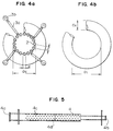
- the slackened inner peripheries of the turns of the tubular film are taken into the gaps between the rod-like rolls 2, as shown in Fig. 4a, so that an extra length for holding the inner diameters of the turns of the tubular film can be increased.
- the heated air is forced to blow through the gaps between the rod-like rolls 2, and accordingly, the inner peripheries of the turns of the slackened tubular film can be smoothly and rapidly heat-shrunk (the heating process will be hereinbelow detailed).
- the tubular film is forced to turn through the rotation of the rod-like rolls about their axes, and accordingly, a large speed difference before and after the heat-shrinkage can be absorbed so that the turning speed can be increased.
- the tubular film 1a has to be turned on the drum while it is guided by the guide pins 3a so that the turns 1b thereof are always shifted in the longitudinal direction (X-X') of the drum as sown in Fig. 2b. That is, the turning of the tubular film by the rod-like rolls 2 rotated about their axes, is made only in the circumferential direction of the drum. Accordingly, should the guide pins 3a be eliminated, the turns of the tubular films would be caught together on the front end of the drum, and accordingly, the tubular film could hardly be spirally turned, smoothly.
- the intervals of the spiral turns 1b of the tubular film on the drum are set by the guide pins so as to define passages for the blown gas as mentioned latter, and accordingly, the guide pins 3a serve as an important role in the heat-treatment of the tubular film, according to the present invention.
- Fig. 6 which shows a typical heat-shrinkage characteristic of a poly-vinylidene chloride group tubular film having a thickness of 50 ⁇ m
- the heating temperature (deg.C) of the tubular film by a hot water bath (or hot oil bath) is taken along the abscissa
- the shrinkage factor of the tubular film in the longitudinal direction of the latter which is obtained by dipping the tubular film in the above-mentioned hot water bath (or hot oil bath) for ten minutes, is taken along the ordinate.
- dots in the figure indicate measured points.
- a tubular film having a bore diameter of, for example, 38 mm in the form of a raw material, and having a heat-shrinkage characteristic as shown in Fig. 6 is inflated so as to have a bore diameter of 41 mm and is curved so as to have turns having an inner diameters of 150 mm
- the inner peripheries of the turns of the tubular film has to fall in a range of 22 % (the drawing rate of the outer peripheries is 22 %) to 35 % (the drawing rate of the outer peripheries is 0 %.
- the inner peripheries of the turns of the tubular film are significantly heated while the tubular film is entirely heated so as to gradually lower the heating temperature from the inner peripheries to the outer peripheries of the turns thereof, and the heat-shrinkage factor of the outer peripheries of the turns should be set to be not higher than at least about 15 %, preferably from 9 to 2 %.
- the temperature of the outer peripheries of the turns of the tubular film is set to be in a range of 80 to 110 deg.C.
- the entire peripheries of the turns of the tubular film can be heated and cooled while the inner peripheries of the turns thereof can be significantly heated.
- the present invention effectively use the features obtained by heat transmission of heat by the gas and the heat-transmission through direct-contact as will be explained below.
- the first feature of the present invention is such that the heat-treatment can be carried out without disturbing the turning condition of the tubular film to be turned by the forced blowing of gas, that is, substantially no buoyancy due to a difference in density between liquid used for the heat-treatment, and a tubular film to be turned, is caused, and further, since gas is used as heat-treatment medium, the frictional resistance at the boundary surface of the tubular film can be neglected substantially.
- the second feature of the present invention is such hat the heat-transmission rate to the tubular film can be adjusted in a wide range by adjusting the blowing speed of the gas. Further, the heat transmission rate can be obtained in a wide range by adjusting the temperature of the gas.
- the third feature of the present invention is such that the heat transmission rate at any of various parts of the tubular film on turning can be adjusted by specifying the blowing direction of gas.
- the fourth feature of the present invention is such that heat-shrinkage, and cooling for curing can be alternately carried out rapidly and smoothly, with no constraint to the dimensional change of the inner peripheries of the turns of the tubular film, by alternately carrying out the heat transmission by gas and the heat transmission by contact.
- heated gas is radially jetted from the inside of the drum as shown in Fig. 3a, and is then blown through the gaps between the rod-like rolls 2 of the drum. Further, as shown in Fig. 3b, the heated air is aerodynamically led around the outer peripheries of the turns 1b of tubular film which is continuously turned through the gaps between the turns 1b of the tubular film.
- the blowing speed of the heated gas is rapidly lowered when it flows from the jetting part to the outer peripheries of the turns of the tubular film, and accordingly, the heat transmission rate toward the tubular film can be high at the inner peripheries of the turns of the tubular film but can be decreased toward the outer peripheries thereof.
- the heat transmission rate toward the tubular film can be high at the inner peripheries of the turns of the tubular film but can be decreased toward the outer peripheries thereof.
- the blowing speed of the heated air jetted from the inside of the drum and having a temperature of 135 deg.C is in a range of 9 to 7 m/sec at the gaps between the rod-like rolls 2, and is in a range of 6 to 3 m/sec at the gaps between the turns 1b of the tubular film, and the convection speed is in a range of 2 to 1 m/sec at the outer peripheries of the turns 1b of the tubular film.
- the inner peripheries of the turns 1b of the tubular film can be heated through contact heat transmission by means of the rod-like rolls 2 of the drum which are nearest to the heated air jetting part so as to be heated at a high heat transmission rate.
- the heating process according to the present invention exhibit a sufficient heating capacity.
- the heated gas from the inside of the drum is encountered to heated gas jetted outside of the drum at the outer peripheries of the turns of the tubular film so that the stream of the heated gas at the outer peripheries of the turns of the tubular film can be rectified, and accordingly, the volume of heat transmission can be adjusted.
- the blowing speed of the heated gas jetted outside of the drum is 0.2 to 0.5 m/sec at the outer peripheries of the turns of the tubular film.
- the temperature and blowing speed of the heated gas jetted from the inside of the drum are preferably higher than those of the heated gas jetted outside of the drum.
- the polyvinylidene chloride group tubular film having a heat-shrinkage characteristic shown in Fig. 6 can be heated by heated gas at a higher limited temperature of about 140 deg.C, and naturally, it can be held without breakage even though the turning of the tubular film is stopped.
- the heating temperature of the tubular film is 80 to 105 deg.C at most.
- the heating temperature according to the present invention is hither than that of the conventional heating process. It is however noted that the temperature of the tubular film has to be decreased sufficiently so as to withstand the pressure and the tension exerted by the outlet side pinch rollers in order to take up the tubular film which has been curved by the heated gas at a relatively high temperature.
- the cooling process according to the present invention subsequent to the above-mentioned heating, can be carried out while a turning condition of the tubular film having been heated and softened is held, and accordingly, the curved tubular film can sufficiently withstand the pressure and the tension exerted by the outlet side pinch rollers.
- cooling gas is radially jetted from the inside of the drum, similar to the heated gas, is then blown through the gaps of the rod-like rolls 2 of the drum, and is then blown through the gaps between the turns of the tubular film so as to be led around the outer peripheries of the turns of the tubular film.
- the blowing speed of the cooling gas is in a range of 2 to 3 m/sec at the gaps between the rod-like rolls.
- the cooling gas jetted from the inside of the drum is preferably encountered by cooling gas jetted outside of the drum at the outer peripheries of the turns of the tubular film turning around the drum so as to enhance the cooling capacity at the outer peripheries of the turns of the tubular film.
- the blowing speed of the cooling gas jetted outside of the drum in a range of, for example, 2 to 1 m/sec.
- a tubular film can be curved while it is turned at a high speed which has not been able to be attained, conventionally.
- air having a relative humidity less than 90 % or steam is used as the gas to be forcibly blown in the present invention.
- the forced flow in the present invention is intended to carry out heat transmission by means of a stream which is forcibly induced.
- the drum in order that the cylindrical film is continuously turned in its turning direction and is taken in to the gaps between the rod-like rolls so as to be smoothly subjected to smooth and rapid heat-shrinkage, the drum preferably satisfies the following formulae: 15 ⁇ L ⁇ 25 0.65 ⁇ d/L ⁇ 0.85 0.70 ⁇ Dc/Di ⁇ 0.85 where d is a diameter (mm) of the rod-like rolls, L is an interaxial distance (mm) of two adjacent rod-like rolls, Di is a diameter (mm) of the turns of the tubular film, and Dc is a diameter (mm) of a circumscribing circle of the drum (refer to Figs. 4a and 4a for details).
- the outlet speed of the tubular film, relative to the inlet speed thereof is desirably set in accordance with a bore diameter or an inner diameter of turns of the tubular film after curving. This can facilitate the operation of the apparatus.
- the above-mentioned factor ⁇ can be calculated from a result of tests under a condition in which the temperature and the blowing volumes of the heated gas are set to be constant, and with the use of this value and the above-mentioned formula, the outlet speed of the tubular film, relative to the inlet speed thereof, can be set with respect to any of several sizes of the tubular film.
- the outlet speed of the tubular film in the case of a tubular film having a heat-shrinkage characteristic as shown in Fig. 6, it is in a range of 0.88 to 0.92.
- the above-mentioned inlet speed Vi is in a range of 7 to 40 m/sec
- the above-mentioned Ca is in a range of 50 to 95 mm
- the above-mentioned Di is in a range of 90 to 300 mm.
- the peripheral speed of the rod-like rolls is preferably adjusted in accordance with a frictional resistance between the outer surface of the tubular film and the outer surfaces of the rod-like rolls. That is, preferably, if the frictional resistance is low, the peripheral speed is adjusted to a high value, but if the frictional resistance is high, the peripheral speed is adjusted to a low value.
- the peripheral speed Vf preferably satisfies the following formula with respect to the inlet speed Vi and the outlet speed Vo: ⁇ Vi ⁇ Vf > Vo It is noted that if Vf > ⁇ Vi , the rubbing of the tubular film turned around the longitudinal axis thereof readily becomes larger, and accordingly, it is not preferably in the case of curving a tubular film on which a trade mark or the like is printed. Further, it Vf ⁇ Vo, the turning of the tubular film readily stagnates so as to be unpreferable.
- the pressure of gas charged in the tubular film is preferably adjusted in order to slightly increase the bore diameter Cr of the tubular film which is a raw material fed out from the inlet side pinch roller, during heating, thereby to preferably turn the tubular film charged with the gas. That is, the pressure of gas charged in the tubular film is preferably adjusted so that the bore diameter Ca of the curved tubular film is set to a value which is 1 to 1.15 times as large as the bore diameter of the tubular film before curving. Further, it is desirable to satisfy the following formula. 1.05 ⁇ Ca/Cr ⁇ 1.12 where Ca is a bore diameter (mm) of the curved tubular film, and Cr is the bore diameter (mm) of the tubular film as a raw material.
- the bore diameter Ca can be adjusted by connecting a compressed gas tube to one end of the tubular film 1d as shown in Fig. 1a upon stopping of the turning of the tubular film, a compressed gas tube is connected to one end of the tubular film, over the extent of the heating length Lh.
- the number of turns of the tubular film on the drum is preferably 3 to 15, but more preferably in a range satisfying the following formula. 6 ⁇ N ⁇ 12 where N is a number of turns of the tubular film. In the case shown in Fig. 2b, the number N is 7.
- the space S between the turns of the tubular film on the drum are preferably 8 to 18 mm, and more preferably in a range satisfying the following formula: 8 ⁇ S ⁇ 15 where S is the space (mm) between the turns of the tubular film turning on the drum (refer to Fig. 3b).
- the outer diameter of a guide pins is preferably 5 to 12 mm.
- the space S is desirably larger than the outer diameter of the guide pins. If the space S would be smaller that the outer diameter of the guide pins, the turns of the tubular film would be caught between the adjacent guide pins, resulting in high possibility of stagnation of turning.
- a lubricant powder onto the tubular film before it is turned, in particular in the case of turning a tubular film which exhibits a viscosity at its outer surface.
- a starch powder or the like can be used as the lubricant powder.
- the heat-treatment for the tubular film can be preferably preformed. That is, in the heat-treatment according to the present invention, if the blowing volume of the heated gas is greater in the front half of the heating length than in the rear half thereof while the blowing volume of the cooling gas is greater in the rear half of the cooling length than in the front half, the heating can be significantly made for the inner peripheries of the turns of the tubular film, and further, the heating for the entire circumference of the turns can be preferably made. Then, the tubular film is cooled so as to be stabilized in order to obtain a curved tubular film. Thus, a ring-like casing film having a smooth external appearance with no shrunk pleats found from the inner peripheries to the outer peripheries of the turns of tubular film can be produced.
- blowing volume can be adjusted by changing the blowing volume of gas jetted from the inside of the drum in the longitudinal direction of the drum, and/or by changing the positions of gas jets and the blowing volume of gas jetted outside of the drum.
- blowing speed of gas to be forcibly blown is preferably 0.05 to 20 m/sec, and more preferably 0.1 to 15 m/sec.
- heating and cooling by gas jetted from the inside of the drum can be adjacent to each other in the longitudinal direction of the drum.
- the length of the drum required for the heat-treatment is satisfactorily set to be less than 1.5 m, and in more preferably to be less than 1.0 m.
- the ratio between the heating length in the longitudinal direction of the drum and the length of the drum is preferably in a ranged of 0.35 to 0.75, and in more preferably in a range which satisfies the following formula: 0.45 ⁇ Lh/Lc ⁇ 0.65 where Lh is a heating length in the axial direction of the drum, and Lc is the length of the drum (heating length + cooling length).
- the temperature of heated gas to be forcibly blown is preferably determined in accordance with the bore diameter of the tubular film, the inner diameter of the turns of the tubular film to be curved, and the heat-shrinkage characteristic of the tubular film as shown in Fig. 6, that is, the temperature range according to the present invention is preferably set so that the heat-shrinkage rate in the longitudinal direction of the tubular film is not less than 5 % but not higher than 60 %.
- the temperature of the cooling gas is preferably set so as to be not less than 0 deg.C but not higher than a temperature at which the heat-shrinkage rate is less than 5 %.
- the temperature of the heated gas is in a range of 100 to 140 deg.C
- the temperature of the cooling gas is in a range of 0 to 40 deg.C.
- the rod-like rolls 2 which are circumferentially arranged so as to constitute the drum as shown in Fig. 1a, are supported at their opposite ends by means of bearings, and are attached at their one end with small diameter gears through which the rod-like rolls 2 can be driven in a bundle by means of a ring gear (which is not shown) within a gear box 10.
- metal bearings may be used as the above-mentioned bearings.
- a small-sized slip bearing or the like made of a composite material composed of heat-resistant and friction-resistant ethylene tetrafluoride resin or the like is preferably used so that the several rod-like rolls 2 can be arranged with relatively small interaxial distances. Further, it is extremely preferable to coat the outer surfaces of the rod-like rolls with ethylene tetrafluoride resin having a heat-resistance and friction-resistance or the like.
- each of the guide pins 3a shown in Fig. 1b is preferably composed of a rotary member having a lubricity which is obtained by ethylene tetrafluoride resin or the like which rotatably fitted on a stationary center shaft.
- the proximal end parts 3b of the guide pins are attached to the support columns 3c arranged in parallel with the longitudinal axis of the drum, and the spaces therebetween can be adjusted in accordance with the bore diameter of the tubular film to be turned.
- the distal ends of the guide pins are as near to the drum as possible, but it is prevented from making contact with the drum.
- a preferable arrangement is such that the distal ends of the guide pins 3a are located in the gaps between the rod-like rolls 2 as shown in Fig. 4a. Should the space between the guide pins 3 and the rod-like rolls be large, the heated and softened tubular film would be possibly caught to the distal ends of the guide pins so as to be broken.
- the inlet side pinch rollers 8 are preferably arranged in the vicinity of the front end of the heating length Lh with a space from the drum. Further, the space between the inlet side pinch rollers 8 and the drum is specifically in a range of 0.5 to 5 m, and more preferably in a range of 2 to 5 m. If the inlet side pinch rollers 8 are preferably incorporated therein with a shift device for shifting the inlet side pinch rollers 8 within the above-mentioned space, the pressure of the gas charged in the tubular film can be finely adjusted.
- the tubular film can be directly taken up from its turning condition so as to be extremely preferable.
- a polyvinylidene chloride group film, a polyamide group film, a polyethylene group film or a polystyrene group film, or the like, or a laminated film thereof can be used.
- a polyvinylidene chloride group tubular film as a raw material having a bore diameter Cr 57 mm, a folding width of 90 mm and a thickness of 50 ⁇ m and having a heat-shrinkage characteristic as shown in Fig.
Abstract

Description
- The present invention relates to a method of manufacturing a ring-like casing film which is obtained by curving a straight tubular film, and also relates to a manufacturing apparatus therefor.
- As a method of manufacturing a ring-like casing film used for producing a ham or a sausage, in which a heat shrinkable thermoplastic tubular film made of polyvinlydene chloride group resin or the like, is curved so as to continuously manufacture a casing film, a method comprising the steps of pinching a tubular film between two pairs of pinch rolls after the tubular film is inflated with gas, and spirally turning the tubular film filled with the gas between the pair of pinch rollers so as to thermally process the tubular film (by heating and cooling or only by heating) has conventionally been well-known.
- For example, DE2322220 discloses a method of and a device for manufacturing a tubular casing film, in which a tubular film charged therein with gas is spirally fed around several rod-like rolls that are arranged around a heating and cooling core roll so as to be rotatable about their axes with no gaps therebetween, along guides provided around the array of the rod-like rolls for spirally feeding the tubular film while the rod-like rolls are rotated about their axes in association with the rotation of the core roll, and accordingly, the tubular film is heated and cooled to be thermally shrunk in order to produce a ring-like casing film having a predetermined radius of curvature. In the above-mentioned device, the tubular film charged with gas is fed to the array of the rod-like rollers through a pair of introducing pinch rollers, the tubular film being heated and cooled for thermal shrinkage while it is spirally fed around the array of the rod-like rolls by means of the guide, and finally the tubular film is taken out from the array of the rod-like rolls through a pair of take-out pinch rollers. Thereafter, the tubular film is sent to a next station for winding up the tubular film and so forth. The heating and cooling of the tubular film is made by thermal conduction from the core roll to the tubular film through the intermediary of the rod-like rolls which make direct contact with the tubular film. In this device, the outer surface of tubular film makes contact with the rod-like rolls which are rotated about their axes so that the frictional resistance therebetween can be reduced, and accordingly, the tubular films can be restrained from wrinkling, thereby it is possible to increase the speed of feeding the tubular film, resulting in enhance of the productivity. However, the area of contact of the outer surface of the tubular film with the rod-like rolls is small, and accordingly, heat conduction between the tubular film and the rod-like rolls is insufficient, resulting in insufficient thermal shrinkage. Thus, this apparatus has offered a disadvantage such that the ring-like film casing has an insufficient curvature.
- Japanese Patent Publication No. 58-23210 discloses a method in which a tubular film is turned around an array of cylindrical rolls which freely rotate while the entire peripheral surface of the tubular film is uniformly heated with the use of a hot water bath (alternatively, liquid bath, heated air, steam or the like), and thereafter, the tubular film is drawn and taken up with the use of a pair of conical pinch rollers. This method is effective for preventing the tubular film from being subjected to thermal strain, and for preventing occurrence of folding and pleating or the like since the entire peripheral surface of the tubular film is uniformly heated.
- However, in this method, should the turning speed of the tubular film which has been spirally wound around the array of rod-like rolls by several turns, be increased, a difference in thermal shrinkage between the inner and outer peripheries of the ring of the tubular film which has been uniformly heated over its entire peripheral surface could hardly occur, and further, the tubular film has a float-up force so that the turning thereof is stagnated. Further, it is likely to cause the tubular film to have insufficient curvature since the tubular film expands in the longitudinal direction thereof. Moreover, should the tubular film be turned while it is heated in the atmosphere of heated air, the tubular film is stagnated around the array of the rod-like rolls, a difficulty would be encountered around the array of the rod-like rolls.
- Japanese Patent Publication NO. 63-56850 discloses a method in which a tubular film is spirally wound on a smooth heating cylindrical roll rotating around the axis thereof so as to be once held thereon, the inner peripheral surface of the tubular film is subjected to contact heating and radiant heating while the outer periphery of the tubular film is heated by forced air blasting from a movable hot air blower, and then, the tubular film is naturally cooled. In this method and the device therefor, it is not required to continuously turn the tubular film on the cylindrical roll, that is, the tubular film can be wound at a comparatively high speed, and further, since the inner peripheral part of the tubular film wound on the cylindrical roll is significantly heated, and accordingly, the tubular film is preferably curved. That is, with the use of such a heat-treatment, the heat-shrinkage at the inner peripheries of turns of the tubular film wound around the cylindrical roll can be sufficient while the heat shrinkage at the outer peripheries thereof can be decreased, and accordingly, the curvature of the thus produced ring-like casing film is still maintained even after the tubular film charged therein with meat is sterilized by heating at about 80 deg.C. thereby it is possible to exhibit an excellent dimensional stability.
- However, since the inner peripheral surfaces of the turns of the tubular film make direct contact with the smooth outer surface of the cylindrical roll during heating, a large frictional resistance is encountered, and accordingly, it is difficult to continuously feed the tubular film at a high speed so as to enhance the productivity. Further, since the inner surfaces of the turns of the tubular film are held by the outer surface of the cylindrical roll, it is likely to represent heat-traces at the boundary of the contact surface of the tubular film.
- As mentioned above, in the conventional methods of continuously curving a tubular film offer disadvantages in a turning process or a heating process of the tubular film although many advantages can be obtained, and accordingly, they are effective for saving labor, but it is not excellent in the productivity, the ability of curving, the external appearance and the like.
- An object of the present invention is to provide a method of and an apparatus for continuously manufacturing a ring-like casing film, which is highly preferable in view of curving the tubular film, and in which the inner peripheral parts of turns of a tubular film is significantly heated so that the thus formed casing film is excellent in dimensional stability, in ability of curving, in the external appearance and the productivity.
- To the end, according to the present invention, there is provided a method of manufacturing a ring-like casing film, comprising the steps of: charging gas into a heat shrinkable thermoplastic tubular film having a predetermined length, spirally feeding the tubular film around an array of rod-like rolls which are arranged with predetermined gaps therebetween and which are rotated about their axes; radially blowing heated gas from the inside of the array of rod-like rolls through the gaps between the rod-like rolls so as to heat and shrink the tubular film while it is spirally fed around the array of rod-like rolls which are rotated about their axes; thereafter, radially blowing cooling air so as to cool the tubular film; taking up the thus shrunk tubular film from the array of rod-like rolls; and discharging the gas from the tubular film.
- Further, according to the present invention, there is provided an apparatus for carrying out the above-mentioned method, that is, for manufacturing a ring-like casing film, comprising means for continuously introducing a tubular film charged therein with gas, an array of rod-like rolls which are arranged circumferentially with gaps therebetween, and which are rotatable about their axes, for winding the introduced tubular film therearound, drive means for rotating the rod-like rolls about their axes; guide means laid around the array of rod-like rolls, for spirally feeding the tubular film around the array of rod-like rolls, heating means provided inside of the array of rod-like rolls, for radially blowing heated gas onto the upstream side of the tubular film spirally wound around the array of rod-like rolls, through gaps between the rod-like rolls; cooling means for radially blowing cooling air onto the downstream side of the tubular film spirally wound around the array of rod-like rolls through the gaps between the rod-like rolls, and means for taking up the heated and shrunk tubular film from the array of rod-like rolls.
- Explanation will be hereinbelow made of preferred embodiments of the present invention with reference to the drawings.
-
- Figs. 1a and 1b are plan and side views schematically illustrating an embodiment of a manufacturing device according to the present invention, in which a side frame is not shown for the sake of brevity;
- Figs. 2a and 2b are side and plan views schematically illustrating a configuration such that a tubular film is fed, being wound around a manufacturing device according to the present invention as shown in Fig. 1;
- Figs. 3a and 3b are side and plan views schematically illustrating a condition in which the tubular film is heat-treated;
- Figs. 4a is a side view showing a configuration in which the inner peripheral part of one of turns of the tubular film and the rod-like rolls are made into contact with each other, and Fig. 4b is a side view illustrating the tubular film which is curved;
- Fig. 5 is a front view schematically illustrating a main heat-treatment device in the above-mentioned embodiment; and
- Fig. 6 is a graph showing a typical characteristic of longitudinal thermal shrinkage of a polyvinylidene chloride group tubular film having a film thickness of 50 µm.
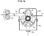
- Referring to Figs. 1a and 1b, a tubular film 1 to be thermally shrunk is wound around a drum composed of several rod-like rolls arranged circumferentially. These rod-like rolls are rotated about their axes in synchronization with one another by means of a drive device (which is not shown). Four
support columns 3c are circumferentially arranged around the drum, and several guide pines 3 are extended toward the drum from the support columns 3. Theseguide pins 3a are provided at predetermined intervals, longitudinal of thesupport columns 3c by means ofproximal end parts 3b which are rotatably journalled to thesupport columns 3c. Theseguide pins 3a hold turns of the tubular film circumferentially wound around the drum so that thetubular film 1a inflated with gas charged therein is spirally fed along the peripheral surface of the drum. Figs. 2a and 2b shows details of the configuration of the spiral feed of the tubular film. - Further, referring to Figs. 1a and 1b, a pair of inlet side pinch rollers 8 are provided below the drum and spaced from the outer periphery of the drum, and a pair of outlet side pinch rollers are provided above the drum and spaced from the outer periphery of the drum.
- With this arrangement, the
tubular film 1a inflated with gas is fed onto the drum which is constituted by a circumferential array of the rod-like rolls 2, and is led around the drum through respective rotations of the rod-like rolls 2 about their axes. Then, thetubular film 1a is spirally fed on the outer peripheral surface of the drum, being guided by theguide pins 3a, and finally, it is taken out from the drum by means of the outletside pinch rollers 9. Thereafter, thetubular film 1a is fed to a next process station such as a wind-up station. As clearly shown in Figs. 1a and 1b, the drum and the outletside pinch rollers 9 are arranged inside of a support frame for the drum, but the inlet side pinch rollers 8 are arranged outside of the support frame. - The drum is incorporated therein which a main heat-treatment device 4, and
auxiliary heating devices 5a, 5b are attached toheating housings tubular film 1a led into by the inlet side pinch rollers 8 is heated for shrinkage so as to be curved by the lower half Lh of the drum, that is, on the upstream side thereof in the feed direction of the tubular film, and then is cooled and cured by the top part of the drum, that is, in a cooling range upstream thereof in the feed direction of the tubular film. Thereafter, the tubular film is taken up from the drum by means of the outletside pinch rollers 9. - The main heat-treatment device 4, as shown in detail in Fig. 5, is composed of a gas feed pipe having a heated
gas inlet port 4a at one end, a cooling gas inlet port at the other end, and an outer peripheral wall formed therein perforations. The inside of the gas feed pipe is partitioned into a heated gas chamber and a cooling gas chamber by means of abarrier 4d. Accordingly, pressurized gas generated from blowers or the like, is introduced into both gas chambers through theinlet ports perforations 4c in the outer peripheral wall of the gas feed pipe 4. Thus, the jetted gas is blown through the gaps between the rod-like rolls 2 constituting the drum so as to heat and cool theturns 1b of thetubular film 1a which is spirally fed along the outer peripheral surface of the drum at their inner peripheries. It goes without saying that the structure of the main heat-treatment device according to the present invention should not be limited to the above-mentioned arrangement, but it may have any of other arrangements. For example, two gas feed pipes independent from each other may be used for heated gas and cooling gas, respectively. Further, theperforations 4c may have different sizes and may be distributed variously so as to adjust the jetting speed and blowing volume of gas along the longitudinal direction in which the spiral turns 1b of the tubular film are advanced. - Further, conveniently, the above-mentioned blower incorporates an electric gas heating device so as to generate the heated gas in order to facilitate the adjustment of the temperature of gas, and the volume of gas.
- Further, the auxiliary heating device is composed of a
perforated panel 5b, that is, diffusing panel attached to the lower part of aheating housing 6a, extending substantially over the lower half of the drum, that is, in a range of a heating length Lh. Theperforated panel 5b defines an annular heated gas chamber which surround the one half of the entire periphery of the drum, and heated gas is introduced into the annular heated gas chamber from an external heating device through an inlet port 5a, and is then jetted though heated air jetting holes 5c toward the outer peripheral surface of the drum so as to heat theturns 1b of the tubular film which is spirally fed on the outer peripheral surface of the drum at their outer peripheries. It is noted that the above-mentioned heating housing composed of a onehalf part 6a made of steel, and an openableupper housing 6b formed of, for example, transparent heat-resistant resin such as polycarbonate resin or polyimide resin and combined with the onehalf part 6a, is preferable and convenient since the manipulatable on the drum can be enhanced and the spiral turning of the tubular film thereon can be checked. - Further, the above-mentioned auxiliary cooling device as shown in Fig. 1a, may be composed of a plurality of blowers 7 attached to a support frame in a range of cooling length (Lc - Lh). It is desirable to attach the blowers 7 to the support frame so that the jetted cooling gas is blown onto the outer peripheries of the turns of the tubular film, and the attachment positions of the blowers 7 are near to the rear end of the cooling length as shown in Fig. 1a. It is noted that the temperature of atmospheric air at the inlet side of the blowers is desirably in a range of 0 deg.C to a temperature lower than a heat-shrinkage temperature of the tubular film in the case of using the above-mentioned blower arrangement.
- Explanation will hereinbelow be made of the operation of the above-mentioned apparatus according to the present invention.
- The
tubular film 1a which is inflated so as to have a bore diameter of, for example, 41 mm is fed by the inlet side pinch rollers 8 onto the outer peripheral surface of the drum in the form of a circumferential array of the rod-like rolls 2 which are rotated about their axes, and accordingly, thetubular film 1a is wound on the peripheral surface of the drum while it is spirally fed thereon by the rotation of the rod-like rolls 2 and the action by theguide pines 3a. Further, the inner peripheries of theturns 1b of thetubular film 1a are heated by heated gas blown from the heated air chamber of the main heat-treatment device through theperforations 4c, and further, the outer peripheries of theturns 1b of the tubular film are heated by heated gas blown from the jet holes 5a of the auxiliary heating device, on the upstream side as views in the advance direction of theturns 1b of the tubular film. Then, the inner peripheries of theturns 1c of the tubular film are cooled by cooling gas jetted from the cooling gas chamber through theperforations 4c while the outer peripheries of theturns 1c of the tubular film are cooled by cooling air blown from the auxiliary cooling devices 7 so as to from a ring-like casing film 1c which is then taken up from the drum by the outletside pinch rollers 9, and from which charged gas is then discharged before it is fed as aprimary product 1d into a next process station such as a wind-up station. - In the above-mentioned case, if the tubular film is curved so that the inner diameter of the turns of the tubular film becomes 150 mm, the inner peripheries of the turns of the tubular film should be shrunk in a range of 22 % (drawing rate of outer peripheries is 22 %) to 35 % (drawing rate of outer peripheries is 0 %). Further, if the tubular film is fed out at a feed speed of 10 m/min, the drawing speed of the inner peripheries of the turns of the curved tubular film should be set in a range of 7 to 8 m/min. At this time, a speed difference before and after the heat shrinkage of the inner peripheries of the turns of the tubular film falls in a range of 2 to 3 m/min. Further, when the turning speed of the tubular film is increased, the above-mentioned speed difference becomes larger. Namely, if the tubular film is fed at a speed of 32 m/min on the inlet side, the speed on the outlet side becomes 25 to 21 m/min, and accordingly, the above-mentioned speed difference becomes 7 to 11 m/min. Further, the speed difference can be determined by a difference between the peripheral speeds of the
pinch rollers 8, 9 in pairs in which each pair of rollers are combined in parallel with each other in the arrangement according to the present invention. - The allowable capability of the above-mentioned speed difference is important in the above-mentioned process of spirally winding the tubular film. That is, there is raised such a problem that how the inner peripheries of the turns of the tubular film which causes a large speed difference before and after the heat-shrinkage when the turning speed of the tubular film is increased are held and wound on the outer peripheral surface of the drum, and how this speed difference is absorbed.
- In a conventional process in which a tubular film wound by several turns by means of a smooth cylindrical roller which is driven by a drive shaft, the frictional resistance between the inner peripheries of the turns of the tubular film is large so that the allowable speed difference as mentioned above is small so that the inlet side speed of the tubular film is 10 m/min. at most. That is, in this conventional process, the tubular film is merely wound on the cylindrical roll on which it is spirally turned, and accordingly, the heat-shrinkage of the inner peripheries of the turns of the tubular film is hindered by the frictional resistance between the tubular film and the outer surface of the roller. Thus, the smooth and rapid heat-shrinkage can hardly be made. Further, when the heat-shrinkage is delayed, the inner peripheries of extra turns of the tubular film cannot be relieved on the cylindrical roller, and as a result, the inner peripheries of the turns of the tubular film is folded and pleated.
- Meanwhile, in the above-mentioned arrangement of the apparatus according to the present invention, the allowable speed difference during spiral turning of the tubular film is relatively high. Even though the tubular film is fed out at a speed of, for example, 32m/min., the inner peripheries of the turns of the tubular film can be smoothly and rapidly heat-shrunk, and the above-mentioned speed difference can be absorbed well. The reason why it is so will be explained below:
- That is, since the rod-
like rolls 2 are rotated about their axes so as to feed the tubular film wound around the drum in its longitudinal direction, the tubular film wound on the drum by several turns can be spirally fed by turning with no hindrance, and accordingly, even though the rod-like rolls 2 are rotated at a peripheral speed higher than the outlet side speed of the inner peripheries of the turns of the curved tubular film (that is, higher than the peripheral speed of the outlet side of the pinch rollers), the inner peripheries of the turns of the curved tubular film having an increased friction resistance due to heating, can be excessively fed so as to be slackened in the turning direction thereof. Further, the slackened inner peripheries of the turns of the tubular film are taken into the gaps between the rod-like rolls 2, as shown in Fig. 4a, so that an extra length for holding the inner diameters of the turns of the tubular film can be increased. With this arrangement, according to the present invention, the heated air is forced to blow through the gaps between the rod-like rolls 2, and accordingly, the inner peripheries of the turns of the slackened tubular film can be smoothly and rapidly heat-shrunk (the heating process will be hereinbelow detailed). - It is noted that even though the rod-
like rolls 2 are rotated at a peripheral speed which is higher than the outlet speed of the inner peripheries of the turns of the curved tubular film during cooling subsequent to the heating, since the rod-like rolls 2 slips at the inner peripheries of the turns of the tubular film having a frictional resistance which is deceased as it is cooled, it is possible to prevent the inner peripheries of the turns of the tubular film from being excessively fed as during the heating. - As mentioned above, in the process of turning or winding the tubular film, according to the present invention, the tubular film is forced to turn through the rotation of the rod-like rolls about their axes, and accordingly, a large speed difference before and after the heat-shrinkage can be absorbed so that the turning speed can be increased.
- Further, in the process of turning the tubular film, according to the present invention, the
tubular film 1a has to be turned on the drum while it is guided by the guide pins 3a so that theturns 1b thereof are always shifted in the longitudinal direction (X-X') of the drum as sown in Fig. 2b. That is, the turning of the tubular film by the rod-like rolls 2 rotated about their axes, is made only in the circumferential direction of the drum. Accordingly, should the guide pins 3a be eliminated, the turns of the tubular films would be caught together on the front end of the drum, and accordingly, the tubular film could hardly be spirally turned, smoothly. Further, the intervals of the spiral turns 1b of the tubular film on the drum are set by the guide pins so as to define passages for the blown gas as mentioned latter, and accordingly, the guide pins 3a serve as an important role in the heat-treatment of the tubular film, according to the present invention. - Next, explanation will be made of a heat-treatment process for the tubular film according to the present invention. Referring to Fig. 6 which shows a typical heat-shrinkage characteristic of a poly-vinylidene chloride group tubular film having a thickness of 50 µm, the heating temperature (deg.C) of the tubular film by a hot water bath (or hot oil bath) is taken along the abscissa, and the shrinkage factor of the tubular film in the longitudinal direction of the latter, which is obtained by dipping the tubular film in the above-mentioned hot water bath (or hot oil bath) for ten minutes, is taken along the ordinate. It is noted that dots in the figure indicate measured points.
- In order that a tubular film having a bore diameter of, for example, 38 mm in the form of a raw material, and having a heat-shrinkage characteristic as shown in Fig. 6, is inflated so as to have a bore diameter of 41 mm and is curved so as to have turns having an inner diameters of 150 mm, the inner peripheries of the turns of the tubular film has to fall in a range of 22 % (the drawing rate of the outer peripheries is 22 %) to 35 % (the drawing rate of the outer peripheries is 0 %. Accordingly, in order to heat-shrink the inner peripheries of the turns of the above-mentioned polyvinylidene chloride group tubular film in the above-mentioned range, it is necessary to heat at least the inner peripheries of the turns of the tubular film in a range of 90 to 120 deg.C. However, should only the outer peripheries of turns of the tubular film are heated while the outer peripheries thereof are not heated, the heat-shrinkage ability inherent to the tubular film remains at the outer peripheries of the turns so that the dimensions of the tubular film after curving becomes unstable. If a ring-like casing film produced from such a tubular film, is subjected to heat-sterilization at about 80 deg.C after meat is charged therein, the curvature of the outer peripheries of the turns is likely to be relieved since the heat-shrinkage ability of the outer peripheries of the turns is large. Accordingly, in order to produce a ring-like casing film having an excellent dimensional stability after curving, it is required that the inner peripheries of the turns of the tubular film are significantly heated while the tubular film is entirely heated so as to gradually lower the heating temperature from the inner peripheries to the outer peripheries of the turns thereof, and the heat-shrinkage factor of the outer peripheries of the turns should be set to be not higher than at least about 15 %, preferably from 9 to 2 %. At this time, the temperature of the outer peripheries of the turns of the tubular film is set to be in a range of 80 to 110 deg.C.
- In the heat-treatment process for the tubular film, according to the present invention, the entire peripheries of the turns of the tubular film can be heated and cooled while the inner peripheries of the turns thereof can be significantly heated. The present invention effectively use the features obtained by heat transmission of heat by the gas and the heat-transmission through direct-contact as will be explained below.
- The first feature of the present invention is such that the heat-treatment can be carried out without disturbing the turning condition of the tubular film to be turned by the forced blowing of gas, that is, substantially no buoyancy due to a difference in density between liquid used for the heat-treatment, and a tubular film to be turned, is caused, and further, since gas is used as heat-treatment medium, the frictional resistance at the boundary surface of the tubular film can be neglected substantially.
- The second feature of the present invention is such hat the heat-transmission rate to the tubular film can be adjusted in a wide range by adjusting the blowing speed of the gas. Further, the heat transmission rate can be obtained in a wide range by adjusting the temperature of the gas.
- The third feature of the present invention is such that the heat transmission rate at any of various parts of the tubular film on turning can be adjusted by specifying the blowing direction of gas.
- Further, with the combination of the thermal transmission by contact through the rod-like rolls as stated in the above-mentioned feature, the following feature can be obtained further:
- The fourth feature of the present invention is such that heat-shrinkage, and cooling for curing can be alternately carried out rapidly and smoothly, with no constraint to the dimensional change of the inner peripheries of the turns of the tubular film, by alternately carrying out the heat transmission by gas and the heat transmission by contact.
- In the heating process utilizing the above-mentioned features of the present invention, heated gas is radially jetted from the inside of the drum as shown in Fig. 3a, and is then blown through the gaps between the rod-
like rolls 2 of the drum. Further, as shown in Fig. 3b, the heated air is aerodynamically led around the outer peripheries of theturns 1b of tubular film which is continuously turned through the gaps between theturns 1b of the tubular film. At this time, the blowing speed of the heated gas is rapidly lowered when it flows from the jetting part to the outer peripheries of the turns of the tubular film, and accordingly, the heat transmission rate toward the tubular film can be high at the inner peripheries of the turns of the tubular film but can be decreased toward the outer peripheries thereof. For example, in the present invention, if a tubular film which is inflated so as to have a bore diameter of 41 mm and which has a heat-shrinkage characteristic shown in Fig. 6, is turned around a drum whose a circumscribing circle has a diameter of 120 mm, so as to be curved into turns having an inner diameter of 150 mm, the blowing speed of the heated air jetted from the inside of the drum and having a temperature of 135 deg.C is in a range of 9 to 7 m/sec at the gaps between the rod-like rolls 2, and is in a range of 6 to 3 m/sec at the gaps between theturns 1b of the tubular film, and the convection speed is in a range of 2 to 1 m/sec at the outer peripheries of theturns 1b of the tubular film. Further, in the heating process according to the present invention, the inner peripheries of theturns 1b of the tubular film can be heated through contact heat transmission by means of the rod-like rolls 2 of the drum which are nearest to the heated air jetting part so as to be heated at a high heat transmission rate. - In a curved condition of the tubular film which has been heated as mentioned above, if the above-mentioned polyvinylidene chloride group tubular film is fed out at a speed of, for example, 32 m/min, slight pleats could be sometimes found in a portion from the inner periphery to side surfaces of the leading end part of the first turn of the tubular film on the drum, but the pleats are completely eliminated therefrom in the vicinity of the trailing end part of the first turn thereof. Thus, the tubular element is completely curved at the second or third turn of the tubular film.
- Further, the heating process according to the present invention exhibit a sufficient heating capacity. However, more preferably, the heated gas from the inside of the drum is encountered to heated gas jetted outside of the drum at the outer peripheries of the turns of the tubular film so that the stream of the heated gas at the outer peripheries of the turns of the tubular film can be rectified, and accordingly, the volume of heat transmission can be adjusted. For example, the blowing speed of the heated gas jetted outside of the drum is 0.2 to 0.5 m/sec at the outer peripheries of the turns of the tubular film. Further, the temperature and blowing speed of the heated gas jetted from the inside of the drum are preferably higher than those of the heated gas jetted outside of the drum.
- Further, according to the present invention, the polyvinylidene chloride group tubular film having a heat-shrinkage characteristic shown in Fig. 6 can be heated by heated gas at a higher limited temperature of about 140 deg.C, and naturally, it can be held without breakage even though the turning of the tubular film is stopped. On the contrary, in a prior art process which has relied upon heating by contact or heating by a hot water bath, the heating temperature of the tubular film is 80 to 105 deg.C at most. Thus, the heating temperature according to the present invention is hither than that of the conventional heating process. It is however noted that the temperature of the tubular film has to be decreased sufficiently so as to withstand the pressure and the tension exerted by the outlet side pinch rollers in order to take up the tubular film which has been curved by the heated gas at a relatively high temperature.
- It is noted that the cooling process according to the present invention, subsequent to the above-mentioned heating, can be carried out while a turning condition of the tubular film having been heated and softened is held, and accordingly, the curved tubular film can sufficiently withstand the pressure and the tension exerted by the outlet side pinch rollers.
- In the cooling process according to the present invention, cooling gas is radially jetted from the inside of the drum, similar to the heated gas, is then blown through the gaps of the rod-
like rolls 2 of the drum, and is then blown through the gaps between the turns of the tubular film so as to be led around the outer peripheries of the turns of the tubular film. For example, the blowing speed of the cooling gas is in a range of 2 to 3 m/sec at the gaps between the rod-like rolls. - In the cooling process according to the present invention, the cooling gas jetted from the inside of the drum is preferably encountered by cooling gas jetted outside of the drum at the outer peripheries of the turns of the tubular film turning around the drum so as to enhance the cooling capacity at the outer peripheries of the turns of the tubular film. The blowing speed of the cooling gas jetted outside of the drum in a range of, for example, 2 to 1 m/sec.
- As mentioned above, according to the present invention, with the use of the process of turning a tubular film and the process of heat-treating a tubular film, as mentioned above, a tubular film can be curved while it is turned at a high speed which has not been able to be attained, conventionally.
- It is noted that air having a relative humidity less than 90 % or steam is used as the gas to be forcibly blown in the present invention. The forced flow in the present invention is intended to carry out heat transmission by means of a stream which is forcibly induced.
- In the present invention, in order that the cylindrical film is continuously turned in its turning direction and is taken in to the gaps between the rod-like rolls so as to be smoothly subjected to smooth and rapid heat-shrinkage, the drum preferably satisfies the following formulae:

- Further, in the method according to the present invention, in order to produce a ring-like casing film having a stable inner diameter of turns, the outlet speed of the tubular film, relative to the inlet speed thereof, is desirably set in accordance with a bore diameter or an inner diameter of turns of the tubular film after curving. This can facilitate the operation of the apparatus. According to the present invention, the outlet speed of the tubular film, relative to the inlet speed thereof, is set with reference to the following formula:

- Further, in order to stably turn the tubular film on the drum, the peripheral speed of the rod-like rolls is preferably adjusted in accordance with a frictional resistance between the outer surface of the tubular film and the outer surfaces of the rod-like rolls. That is, preferably, if the frictional resistance is low, the peripheral speed is adjusted to a high value, but if the frictional resistance is high, the peripheral speed is adjusted to a low value. The peripheral speed Vf preferably satisfies the following formula with respect to the inlet speed Vi and the outlet speed Vo:


- Further, in the method according to the present invention, the pressure of gas charged in the tubular film is preferably adjusted in order to slightly increase the bore diameter Cr of the tubular film which is a raw material fed out from the inlet side pinch roller, during heating, thereby to preferably turn the tubular film charged with the gas. That is, the pressure of gas charged in the tubular film is preferably adjusted so that the bore diameter Ca of the curved tubular film is set to a value which is 1 to 1.15 times as large as the bore diameter of the tubular film before curving. Further, it is desirable to satisfy the following formula.

- It is noted that the bore diameter Ca can be adjusted by connecting a compressed gas tube to one end of the
tubular film 1d as shown in Fig. 1a upon stopping of the turning of the tubular film, a compressed gas tube is connected to one end of the tubular film, over the extent of the heating length Lh. - Further, the method according to the present invention, the number of turns of the tubular film on the drum is preferably 3 to 15, but more preferably in a range satisfying the following formula.

- Further, the method according to the present invention, the space S between the turns of the tubular film on the drum are preferably 8 to 18 mm, and more preferably in a range satisfying the following formula:

- It is noted that the outer diameter of a guide pins is preferably 5 to 12 mm. Further, the space S is desirably larger than the outer diameter of the guide pins. If the space S would be smaller that the outer diameter of the guide pins, the turns of the tubular film would be caught between the adjacent guide pins, resulting in high possibility of stagnation of turning.
- Further, in the method according to the present invention, it is preferable to previously spray a lubricant powder onto the tubular film before it is turned, in particular in the case of turning a tubular film which exhibits a viscosity at its outer surface. It is noted that those produced from a starch powder or the like can be used as the lubricant powder.
- In the method according to the present invention, if the blowing volume of gas forcibly blown as mentioned above, is adjusted along the longitudinal axis of the drum, the heat-treatment for the tubular film can be preferably preformed. That is, in the heat-treatment according to the present invention, if the blowing volume of the heated gas is greater in the front half of the heating length than in the rear half thereof while the blowing volume of the cooling gas is greater in the rear half of the cooling length than in the front half, the heating can be significantly made for the inner peripheries of the turns of the tubular film, and further, the heating for the entire circumference of the turns can be preferably made. Then, the tubular film is cooled so as to be stabilized in order to obtain a curved tubular film. Thus, a ring-like casing film having a smooth external appearance with no shrunk pleats found from the inner peripheries to the outer peripheries of the turns of tubular film can be produced.
- It is noted that the above-mentioned blowing volume can be adjusted by changing the blowing volume of gas jetted from the inside of the drum in the longitudinal direction of the drum, and/or by changing the positions of gas jets and the blowing volume of gas jetted outside of the drum.
- Further, the blowing speed of gas to be forcibly blown, is preferably 0.05 to 20 m/sec, and more preferably 0.1 to 15 m/sec.
- Further, in the method according to the present invention, heating and cooling by gas jetted from the inside of the drum can be adjacent to each other in the longitudinal direction of the drum. Further, the length of the drum required for the heat-treatment is satisfactorily set to be less than 1.5 m, and in more preferably to be less than 1.0 m. At this time, the ratio between the heating length in the longitudinal direction of the drum and the length of the drum (heating-length + cooling length) is preferably in a ranged of 0.35 to 0.75, and in more preferably in a range which satisfies the following formula:

- Further, in the method according to the present invention, the temperature of heated gas to be forcibly blown, is preferably determined in accordance with the bore diameter of the tubular film, the inner diameter of the turns of the tubular film to be curved, and the heat-shrinkage characteristic of the tubular film as shown in Fig. 6, that is, the temperature range according to the present invention is preferably set so that the heat-shrinkage rate in the longitudinal direction of the tubular film is not less than 5 % but not higher than 60 %. Further, the temperature of the cooling gas is preferably set so as to be not less than 0 deg.C but not higher than a temperature at which the heat-shrinkage rate is less than 5 %. Specifically, in the case of a polyvinylidene chloride group tubular film having a heat-shrinkage characteristic as shown in Fig. 6, the temperature of the heated gas is in a range of 100 to 140 deg.C, and the temperature of the cooling gas is in a range of 0 to 40 deg.C.
- In the apparatus according to the present invention, the rod-
like rolls 2 which are circumferentially arranged so as to constitute the drum as shown in Fig. 1a, are supported at their opposite ends by means of bearings, and are attached at their one end with small diameter gears through which the rod-like rolls 2 can be driven in a bundle by means of a ring gear (which is not shown) within agear box 10. It is noted that metal bearings may be used as the above-mentioned bearings. However, a small-sized slip bearing or the like made of a composite material composed of heat-resistant and friction-resistant ethylene tetrafluoride resin or the like is preferably used so that the several rod-like rolls 2 can be arranged with relatively small interaxial distances. Further, it is extremely preferable to coat the outer surfaces of the rod-like rolls with ethylene tetrafluoride resin having a heat-resistance and friction-resistance or the like. - Further, in the apparatus according to the present invention, each of the guide pins 3a shown in Fig. 1b, is preferably composed of a rotary member having a lubricity which is obtained by ethylene tetrafluoride resin or the like which rotatably fitted on a stationary center shaft. Further, the
proximal end parts 3b of the guide pins are attached to thesupport columns 3c arranged in parallel with the longitudinal axis of the drum, and the spaces therebetween can be adjusted in accordance with the bore diameter of the tubular film to be turned. Further, the distal ends of the guide pins are as near to the drum as possible, but it is prevented from making contact with the drum. For example, a preferable arrangement is such that the distal ends of the guide pins 3a are located in the gaps between the rod-like rolls 2 as shown in Fig. 4a. Should the space between the guide pins 3 and the rod-like rolls be large, the heated and softened tubular film would be possibly caught to the distal ends of the guide pins so as to be broken. - In the apparatus according to the present invention, the inlet side pinch rollers 8 are preferably arranged in the vicinity of the front end of the heating length Lh with a space from the drum. Further, the space between the inlet side pinch rollers 8 and the drum is specifically in a range of 0.5 to 5 m, and more preferably in a range of 2 to 5 m. If the inlet side pinch rollers 8 are preferably incorporated therein with a shift device for shifting the inlet side pinch rollers 8 within the above-mentioned space, the pressure of the gas charged in the tubular film can be finely adjusted.
- In the apparatus according to the present invention, if the outlet
side pinch rollers 9 are arranged adjacent to the rear end of the cooling length of the drum as shown in Fig. 1a, the tubular film can be directly taken up from its turning condition so as to be extremely preferable. - It is noted that a polyvinylidene chloride group film, a polyamide group film, a polyethylene group film or a polystyrene group film, or the like, or a laminated film thereof can be used.
- The present invention will be explained in detail in the form of the reference examples, but the present invention should not limit to these reference examples. Further, the several conditions of the reference examples are shown in Table I.
- A polyvinylidene chloride group tubular film as a raw material having a bore diameter Cr = 57 mm, a folding width of 90 mm and a thickness of 50 µm and having a heat-shrinkage characteristic as shown in Fig. 6 was inflated with compressed air at a pressure of 0.09 kg/cm2, and was spirally turned around the drum, having a circumscribing circle of a diameter Dc = 210 mm, at an inlet speed of 32.0 m/min, at a peripheral speed of the rod-like rolls of 25.6 m/min and an outlet speed of 22.5 m/sec, as shown by the reference example 1 in Table 1, was heated by heated gas at a maximum temperature of 135 deg.C, and was subsequently cooled by cooling gas at a temperature of 23 deg.C, thereby a ring-like casing film was produced with the use of the apparatus as shown in Fig. 1a. When the thus obtained ring-like casing film was inflated by charging compressed air at a pressure of 0.14 kg/cm2 thereinto, completely no pleats were found in the portions extending from the inner peripheries to the outer peripheries of the turns of the curved tubular film having a bore diameter Ca = 62 mm, and the inner diameter Di = 250 mm of the turns. When the film was heated in a hot water bath at a temperature of 82 deg.C for 60 min., the shrinkage factor was 0.5 % at the inner peripheries of the turns, and 5.5 % at the outer peripheries of the turns.
- A polyvinylidene chloride group tubular film as a raw material having a bore diameter Cr = 51 mm, a folding width of 80 mm and a thickness of 50 µm and having a heat-shrinkage characteristic as shown in Fig. 6 was inflated with compressed air at a pressure of 0.10 kg/cm2, and was spirally turned around the drum the same as that of the reference example 1 in table 1, at an inlet speed of 32.0 m/min, at a peripheral speed of the rod-like rolls of 26.0 m/min and an outlet speed of 23.0 m/sec, was heated by heated gas at a temperature of 135 deg.C, and was subsequently cooled by cooling gas at a temperature of 23 deg.C, thereby a ring-like casing film was produced. When the thus obtained ring-like casing film was inflated by charging compressed air at a pressure of 0.16 kg/cm2 thereinto, completely no pleats were found in the portions extending from the inner peripheries to the outer peripheries of the turns of the curved tubular film having a bore diameter Ca = 55 mm, and the inner diameter Di = 251 mm of the turns. When the film was heated in a hot water bath at a temperature of 82 deg.C for 60 min., the shrinkage factor was 0.3 % at the inner peripheries of the turns, and 8.0 % at the outer peripheries of the turns.
- A polyvinylidene chloride group tubular film as a raw material having a bore diameter Cr = 45 mm, a folding width of 70 mm and a thickness of 50 µm and having a heat-shrinkage characteristic as shown in Fig. 6 was inflated with compressed air at a pressure of 0.12 kg/cm2, and was spirally turned around the drum the same as that of the reference example 1 in table 1, at an inlet speed of 32.0 m/min, at a peripheral speed of the rod-like rolls of 26.7 m/min and an outlet speed of 23.5 m/sec, was heated by heated gas at a temperature of 135 deg.C, and was subsequently cooled by cooling gas at a temperature of 23 deg.C, thereby a ring-like casing film was produced. When the thus obtained ring-like casing film was inflated by charging compressed air at a pressure of 0.18 kg/cm2 thereinto, completely no pleats were found in the portions extending from the inner peripheries to the outer peripheries of the turns of the curved tubular film having a bore diameter Ca = 49 mm, and the inner diameter Di = 249 mm of the turns. When the film was heated in a hot water bath at a temperature of 82 deg.C for 60 min., the shrinkage factor was 0 % at the inner peripheries of the turns, and 3.0 % at the outer peripheries of the turns.
- A polyvinylidene chloride group tubular film as a raw material having a bore diameter Cr = 41 mm, a folding width of 65 mm and a thickness of 50 µm and having a heat-shrinkage characteristic as shown in Fig. 6 was inflated with compressed air at a pressure of 0.09 kg/cm2, and was spirally turned around the drum the same as that of the reference example 1 in table 1, at an inlet speed of 32.0 m/min, at a peripheral speed of the rod-like rolls of 27.1 m/min and an outlet speed of 23.8 m/sec, was heated by heated gas at a temperature of 135 deg.C, and was subsequently cooled by cooling gas at a temperature of 23 deg.C, thereby a ring-like casing film was produced. When the thus obtained ring-like casing film was inflated by charging compressed air at a pressure of 0.20 kg/cm2 thereinto, completely no pleats were found in the portions extending from the inner peripheries to the outer peripheries of the turns of the curved tubular film having a bore diameter Ca = 45 mm, and the inner diameter Di = 249 mm of the turns. When the film was heated in a hot water bath at a temperature of 82 deg.C for 60 min., the shrinkage factor was 0.5 % at the inner peripheries of the turns, and 5.0 % at the outer peripheries of the turns.
- A polyvinylidene chloride group tubular film as a raw material having a bore diameter Cr = 38 mm, a folding width of 60 mm and a thickness of 50 µm and having a heat-shrinkage characteristic as shown in Fig. 6 was inflated with compressed air at a pressure of 0.13 kg/cm2, and was spirally turned around the drum, having a circumscribing circle of a diameter Dc = 120 mm, at an inlet speed of 32.0 m/min, at a peripheral speed of the rod-like rolls of 22.9 m/min and an outlet speed of 22.1 m/sec, as shown by the reference example 1 in Table 1, was heated by heated gas at a maximum temperature of 135 deg.C, and was subsequently cooled by cooling gas at a temperature of 23 deg.C, thereby a ring-like casing film was produced with the use of the apparatus as shown in Fig. 1a. When the thus obtained ring-like casing film was inflated by charging compressed air at a pressure of 0.21 kg/cm2 thereinto, completely no pleats were found in the portions extending from the inner peripheries to the outer peripheries of the turns of the curved tubular film having a bore diameter Ca = 41 mm, and the inner diameter Di = 150 mm of the turns. When the film was heated in a hot water bath at a temperature of 82 deg.C for 60 min., the shrinkage factor was 0 % at the inner peripheries of the turns, and 5 % at the outer peripheries of the turns.
- A polyvinylidene chloride group tubular film as a raw material having a bore diameter Cr = 46 mm, a folding width of 75 mm and a thickness of 50 µm and having a heat-shrinkage characteristic as shown in Fig. 6 was inflated with compressed air at a pressure of 0.11 kg/cm2, and was spirally turned around the drum the same as that of the reference example 5 in table 1, at an inlet speed of 32.0 m/min, at a peripheral speed of the rod-like rolls of 23.6 m/min and an outlet speed of 20.8 m/sec, was heated by heated gas at a temperature of 135 deg.C, and was subsequently cooled by cooling gas at a temperature of 23 deg.C, thereby a ring-like casing film was produced. When the thus obtained ring-like casing film was inflated by charging compressed air at a pressure of 0.17 kg/cm2 thereinto, completely no pleats were found in the portions extending from the inner peripheries to the outer peripheries of the turns of the curved tubular film having a bore diameter Ca = 52 mm, and the inner diameter Di = 148 mm of the turns. When the film was heated in a hot water bath at a temperature of 82 deg.C for 60 min., the shrinkage factor was 0.5 % at the inner peripheries of the turns, and 4.5 % at the outer peripheries of the turns.
- A polyvinylidene chloride group tubular film as a raw material having a bore diameter Cr = 35 mm, a folding width of 55 mm and a thickness of 50 µm and having a heat-shrinkage characteristic as shown in Fig. 6 was inflated with compressed air at a pressure of 0.14 kg/cm2, and was spirally turned around the drum the same as that of the reference example 5 in table 1, at an inlet speed of 32.0 m/min, at a peripheral speed of the rod-like rolls of 25.2 m/min and an outlet speed of 22.2 m/sec, was heated by heated gas at a temperature of 135 deg.C, and was subsequently cooled by cooling gas at a temperature of 23 deg.C, thereby a ring-like casing film was produced. When the thus obtained ring-like casing film was inflated by charging compressed air at a pressure of 0.23 kg/cm2 thereinto, completely no pleats were found in the portions extending from the inner peripheries to the outer peripheries of the turns of the curved tubular film having a bore diameter Ca = 39 mm, and the inner diameter Di = 145 mm of the turns. When the film was heated in a hot water bath at a temperature of 82 deg.C for 60 min., the shrinkage factor was 0 % at the inner peripheries of the turns, and 5.0 % at the outer peripheries of the turns.
- A polyvinylidene chloride group tubular film as a raw material having a bore diameter Cr = 35 mm, a folding width of 55 mm and a thickness of 50 µm and having a heat-shrinkage characteristic as shown in Fig. 6 was inflated with compressed air at a pressure of 0.14 kg/cm2, and was spirally turned around the drum, having a circumscribing circle of a diameter Dc = 83 mm, at an inlet speed of 24.0 m/min, at a peripheral speed of the rod-like rolls of 20.6 m/min and an outlet speed of 15.6 m/sec, as shown by the reference example 8 in Table 1, was heated by heated gas at a maximum temperature of 135 deg.C, and was subsequently cooled by cooling gas at a temperature of 23 deg.C, thereby a ring-like casing film was produced with the use of the apparatus as shown in Fig. 1a. When the thus obtained ring-like casing film was inflated by charging compressed air at a pressure of 0.23 kg/cm2 thereinto, completely no pleats were found in the portions extending from the inner peripheries to the outer peripheries of the turns of the curved tubular film having a bore diameter Ca = 39 mm, and the inner diameter Di = 100 mm of the turns. When the film was heated in a hot water bath at a temperature of 82 deg.C for 60 min., the shrinkage factor was 1 % at the inner peripheries of the turns, and 2.5 % at the outer peripheries of the turns.
- A polyvinylidene chloride group tubular film as a raw material having a bore diameter Cr = 38 mm, a folding width of 60 mm and a thickness of 50 µm and having a heat-shrinkage characteristic as shown in Fig. 6 was inflated with compressed air at a pressure of 0.13 kg/cm2, and was spirally turned around the drum the same as that of the reference example 8 in table 1, at an inlet speed of 24.0 m/min, at a peripheral speed of the rod-like rolls of 21.1 m/min and an outlet speed of 15.1 m/sec, was heated by heated gas at a temperature of 135 deg.C, and was subsequently cooled by cooling gas at a temperature of 23 deg.C, thereby a ring-like casing film was produced. When the thus obtained ring-like casing film was inflated by charging compressed air at a pressure of 0.21 kg/cm2 thereinto, completely no pleats were found in the portions extending from the inner peripheries to the outer peripheries of the turns of the curved tubular film having a bore diameter Ca = 41 mm, and the inner diameter Di = 102 mm of the turns. When the film was heated in a hot water bath at a temperature of 82 deg.C for 60 min., the shrinkage factor was 1.5 % at the inner peripheries of the turns, and 4.0 % at the outer peripheries of the turns.
- As clearly understood in the above-mentioned reference example, it is possible to produce a ring-like casing film which is excellent in dimensional stability after curving, and which is also excellent in curving ability, in external appearance of a product, and in productivity.


Claims (22)
- A method of producing a rink-like casing film comprising the steps of:
charging gas in a heat-shrinkable thermoplastic tubular film having a predetermined length;
introducing said tubular film, and spirally feeding said tubular film around an array of rod-like rolls which are arranged with predetermined gaps therebetween which are rotated about their axes;
blowing heated gas from inside of said array of the rod-like rolls, radially of said array through the gaps between said rod-like rolls while said tubular film is spirally fed around said array of rod-like rolls which are rotated around their axes so as to heat and shrink said tubular film;
thereafter blowing cooling gas, radially of said array of rod-like rolls so as to cool said tubular film; and
taking out said shrunk tubular film from said array of rod-like rolls and discharging the charged gas from said tubular film. - A method of producing a ring-like casing film as set forth in claim 1, wherein a peripheral speed of said rod-like rolls is higher than an outlet speed of said tubular film.
- A method of producing a ring-like casing film as set forth in claim 1, wherein said heated gas and said cooling gas are forced to be blown so that said heated gas and said cooling gas are blown through the gaps between said rod-like rolls and gaps between turns of said tubular film spirally fed, and are led around outer peripheries of the turns of said tubular film spirally fed.
- A method of producing a ring-like casing film as set forth in claim 1, wherein gas is forced to be blown outside of said array onto said outer peripheries of the turns of said tubular film spirally fed so that the gas blown from inside of said array of rod-like rolls is encountered to the gas blown outside of said array, and a temperature and a blowing speed of the gas forced to be blown from inside of said array is higher than that of the gas blown outside of said array.
- A method of producing a ring-like casing film as set forth in claim 1, wherein the gas is forced to be blown from inside of said array of rod-like rolls, and a blowing volume of said gas is changed in a longitudinal direction of said rod-like rolls.
- A method of producing a ring-like casing film as set forth in claim 1, wherein said heat-shrinkage is carried at a temperature with which a heat-shrinkage rate of said tubular film in a longitudinal direction is not less than 5 %, but not higher than 60 %, and said cooling is carried out at a temperature which is higher than zero deg. C, and with which said heat-shrinkage rate is not higher than 5 %.
- A method of producing a ring-like casing film as set forth in claim 1, wherein said tubular film is spirally fed around said array of rod-like rolls which satisfies conditions given by the following formulae (1), (2) and (3):

- A method of producing a ring-like casing film as set forth in claim 1, wherein said tubular film is spirally fed around said array of rod-like rolls which satisfies speed conditions given by the following formulae (4) and (5):
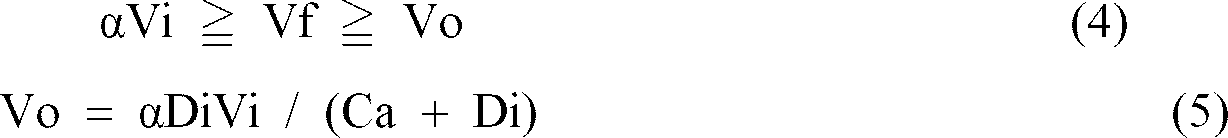
- A method of producing a ring-like casing film as set forth in claim 1, wherein said tubular film is spirally fed so as to satisfy conditions given by the following formulae (6) and (7):

- A method of producing a ring-like casing film as set forth in claim 1, wherein said tubular film is heated and shrunk by carrying out heat-treatment which satisfies a condition given by the following formula:

- A method of producing a ring-like casing film as set forth in claim 1, wherein a pressure of gas charged in said tubular film is adjusted so as to satisfy the following formula (9):

- An apparatus for producing a ring-like casing film, comprising:
a means for continuously introducing a tubular film charged with gas;
an array of a plurality of rod-like rolls which can be rotated about their axes, and which are circumferentially arranged with gaps therebetween; for wounding therearound said introduced tubular film:
a drive means for rotating said rod-like rolls about their axes;
a guide means for spirally feeding said tubular film wound around said array of rod-like rolls;
a main heating means located inside of said array of rod-like rolls, for radially blowing heated gas to an upstream side of said tubular film spirally fed around said array of rod-like rolls through the gaps between said rod-like rolls;
a cooling means for radially blowing cooling air to a downstream side of said tubular film spirally fed around said array of rod-like rolls through the gaps between said rod-like rolls; and
a means for taking up said heat-shrunk tubular film from said array of rod-like rolls. - An apparatus for producing a ring-like casing film as set forth in claim 12, wherein said introducing means is composed of a pair of inlet side pinch rollers, and said taking-up means is composed of a pair of outlet side pinch rollers.
- An apparatus for producing a ring-like casing film as set forth in claim 12, wherein said array of rod-like rolls are surrounded by an auxiliary heating means on the upstream side of said tubular film which is spirally fed around said array rod-like rolls, for blowing heated gas onto the outer peripheries of the turns of said tubular film; and further, an auxiliary cooling means is provided on the downstream side of said tubular film which is spirally fed around said array of rod-like rolls, for blowing cooling air to the outer peripheries of the turns of said tubular film.
- An apparatus for producing a ring-like casing film as set forth in claim 13, wherein said inlet side pinch rollers and said outlet side pinch rollers are spaced from said array of rod-like rolls, radially from the array, and at least either said inlet side pinch rollers or said outlet side pinch rollers are arranged so as to movable to and from said array so as to adjust the pressure of gas charged in said tubular film.
- An apparatus for producing a ring-like casing film as set forth in claim 12, wherein said array of rod-like rolls satisfies conditions given by the following formulae (10), (11) and (12):

- An apparatus for producing a ring-like casing film as set forth in claim 13, wherein said main heat-treatment means is a gas conduit formed therein several air jet holes at its outer periphery.
- An apparatus for producing a ring-like casing film as set forth in claim 14, wherein said auxiliary heating means has a diffusion plate surrounding said array of rod-like rolls on the upstream side of said tubular film spirally fed around said array, heated gas is blown to the outer peripheries of turns of said tubular film through said diffusion plate.
- An apparatus for producing a ring-like casing film as set forth in claim 14, wherein said auxiliary cooling means is composed of a plurality of blowers in combination.
- An apparatus for producing a ring-like casing film as set forth in claim 12, wherein said rod-like rolls are coated over their outer surfaces with ethylene tetrafluoride resin or the like.
- An apparatus for producing a ring-like casing film as set forth in claim 12, wherein said guide means is composed of guide pins arranged at predetermined intervals in the longitudinal direction of said rod-like rolls, and are extended radially of said array of rod-like rolls.
- An apparatus for producing a ring-like casing film as set forth in claim 21, wherein each of said guide pins is a composed of a stationary center shaft and a rotary member rotatably fitted on said stationary center shaft and having a lubricity given by ethylene tetrafluoride resin or the like.
Applications Claiming Priority (4)
| Application Number | Priority Date | Filing Date | Title |
|---|---|---|---|
| JP1355194 | 1994-02-07 | ||
| JP1355194 | 1994-02-07 | ||
| JP13551/94 | 1994-02-07 | ||
| PCT/JP1995/000158 WO1995021052A1 (en) | 1994-02-07 | 1995-02-07 | Method and apparatus for producing ring-like casing film |
Publications (3)
| Publication Number | Publication Date |
|---|---|
| EP0744273A1 true EP0744273A1 (en) | 1996-11-27 |
| EP0744273A4 EP0744273A4 (en) | 1997-12-17 |
| EP0744273B1 EP0744273B1 (en) | 2001-11-14 |
Family
ID=11836310
Family Applications (1)
| Application Number | Title | Priority Date | Filing Date |
|---|---|---|---|
| EP95907846A Expired - Lifetime EP0744273B1 (en) | 1994-02-07 | 1995-02-07 | Method and apparatus for producing ring-shaped casing film |
Country Status (3)
| Country | Link |
|---|---|
| EP (1) | EP0744273B1 (en) |
| DE (1) | DE69523897T2 (en) |
| WO (1) | WO1995021052A1 (en) |
Cited By (7)
| Publication number | Priority date | Publication date | Assignee | Title |
|---|---|---|---|---|
| US5951943A (en) * | 1996-12-07 | 1999-09-14 | Kalle Nalo Gmbh | Process and apparatus for continuously forming rings of thermoplastic, shrinkable tubular casings |
| DE19710402C2 (en) * | 1997-03-13 | 2001-09-20 | Kalle Nalo Gmbh | Method and device for producing hoses or sleeves in a curved shape |
| CN101700049B (en) * | 2009-03-27 | 2011-05-11 | 梧州神冠蛋白肠衣有限公司 | Fiber peeling-off machine |
| EP2364597A1 (en) | 2010-03-10 | 2011-09-14 | CaseTech GmbH | Bent tubular casing with equal casing thickness |
| CN104872262A (en) * | 2015-05-26 | 2015-09-02 | 佛山市高明区德福隆生物科技有限公司 | Double sausage casing dial wheels for casing shrinking machine |
| CN107853369A (en) * | 2017-12-06 | 2018-03-30 | 广东德福隆生物科技有限公司 | One kind spray drying unit |
| EP3639669A1 (en) | 2010-03-10 | 2020-04-22 | Kolotech Fertigungstechniken GmbH | Device and method for producing a ringed tubular casing with equal casing thickness |
Citations (1)
| Publication number | Priority date | Publication date | Assignee | Title |
|---|---|---|---|---|
| EP0500216A2 (en) * | 1991-02-19 | 1992-08-26 | ATCOFLEX, Inc. | Removable core for a shrinkable tubular sheath and method and apparatus for producing same |
Family Cites Families (3)
| Publication number | Priority date | Publication date | Assignee | Title |
|---|---|---|---|---|
| JPS4942542B1 (en) * | 1969-12-29 | 1974-11-15 | ||
| JPS5039112B2 (en) * | 1971-08-10 | 1975-12-15 | ||
| DE2322220B1 (en) * | 1973-05-03 | 1974-10-03 | Wolff Walsrode Ag, 3030 Walsrode | Method and device for the continuous production of thermoplastic, shrinkable tubular casings |
-
1995
- 1995-02-07 EP EP95907846A patent/EP0744273B1/en not_active Expired - Lifetime
- 1995-02-07 DE DE69523897T patent/DE69523897T2/en not_active Expired - Lifetime
- 1995-02-07 WO PCT/JP1995/000158 patent/WO1995021052A1/en active IP Right Grant
Patent Citations (1)
| Publication number | Priority date | Publication date | Assignee | Title |
|---|---|---|---|---|
| EP0500216A2 (en) * | 1991-02-19 | 1992-08-26 | ATCOFLEX, Inc. | Removable core for a shrinkable tubular sheath and method and apparatus for producing same |
Non-Patent Citations (1)
| Title |
|---|
| See also references of WO9521052A1 * |
Cited By (7)
| Publication number | Priority date | Publication date | Assignee | Title |
|---|---|---|---|---|
| US5951943A (en) * | 1996-12-07 | 1999-09-14 | Kalle Nalo Gmbh | Process and apparatus for continuously forming rings of thermoplastic, shrinkable tubular casings |
| DE19710402C2 (en) * | 1997-03-13 | 2001-09-20 | Kalle Nalo Gmbh | Method and device for producing hoses or sleeves in a curved shape |
| CN101700049B (en) * | 2009-03-27 | 2011-05-11 | 梧州神冠蛋白肠衣有限公司 | Fiber peeling-off machine |
| EP2364597A1 (en) | 2010-03-10 | 2011-09-14 | CaseTech GmbH | Bent tubular casing with equal casing thickness |
| EP3639669A1 (en) | 2010-03-10 | 2020-04-22 | Kolotech Fertigungstechniken GmbH | Device and method for producing a ringed tubular casing with equal casing thickness |
| CN104872262A (en) * | 2015-05-26 | 2015-09-02 | 佛山市高明区德福隆生物科技有限公司 | Double sausage casing dial wheels for casing shrinking machine |
| CN107853369A (en) * | 2017-12-06 | 2018-03-30 | 广东德福隆生物科技有限公司 | One kind spray drying unit |
Also Published As
| Publication number | Publication date |
|---|---|
| EP0744273B1 (en) | 2001-11-14 |
| EP0744273A4 (en) | 1997-12-17 |
| DE69523897D1 (en) | 2001-12-20 |
| DE69523897T2 (en) | 2002-08-22 |
| WO1995021052A1 (en) | 1995-08-10 |
Similar Documents
| Publication | Publication Date | Title |
|---|---|---|
| US7550102B2 (en) | Method for producing a helically shaped, seamless multi-walled cylindrical article | |
| KR860000805B1 (en) | Apparatus and method manufacturing corrugated tubes | |
| US5248366A (en) | Method for helical cutting of a flexible tubular sheet of polymeric material | |
| US20110210471A1 (en) | Method and apparatus for manufacture of a polymer film, which is oriented under an angle to its longitudinal direction | |
| JPH0592496A (en) | Method for producing thin wall tube made of fluororesin such as polytetrafluoroethylene | |
| EP0744273A1 (en) | Method and apparatus for producing ring-like casing film | |
| US4118843A (en) | Processes and apparatus for thermal treatment of filaments | |
| JPS62158017A (en) | Device and method of manufacturing thin tube | |
| EP0061931B1 (en) | Method and apparatus for stretching thermoplastic polymer films | |
| JP3796532B2 (en) | Groove forming device for cylindrical surface | |
| JP4008023B2 (en) | Tubular resin film cutting and winding apparatus and cutting and winding method | |
| US5361469A (en) | Apparatus for helical cutting of a flexible tubular sheet of polymeric material | |
| US4650407A (en) | Cooling and guiding device for thermoplastic synthetic resin films | |
| EP0846547B1 (en) | Method and apparatus for continuously curving thermoplastic shrinkable tubular casings | |
| JPS62240108A (en) | Apparatus for continuous production of internally spiral-grooved pipe | |
| US3857917A (en) | Process for the production of tubular films from thermoplastic materials | |
| CA2127810C (en) | Corrugated pipe manufacturing apparatus | |
| US7687010B2 (en) | Process and apparatus for pumping gases in a film | |
| US5330345A (en) | Apparatus and method for continuously winding a length of material into a helical form | |
| SU874382A1 (en) | Unit for producing bidirectionally oriented sleeve-type polymeric films | |
| EP0873847A2 (en) | Plant for the production of plastic tubular films with a biaxial orientation and an in-line stabilisation phase | |
| US20140377397A1 (en) | Apparatus for manufacture of a polymer film, which is oriented under an angle to its longitudinal direction | |
| SU483821A3 (en) | Installation for the manufacture of tubular film of thermoplastic polymers by extrusion | |
| KR100536125B1 (en) | A Vacuum Chamber With Taper Type Expansion Pipe For Heat Shrinkable Tube | |
| JPS5912176Y2 (en) | Heat shrink tube manufacturing equipment |
Legal Events
| Date | Code | Title | Description |
|---|---|---|---|
| PUAI | Public reference made under article 153(3) epc to a published international application that has entered the european phase |
Free format text: ORIGINAL CODE: 0009012 |
|
| AK | Designated contracting states |
Kind code of ref document: A1 Designated state(s): BE DE NL |
|
| 17P | Request for examination filed |
Effective date: 19960830 |
|
| A4 | Supplementary search report drawn up and despatched | ||
| AK | Designated contracting states |
Kind code of ref document: A4 Designated state(s): BE DE NL |
|
| 17Q | First examination report despatched |
Effective date: 20000111 |
|
| GRAG | Despatch of communication of intention to grant |
Free format text: ORIGINAL CODE: EPIDOS AGRA |
|
| RTI1 | Title (correction) |
Free format text: METHOD AND APPARATUS FOR PRODUCING RING-SHAPED CASING FILM |
|
| RAP1 | Party data changed (applicant data changed or rights of an application transferred) |
Owner name: ASAHI KASEI KABUSHIKI KAISHA |
|
| GRAG | Despatch of communication of intention to grant |
Free format text: ORIGINAL CODE: EPIDOS AGRA |
|
| GRAH | Despatch of communication of intention to grant a patent |
Free format text: ORIGINAL CODE: EPIDOS IGRA |
|
| GRAH | Despatch of communication of intention to grant a patent |
Free format text: ORIGINAL CODE: EPIDOS IGRA |
|
| GRAA | (expected) grant |
Free format text: ORIGINAL CODE: 0009210 |
|
| AK | Designated contracting states |
Kind code of ref document: B1 Designated state(s): BE DE NL |
|
| REF | Corresponds to: |
Ref document number: 69523897 Country of ref document: DE Date of ref document: 20011220 |
|
| PLBE | No opposition filed within time limit |
Free format text: ORIGINAL CODE: 0009261 |
|
| STAA | Information on the status of an ep patent application or granted ep patent |
Free format text: STATUS: NO OPPOSITION FILED WITHIN TIME LIMIT |
|
| 26N | No opposition filed | ||
| PGFP | Annual fee paid to national office [announced via postgrant information from national office to epo] |
Ref country code: DE Payment date: 20100219 Year of fee payment: 16 Ref country code: BE Payment date: 20100125 Year of fee payment: 16 |
|
| PGFP | Annual fee paid to national office [announced via postgrant information from national office to epo] |
Ref country code: NL Payment date: 20100218 Year of fee payment: 16 |
|
| BERE | Be: lapsed |
Owner name: *ASAHI KASEI K.K. Effective date: 20110228 |
|
| REG | Reference to a national code |
Ref country code: NL Ref legal event code: V1 Effective date: 20110901 |
|
| PG25 | Lapsed in a contracting state [announced via postgrant information from national office to epo] |
Ref country code: BE Free format text: LAPSE BECAUSE OF NON-PAYMENT OF DUE FEES Effective date: 20110228 |
|
| PG25 | Lapsed in a contracting state [announced via postgrant information from national office to epo] |
Ref country code: NL Free format text: LAPSE BECAUSE OF NON-PAYMENT OF DUE FEES Effective date: 20110901 |
|
| REG | Reference to a national code |
Ref country code: DE Ref legal event code: R119 Ref document number: 69523897 Country of ref document: DE Effective date: 20110901 |
|
| PG25 | Lapsed in a contracting state [announced via postgrant information from national office to epo] |
Ref country code: DE Free format text: LAPSE BECAUSE OF NON-PAYMENT OF DUE FEES Effective date: 20110901 |