EP0743871B1 - Method for the manufacture of filter wells - Google Patents
Method for the manufacture of filter wells Download PDFInfo
- Publication number
- EP0743871B1 EP0743871B1 EP95909190A EP95909190A EP0743871B1 EP 0743871 B1 EP0743871 B1 EP 0743871B1 EP 95909190 A EP95909190 A EP 95909190A EP 95909190 A EP95909190 A EP 95909190A EP 0743871 B1 EP0743871 B1 EP 0743871B1
- Authority
- EP
- European Patent Office
- Prior art keywords
- filter
- bottom portion
- well
- tool
- wall
- Prior art date
- Legal status (The legal status is an assumption and is not a legal conclusion. Google has not performed a legal analysis and makes no representation as to the accuracy of the status listed.)
- Expired - Lifetime
Links
- 238000000034 method Methods 0.000 title claims description 24
- 238000004519 manufacturing process Methods 0.000 title description 8
- 239000000463 material Substances 0.000 claims abstract description 6
- 239000004033 plastic Substances 0.000 claims abstract description 4
- 238000001746 injection moulding Methods 0.000 claims description 23
- 238000001914 filtration Methods 0.000 claims description 7
- 238000004080 punching Methods 0.000 claims description 2
- 239000007788 liquid Substances 0.000 abstract description 9
- 238000002347 injection Methods 0.000 description 9
- 239000007924 injection Substances 0.000 description 9
- 238000007789 sealing Methods 0.000 description 9
- 239000012528 membrane Substances 0.000 description 5
- 239000007790 solid phase Substances 0.000 description 4
- 239000004743 Polypropylene Substances 0.000 description 3
- 239000007791 liquid phase Substances 0.000 description 3
- 239000000155 melt Substances 0.000 description 3
- 230000002093 peripheral effect Effects 0.000 description 3
- -1 polypropylene Polymers 0.000 description 3
- 229920001155 polypropylene Polymers 0.000 description 3
- 229920005992 thermoplastic resin Polymers 0.000 description 3
- 238000005192 partition Methods 0.000 description 2
- 238000007711 solidification Methods 0.000 description 2
- 230000008023 solidification Effects 0.000 description 2
- 239000000243 solution Substances 0.000 description 2
- 238000002604 ultrasonography Methods 0.000 description 2
- 241000894006 Bacteria Species 0.000 description 1
- 230000006820 DNA synthesis Effects 0.000 description 1
- 239000004952 Polyamide Substances 0.000 description 1
- 238000004026 adhesive bonding Methods 0.000 description 1
- 238000005842 biochemical reaction Methods 0.000 description 1
- 238000005266 casting Methods 0.000 description 1
- 238000005119 centrifugation Methods 0.000 description 1
- 238000010276 construction Methods 0.000 description 1
- 238000005530 etching Methods 0.000 description 1
- 230000004927 fusion Effects 0.000 description 1
- 239000003365 glass fiber Substances 0.000 description 1
- 238000001802 infusion Methods 0.000 description 1
- 238000000465 moulding Methods 0.000 description 1
- 150000007523 nucleic acids Chemical class 0.000 description 1
- 102000039446 nucleic acids Human genes 0.000 description 1
- 108020004707 nucleic acids Proteins 0.000 description 1
- 229920002647 polyamide Polymers 0.000 description 1
- 239000011148 porous material Substances 0.000 description 1
- 238000002360 preparation method Methods 0.000 description 1
- 238000003825 pressing Methods 0.000 description 1
- 238000011084 recovery Methods 0.000 description 1
- 239000000126 substance Substances 0.000 description 1
- 241001515965 unidentified phage Species 0.000 description 1
- 238000003466 welding Methods 0.000 description 1
Images

Classifications
-
- B—PERFORMING OPERATIONS; TRANSPORTING
- B29—WORKING OF PLASTICS; WORKING OF SUBSTANCES IN A PLASTIC STATE IN GENERAL
- B29C—SHAPING OR JOINING OF PLASTICS; SHAPING OF MATERIAL IN A PLASTIC STATE, NOT OTHERWISE PROVIDED FOR; AFTER-TREATMENT OF THE SHAPED PRODUCTS, e.g. REPAIRING
- B29C45/00—Injection moulding, i.e. forcing the required volume of moulding material through a nozzle into a closed mould; Apparatus therefor
- B29C45/16—Making multilayered or multicoloured articles
- B29C45/1671—Making multilayered or multicoloured articles with an insert
-
- B—PERFORMING OPERATIONS; TRANSPORTING
- B01—PHYSICAL OR CHEMICAL PROCESSES OR APPARATUS IN GENERAL
- B01D—SEPARATION
- B01D29/00—Filters with filtering elements stationary during filtration, e.g. pressure or suction filters, not covered by groups B01D24/00 - B01D27/00; Filtering elements therefor
- B01D29/01—Filters with filtering elements stationary during filtration, e.g. pressure or suction filters, not covered by groups B01D24/00 - B01D27/00; Filtering elements therefor with flat filtering elements
- B01D29/012—Making filtering elements
-
- B—PERFORMING OPERATIONS; TRANSPORTING
- B01—PHYSICAL OR CHEMICAL PROCESSES OR APPARATUS IN GENERAL
- B01D—SEPARATION
- B01D29/00—Filters with filtering elements stationary during filtration, e.g. pressure or suction filters, not covered by groups B01D24/00 - B01D27/00; Filtering elements therefor
- B01D29/01—Filters with filtering elements stationary during filtration, e.g. pressure or suction filters, not covered by groups B01D24/00 - B01D27/00; Filtering elements therefor with flat filtering elements
- B01D29/05—Filters with filtering elements stationary during filtration, e.g. pressure or suction filters, not covered by groups B01D24/00 - B01D27/00; Filtering elements therefor with flat filtering elements supported
-
- B—PERFORMING OPERATIONS; TRANSPORTING
- B01—PHYSICAL OR CHEMICAL PROCESSES OR APPARATUS IN GENERAL
- B01D—SEPARATION
- B01D29/00—Filters with filtering elements stationary during filtration, e.g. pressure or suction filters, not covered by groups B01D24/00 - B01D27/00; Filtering elements therefor
- B01D29/085—Funnel filters; Holders therefor
-
- B—PERFORMING OPERATIONS; TRANSPORTING
- B29—WORKING OF PLASTICS; WORKING OF SUBSTANCES IN A PLASTIC STATE IN GENERAL
- B29L—INDEXING SCHEME ASSOCIATED WITH SUBCLASS B29C, RELATING TO PARTICULAR ARTICLES
- B29L2031/00—Other particular articles
- B29L2031/14—Filters
-
- Y—GENERAL TAGGING OF NEW TECHNOLOGICAL DEVELOPMENTS; GENERAL TAGGING OF CROSS-SECTIONAL TECHNOLOGIES SPANNING OVER SEVERAL SECTIONS OF THE IPC; TECHNICAL SUBJECTS COVERED BY FORMER USPC CROSS-REFERENCE ART COLLECTIONS [XRACs] AND DIGESTS
- Y10—TECHNICAL SUBJECTS COVERED BY FORMER USPC
- Y10S—TECHNICAL SUBJECTS COVERED BY FORMER USPC CROSS-REFERENCE ART COLLECTIONS [XRACs] AND DIGESTS
- Y10S264/00—Plastic and nonmetallic article shaping or treating: processes
- Y10S264/48—Processes of making filters
Definitions
- the present invention relates to the production of filter wells useful for separating a solid phase from a liquid.
- Separating a solid phase from a solution is a common process in a biotechnological laboratory and is carried out mainly either by centrifugation or by collecting the solid phase on a filter.
- a filter As examples, the preparation of nucleic acids from bacteria, bacteriophages, DNA-synthesis, PCR products, etc., can be mentioned.
- filter wells i.e. a small tube or the like containing a filter through which the liquid phase is forced by applying vacuum on the underside of the filter or pressure on the upside of the filter.
- the use of a positive pressure on the upside of the filter has i.a. the advantages that the solid phase as well as the liquid phase easily can be collected and that a greater pressure difference between the upside and the underside of the filter is possible (greater than 1 bar) but requires on the other hand a very good sealing between the filter and the wall of the filter well in order to avoid a leakage of liquid past the filter.
- a method of providing the necessary sealing upon filtering by means of vacuum is described in WO 86/07606, where a test plate of microtitre well type is produced in that a filter membrane is placed between an upper part and lower part which are then pressed together so that a number of wells provided with filters, are formed.
- the sealing between the wells is secured in that the upper and lower parts between the well portions are provided with matching ridges and recesses so that the filter membrane breaks upon pressing the parts together when a ridge is forced into the corresponding recess.
- the upper and lower parts are then fused together in these portions by means of heat, e.g. by use of ultrasound or thermal bonding.
- this method is limited to a microtitre well format with fixed wells.
- EP-A-328 038 describes the production of a filter well by injection moulding of the filter well in one piece and at the same time casting the filter edge integral with the wall of the well.
- This method has for example the disadvantage that it does not allow the forming of any support surface for the filter.
- the filter is compressed during the forming process which can cause damage to the active filtering surface of the filter.
- only one side of the filter is fixed in the wall of the filter well.
- US-A-4,113,627 describes the production of a filter for infusion liquids where two preformed filter housing halves with a filter clamped therebetween, are sealed at the outer edge by injection moulding of a thermoplastic resin. Besides the fact that the manufacturing process is relatively complicated, the clamping of the filter between the housing parts can damage the filter surface. Moreover, only one side of the filter is cast integral with the thermoplastic resin.
- the present invention relates to a method of producing separate filter wells, which does not exhibit the disadvantages and inconveniences mentioned above at the same time as it in combination with a simple procedure secures an extraordinary sealing of the edge of the filter or the membrane so that there is no risk of any leakage past the filter when a positive pressure is applied to the upside of the filter. Moreover, the filter well gives support to the filter at high pressures.
- the invention is based upon the idea of producing the filter well by forming of plastic and at the same time fix the filter in the filter well.
- the filter is fixed in that the filter edge is double-sidedly embedded or fused into the wall of the well during the actual forming process at the same time as the filter is supported by a bottom portion formed in advance and having a supporting surface for the filter.
- the filter well is produced by first forming by injection moulding a bottom portion provided with a supporting surface for the filter and a preferably central outlet opening for freely dripping liquid. Thereafter, a filter (or membrane) is applied on the supporting surface of the bottom portion so that the filter at least essentially covers the whole bottom portion. Finally, the cylindrical wall portion of the filter well is formed by injection moulding against the bottom portion with the lower part of the wall portion surrounding the edge of the filter and the upper edge of the bottom portion so that the bottom and wall portions form a fused unit, the outer edge of the filter being fused into the filter well material.
- the supporting surface extends inside the inner side of the cylinder wall so that it supports at least part of the active filtering surface of the filter.
- the filter is somewhat larger than the bottom portion so that the filter, before the forming of the cylindrical wall portion, extends beyond the periphery of the bottom portion.
- the bottom portion is produced with a fine flow channel pattern in the supporting surface, which results in very small losses upon recovery of the liquid phase.
- a device for producing the filter well thus, has means for forming the bottom portion, means for applying a filter on the bottom portion, and means for forming the wall portion of the filter well against the bottom portion.
- Such a device can advantageously be in the form of a single moulding tool with several stations.
- the wall portion and the bottom portion of the filter well are produced from the same material, particularly a thermoplastic resin.
- the tool parts illustrated in Figs. 1-7 are included in an integrated tool for carrying out all steps in the production of the filter well.
- the tool which for reasons of clarity is not shown in its whole, has a stationary part shown uppermost in the Figures and, therefore, henceforth called upper part, and a movable, lower part in the Figures, henceforth called lower part which by rotation in the horizontal direction can be moved to different stations of the upper part.
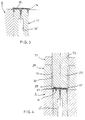
- Fig. 1 shows the tool portion for injection moulding of the bottom portion of the filter well.
- the portion that is included in the above-mentioned upper, stationary tool part is denoted 1 and the portion that is included in the movable lower part is denoted 2.
- the two parts 1 and 2 are horizontally displaceable relative to each other, e.g. by rotation, in a partition plane 3 when the lower part 2 of the tool has been moved away from the upper part 1. (The same reference numerals for the upper and lower tool part, respectively, are used throughout the other Figures.)
- the upper tool part 1 has a cylindrical, upper mould element 4 having a central, threaded boring 5 which abrubtly changes into a boring 6 with a smaller diameter. The latter extends in its turn up to the lower end 7 of the mould element.
- a pin 8 adapted to the borings 5, 6 is screwed into the boring 5 and has a needle portion 9 which extends below the mould element end 7.
- a pattern of elongated ridges 10 which run radially and, possibly, also in the transverse direction, e.g. annularly, starting a distance inside the edge and up to the bore 6, are formed in the end 7 for forming flow channels in the bottom of the filter well.
- a matching, cylindrical, lower mould element 11 is vertically displaceable in the lower tool part 2 right in front of the mould element 4. Together with the end 7 of the mould element 4 and the uppermost part of the adjacent main portion of the lower tool part 2, the upper part 12 of this mould element 11 is designed to delimit a mould cavity 13 for forming the bottom portion of the filter well.
- the mould cavity 13 is shown filled with the desired injection moulding material, e.g. polypropylene, injected via an opening which is not shown in this connection for reasons of clarity.
- the finished bottom portion 16 has a drop tip 17 which encloses a central opening 18, and a peripheral collar portion 19.
- the upside has a system of flow channels 20 formed by the above-mentioned ridges 10 in the end 7 of the mould element 4, and which extend radially from an unpatterned rim portion 21 to the opening 18.
- there may be connections between the radial channels e.g. in the form of annular channels which are concentric with the opening 18 in the bottom portion 16.
- the lower mould element 11 is swung right in front of a vertical punch 22 which runs in a hole 23 in the tool part 1.
- a central boring 24 in the punch 22 can be connected to a source of compressed air/vacuum and ends in e.g. a cross- or star-shaped end recess 25.
- the punch 22 is adapted to punch out a filter disc from a filter sheet or strip 26, e.g. a so called sterile filter or a membrane of polyamide with fine pores, a polypropylene filter or a glass fibre filter, which is fed over the punch hole 23 via a horizontal gap 27 in the upper tool part.
- a filter sheet or strip 26 e.g. a so called sterile filter or a membrane of polyamide with fine pores, a polypropylene filter or a glass fibre filter
- the punch 22 has punched out a filter disc 28 which is kept against the punch via vacuum connected to the boring 24 in the center of the punch.
- the vacuum is changed into positive pressure so that the filter is pressed against the bottom portion 16 and the filter is thereafter kept against the bottom portion via the vacuum connected earlier to the boring 15, which in this station reaches the filter through the central opening 18 in the bottom portion.
- the punch 22 is lifted up and the lower tool part 2 is swung to a further station of the upper tool part 1 for injection moulding of the cylindrical wall portion of the filter well.
- Fig. 3 the portion in question of the lower tool part is shown on its way to this injection moulding station.
- the vacuum in the boring 15 is still applied so that the filter 28 all the time is kept against the bottom portion 16 of the filter well.
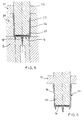
- Fig. 4 shows the lower tool part with the bottom portion 16 injection moulded earlier still in place at the next injection moulding station.
- the upper tool part has here two portions arranged on top of each other and being movable relative to each other, of which the lower tool portion 29 delimits a cavity 30 which can be opened and which is arranged right before the injection moulded bottom portion 16, while the upper tool portion 31 has a boring 32 aligned with the cavity 30, which slidably receives a vertical, cylindrical element 33. The latter extends with its lower part into the cavity 30 to form a mould core.
- this mould core delimits a mould cavity 34 for injection moulding of the cylindrical wall portion of the filter well.
- the bottom portion 16 is somewhat elevated above the lower tool part 2 for the mould cavity to extend beyond and surround the upper edge of the bottom portion 16.
- An effective sealing between the cylindrical core 33 and the injection moulded bottom portion 16 is secured in that the filter 28 is clamped against the unpatterned (i.e. without any flow channels) rim portion 21 of the bottom portion 16 via a corresponding, vertically extending rim portion 35 at the end of the cylindrical core 33.
- the outermost portion of the filter 28 and the underlying portion of the already injection moulded bottom portion 16 are, however, not covered by the cylindrical core 33 but, as apparent from the Figure, extend into the mould cavity 34.
- a plastic melt e.g. polypropylene
- the melt surrounds the upper edge of the bottom portion 16 and extends a distance over the filter 28 so that this is embedded or moulded into the cylindrical wall.
- the injection moulded cylindrical portion 36 tends to contract relative to the bottom portion 16 injection moulded earlier, which leads to that it compresses the embedded filter edge resulting in an extraordinary sealing against the filter.
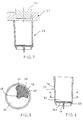
- the filter well 37 is then pushed off the cylindrical core 33 by a downwards directed movement of the tool portion 31 as illustrated in Fig. 7.
- the finished well 37 is shown removed from the injection moulding tool with the filter melted into the same.
- the filter well 37 comprises the bottom and cylindrical portions 16, 36 melted together into one piece with the filter 28 supported on the well bottom which is provided with flow channels 20 and which forms a supporting surface 16a for the filter, wherein a peripheral portion of both sides of the filter is properly melted or fused into the cylindrical portion.
- This fusion of the filter ensures a very effective and safe sealing and consequently there is no risk of any leakage of liquid past the filter when liquid is pressed through the bottom opening 18 via the filter 28.
- a number of flow-equalizing cross-channels 38 are also provided, which extend concentrically with the opening 18.
- the channels 20, 38 as well as the intermediate ridge portions (i.e. the filter supporting portions) 39 preferably have a very small width, e.g. of the order of 0.1 mm. As already mentioned, this leads to that the remaining liquid volume in the filter tube after the filtering will be very small and that the contact surfaces with the filter are minimized so that essentially all of the filter surface is active upon filtration.
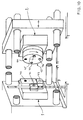
- Fig. 10 illustrates schematically how the earlier mentioned integrated injection moulding tool with the tool stations shown in Figs. 1-7 can be arranged in an injection moulding machine. It should be noted that while in Figs. 1-7 the respective tool portions are shown with the stationary tool part 1 at the top and the movable tool part 2 below, these two tool parts are arranged horizontally as in Fig. 10. Thus, the stationary tool part 1 is located to the left in the Figure, while the movable tool part 2 is located to the right.
- the stationary tool part 1 has a first station 40, corresponding to the tool portion illustrated in Fig. 1, for injection moulding of the bottom portion of the filter well, a second station 41, corresponding to the tool portion in Fig. 2, for punching and applying the filter onto the bottom portion, and a third station 42, corresponding to the tool portion in Figs. 4-7, for injection moulding of the cylindrical portion of the filter well.
- the movable tool part which is laterally displaceable, has a rotatable element 43 with four identical tool portions 44-47 at the same peripheral distance from each other as the distance between the stations 40-42 in the stationary tool part. Three of the portions 44-47 are at each processing instance in active engagement with the stations 40-42 in the stationary tool half 1.
- each station 40, 41 and 42 is provided with several sets, e.g. four sets, of the tool parts included in each station and in that each tool portion 44-47 is provided with as many, e.g. four, sets of these tool parts right before the respective station 40, 41 and 42.
Landscapes
- Chemical & Material Sciences (AREA)
- Chemical Kinetics & Catalysis (AREA)
- Engineering & Computer Science (AREA)
- Manufacturing & Machinery (AREA)
- Mechanical Engineering (AREA)
- Moulds For Moulding Plastics Or The Like (AREA)
- Injection Moulding Of Plastics Or The Like (AREA)
- Filtration Of Liquid (AREA)
- Separation Using Semi-Permeable Membranes (AREA)
Abstract
Description
Claims (8)
- A method of producing a filter well of plastic having a bottom portion (16) with an outlet and supporting a filter (28) provided on top of the outlet, comprising the steps of(i) forming by injection moulding a bottom portion (16) having a supporting surface (16a) for the filter (28) and an outlet opening (18),(ii) applying a filter (28) on the bottom portion (16) so that the filter essentially covers the whole bottom portion, characterised in that the method comprises the further step of(iii) forming by injection moulding the cylindrical wall portion (36) of the filter well against the bottom portion (16) with the lower part of the wall portion surrounding the edge of the filter and the upper edge of the bottom portion so that the bottom and wall portions (16, 36) form a fused unit, the outer edge of the filter (28) being fused into the filter wall material.
- The method according to claim 1, characterized in that the bottom portion (16) and the wall portion (36) are formed from the same material.
- The method according to any one of claims 1-2, characterized in that, during forming of the wall portion (36), the filter (28) inside the edge portion that is to be fused is pressed against a rim portion (21) of the upside of the bottom portion (16).
- The method according to any one of claims 1-3, characterized in that the upside of the bottom portion (16) is formed with radial flow channels (20) which run towards the outlet opening (18), and, possibly, also flow channels (38) which are concentric with the outlet opening and which mutually connects the radial flow channels (20), ridge portions between the flow channels supporting the filter (28).
- The method according to any one of claims 1-4, characterized in that step (ii) comprises punching the filter (28) from a filter blank (26).
- The method according to any one of claims 1-5, characterized in that the filter (28) in step (ii) extends beyond the periphery of the bottom portion (16).
- The method according to any of claims 1-6, characterized in that the supporting surface (16a) of the bottom portion (16) for the filter (28) extends inside the inner side of the cylindrical wall (36) to support at least part of the active filtering surface of the filter (28).
- The method according to any of claims 1-7, characterized in that the outlet opening (18) is centrally located in the bottom portion (16).
Applications Claiming Priority (3)
| Application Number | Priority Date | Filing Date | Title |
|---|---|---|---|
| SE9400436 | 1994-02-10 | ||
| SE9400436A SE9400436D0 (en) | 1994-02-10 | 1994-02-10 | Ways to make filter wells |
| PCT/SE1995/000140 WO1995021677A1 (en) | 1994-02-10 | 1995-02-10 | Method for the manufacture of filter wells |
Publications (2)
| Publication Number | Publication Date |
|---|---|
| EP0743871A1 EP0743871A1 (en) | 1996-11-27 |
| EP0743871B1 true EP0743871B1 (en) | 1998-01-14 |
Family
ID=20392872
Family Applications (1)
| Application Number | Title | Priority Date | Filing Date |
|---|---|---|---|
| EP95909190A Expired - Lifetime EP0743871B1 (en) | 1994-02-10 | 1995-02-10 | Method for the manufacture of filter wells |
Country Status (6)
| Country | Link |
|---|---|
| US (1) | US5885499A (en) |
| EP (1) | EP0743871B1 (en) |
| JP (1) | JP3822902B2 (en) |
| DE (1) | DE69501462T2 (en) |
| SE (1) | SE9400436D0 (en) |
| WO (1) | WO1995021677A1 (en) |
Families Citing this family (31)
| Publication number | Priority date | Publication date | Assignee | Title |
|---|---|---|---|---|
| DE19712484C2 (en) * | 1997-03-25 | 1999-07-08 | Greiner Gmbh | Microplate with transparent bottom and process for its production |
| US6391241B1 (en) * | 1997-06-06 | 2002-05-21 | Corning Incorporated | Method of manufacture for a multiwell plate and/or filter plate |
| JP3390131B2 (en) * | 1997-11-14 | 2003-03-24 | ジー・ピー・ダイキョー株式会社 | Method and apparatus for producing synthetic resin hollow body incorporating intermediate and hollow body made of synthetic resin |
| EP0988881A1 (en) * | 1998-09-25 | 2000-03-29 | EMM International B.V. | Sieving device for paint or the like and method for producing such |
| US6210619B1 (en) * | 1998-10-19 | 2001-04-03 | Ford Motor Company | Method for manufacturing a two-piece plastic assembly |
| US6497567B1 (en) * | 1999-10-04 | 2002-12-24 | Serigraph Inc. | Multi-purpose processing apparatus |
| EP1110611A1 (en) * | 1999-12-23 | 2001-06-27 | 3M Innovative Properties Company | Micro-titer plate and method of making same |
| DE60006234T2 (en) * | 2000-08-30 | 2004-04-22 | Gvs S.P.A., Zola Predosa | Method for producing a container with a pressure compensation device and a container produced in this way |
| US20030183958A1 (en) * | 2002-03-28 | 2003-10-02 | Becton, Dickinson And Company | Multi-well plate fabrication |
| US6716350B2 (en) | 2002-05-03 | 2004-04-06 | Millipore Corporation | Microplate protective tray undercover |
| US7211224B2 (en) * | 2002-05-23 | 2007-05-01 | Millipore Corporation | One piece filtration plate |
| WO2005037413A1 (en) * | 2003-10-17 | 2005-04-28 | Fuji Photo Film Co., Ltd. | Porous film cartridge |
| US20070148649A1 (en) * | 2003-10-21 | 2007-06-28 | Fuji Photo Film Co., Ltd. | Cartridge for nucleic acid separation and purification and method for producing the same |
| JP4511914B2 (en) * | 2003-12-12 | 2010-07-28 | ベクトン・ディキンソン・アンド・カンパニー | Membrane mounting method |
| US7141198B2 (en) * | 2004-06-17 | 2006-11-28 | Millipore Corporation | Method for the manufacture of a composite filter plate |
| JP4551174B2 (en) * | 2004-09-30 | 2010-09-22 | 富士フイルム株式会社 | Porous membrane cartridge and manufacturing method thereof |
| US8631953B2 (en) * | 2005-08-10 | 2014-01-21 | Abbott Laboratories | Closure for container for holding biological samples |
| US8012349B2 (en) | 2006-11-20 | 2011-09-06 | Orbital Biosciences, Llc | Small volume unitary molded filters and supports for adsorbent beds |
| RU2383382C2 (en) * | 2008-05-29 | 2010-03-10 | Общество с ограниченной ответственностью ООО "Аквафор" (ООО "Аквафор") | Filter cart |
| JP5767481B2 (en) * | 2010-02-15 | 2015-08-19 | 丸善石油化学株式会社 | Functional container molding method, molding die, and functional container manufactured using these |
| SE535159C2 (en) * | 2010-09-02 | 2012-05-02 | Veolia Water Solutions & Tech | Method of manufacturing a filter segment into a disk filter as well as the filter segment |
| US10456786B2 (en) | 2013-03-12 | 2019-10-29 | Abbott Laboratories | Septums and related methods |
| US20150108682A1 (en) * | 2013-10-23 | 2015-04-23 | Lincoln Global, Inc. | Method of making a filter seal |
| TWI512292B (en) * | 2014-09-04 | 2015-12-11 | Taiwan Green Point Entpr Co | Method for making thin film biochip |
| USD820456S1 (en) | 2015-06-09 | 2018-06-12 | Lincoln Global, Inc. | Belt bracket of powered air purifying respirator |
| USD857306S1 (en) | 2018-03-07 | 2019-08-20 | Lincoln Global, Inc. | Top of helmet shell |
| USD848077S1 (en) | 2018-03-07 | 2019-05-07 | Lincoln Global, Inc. | Cover lens frame |
| USD860546S1 (en) | 2018-03-07 | 2019-09-17 | Lincoln Global, Inc. | Top shell for helmet |
| USD853044S1 (en) | 2018-03-07 | 2019-07-02 | Lincoln Global, Inc. | Inner shell of a helmet |
| USD851841S1 (en) | 2018-03-23 | 2019-06-18 | Lincoln Global, Inc. | Shield holder frame |
| IT202200025881A1 (en) * | 2022-12-16 | 2024-06-16 | Ergotech Srl | PROCEDURE FOR THE MANUFACTURE BY CO-MOULDING BY INJECTION OF PLASTIC MATERIAL OF A COMPONENT INTEGRATING A HYDROPHOBIC POLYMERIC MEMBRANE AND CORRESPONDING PRODUCTION ISLAND |
Family Cites Families (9)
| Publication number | Priority date | Publication date | Assignee | Title |
|---|---|---|---|---|
| DE2018323A1 (en) * | 1969-04-16 | 1971-02-04 | Beckman Instruments Ine , Fuller ton, Calif (VStA) | Plastic filter cup with filter paper bottom - for automatic chemical analysis apparatus |
| US4113627A (en) * | 1976-01-28 | 1978-09-12 | Filtertek, Inc. | Process for making hermetically sealed filter units and filters made thereby |
| AU1031883A (en) * | 1982-02-08 | 1983-08-18 | Abbott Laboratories | Injection moulding microbial filters |
| US4948442A (en) * | 1985-06-18 | 1990-08-14 | Polyfiltronics, Inc. | Method of making a multiwell test plate |
| DE3804344C1 (en) * | 1988-02-12 | 1989-05-11 | Sartorius Gmbh, 3400 Goettingen, De | |
| SE9002579D0 (en) * | 1990-08-07 | 1990-08-07 | Pharmacia Ab | METHOD AND APPARATUS FOR CARRYING OUT BIOCHEMICAL REACTIONS |
| US5269917A (en) * | 1992-02-28 | 1993-12-14 | Millipore Corporation | Filtration apparatus having stress relief groove |
| US5443723A (en) * | 1994-02-22 | 1995-08-22 | Millipore Corporation | Membrane support and sealing apparatus |
| US5556541A (en) * | 1994-04-26 | 1996-09-17 | Filtertek, Inc. | Process for making hermetically sealed filter units and filters made thereby |
-
1994
- 1994-02-10 SE SE9400436A patent/SE9400436D0/en unknown
-
1995
- 1995-02-10 JP JP52116695A patent/JP3822902B2/en not_active Expired - Lifetime
- 1995-02-10 DE DE69501462T patent/DE69501462T2/en not_active Expired - Lifetime
- 1995-02-10 EP EP95909190A patent/EP0743871B1/en not_active Expired - Lifetime
- 1995-02-10 WO PCT/SE1995/000140 patent/WO1995021677A1/en not_active Ceased
- 1995-02-10 US US08/687,488 patent/US5885499A/en not_active Expired - Lifetime
Also Published As
| Publication number | Publication date |
|---|---|
| SE9400436D0 (en) | 1994-02-10 |
| JPH09509092A (en) | 1997-09-16 |
| EP0743871A1 (en) | 1996-11-27 |
| DE69501462D1 (en) | 1998-02-19 |
| DE69501462T2 (en) | 1999-02-18 |
| JP3822902B2 (en) | 2006-09-20 |
| US5885499A (en) | 1999-03-23 |
| WO1995021677A1 (en) | 1995-08-17 |
Similar Documents
| Publication | Publication Date | Title |
|---|---|---|
| US5885499A (en) | Method for the manufacture of filter wells | |
| EP0989912B1 (en) | Filter plate | |
| US8012349B2 (en) | Small volume unitary molded filters and supports for adsorbent beds | |
| EP0181366B1 (en) | Improvements in and relating to filters | |
| US6692596B2 (en) | Micro-titer plate and method of making same | |
| US7311880B2 (en) | Well-less filtration device | |
| EP0396385B1 (en) | A friction welding process and a filter formed thereby | |
| US6403008B1 (en) | Method for overwelding filter cassettes and devices produced therefrom | |
| US5273560A (en) | Filter element and method for producing the same | |
| WO2001051206A1 (en) | Micro-titer plate with filter inserts and related fabrication method | |
| EP0340914B1 (en) | Filter | |
| EP1239960B1 (en) | Micro-titer plate and method of making same | |
| JP2002519169A (en) | Filter element and manufacturing method thereof | |
| US7297269B2 (en) | Cross-flow filtration cassettes and methods for fabrication of same | |
| US20050103703A1 (en) | Method of assembling a filtration plate | |
| GB2068821A (en) | Improvements in or relating to a receptacle | |
| JPH01148522A (en) | Method and apparatus for manufacturing filter-insert molded product | |
| EP0709132A1 (en) | Fluid filtration device | |
| EP0211155A2 (en) | Disposable filter unit | |
| JP4503276B2 (en) | Filtration device having housing-integrated pleat filter | |
| KR20160067109A (en) | Method for producing a mini-vial with a reduced number of components and the mini-vial thus obtained | |
| RU1837936C (en) | Filter member and method and apparatus for its manufacture | |
| WO2003008100A1 (en) | Device for simultaneous processing of discrete quantities of flowable material |
Legal Events
| Date | Code | Title | Description |
|---|---|---|---|
| PUAI | Public reference made under article 153(3) epc to a published international application that has entered the european phase |
Free format text: ORIGINAL CODE: 0009012 |
|
| 17P | Request for examination filed |
Effective date: 19960729 |
|
| AK | Designated contracting states |
Kind code of ref document: A1 Designated state(s): CH DE FR GB IT LI NL SE |
|
| GRAG | Despatch of communication of intention to grant |
Free format text: ORIGINAL CODE: EPIDOS AGRA |
|
| 17Q | First examination report despatched |
Effective date: 19970303 |
|
| GRAG | Despatch of communication of intention to grant |
Free format text: ORIGINAL CODE: EPIDOS AGRA |
|
| GRAH | Despatch of communication of intention to grant a patent |
Free format text: ORIGINAL CODE: EPIDOS IGRA |
|
| GRAH | Despatch of communication of intention to grant a patent |
Free format text: ORIGINAL CODE: EPIDOS IGRA |
|
| GRAA | (expected) grant |
Free format text: ORIGINAL CODE: 0009210 |
|
| AK | Designated contracting states |
Kind code of ref document: B1 Designated state(s): CH DE FR GB IT LI NL SE |
|
| PG25 | Lapsed in a contracting state [announced via postgrant information from national office to epo] |
Ref country code: NL Free format text: LAPSE BECAUSE OF FAILURE TO SUBMIT A TRANSLATION OF THE DESCRIPTION OR TO PAY THE FEE WITHIN THE PRESCRIBED TIME-LIMIT Effective date: 19980114 Ref country code: LI Free format text: LAPSE BECAUSE OF FAILURE TO SUBMIT A TRANSLATION OF THE DESCRIPTION OR TO PAY THE FEE WITHIN THE PRESCRIBED TIME-LIMIT Effective date: 19980114 Ref country code: IT Free format text: LAPSE BECAUSE OF FAILURE TO SUBMIT A TRANSLATION OF THE DESCRIPTION OR TO PAY THE FEE WITHIN THE PRE;WARNING: LAPSES OF ITALIAN PATENTS WITH EFFECTIVE DATE BEFORE 2007 MAY HAVE OCCURRED AT ANY TIME BEFORE 2007. THE CORRECT EFFECTIVE DATE MAY BE DIFFERENT FROM THE ONE RECORDED.SCRIBED TIME-LIMIT Effective date: 19980114 Ref country code: CH Free format text: LAPSE BECAUSE OF FAILURE TO SUBMIT A TRANSLATION OF THE DESCRIPTION OR TO PAY THE FEE WITHIN THE PRESCRIBED TIME-LIMIT Effective date: 19980114 |
|
| REG | Reference to a national code |
Ref country code: CH Ref legal event code: EP |
|
| REF | Corresponds to: |
Ref document number: 69501462 Country of ref document: DE Date of ref document: 19980219 |
|
| ET | Fr: translation filed | ||
| NLV1 | Nl: lapsed or annulled due to failure to fulfill the requirements of art. 29p and 29m of the patents act | ||
| REG | Reference to a national code |
Ref country code: CH Ref legal event code: PL |
|
| PLBE | No opposition filed within time limit |
Free format text: ORIGINAL CODE: 0009261 |
|
| STAA | Information on the status of an ep patent application or granted ep patent |
Free format text: STATUS: NO OPPOSITION FILED WITHIN TIME LIMIT |
|
| 26N | No opposition filed | ||
| REG | Reference to a national code |
Ref country code: GB Ref legal event code: IF02 |
|
| PGFP | Annual fee paid to national office [announced via postgrant information from national office to epo] |
Ref country code: SE Payment date: 20030205 Year of fee payment: 9 |
|
| PG25 | Lapsed in a contracting state [announced via postgrant information from national office to epo] |
Ref country code: SE Free format text: LAPSE BECAUSE OF NON-PAYMENT OF DUE FEES Effective date: 20040211 |
|
| EUG | Se: european patent has lapsed | ||
| REG | Reference to a national code |
Ref country code: FR Ref legal event code: CD |
|
| REG | Reference to a national code |
Ref country code: DE Ref legal event code: R082 Ref document number: 69501462 Country of ref document: DE Representative=s name: J D REYNOLDS & CO., GB |
|
| PGFP | Annual fee paid to national office [announced via postgrant information from national office to epo] |
Ref country code: DE Payment date: 20140227 Year of fee payment: 20 |
|
| PGFP | Annual fee paid to national office [announced via postgrant information from national office to epo] |
Ref country code: FR Payment date: 20140220 Year of fee payment: 20 |
|
| PGFP | Annual fee paid to national office [announced via postgrant information from national office to epo] |
Ref country code: GB Payment date: 20140227 Year of fee payment: 20 |
|
| REG | Reference to a national code |
Ref country code: DE Ref legal event code: R071 Ref document number: 69501462 Country of ref document: DE |
|
| REG | Reference to a national code |
Ref country code: GB Ref legal event code: PE20 Expiry date: 20150209 |
|
| PG25 | Lapsed in a contracting state [announced via postgrant information from national office to epo] |
Ref country code: GB Free format text: LAPSE BECAUSE OF EXPIRATION OF PROTECTION Effective date: 20150209 |