EP0743371A2 - Seal assembly for heat treatment furnaces using an atmospheric gas containing hydrogen gas - Google Patents
Seal assembly for heat treatment furnaces using an atmospheric gas containing hydrogen gas Download PDFInfo
- Publication number
- EP0743371A2 EP0743371A2 EP96112617A EP96112617A EP0743371A2 EP 0743371 A2 EP0743371 A2 EP 0743371A2 EP 96112617 A EP96112617 A EP 96112617A EP 96112617 A EP96112617 A EP 96112617A EP 0743371 A2 EP0743371 A2 EP 0743371A2
- Authority
- EP
- European Patent Office
- Prior art keywords
- elastic
- furnace
- rubber
- roll
- disk
- Prior art date
- Legal status (The legal status is an assumption and is not a legal conclusion. Google has not performed a legal analysis and makes no representation as to the accuracy of the status listed.)
- Granted
Links
Images


Classifications
-
- C—CHEMISTRY; METALLURGY
- C21—METALLURGY OF IRON
- C21D—MODIFYING THE PHYSICAL STRUCTURE OF FERROUS METALS; GENERAL DEVICES FOR HEAT TREATMENT OF FERROUS OR NON-FERROUS METALS OR ALLOYS; MAKING METAL MALLEABLE, e.g. BY DECARBURISATION OR TEMPERING
- C21D9/00—Heat treatment, e.g. annealing, hardening, quenching or tempering, adapted for particular articles; Furnaces therefor
- C21D9/52—Heat treatment, e.g. annealing, hardening, quenching or tempering, adapted for particular articles; Furnaces therefor for wires; for strips ; for rods of unlimited length
- C21D9/54—Furnaces for treating strips or wire
- C21D9/56—Continuous furnaces for strip or wire
-
- F—MECHANICAL ENGINEERING; LIGHTING; HEATING; WEAPONS; BLASTING
- F27—FURNACES; KILNS; OVENS; RETORTS
- F27D—DETAILS OR ACCESSORIES OF FURNACES, KILNS, OVENS, OR RETORTS, IN SO FAR AS THEY ARE OF KINDS OCCURRING IN MORE THAN ONE KIND OF FURNACE
- F27D99/00—Subject matter not provided for in other groups of this subclass
- F27D99/0073—Seals
-
- C—CHEMISTRY; METALLURGY
- C21—METALLURGY OF IRON
- C21D—MODIFYING THE PHYSICAL STRUCTURE OF FERROUS METALS; GENERAL DEVICES FOR HEAT TREATMENT OF FERROUS OR NON-FERROUS METALS OR ALLOYS; MAKING METAL MALLEABLE, e.g. BY DECARBURISATION OR TEMPERING
- C21D9/00—Heat treatment, e.g. annealing, hardening, quenching or tempering, adapted for particular articles; Furnaces therefor
- C21D9/52—Heat treatment, e.g. annealing, hardening, quenching or tempering, adapted for particular articles; Furnaces therefor for wires; for strips ; for rods of unlimited length
- C21D9/54—Furnaces for treating strips or wire
- C21D9/56—Continuous furnaces for strip or wire
- C21D9/562—Details
- C21D9/565—Sealing arrangements
-
- F—MECHANICAL ENGINEERING; LIGHTING; HEATING; WEAPONS; BLASTING
- F27—FURNACES; KILNS; OVENS; RETORTS
- F27B—FURNACES, KILNS, OVENS, OR RETORTS IN GENERAL; OPEN SINTERING OR LIKE APPARATUS
- F27B9/00—Furnaces through which the charge is moved mechanically, e.g. of tunnel type; Similar furnaces in which the charge moves by gravity
- F27B9/28—Furnaces through which the charge is moved mechanically, e.g. of tunnel type; Similar furnaces in which the charge moves by gravity for treating continuous lengths of work
-
- F—MECHANICAL ENGINEERING; LIGHTING; HEATING; WEAPONS; BLASTING
- F27—FURNACES; KILNS; OVENS; RETORTS
- F27B—FURNACES, KILNS, OVENS, OR RETORTS IN GENERAL; OPEN SINTERING OR LIKE APPARATUS
- F27B9/00—Furnaces through which the charge is moved mechanically, e.g. of tunnel type; Similar furnaces in which the charge moves by gravity
- F27B9/30—Details, accessories, or equipment peculiar to furnaces of these types
- F27B9/39—Arrangements of devices for discharging
-
- F—MECHANICAL ENGINEERING; LIGHTING; HEATING; WEAPONS; BLASTING
- F27—FURNACES; KILNS; OVENS; RETORTS
- F27B—FURNACES, KILNS, OVENS, OR RETORTS IN GENERAL; OPEN SINTERING OR LIKE APPARATUS
- F27B9/00—Furnaces through which the charge is moved mechanically, e.g. of tunnel type; Similar furnaces in which the charge moves by gravity
- F27B9/04—Furnaces through which the charge is moved mechanically, e.g. of tunnel type; Similar furnaces in which the charge moves by gravity adapted for treating the charge in vacuum or special atmosphere
- F27B9/045—Furnaces with controlled atmosphere
-
- F—MECHANICAL ENGINEERING; LIGHTING; HEATING; WEAPONS; BLASTING
- F27—FURNACES; KILNS; OVENS; RETORTS
- F27D—DETAILS OR ACCESSORIES OF FURNACES, KILNS, OVENS, OR RETORTS, IN SO FAR AS THEY ARE OF KINDS OCCURRING IN MORE THAN ONE KIND OF FURNACE
- F27D1/00—Casings; Linings; Walls; Roofs
- F27D1/18—Door frames; Doors, lids, removable covers
- F27D1/1858—Doors
-
- F—MECHANICAL ENGINEERING; LIGHTING; HEATING; WEAPONS; BLASTING
- F27—FURNACES; KILNS; OVENS; RETORTS
- F27D—DETAILS OR ACCESSORIES OF FURNACES, KILNS, OVENS, OR RETORTS, IN SO FAR AS THEY ARE OF KINDS OCCURRING IN MORE THAN ONE KIND OF FURNACE
- F27D3/00—Charging; Discharging; Manipulation of charge
- F27D2003/0034—Means for moving, conveying, transporting the charge in the furnace or in the charging facilities
- F27D2003/0053—Means for moving, conveying, transporting the charge in the furnace or in the charging facilities comprising a device for charging with the doors closed
-
- F—MECHANICAL ENGINEERING; LIGHTING; HEATING; WEAPONS; BLASTING
- F27—FURNACES; KILNS; OVENS; RETORTS
- F27D—DETAILS OR ACCESSORIES OF FURNACES, KILNS, OVENS, OR RETORTS, IN SO FAR AS THEY ARE OF KINDS OCCURRING IN MORE THAN ONE KIND OF FURNACE
- F27D3/00—Charging; Discharging; Manipulation of charge
- F27D2003/0034—Means for moving, conveying, transporting the charge in the furnace or in the charging facilities
- F27D2003/0067—Means for moving, conveying, transporting the charge in the furnace or in the charging facilities comprising conveyors where the translation is communicated by friction from at least one rotating element, e.g. two opposed rotations combined
-
- F—MECHANICAL ENGINEERING; LIGHTING; HEATING; WEAPONS; BLASTING
- F27—FURNACES; KILNS; OVENS; RETORTS
- F27D—DETAILS OR ACCESSORIES OF FURNACES, KILNS, OVENS, OR RETORTS, IN SO FAR AS THEY ARE OF KINDS OCCURRING IN MORE THAN ONE KIND OF FURNACE
- F27D99/00—Subject matter not provided for in other groups of this subclass
- F27D99/0073—Seals
- F27D2099/0078—Means to minimize the leakage of the furnace atmosphere during charging or discharging
-
- F—MECHANICAL ENGINEERING; LIGHTING; HEATING; WEAPONS; BLASTING
- F27—FURNACES; KILNS; OVENS; RETORTS
- F27D—DETAILS OR ACCESSORIES OF FURNACES, KILNS, OVENS, OR RETORTS, IN SO FAR AS THEY ARE OF KINDS OCCURRING IN MORE THAN ONE KIND OF FURNACE
- F27D3/00—Charging; Discharging; Manipulation of charge
- F27D3/02—Skids or tracks for heavy objects
- F27D3/026—Skids or tracks for heavy objects transport or conveyor rolls for furnaces; roller rails
Definitions
- the present invention relates to a seal assembly having an improved sealability, which is used at an entrance and/or exit of a heat treatment furnace for annealing, stress relieving annealing or otherwise heat treating a metallic strip such as a stainless steel or high alloy strip with no formation of oxide films on the surface thereof, using a reducing, combustible atmospheric gas containing hydrogen gas as a furnace gas, thereby isolating the inside of the furnace from the outside air.
- a combustible, reducing atmospheric gas such as a mixed gas consisting of 75% of hydrogen gas and 25% of nitrogen gas (hereinafter called simply the furnace gas) is fed into the furnace.
- An assembly for isolating the inside of the furnace from the outside air is usually mounted on portions of the entrance and/or exit thereof through which the metallic strip is to be passed, thereby preventing mixing of the outside air with the furnace gas (hereinafter called sealing).
- sealing A typical example of such a seal assembly is disclosed in Japanese Patent Publication No. 42(1967)-18893.
- this seal assembly is built up of elastic rotating rolls for holding therebetween a metallic strip continuously fed into the furnace, said rolls rotating at a speed substantially equal to the feed speed of the metallic strip, a flexible seal plate fixed at ends to the furnace body, and felt or other elastic pads for making seals between the seal plate and the elastic rotating rolls.
- FIG. 3 is a schematic view of the general structure of a shaft type of bright annealing furance for a stainless steel strip etc.
- a metallic strip S is guided by a bottom roll into the furnace through a seal assembly 13 located on the entrance side of of a furnace body 1, where it is heated to a predetermined temperature, then cooled and finally annealed as desired.
- the thus treated strip is then fed out of the furnace through a seal assembly 13 located on the exit side.
- a reducing, combustible furnace gas 12 containing hydrogen gas is continuously fed into the furnace while it is cooled and circulated through, so that the inside pressure of the furnace can be kept an about 10 to about 50 mmH 2 O higher than the outside air.
- the furnace gas 12 leaks little by little through the seal assemblies 13 and 13 located at the entrance and exit of the furnace body 1, thereby preventing penetration of the air (oxygen) into the furnace body 1 and so avoiding mixing of the air with the furnace gas 12.
- FIGS. 4 and 5 are enlarged front and side views of a conventional seal assembly located on the exit side of the furnace respectively.
- FIG. 6 is an explanatory front view of a roll-driving mechanism in a conventional seal assembly.
- the conventional seal assembly shown at 13, is of the structure wherein elastic pads 15 formed of felt or a felt equivalent are fixed on the surfaces of seal plates 14 secured on a furnace wall 2 by a bolt-and-nut combination, and elastic rotating rolls 16 with the surfaces made of elastic rubber are engaged with the metallic strip S and elastic pads 15 by the working force of a piston rod 11a driven by cylinder, so that the inside of the furnace 1 can be isolated from the outside air.
- a brief account will here be given of a roll-driving mechanism 11 for pressedly engaging the elastic rotating rolls 16 with the elastic pads 15 fixed on the surfaces of the seal plates 14 secured on the furnace wall 2 and the metallic strip S by referring to FIGS. 4 to 6.
- a lever 11b is pivotally fixed on a fixed pin 11c that defines the center of rotation thereof.
- the lever 11b is provided at its front end with a bearing 16b for supporting a roll shaft 16a of the elastic rotating roll 16, with the rear end receiving the working force of the piston rod 11a driven by the cylinder.
- this piston rod 11a allows the two elastic rotating rolls 16 and 16 to be pressedly engaged with the metallic strip S that is passed between the elastic rotating rolls 16 and 16 and, at the same time, to be pressedly engaged with the elastic pads 15 and 15 fixed on the seal plates 14 and 14, respectively.
- the inside of the furnace body 1 is isolated from the outside air, so that the furnace body 1 can be sealed up against entrance of the outside (atmospheric) air into the furnace body 1.
- a closed-cell form of spongy neoprene is used for the rubber washer 16d, fluorocarbon resin having a low wear rate (e.g., polytetrafluoroethylene resin) for the friction washer 16e, and carbon steel, stainless steel or non-ferrous metal for the metallic sealing washer 16f.
- fluorocarbon resin having a low wear rate e.g., polytetrafluoroethylene resin
- carbon steel, stainless steel or non-ferrous metal for the metallic sealing washer 16f.
- the metallic sealing washer 16f comes in sliding contact with the side plate 2a of the furnace wall 2 on a plane shown by A as shown in (7).
- the coefficient of friction varies largely between when greased and when not greased.
- the rotational force of the elastic rotating roll 16 is transmitted to the side plate 2a of the furnace wall 2 by the elasticity of the rubber washer 16d.
- the sliding surface is defined by the plane A, but when insufficiently greased, the sliding surface is defined by a plane B on which the metallic sealing washer 16f comes in contact with the friction washer 16e.
- the metallic sealing washer 16f which remains fixed, comes in contact with the rotating roll shaft 16a, and this causes them to be mutually damaged and worn away, as shown in FIG. 7(c).
- the sealing properties of the metallic sealing washer 16f become worse, because the gap between the elastic rotation roll 16 and the metallic sealing washer 16f is widened or the gap between the elastic pad 15 and the metallic sealing washer 16f is widened.
- the metallic strip S has been pre-treated in a degreasing (cleansing) apparatus, because it is colored or stained by deposition of oil matter. Even though greasing should be restricted to the ends of the roll, the grease would be gradually transmitted to the middle of the roll, resulting in coloration or contamination and, hence, degradation, of the surface of the metallic strip S. Now consider the case where greasing is done but it is done insufficiently.
- the sliding surface is defined by the plane A
- the metallic sealing washer 16f is brought into rotating, sliding contact with the frame 2, whereby they are mutually damaged.
- the rubber washer 16d is drastically worn away.
- the rubber washer 16d is torsionally distorted and so out of normal disk shape, as is the case where the sliding surface is defined by the plane B.
- the metallic sealing washer 16f remains substantially fixed due to friction with the side plate 2a of the furnace wall 2 to define the fixed side.
- the metallic sealing washer 16f comes in contact with the rotating roll shaft 16a and with the side plate 2a of the furnace wall 2 as well because the torque transmitted from the roll is larger than that in the case of FIG. 7, whereby they are mutually damaged and so worn away. Consequently, the sealing properties of the seal assembly become worse, as can be seen from FIG. 8(c).
- the rotating portion is usually separated by the contact planes B from the fixed portion, and the metallic sealing washer 16f and the rotating roll shaft 16a are brought into contact with each other and so mutually worn away.
- sliding movement occurs on any one of the contact planes A, B and C.
- the side plate 2a of the furnace wall 2 and the metallic sealing washer 16f are worn away, and by sliding movement on the plane B or C, the rubber washer 16d per se is worn away while the metallic sealing washer 16f and roll shaft 16a are brought into contact with each other and so mutually worn away.
- An object of the present invention can solve the above-mentioned conventional technical defects and provide a seal assembly of greater safety and improved efficiency and productivity, which is used with a heat treatment furnace using a furnace gas containing hydrogen gas, wherein a drop of the sealing properties caused by abrasion from damages and slippage between washers located at the ends of the roll body of the elastic rotating roll and mutual damages on the washers and the side plate of the furnace wall or a slippage therebetween is prevented, the sealing properties of the ends of the elastic rotating roll that rotates in synchronism with the moving metallic strip are in good condition, and the frequency of replacement of the elastic rotating roll and washers is decreased.
- the present inventor has made research to find that upon the elastic roll rotated in association with the movement of the metallic strip, a slippage occurs between a rubber washer and a metallic sealing washer provided at the end of the roll body of the elastic rotating roll or the metallic sealing washer and the side plate of the furnace wall, whereby such parts are worn away and so decreased in service life, by noticing improved resistance to wear, wherein such a slippage is restricted to between parts having a low coefficient of friction and improved wear resistance based upon the coefficients of friction listed in FIG. 2 to be further explained later.
- a seal assembly located at an entrance and/or exit of a heat treatment furnace using an atmospheric gas containing hydrogen gas as furnace gas and including an elastic rotating roll which is engaged with an elastic pad fixed on the surface of a seal plate and the metallic strip to seal the inside of the furnace against the outside air, if at least two axially and closely arranged slip disks and an elastic disk are fitted over a roll shaft between the side plate of the furnace wall, on which the elastic rotating roll is rotatably mounted, and a roll body of the elastic rotating roll, said disks being in surface contact with each other.
- the contact surface of the slip disks has the lowest coefficient of dynamic friction.
- a slippage occurs predominantly between the closely arranged slip disks while rotating portion and fixed portion are spaced away from each other on both sides of said slip disks, so that the transmission of the rotation of the elastic rotating roll in association with the movement of the metallic strip to the elastic disk provided on the side plate of the furnace wall can be prevented.
- This prevents the torsional distortion of the elastic disk and the wearing of the elastic disk, the side plate of the furnace wall, the roll shaft, and the end surfaces of the roll, resulting in prevention of a drop of the sealing properties and an increase in the service life of the elastic rotating roll and the side plate of the furnace wall.
- FIG. 1 is a side elevational view of an end portion of an elastic rotating roll in one embodiment of the present invention.
- FIG. 2 is a graph which illustrates a general experimental range of frictional coefficients between materials to be used in the present invention.
- FIG. 3 is a schematic view of the general structure of a shaft type of bright annealing furnace for a stainless steel strip.
- FIG. 4 is an explanatory front sectional view of a conventional seal assembly which is disposed at exit side of the bright annealing furnace.
- FIG. 5 is a side elevational view of an end portion of an elastic rotating roll in a conventional seal assembly.
- FIG. 6 is an explanatory front view of a roll-driving mechanism in the conventional seal assembly.
- FIGS 7 and 8 show the conventional seal assembly with (a) being an explanatory main side sectional view, (b) being a graph which illustrates frictional coefficients between the respective members in (a), and (c) being an explanatory view which illustrates a worn state after the conventional seal assembly is used.
- FIG 9 shows a seal assembly outside the present invention with (a) being an explanatory main side sectional view, and (b) being a graph which illustrates frictional coefficients between the respective members in (a).
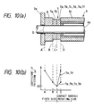
- FIGS. 10 to 15 show each embodiment of the assembly of the present invention with (a) being an explanatory main side sectional view, and (b) being a graph which illustrates frictional coefficients between the respective members in (a).
- FIG. 16 is an explanatory view of each slip disc to be used in the assembly of the present invention.
- reference numeral 1 generally represents a furnace body of a heat treatment furnace in which a reducing, combustible atmospheric gas containing hydrogen gas is used as a furnace gas 12 for continuously annealing, stress relieving annealing or otherwise heat treating a metallic strip S such as a stainless steel strip.
- the prevailing pressure is kept about 10 to about 50 mmH 2 O higher than the outside air by feeding the furnace gas 12 thereto.
- Reference numeral 2 stands for a furnace wall located at an entrance and exit of the furnace body 1 with the furnace gas 12 prevailing therein.
- Reference numeral 3 denotes a seal assembly for a heat treatment furnace using an atmospheric gas containing hydrogen-gas as the furnace gas 12 according to the present invention, said seal assemly being located at the entrance and/or exit of the furnace body 1 with the furnace gas 12 prevailing therein.
- the seal assembly 3 is built up of a seal plate 4 fixed on the furnace wall 2, a elastic pad 5 fixed on the seal plate 4, and an elastic rotating roll 6 to be engaged with the elastic pad 5 and metallic strip S, thereby sealing up the furnace body 1 for preventing a leakage of the furnace gas 12.
- the seal plate 4 for instance, is formed of a flexible, difficult-to-oxidize stainless steel thin sheet of about 0.5 to about 2.0 mm in thickness.
- An elastic pad 5 of felt etc. that is slightly, for instance, a few millimeters, longer than such gap length is fixed onto the surface of the short seal plate 4, using an adhesive material or a bolt-and-nut combination.
- the elastic rotating roll 6 must be of surface resiliency and so is formed of elastic members such as silicone rubber (ASTM Code Q and composed of an alkylsiloxane copolymer), fluororubber (ASTM Code FKM and composed of a hydrocarbon fluoride copolymer), chloroprene rubber (ASTM Code CR and composed of a chloroprene polymer), nitrile-butadiene rubber (ASTM Code NBR and composed of a butadiene-acrylonitrile copolymer), styrene-butadiene rubber (ASTM Code SBR and composed of a butadiene-styrene copolymer), ethylene-propylene rubber (ASTM Code EPDM and composed of an ethylene-propylene-diene copolymer), urethane rubber (ASTM Code U and composed of a polyesther (ether)-isocyanate polycondensate), hydrin rubber (ASTM Code CO and composed of an epchlorohydrin
- a plurality of closely arranged slip disks 7, each having a through-hole through which a roll shaft 6a of the elastic rotating roll 6 is to be passed, are located between a roll body 6c of the elastic rotating roll 6 and the side wall 2a of the furnace wall 2 and mounted around the roll shaft 6a.
- the slip disk 7 may be made of a plate material 7a with the contact surface having a low coefficient of dynamic friction and being difficult to wear off, for instance, a plate form of fluorocarbon resin such as polytetrafluoroethylene resin or fluorocoarbon resin such as polytetrafluoroethylene resin as the main component, and to improve wear resistance, rigidity and electrical conductivity, this plate form of fluorocarbon resin may contain a filler or fillers selected from the group of consisting of glass fiber, graphite, glass fiber plus molybdenum disulfide, glass fiber plus graphite, bronze, and carbon fiber.
- a filler or fillers selected from the group of consisting of glass fiber, graphite, glass fiber plus molybdenum disulfide, glass fiber plus graphite, bronze, and carbon fiber.
- a fluorocarbon resin only or a fluorocarbon resin with the filler is coated, sprayed, baked or the resin in a form of a sheet being pasted to the entire surface, including the inner, outer and both side surfaces of a metallic plate 7x.
- a fluorocarbon resin only or a fluorocarbon resin with the filler is coated, sprayed, baked or the resin in a form of a sheet being pasted on both sides of the metallic plate 7x.
- a fluorocarbon resin only or a fluorocarbon resin with the filler is coated, sprayed, baked or the resin in a form of a sheet being pasted to one side only of the metallic plate 7x proximate to the roll body 6c.
- a fluorocarbon resin only or a fluorocarbon resin with the filler is coated, sprayed, baked or the resin in a form of a sheet being pasted to one side only of the metallic plate 7x proximate to the wall 2a of the furnace wall 2 (reverse to the side of roll body 6e).
- a metallic plate having the metallic surface is formed.
- the outer diameter of this slip disk 7 has one-half the maximum thickness of the metallic strip S or more and is slightly smaller than that of the roll body 6c of the elastic rotating roll 6, provided that sealability can be well maintained.
- the elastic rotating roll 6 When the elastic rotating roll 6 is engaged with the elastic pad 5 and the metallic strip S, its outer diameter becomes smaller due to the deformation of its outer periphery but the slip disk 7 suffers from no deformation owing to its rigidity and so is substantially invariable in outer diameter. This is the reason for the slip disk 7 being made slightly smaller in outer diameter than the elastic rotating roll 6, whereby there is maintained sealability between the roll bodies 6c even while they are contacting each other.
- An elastic disk 8 is located on the side of the slip disk 7 that faces the side wall 2a of the furnace wall 2 while it is in contact with the slip disk 7.
- the elastic disk 8 is fitted over the roll shaft 6a of the elastic rotating roll 6, which is passed through a through-hole centrally formed therein.
- the surface of contact of the elastic disk 8 with the slip disk 7 [as shown by plane B in FIGS. 10(a) to 15(a)] has a coefficient of dynamic friction larger than that of the contact surfaces of the slip disks 7 [shown by plane C in FIGS. 10(a), 11(a) and 13(a)-15(a) and shown by plane C and plane D in FIG. 12(a)].
- This elastic disk 8 may be formed of a rubber material such as silicone rubber, fluororubber, chloroprene rubber, nitrile-butadiene rubber, styrene-butadiene rubber, ethylene-propylene rubber, urethane rubber, hydrin rubber, butyl rubber, isoprene rubber, butadiene rubber, chlorinated polyethylene, acrylic rubber, polysulfide rubber, and chlorosulfonated polyethylene.
- the rubber material used has a rubber hardenss of A40° to 60° as measured according to JIS K6301 (or corresponding to a rubber hardness of about 65 to about 80 as measured according to JIS K6050).
- an elastic member which has an expanding mechanism in the axial direction of the roll shaft with a fluid poured therein.
- an elastic member such as silicone rubber, fluororubber, chloroprene rubber, nitrile-butadiene rubber, styrene-butadiene rubber, ethylene-propylene rubber, urethane rubber, hydrin rubber, butyl rubber, isoprene rubber, butadiene rubber, chlorinated polyethylene, acrylic rubber, polysulfide rubber, and chlorosulfonated polyethylene, etc.
- an elastic disk shown at 8a in FIG. 13(a) should be restrained from rotation the side of side plate 2a of the furnace wall 2 because the inlet port is connected with a fluid conductor].
- Two or more such elastic disks 8 may be fitted over the roll shaft 6a, if they have no expanding mechanism. Anyhow, the elastic disk should have a rubber hardness large enough to enable the contact surface thereof to be in close contact with the roll with proper elasticity and, at the same time, the roll to rotate smoothly.
- the disk located proximately to the side wall 2a of the furnace wall 2 while being in contact therewith, may be elastic disk 8 as mentioned above; or a structure as shown in FIG. 9(a); or a slip disk 7e, 7c, 7b, 7a per see or which may be a sheet form of fluorocarbon resin such as polytetrafluoroethylene or a metallic sheet in which a fluorocarbon resin such as polytetrafluoroethylene as the main component added by a filler containing any one of glass fiber, graphite, glass fiber plus molybdenum disulfide, glass fiber plus graphite, bronze, and carbon fiber is coated, sprayed, baked, or a sheet being pasted on one or both sides thereof, or the entire surface thereof including the inner, outer and side surfaces; or an elastic disk 8 combined with the slip disks 7e, 7c, 7b, 7a in the end face of the roll.
- a slip disk 7e, 7c, 7b, 7a per see or which may be a sheet
- the slip disk 7 Since the slip disk 7 is bent outwardly of the furnace in the through-hole in the side wall 2a of the furnace wall 2 by the internal pressure generated from the elastic disk 8 as shown by a broken line F in FIG. 9(a), however, it is not preferable to use the surface of the side wall 2a of the furnace wall 2 as a sliding plane. In other words, it is preferable to use as the disk to be engaged with the side wall 2a of the furnace wall 2 the elastic disk 8 which need not entirely be rotated.
- the elastic disk 8 is slightly bulged out in the through-hole in the side wall 2a of the furnace wall 2 as shown by a broken line G in FIGS. 10(a) to 15(a), but there is no problem because it is disconnected from the rotating portion by the slip disk 7.
- the above-described slip disk 7 generates heat and softens due to its constant friction with the rotating of the elastic rotating roll 6.
- various fillers may be added thereto.
- Most of polytetrafluoroethylene resins are likely to be greatly charged with electricity, possibly resulting in spark discharge.
- the polytetrafluoroethylene resin used should have an electric resistivity value of 1 to 10 7 ⁇ cm. Any resin having an electric resistivity value exceeding 10 7 ⁇ cm is not preferable because it is substantially equivalent to an insulating substance and so is greatly charged with static electricity. Any resin having an electric resistivity lower than 1 ⁇ cm, too, is not preferable due to its good conductivity.
- the elastic disk 8 have an electric resistivity of 1 to 10 7 ⁇ cm to prevent it from being charged with electricity for the same reasons as mentioned above.
- the elastic disk designed to rotate in unison with the elastic rotating roll 6, for instance, those located proximately to the roll body 6c, as shown in FIGS. 11(a), 13(a) and 15(a), because it is repeatedly engaged with or disengaged from the roll body 6c, and undergoes friction with the elastic pad 5 as well.
- Reference numeral 11 generally shows a roll-driving mechanism designed to engage the elastic rotating roll 6 with the metallic strip S and elastic pad 5, which is not herein explained because it is the same as a roll-driving mechanism used with the above-described conventional seal assembly.
- the present invention provides a seal assembly 3 located at an entrance and/or exit of a heat treatment furnace for heat treating a continuously fed metallic strip (S) using an atmospheric gas containing hydrogen gas in operating the heat treatment furnace and including an elastic rotating roll 6 which is engaged with an elastic pad 5 fixed on the surface of a seal plate 4 and the metallic strip (S) to seal the inside of the furnace against the outside air, wherein: at least two closely-set slip disks 7 arranged in an axial direction of the side of a roll body 6c and, at least one of the elastic discs 8 is engaged with the side plate 2a of the furnace wall 2, are fitted over a roll shaft 6a between the side plate 2a of the furnace wall 2 on which the elastic rotating roll 6 is rotatably mounted and the roll body 6c of the elastic rotating roll 6, the slip disk and said elastic disk being in surface contact with each other, and of the contact surfaces of the parts present from the roll body 6c to the side plate 2a of the furnace wall 2, the contact surface of the slip disks 7 and 7 has the lowest coefficient of
- At least two closely arranged slip disks 7 and elastic disks 8 are located in the described order on the side of the roll body 6c while they are brought in contact with each other, and of the contact surfaces of these disks, the contact surface of the slip disks 7 and 7 has the lowest coefficient of dynamic friction.
- the slip disks 7 because of consisting only of fluorocarbon resin or composed mainly of fluorocarbon resin which the slip disk is made of, the slip disk has a low coefficient of friction and so is very low in resistance to rotation. Moreover, since they are less wearable by slippage, they produces no or little swarf, so that the surface of the metallic strip S, which is required to be kept clean, cannot be stained. To add to this, they undergoes no change in the coefficient of friction due to wearing; so they can work under constantly invariable conditions.
- slip disks 7a and 7b located on the fixed side, all but the slip disk 7 that rotates following the elastic rotating roll 6 or is located proximately to the side of the roll body 6c, are entirely formed of an unfilled or filled fluorocarbon resin, including the inner surfaces of holes through which the roll shaft 6a is passed, as shown in FIGS. 16(a) and (b).
- Such slip disks 7a and 7b albeit coming into sliding friction with the roll shaft 6a, is decreased in terms of the wearing of the inner surfaces of the holes and resistance to rotation as well, because its coefficient of friction is low. Thus, the sealing properties of such sliding friction parts are much more improved.
- the elastic disk 8 can be located in place while sufficient compression force is applied thereto to seal the disks against the atmospheric gas. Even in this case, it is unlikely that the rotation of the roll body 6c of the elastic rotating roll 6 may be transmitted to the side plate 2a of the furnace wall 2. Since slippage mainly occurs on the contact surface between the slip disks 7 and 7 that are less wearable and have a low coefficient of dynamic friction, it is possible to inhibit a decrease in the sealing properties of the ends of the elastic roll body 6c.
- the seal assembly can be used in good sealing condition over an extended period of time with no need of making repairs not only on the elastic disk 8 and slip disks 7 located between the roll body 6c of the elastic rotation roll 6 and the side plate 2a of the furnace wall 2 but also on the elastic rotating roll 6 and the side plate 2a of the furnace wall 2.
- the slip disk 7 undergoing continuous friction is predominantly made of a fluorocarbon resin containing a filler selected from the group consisting of glass fiber, graphite, glass fiber plus molybdenum disulfide, glass fiber plus graphite, bronze, and carbon fiber, or is formed of a metallic plate 7x coated thereon with such a fluorocarbon resin
- the elastic disk 8 is made of silicone rubber, fluororubber, chloroprene rubber, nitrile-butadiene rubber, styrene-butadiene rubber, ethylene-propylene rubber, urethane rubber, hydrin rubber, butyl rubber, isoprene rubber, butadiene rubber, chlorinated polyethylene, acrylic rubber, polysulfide rubber, chlorosulfonated polyethylene.
- the disks 7 and 8 those having an electric resistivity value of 1 to 10 7 ⁇ cm are used. Since static electricity primarily caused by the friction of the parts is removed therefrom through the furnace body 1 that is grounded, the risk of explosion or fire due to the ignition by electrostatic sparks of the furnace gas 12 leaking out of the seal assemblies 3 located at the entrance and exit can be reduced to the minimum. To add to this, when the parts such as the elastic pad 5 fixed on the surface of the seal plate 4, and the roll body 6c of the elastic rotating roll 6 are cleaned or inspected, the risk of explosion or fire due to the ignition of the furnace gas leaking out of the seal assembly 3 which is caused by spark discharge of static electricity caused by friction of the clothes and charged in the body of the worker through the finger tips can be decreased to the minimum. Thus, the safety of the seal assembly can be much more improved.
- a disk having the ability to be axially expanded with the fluid injected as shown at 8a in FIG. 13(a) is used as the elastic disk 8 to be engaged with the side plate 2a of the furnace wall 2. Even when it is worn away by a slippage on the contact surface, its width can be increased by a few milimeter by ten by regulating the pressure of the fluid injected, as desired, whereby a drop of the sealing properties of the ends of the elastic rotating roll 6 can be prevented.
- the present seal assemblies for the entrance and exit of heat treatment furnaces using an atmospheric gas containing hydrogen gas have a number of benefits and so is of great industrial value.
Abstract
Description
- The present invention relates to a seal assembly having an improved sealability, which is used at an entrance and/or exit of a heat treatment furnace for annealing, stress relieving annealing or otherwise heat treating a metallic strip such as a stainless steel or high alloy strip with no formation of oxide films on the surface thereof, using a reducing, combustible atmospheric gas containing hydrogen gas as a furnace gas, thereby isolating the inside of the furnace from the outside air.
- In a heat treatment furnace for annealing, stress relieving annealing or otherwise heat treating a metallic strip such as a stainless steel or high alloy strip while no oxide film is formed on the surface thereof, a combustible, reducing atmospheric gas such as a mixed gas consisting of 75% of hydrogen gas and 25% of nitrogen gas (hereinafter called simply the furnace gas) is fed into the furnace.
- An assembly for isolating the inside of the furnace from the outside air is usually mounted on portions of the entrance and/or exit thereof through which the metallic strip is to be passed, thereby preventing mixing of the outside air with the furnace gas (hereinafter called sealing). A typical example of such a seal assembly is disclosed in Japanese Patent Publication No. 42(1967)-18893. As disclosed, this seal assembly is built up of elastic rotating rolls for holding therebetween a metallic strip continuously fed into the furnace, said rolls rotating at a speed substantially equal to the feed speed of the metallic strip, a flexible seal plate fixed at ends to the furnace body, and felt or other elastic pads for making seals between the seal plate and the elastic rotating rolls.
- One example of a conventional heat treatment furnace for heat treating a metallic strip continuously fed there into using an atmospheric gas containing hydrogen gas as a furnace gas will now be explained generally with reference to a shaft type of a bright annealing furnace for annealing a stainless steel strip or other high alloy strip.
- FIG. 3 is a schematic view of the general structure of a shaft type of bright annealing furance for a stainless steel strip etc. A metallic strip S is guided by a bottom roll into the furnace through a
seal assembly 13 located on the entrance side of of a furnace body 1, where it is heated to a predetermined temperature, then cooled and finally annealed as desired. The thus treated strip is then fed out of the furnace through aseal assembly 13 located on the exit side. Usually, a reducing,combustible furnace gas 12 containing hydrogen gas is continuously fed into the furnace while it is cooled and circulated through, so that the inside pressure of the furnace can be kept an about 10 to about 50 mmH2O higher than the outside air. It is here to be noted that while the furnace is in operation, thefurnace gas 12 leaks little by little through theseal assemblies furnace gas 12. - FIGS. 4 and 5 are enlarged front and side views of a conventional seal assembly located on the exit side of the furnace respectively. FIG. 6 is an explanatory front view of a roll-driving mechanism in a conventional seal assembly. The conventional seal assembly, shown at 13, is of the structure wherein
elastic pads 15 formed of felt or a felt equivalent are fixed on the surfaces ofseal plates 14 secured on afurnace wall 2 by a bolt-and-nut combination, andelastic rotating rolls 16 with the surfaces made of elastic rubber are engaged with the metallic strip S andelastic pads 15 by the working force of apiston rod 11a driven by cylinder, so that the inside of the furnace 1 can be isolated from the outside air. - A brief account will here be given of a roll-
driving mechanism 11 for pressedly engaging theelastic rotating rolls 16 with theelastic pads 15 fixed on the surfaces of theseal plates 14 secured on thefurnace wall 2 and the metallic strip S by referring to FIGS. 4 to 6. Alever 11b is pivotally fixed on a fixedpin 11c that defines the center of rotation thereof. Thelever 11b is provided at its front end with a bearing 16b for supporting aroll shaft 16a of the elastic rotatingroll 16, with the rear end receiving the working force of thepiston rod 11a driven by the cylinder. The working force of thispiston rod 11a allows the twoelastic rotating rolls rolls elastic pads seal plates - In the above
conventional seal assembly 13, it has been proposed to attach aroll body 16c to theside plate 2a of thefurnace wall 2 through threewashers washers roll body 16c is tightly provided at one end with therubber washer 16d,friction washer 16e, andmetallic sealing washer 16f, or alternatively therubber washer 16d andmetallic sealing washer 16f, in order from the side of theroll body 16c. A closed-cell form of spongy neoprene is used for therubber washer 16d, fluorocarbon resin having a low wear rate (e.g., polytetrafluoroethylene resin) for thefriction washer 16e, and carbon steel, stainless steel or non-ferrous metal for themetallic sealing washer 16f. - However, the
seal assembly 13 with the aboveelastic rotating roll 16 built in it has the following problems. - Referring to FIGS. 7(a) and (b), the
metallic sealing washer 16f comes in sliding contact with theside plate 2a of thefurnace wall 2 on a plane shown by A as shown in (7). The coefficient of friction varies largely between when greased and when not greased. The rotational force of the elastic rotatingroll 16 is transmitted to theside plate 2a of thefurnace wall 2 by the elasticity of therubber washer 16d. When fully greased, the sliding surface is defined by the plane A, but when insufficiently greased, the sliding surface is defined by a plane B on which themetallic sealing washer 16f comes in contact with thefriction washer 16e. When the plane B becomes the sliding surface, themetallic sealing washer 16f, which remains fixed, comes in contact with the rotatingroll shaft 16a, and this causes them to be mutually damaged and worn away, as shown in FIG. 7(c). As a result, the sealing properties of themetallic sealing washer 16f become worse, because the gap between theelastic rotation roll 16 and themetallic sealing washer 16f is widened or the gap between theelastic pad 15 and themetallic sealing washer 16f is widened. - Referring to FIGS. 8(a) and (b) of the conventional seal assembly, there is a large variation of the coefficient of friction as shown in (b) between when greased and when not greased, because the metal parts come in sliding contact with each other on a plane A, as in the case of FIG. 7. When fully greased, the sliding surface is defined by the plane A. When not sufficiently greased, however, the sliding surface is defined by any of planes A, B and C, because they have a close coefficient of friction. Usually, however, greasing cannot be applied to the entrance and exit of a heat treatment furnace such as a bright annealing furnace. So far, the metallic strip S has been pre-treated in a degreasing (cleansing) apparatus, because it is colored or stained by deposition of oil matter. Even though greasing should be restricted to the ends of the roll, the grease would be gradually transmitted to the middle of the roll, resulting in coloration or contamination and, hence, degradation, of the surface of the metallic strip S. Now consider the case where greasing is done but it is done insufficiently. When the sliding surface is defined by the plane A, the
metallic sealing washer 16f is brought into rotating, sliding contact with theframe 2, whereby they are mutually damaged. When the sliding contact is defined by the plane B, therubber washer 16d is drastically worn away. Besides, since rotational torque is transmitted to therubber washer 16d from the end surface sides of the roll while themetallic sealing washer 16f remains substantially fixed due to friction with theside plate 2a of thefurnace wall 2, therubber washer 16d remains braked on the plane B. Consequently, therubber washer 16d is torsionally distorted and so out of normal disk shape, whereby it is spaced away from the plane B or C, making the sealing properties of worse. When the sliding surface is defined by the plane C on which therubber washer 16d comes in contact with theroll body 16c, therubber washer 16d is rapidly worn away due to sliding contact with the lining material of the elastic rotatingroll 16 and with the metallic portion of the end of the roll. Besides, therubber washer 16d is torsionally distorted and so out of normal disk shape, as is the case where the sliding surface is defined by the plane B. On the plane B or C, themetallic sealing washer 16f remains substantially fixed due to friction with theside plate 2a of thefurnace wall 2 to define the fixed side. Themetallic sealing washer 16f comes in contact with the rotatingroll shaft 16a and with theside plate 2a of thefurnace wall 2 as well because the torque transmitted from the roll is larger than that in the case of FIG. 7, whereby they are mutually damaged and so worn away. Consequently, the sealing properties of the seal assembly become worse, as can be seen from FIG. 8(c). - In the seal assembly shown in FIG. 7, the rotating portion is usually separated by the contact planes B from the fixed portion, and the
metallic sealing washer 16f and the rotatingroll shaft 16a are brought into contact with each other and so mutually worn away. In the seal assembly shown in FIG. 8, sliding movement occurs on any one of the contact planes A, B and C. On the plane A theside plate 2a of thefurnace wall 2 and themetallic sealing washer 16f are worn away, and by sliding movement on the plane B or C, therubber washer 16d per se is worn away while themetallic sealing washer 16f androll shaft 16a are brought into contact with each other and so mutually worn away. In other words, when the contact surface causing slippage is defined by a member other than thefriction washer 16e, the sealing properties of the seal assembly become worse, because it is worn away due to its poor wear resistance to form a gap. As a result, the amount of thefurnace gas 12 leaking out of the furnace increases with an increase in the consumption of the atmospheric gas. On fire, the seal assembly is heavily damaged. Frequent replacement of worn away parts is thus required. - However, even when at least one of the worn-away
washers roll body 16c of the elastic rotatingroll 16 is replaced, it is required for safety's sake that the feeding of the metallic strip S be interrupted to cool the furnace body 1 from within the furnace body 1, and that thefurnace gas 12 be expelled out by the injection of inactive gas such as nitrogen gas etc. This is very time-consuming and troublesome, and costs much as well. When the inner surface of theside plate 2a of thefurnace wall 2 is burnt away, bitten off or otherwise worn away to such an extent that smooth rotation is inhibited, it is also required to replace theside plate 2a of thefurnace wall 2 in its entirety or remove at least the elastic rotatingroll 16 from theside plate 2a of thefurnace wall 2 so that another reinforcement member can be attached to the inner surface of theside plate 2a of thefurnace wall 2. For safety's sake, it is then required that the feeding of the metallic strip S is interrupted and thefurnace gas 12 is removed from within the furnace body 1. This offers disadvantages preventing an easy operation thereof. - An object of the present invention can solve the above-mentioned conventional technical defects and provide a seal assembly of greater safety and improved efficiency and productivity, which is used with a heat treatment furnace using a furnace gas containing hydrogen gas, wherein a drop of the sealing properties caused by abrasion from damages and slippage between washers located at the ends of the roll body of the elastic rotating roll and mutual damages on the washers and the side plate of the furnace wall or a slippage therebetween is prevented, the sealing properties of the ends of the elastic rotating roll that rotates in synchronism with the moving metallic strip are in good condition, and the frequency of replacement of the elastic rotating roll and washers is decreased.
- In order to resolve the problems of the present invention, the present inventor has made research to find that upon the elastic roll rotated in association with the movement of the metallic strip, a slippage occurs between a rubber washer and a metallic sealing washer provided at the end of the roll body of the elastic rotating roll or the metallic sealing washer and the side plate of the furnace wall, whereby such parts are worn away and so decreased in service life, by noticing improved resistance to wear, wherein such a slippage is restricted to between parts having a low coefficient of friction and improved wear resistance based upon the coefficients of friction listed in FIG. 2 to be further explained later. Consequently, in a seal assembly located at an entrance and/or exit of a heat treatment furnace using an atmospheric gas containing hydrogen gas as furnace gas and including an elastic rotating roll which is engaged with an elastic pad fixed on the surface of a seal plate and the metallic strip to seal the inside of the furnace against the outside air, if at least two axially and closely arranged slip disks and an elastic disk are fitted over a roll shaft between the side plate of the furnace wall, on which the elastic rotating roll is rotatably mounted, and a roll body of the elastic rotating roll, said disks being in surface contact with each other. Of the contact surfaces of the parts present from the roll body to the side plate of the furnace wall, the contact surface of the slip disks has the lowest coefficient of dynamic friction. Thus, a slippage occurs predominantly between the closely arranged slip disks while rotating portion and fixed portion are spaced away from each other on both sides of said slip disks, so that the transmission of the rotation of the elastic rotating roll in association with the movement of the metallic strip to the elastic disk provided on the side plate of the furnace wall can be prevented. This prevents the torsional distortion of the elastic disk and the wearing of the elastic disk, the side plate of the furnace wall, the roll shaft, and the end surfaces of the roll, resulting in prevention of a drop of the sealing properties and an increase in the service life of the elastic rotating roll and the side plate of the furnace wall.
- The seal assemblies used with a heat treatment furnace using an atomospheric gas containing hydrogen gas according to the present invention will now be explained at great length with reference to the accompanying drawings.
- FIG. 1 is a side elevational view of an end portion of an elastic rotating roll in one embodiment of the present invention. FIG. 2 is a graph which illustrates a general experimental range of frictional coefficients between materials to be used in the present invention. FIG. 3 is a schematic view of the general structure of a shaft type of bright annealing furnace for a stainless steel strip. FIG. 4 is an explanatory front sectional view of a conventional seal assembly which is disposed at exit side of the bright annealing furnace. FIG. 5 is a side elevational view of an end portion of an elastic rotating roll in a conventional seal assembly. FIG. 6 is an explanatory front view of a roll-driving mechanism in the conventional seal assembly. FIGS 7 and 8 show the conventional seal assembly with (a) being an explanatory main side sectional view, (b) being a graph which illustrates frictional coefficients between the respective members in (a), and (c) being an explanatory view which illustrates a worn state after the conventional seal assembly is used. FIG 9 shows a seal assembly outside the present invention with (a) being an explanatory main side sectional view, and (b) being a graph which illustrates frictional coefficients between the respective members in (a). FIGS. 10 to 15 show each embodiment of the assembly of the present invention with (a) being an explanatory main side sectional view, and (b) being a graph which illustrates frictional coefficients between the respective members in (a). FIG. 16 is an explanatory view of each slip disc to be used in the assembly of the present invention.
- Referring to the accompanying drawings, reference numeral 1 generally represents a furnace body of a heat treatment furnace in which a reducing, combustible atmospheric gas containing hydrogen gas is used as a
furnace gas 12 for continuously annealing, stress relieving annealing or otherwise heat treating a metallic strip S such as a stainless steel strip. In the furnace body 1, the prevailing pressure is kept about 10 to about 50 mmH2O higher than the outside air by feeding thefurnace gas 12 thereto. -
Reference numeral 2 stands for a furnace wall located at an entrance and exit of the furnace body 1 with thefurnace gas 12 prevailing therein. -
Reference numeral 3 denotes a seal assembly for a heat treatment furnace using an atmospheric gas containing hydrogen-gas as thefurnace gas 12 according to the present invention, said seal assemly being located at the entrance and/or exit of the furnace body 1 with thefurnace gas 12 prevailing therein. Theseal assembly 3 is built up of a seal plate 4 fixed on thefurnace wall 2, aelastic pad 5 fixed on the seal plate 4, and an elasticrotating roll 6 to be engaged with theelastic pad 5 and metallic strip S, thereby sealing up the furnace body 1 for preventing a leakage of thefurnace gas 12. - The seal plate 4, for instance, is formed of a flexible, difficult-to-oxidize stainless steel thin sheet of about 0.5 to about 2.0 mm in thickness. The seal plate 4, wider than the width of the metallic strip S to be heat treated but narrower than the space between both
side plates furnace wall 2, is fixed on thefurnace wall 2 by fixing means such as a bolt and nut combination. - An
elastic pad 5 of felt etc. that is slightly, for instance, a few millimeters, longer than such gap length is fixed onto the surface of the short seal plate 4, using an adhesive material or a bolt-and-nut combination. Both side edges of theelastic pad 5 so constructed that they project from the both side edges of the seal plate 4 to the bothside plates elastic pad 5 are slightly bent, the sealing properties of theseal assembly 3 can be so maintained that the furnace body can be well sealed against leakage of thefurnace gas 12 and penetration of the outside air into the furnace bocy. This can be obtained in the same manner by theelastic pad 5 made of rubber or the like. - The elastic rotating roll 6 must be of surface resiliency and so is formed of elastic members such as silicone rubber (ASTM Code Q and composed of an alkylsiloxane copolymer), fluororubber (ASTM Code FKM and composed of a hydrocarbon fluoride copolymer), chloroprene rubber (ASTM Code CR and composed of a chloroprene polymer), nitrile-butadiene rubber (ASTM Code NBR and composed of a butadiene-acrylonitrile copolymer), styrene-butadiene rubber (ASTM Code SBR and composed of a butadiene-styrene copolymer), ethylene-propylene rubber (ASTM Code EPDM and composed of an ethylene-propylene-diene copolymer), urethane rubber (ASTM Code U and composed of a polyesther (ether)-isocyanate polycondensate), hydrin rubber (ASTM Code CO and composed of an epchlorohydrin copolymer), butyl rubber (ASTM Code IIR and composed of an isobutylene-isoprene copolymer), isoprene rubber (ASTM Code and IR composed of synthetic isoprene rubber), butadiene rubber (ASTM Code BR and composed of a butadiene copolymer), chlorinated polyethylene (ASTM Code CM and composed of chlorinated polyethylene), acrylic rubber (ASTM Code ACM and composed of an acrylate ester copolymer), polysulfide rubber (ASTM Code T and composed of an alkylene sulfide polymer), and chlorosulfonated polyethylene (ASTM Code CSM and composed of chlorosulfonated polyethylene). Alternatively, the elastic rotating roll may be formed of a metallic roll member with the outer surface made of the above elastic member or material made of felt, etc.
- A plurality of closely arranged
slip disks 7, each having a through-hole through which aroll shaft 6a of the elasticrotating roll 6 is to be passed, are located between aroll body 6c of the elasticrotating roll 6 and theside wall 2a of thefurnace wall 2 and mounted around theroll shaft 6a. Theslip disk 7 may be made of aplate material 7a with the contact surface having a low coefficient of dynamic friction and being difficult to wear off, for instance, a plate form of fluorocarbon resin such as polytetrafluoroethylene resin or fluorocoarbon resin such as polytetrafluoroethylene resin as the main component, and to improve wear resistance, rigidity and electrical conductivity, this plate form of fluorocarbon resin may contain a filler or fillers selected from the group of consisting of glass fiber, graphite, glass fiber plus molybdenum disulfide, glass fiber plus graphite, bronze, and carbon fiber. To obtain theslip disk 7b, a fluorocarbon resin only or a fluorocarbon resin with the filler is coated, sprayed, baked or the resin in a form of a sheet being pasted to the entire surface, including the inner, outer and both side surfaces of ametallic plate 7x. To obtain theslip disk 7c, a fluorocarbon resin only or a fluorocarbon resin with the filler is coated, sprayed, baked or the resin in a form of a sheet being pasted on both sides of themetallic plate 7x. To obtain theslip disk 7d, a fluorocarbon resin only or a fluorocarbon resin with the filler is coated, sprayed, baked or the resin in a form of a sheet being pasted to one side only of themetallic plate 7x proximate to theroll body 6c. To obtain theslip disk 7e a fluorocarbon resin only or a fluorocarbon resin with the filler is coated, sprayed, baked or the resin in a form of a sheet being pasted to one side only of themetallic plate 7x proximate to thewall 2a of the furnace wall 2 (reverse to the side of roll body 6e). As to obtainingslip disk 7f, a metallic plate having the metallic surface is formed. The outer diameter of thisslip disk 7 has one-half the maximum thickness of the metallic strip S or more and is slightly smaller than that of theroll body 6c of the elasticrotating roll 6, provided that sealability can be well maintained. When the elasticrotating roll 6 is engaged with theelastic pad 5 and the metallic strip S, its outer diameter becomes smaller due to the deformation of its outer periphery but theslip disk 7 suffers from no deformation owing to its rigidity and so is substantially invariable in outer diameter. This is the reason for theslip disk 7 being made slightly smaller in outer diameter than the elasticrotating roll 6, whereby there is maintained sealability between theroll bodies 6c even while they are contacting each other. - An
elastic disk 8 is located on the side of theslip disk 7 that faces theside wall 2a of thefurnace wall 2 while it is in contact with theslip disk 7. Theelastic disk 8 is fitted over theroll shaft 6a of the elasticrotating roll 6, which is passed through a through-hole centrally formed therein. The surface of contact of theelastic disk 8 with the slip disk 7 [as shown by plane B in FIGS. 10(a) to 15(a)] has a coefficient of dynamic friction larger than that of the contact surfaces of the slip disks 7 [shown by plane C in FIGS. 10(a), 11(a) and 13(a)-15(a) and shown by plane C and plane D in FIG. 12(a)]. Thiselastic disk 8 may be formed of a rubber material such as silicone rubber, fluororubber, chloroprene rubber, nitrile-butadiene rubber, styrene-butadiene rubber, ethylene-propylene rubber, urethane rubber, hydrin rubber, butyl rubber, isoprene rubber, butadiene rubber, chlorinated polyethylene, acrylic rubber, polysulfide rubber, and chlorosulfonated polyethylene. Preferably, the rubber material used has a rubber hardenss of A40° to 60° as measured according to JIS K6301 (or corresponding to a rubber hardness of about 65 to about 80 as measured according to JIS K6050). Alternatively, use may be made of an elastic member which has an expanding mechanism in the axial direction of the roll shaft with a fluid poured therein. For example, an elastic member such as silicone rubber, fluororubber, chloroprene rubber, nitrile-butadiene rubber, styrene-butadiene rubber, ethylene-propylene rubber, urethane rubber, hydrin rubber, butyl rubber, isoprene rubber, butadiene rubber, chlorinated polyethylene, acrylic rubber, polysulfide rubber, and chlorosulfonated polyethylene, etc. may be centrally provided an expanding mechanism with an inlet port through which a fluid such as air or oil is to be fed into the elastic member [it is here to be noted that an elastic disk shown at 8a in FIG. 13(a) should be restrained from rotation the side ofside plate 2a of thefurnace wall 2 because the inlet port is connected with a fluid conductor]. Two or more suchelastic disks 8 may be fitted over theroll shaft 6a, if they have no expanding mechanism. Anyhow, the elastic disk should have a rubber hardness large enough to enable the contact surface thereof to be in close contact with the roll with proper elasticity and, at the same time, the roll to rotate smoothly. - The disk located proximately to the
side wall 2a of thefurnace wall 2 while being in contact therewith, may beelastic disk 8 as mentioned above; or a structure as shown in FIG. 9(a); or aslip disk elastic disk 8 combined with theslip disks slip disk 7 is bent outwardly of the furnace in the through-hole in theside wall 2a of thefurnace wall 2 by the internal pressure generated from theelastic disk 8 as shown by a broken line F in FIG. 9(a), however, it is not preferable to use the surface of theside wall 2a of thefurnace wall 2 as a sliding plane. In other words, it is preferable to use as the disk to be engaged with theside wall 2a of thefurnace wall 2 theelastic disk 8 which need not entirely be rotated. Theelastic disk 8 is slightly bulged out in the through-hole in theside wall 2a of thefurnace wall 2 as shown by a broken line G in FIGS. 10(a) to 15(a), but there is no problem because it is disconnected from the rotating portion by theslip disk 7. - The above-described
slip disk 7 generates heat and softens due to its constant friction with the rotating of the elasticrotating roll 6. To increase its rigidity and wear resistance, various fillers may be added thereto. Most of polytetrafluoroethylene resins are likely to be greatly charged with electricity, possibly resulting in spark discharge. Most preferably, the polytetrafluoroethylene resin used should have an electric resistivity value of 1 to 107 Ω·cm. Any resin having an electric resistivity value exceeding 107 Ω·cm is not preferable because it is substantially equivalent to an insulating substance and so is greatly charged with static electricity. Any resin having an electric resistivity lower than 1 Ω·cm, too, is not preferable due to its good conductivity. When theelastic pad 5 is cleaned or inspected, there is a fear of spark discharge resulting from static electricity charged in the body of the worker through the finger tips because of the rubbing of the work clothes or for other reasons. If one of the twoslip disks 7, proximate to theroll body 6c, such as one shown at 7f in FIGS. 14(a) and 15(a), is formed of a metallic plate having a metallic surface, such as one in FIG. 16(f), frictional discharge can then be avoided with a low coefficient of friction. This slip disk is unlikely to be charged with electricity in itself, but should preferably be spaced away from the human body or other charged part for the same reasons as mentioned above. It is also desired that theelastic disk 8 have an electric resistivity of 1 to 107 Ω·cm to prevent it from being charged with electricity for the same reasons as mentioned above. In particular, this is true of the elastic disk designed to rotate in unison with the elasticrotating roll 6, for instance, those located proximately to theroll body 6c, as shown in FIGS. 11(a), 13(a) and 15(a), because it is repeatedly engaged with or disengaged from theroll body 6c, and undergoes friction with theelastic pad 5 as well. -
Reference numeral 11 generally shows a roll-driving mechanism designed to engage the elasticrotating roll 6 with the metallic strip S andelastic pad 5, which is not herein explained because it is the same as a roll-driving mechanism used with the above-described conventional seal assembly. - As hitherto mentioned, the present invention provides a
seal assembly 3 located at an entrance and/or exit of a heat treatment furnace for heat treating a continuously fed metallic strip (S) using an atmospheric gas containing hydrogen gas in operating the heat treatment furnace and including an elasticrotating roll 6 which is engaged with anelastic pad 5 fixed on the surface of a seal plate 4 and the metallic strip (S) to seal the inside of the furnace against the outside air, wherein:
at least two closely-setslip disks 7 arranged in an axial direction of the side of aroll body 6c and, at least one of theelastic discs 8 is engaged with theside plate 2a of thefurnace wall 2, are fitted over aroll shaft 6a between theside plate 2a of thefurnace wall 2 on which the elasticrotating roll 6 is rotatably mounted and theroll body 6c of the elasticrotating roll 6, the slip disk and said elastic disk being in surface contact with each other, and of the contact surfaces of the parts present from theroll body 6c to theside plate 2a of thefurnace wall 2, the contact surface of theslip disks roll body 6c of the elasticrotating roll 6 engaged with the metallic strip S can be rotated in alignment with the movement of the metallic strip S. Between theroll body 6c of the elasticrotating roll 6 and theside plate 2a of thefurnace wall 2, at least two closely arrangedslip disks roll body 6c slip with each other on the plane C in FIG. 10. Thus, no slippage occurs on the contact surface between theroll body 6c and theslip disk 7 orelastic disk 8 attached adjacent thereto, [the plane D in FIG. 10(a); other embodiments of the planes D and E in FIGS. 11(a), 13(a) and 15(a); the plane E in FIG. 12(a); and the plane D in FIG. 14(a)] and on the contact surface between theside plate 2a of thefurnace wall 2 and the disk [theelastic disk 8 of the embodiment in FIG. 1] located adjacent thereto [the planes A and B in FIG. 10(a) and the planes A and B in FIG. 11(a) to 15(a) showing other embodiments]. - In other words, at least two closely arranged
slip disks 7 andelastic disks 8 are located in the described order on the side of theroll body 6c while they are brought in contact with each other, and of the contact surfaces of these disks, the contact surface of theslip disks roll body 6c is rotated in alignment with the movement of the metallic strip S, the rotation of theroll body 6c is transmitted to theslip disks 7. Then, theslip disks roll body 6c to theelastic disk 8 located on the side of theside plate 2a of thefurnace wall 2 can be avoided. Consequently, no slippage occurs on the contact surfaces exclusive of that between theslip disks roll body 6c of the elasticrotating roll 6, theelastic disk 8 and theside plate 2a of thefurnace wall 2 can be avoided. Theslip disks 7, because of consisting only of fluorocarbon resin or composed mainly of fluorocarbon resin which the slip disk is made of, the slip disk has a low coefficient of friction and so is very low in resistance to rotation. Moreover, since they are less wearable by slippage, they produces no or little swarf, so that the surface of the metallic strip S, which is required to be kept clean, cannot be stained. To add to this, they undergoes no change in the coefficient of friction due to wearing; so they can work under constantly invariable conditions. This ensures that no disturbance is caused to fine tension control of the red-hot metallic strip S fed through the furnace, and that the power needed for the rotation of the elasticrotating roll 6 can be saved; that is, energy savings are achievable. In the present invention, it is preferable thatslip disks slip disk 7 that rotates following the elasticrotating roll 6 or is located proximately to the side of theroll body 6c, are entirely formed of an unfilled or filled fluorocarbon resin, including the inner surfaces of holes through which theroll shaft 6a is passed, as shown in FIGS. 16(a) and (b).Such slip disks roll shaft 6a, is decreased in terms of the wearing of the inner surfaces of the holes and resistance to rotation as well, because its coefficient of friction is low. Thus, the sealing properties of such sliding friction parts are much more improved. - Referring to the ability of the seal assembly to seal up the atmospheric gas containing hydrogen gas, the
elastic disk 8 can be located in place while sufficient compression force is applied thereto to seal the disks against the atmospheric gas. Even in this case, it is unlikely that the rotation of theroll body 6c of the elasticrotating roll 6 may be transmitted to theside plate 2a of thefurnace wall 2. Since slippage mainly occurs on the contact surface between theslip disks elastic roll body 6c. Thus, the seal assembly can be used in good sealing condition over an extended period of time with no need of making repairs not only on theelastic disk 8 and slipdisks 7 located between theroll body 6c of theelastic rotation roll 6 and theside plate 2a of thefurnace wall 2 but also on the elasticrotating roll 6 and theside plate 2a of thefurnace wall 2. - In the present invention, the
slip disk 7 undergoing continuous friction is predominantly made of a fluorocarbon resin containing a filler selected from the group consisting of glass fiber, graphite, glass fiber plus molybdenum disulfide, glass fiber plus graphite, bronze, and carbon fiber, or is formed of ametallic plate 7x coated thereon with such a fluorocarbon resin, and theelastic disk 8 is made of silicone rubber, fluororubber, chloroprene rubber, nitrile-butadiene rubber, styrene-butadiene rubber, ethylene-propylene rubber, urethane rubber, hydrin rubber, butyl rubber, isoprene rubber, butadiene rubber, chlorinated polyethylene, acrylic rubber, polysulfide rubber, chlorosulfonated polyethylene. As thedisks furnace gas 12 leaking out of theseal assemblies 3 located at the entrance and exit can be reduced to the minimum. To add to this, when the parts such as theelastic pad 5 fixed on the surface of the seal plate 4, and theroll body 6c of the elasticrotating roll 6 are cleaned or inspected, the risk of explosion or fire due to the ignition of the furnace gas leaking out of theseal assembly 3 which is caused by spark discharge of static electricity caused by friction of the clothes and charged in the body of the worker through the finger tips can be decreased to the minimum. Thus, the safety of the seal assembly can be much more improved. - Preferably, a disk having the ability to be axially expanded with the fluid injected as shown at 8a in FIG. 13(a) is used as the
elastic disk 8 to be engaged with theside plate 2a of thefurnace wall 2. Even when it is worn away by a slippage on the contact surface, its width can be increased by a few milimeter by ten by regulating the pressure of the fluid injected, as desired, whereby a drop of the sealing properties of the ends of the elasticrotating roll 6 can be prevented. - The present seal assemblies for the entrance and exit of heat treatment furnaces using an atmospheric gas containing hydrogen gas have a number of benefits and so is of great industrial value.
Claims (7)
- A seal assembly (3) located at an entrance and/or exit of a heat treatment furnace for heat treating a continuously fed metallic strip (S) using an atmospheric gas (12) containing hydrogen gas as a furnace gas and including an elastic rotating roll (6) which is engaged with an elastic pad (5) fixed on the surface of a seal plate (4) and the metallic strip (S) to seal the inside of the furnace against the outside air, characterized in that: at least two closely-set slip disks (7) arranged in an axial direction of the side of a roll body (6c) and, at least one of the elastic discs (8) is engaged with the side plate (2a) of the furnace wall (2), are fitted over a roll shaft 6a between the side plate (2a) of the furnace wall (2), on which the elastic rotating roll (6) is rotatably mounted, and the roll body (6c) of the elastic rotating roll (6), the slip disk and said elastic disk being in surface contact with each other, and of the contact surfaces of the parts present from the roll body (6c) to the side plate (2a) of the furnace wall (2), the contact surface of the slip disks (7) and (7) has the lowest coefficient of dynamic friction.
- The seal assembly for heat treatment furnace using an atmospheric gas containing hydrogen gas as recited in Claim 1,
wherein the slip disk (7) is made of a sheet form of fluorocarbon resin or a sheet form containing as the main component fluorocarbon resin added by a filler containing any one of glass fiber, graphite, glass fiber plus molybdenum disulfide, glass fiber plus graphite, bronze, and carbon fiber, or a sheet form of metal in which said fluorocarbon resin or said fluorocarbon resin with the filler is coated, sprayed, baked, or the materials in a form of sheet being pasted to one side or both sides thereof, or the entire surface thereof including the inner and outer and side surfaces. - The seal assembly for heat treatment furnace using an atmospheric gas containing hydrogen gas as recited in Claim 2, wherein the resinous portion of the surface of the slip disk (7) has an electric resistivity value of 1 to 107 Ω·cm.
- The seal assembly for heat treatment furnace using an atmospheric gas containing hydrogen gas as recited in any one of Claims 1 to 3 wherein at least two closely-set slip disks (7) arranged in an axially direction of the side of a roll body (6c), one slip disk (7) that is located proximately to the roll body (6c) is a slip disk (7f) made of a metallic plate having a metallic surface, or a slip disk (7d, 7e, 7c, 7b) in which materials containing only fluorocarbon resin or containing fluorocarbon resin as the main component added by a filler containing any one of glass fiber, graphite, glass fiber plus molybdenum disulfide, glass fiber plus graphite, bronze, and carbon fiber are coated, sprayed, baked, or the materials in a form of a sheet being pasted to one side or both sides of a metallic sheet (7x), or the entire surface thereof including the inner, outer and side surfaces thereof.
- The seal assembly for heat treatment furnace using an atmospheric gas containing hydrogen gas as recited in any one of Claims 1 to 4 wherein the elastic disk (8) is made of silicone rubber, fluororubber, chloroprene rubber, nitrile-butadiene rubber, styrene-butadiene rubber, ethylene-propylene rubber, urethane rubber, hydrin rubber, butyl rubber, isoprene rubber, butadiene rubber, chlorinated polyethylene, acrylic rubber, polysulfide rubber, and chlorosulfonated polyethylene.
- The seal assembly for heat treatment furnace using an atmospheric gas containing hydrogen gas as recited in any one of Claims 1 to 5 wherein the elastic disk (8) engaged with the side plate (2a) of the furnace wall (2) includes an expanding mechanism that is axially actuated by the pressure of a fluid to be injected.
- The seal assembly for heat treatment furnace using an atmospheric gas containing hydrogen gas as recited in any one of Claims 1 to 6 wherein the elastic disk (8) has an electric resistivity value of 1 to 107 Ω·cm.
Applications Claiming Priority (13)
| Application Number | Priority Date | Filing Date | Title |
|---|---|---|---|
| JP16490394 | 1994-06-24 | ||
| JP16490394 | 1994-06-24 | ||
| JP164903/94 | 1994-06-24 | ||
| JP16863994 | 1994-06-29 | ||
| JP168639/94 | 1994-06-29 | ||
| JP16863994 | 1994-06-29 | ||
| JP259779/94 | 1994-09-30 | ||
| JP25977994 | 1994-09-30 | ||
| JP25977994A JP2777873B2 (en) | 1994-06-29 | 1994-09-30 | Sealing device for heat treatment furnace using furnace atmosphere gas containing hydrogen gas |
| JP6284560A JP2834677B2 (en) | 1994-06-24 | 1994-10-26 | Sealing device for compartment entrance and exit of heat treatment furnace using atmosphere gas containing hydrogen gas |
| JP284560/94 | 1994-10-26 | ||
| JP28456094 | 1994-10-26 | ||
| EP95922745A EP0724019B1 (en) | 1994-06-24 | 1995-06-23 | Seal apparatus of heat-treatment furnace using furnace atmosphere gas containing hydrogen gas |
Related Parent Applications (2)
| Application Number | Title | Priority Date | Filing Date |
|---|---|---|---|
| EP95922745A Division EP0724019B1 (en) | 1994-06-24 | 1995-06-23 | Seal apparatus of heat-treatment furnace using furnace atmosphere gas containing hydrogen gas |
| EP95922745.5 Division | 1995-06-23 |
Publications (3)
| Publication Number | Publication Date |
|---|---|
| EP0743371A2 true EP0743371A2 (en) | 1996-11-20 |
| EP0743371A3 EP0743371A3 (en) | 1999-10-06 |
| EP0743371B1 EP0743371B1 (en) | 2001-09-12 |
Family
ID=27473958
Family Applications (2)
| Application Number | Title | Priority Date | Filing Date |
|---|---|---|---|
| EP95922745A Expired - Lifetime EP0724019B1 (en) | 1994-06-24 | 1995-06-23 | Seal apparatus of heat-treatment furnace using furnace atmosphere gas containing hydrogen gas |
| EP96112617A Expired - Lifetime EP0743371B1 (en) | 1994-06-24 | 1995-06-23 | Seal assembly for heat treatment furnaces using an atmospheric gas containing hydrogen gas |
Family Applications Before (1)
| Application Number | Title | Priority Date | Filing Date |
|---|---|---|---|
| EP95922745A Expired - Lifetime EP0724019B1 (en) | 1994-06-24 | 1995-06-23 | Seal apparatus of heat-treatment furnace using furnace atmosphere gas containing hydrogen gas |
Country Status (9)
| Country | Link |
|---|---|
| US (1) | US5693288A (en) |
| EP (2) | EP0724019B1 (en) |
| KR (1) | KR100191291B1 (en) |
| CN (2) | CN1043477C (en) |
| AT (2) | ATE205550T1 (en) |
| DE (3) | DE724019T1 (en) |
| ES (2) | ES2163559T3 (en) |
| TW (2) | TW307797B (en) |
| WO (1) | WO1996000307A1 (en) |
Cited By (2)
| Publication number | Priority date | Publication date | Assignee | Title |
|---|---|---|---|---|
| EP1179608A2 (en) | 2000-08-07 | 2002-02-13 | Nippon Steel Corporation | Fuel tank made of ferritic stainless steel |
| EP1193189A2 (en) * | 2000-09-29 | 2002-04-03 | Heidelberger Druckmaschinen Aktiengesellschaft | Shaft seal |
Families Citing this family (26)
| Publication number | Priority date | Publication date | Assignee | Title |
|---|---|---|---|---|
| JP2837367B2 (en) * | 1995-02-16 | 1998-12-16 | 日新製鋼株式会社 | Sealing device for compartment entrances such as continuous heat treatment furnaces and continuous vacuum deposition equipment |
| US6800172B2 (en) | 2002-02-22 | 2004-10-05 | Micron Technology, Inc. | Interfacial structure for semiconductor substrate processing chambers and substrate transfer chambers and for semiconductor substrate processing chambers and accessory attachments, and semiconductor substrate processor |
| US6814813B2 (en) | 2002-04-24 | 2004-11-09 | Micron Technology, Inc. | Chemical vapor deposition apparatus |
| US6858264B2 (en) * | 2002-04-24 | 2005-02-22 | Micron Technology, Inc. | Chemical vapor deposition methods |
| US6838114B2 (en) | 2002-05-24 | 2005-01-04 | Micron Technology, Inc. | Methods for controlling gas pulsing in processes for depositing materials onto micro-device workpieces |
| US6821347B2 (en) | 2002-07-08 | 2004-11-23 | Micron Technology, Inc. | Apparatus and method for depositing materials onto microelectronic workpieces |
| US6926775B2 (en) | 2003-02-11 | 2005-08-09 | Micron Technology, Inc. | Reactors with isolated gas connectors and methods for depositing materials onto micro-device workpieces |
| US7335396B2 (en) | 2003-04-24 | 2008-02-26 | Micron Technology, Inc. | Methods for controlling mass flow rates and pressures in passageways coupled to reaction chambers and systems for depositing material onto microfeature workpieces in reaction chambers |
| US7235138B2 (en) | 2003-08-21 | 2007-06-26 | Micron Technology, Inc. | Microfeature workpiece processing apparatus and methods for batch deposition of materials on microfeature workpieces |
| US7344755B2 (en) | 2003-08-21 | 2008-03-18 | Micron Technology, Inc. | Methods and apparatus for processing microfeature workpieces; methods for conditioning ALD reaction chambers |
| US7422635B2 (en) | 2003-08-28 | 2008-09-09 | Micron Technology, Inc. | Methods and apparatus for processing microfeature workpieces, e.g., for depositing materials on microfeature workpieces |
| US7056806B2 (en) | 2003-09-17 | 2006-06-06 | Micron Technology, Inc. | Microfeature workpiece processing apparatus and methods for controlling deposition of materials on microfeature workpieces |
| US7282239B2 (en) | 2003-09-18 | 2007-10-16 | Micron Technology, Inc. | Systems and methods for depositing material onto microfeature workpieces in reaction chambers |
| US7323231B2 (en) | 2003-10-09 | 2008-01-29 | Micron Technology, Inc. | Apparatus and methods for plasma vapor deposition processes |
| US7647886B2 (en) | 2003-10-15 | 2010-01-19 | Micron Technology, Inc. | Systems for depositing material onto workpieces in reaction chambers and methods for removing byproducts from reaction chambers |
| US7258892B2 (en) | 2003-12-10 | 2007-08-21 | Micron Technology, Inc. | Methods and systems for controlling temperature during microfeature workpiece processing, e.g., CVD deposition |
| US7906393B2 (en) * | 2004-01-28 | 2011-03-15 | Micron Technology, Inc. | Methods for forming small-scale capacitor structures |
| US7584942B2 (en) * | 2004-03-31 | 2009-09-08 | Micron Technology, Inc. | Ampoules for producing a reaction gas and systems for depositing materials onto microfeature workpieces in reaction chambers |
| US8133554B2 (en) | 2004-05-06 | 2012-03-13 | Micron Technology, Inc. | Methods for depositing material onto microfeature workpieces in reaction chambers and systems for depositing materials onto microfeature workpieces |
| US7699932B2 (en) | 2004-06-02 | 2010-04-20 | Micron Technology, Inc. | Reactors, systems and methods for depositing thin films onto microfeature workpieces |
| GB2462810B (en) * | 2008-08-18 | 2010-07-21 | Rolls Royce Plc | Sealing means |
| CN104673989B (en) * | 2014-11-26 | 2017-03-15 | 武汉钢铁(集团)公司 | A kind of continuous annealing furnace soaking zone air seal set and method |
| US11486030B2 (en) | 2018-05-23 | 2022-11-01 | Molecule Works Inc. | Process and apparatus for continuous production of porous structures |
| CN111396558B (en) * | 2020-03-23 | 2022-06-24 | 共享智能装备有限公司 | Sealing adjusting mechanism |
| CN111981858B (en) * | 2020-08-28 | 2022-01-28 | 费县沂州水泥有限公司 | Vertical type cement clinker pneumatic particle grading cooler and cooling method |
| CN113755682B (en) * | 2021-09-15 | 2022-10-21 | 江苏甬金金属科技有限公司 | Bright annealing furnace inlet sealing device |
Citations (2)
| Publication number | Priority date | Publication date | Assignee | Title |
|---|---|---|---|---|
| US2148093A (en) * | 1934-10-11 | 1939-02-21 | Harley T Wheeler | Rotary packing |
| US3291468A (en) * | 1965-05-05 | 1966-12-13 | Electric Furnace Co | Furnace seal means |
Family Cites Families (6)
| Publication number | Priority date | Publication date | Assignee | Title |
|---|---|---|---|---|
| US2367174A (en) * | 1942-08-10 | 1945-01-09 | Henry A Roemer | Seal for gas pickling furnace muffles |
| US3306594A (en) * | 1965-02-24 | 1967-02-28 | Crompton & Knowles Corp | Closed heat treating chamber having a seal roll oscillating mechanism |
| JPS4725762Y1 (en) * | 1969-09-10 | 1972-08-10 | ||
| US4168823A (en) * | 1977-06-27 | 1979-09-25 | Olin Corporation | Seals for the inlet and outlet of a continuous strip furnace |
| DE9112225U1 (en) * | 1991-10-01 | 1991-12-05 | Otto Junker Gmbh, 5107 Simmerath, De | |
| JPH0730412B2 (en) * | 1992-03-12 | 1995-04-05 | 中外炉工業株式会社 | In-furnace tension control device for vertical annealing furnace |
-
1995
- 1995-06-23 KR KR1019960700930A patent/KR100191291B1/en not_active IP Right Cessation
- 1995-06-23 WO PCT/JP1995/001256 patent/WO1996000307A1/en active IP Right Grant
- 1995-06-23 CN CN95190578A patent/CN1043477C/en not_active Expired - Lifetime
- 1995-06-23 EP EP95922745A patent/EP0724019B1/en not_active Expired - Lifetime
- 1995-06-23 US US08/596,170 patent/US5693288A/en not_active Expired - Lifetime
- 1995-06-23 ES ES96112617T patent/ES2163559T3/en not_active Expired - Lifetime
- 1995-06-23 DE DE0724019T patent/DE724019T1/en active Pending
- 1995-06-23 DE DE69522667T patent/DE69522667T2/en not_active Expired - Lifetime
- 1995-06-23 AT AT96112617T patent/ATE205550T1/en active
- 1995-06-23 DE DE69520203T patent/DE69520203T2/en not_active Expired - Lifetime
- 1995-06-23 ES ES95922745T patent/ES2091172T3/en not_active Expired - Lifetime
- 1995-06-23 EP EP96112617A patent/EP0743371B1/en not_active Expired - Lifetime
- 1995-06-23 AT AT95922745T patent/ATE199406T1/en active
- 1995-07-29 TW TW084107861A patent/TW307797B/zh not_active IP Right Cessation
- 1995-07-29 TW TW085103978A patent/TW403789B/en not_active IP Right Cessation
-
1996
- 1996-08-28 CN CN96109477A patent/CN1054643C/en not_active Expired - Lifetime
Patent Citations (2)
| Publication number | Priority date | Publication date | Assignee | Title |
|---|---|---|---|---|
| US2148093A (en) * | 1934-10-11 | 1939-02-21 | Harley T Wheeler | Rotary packing |
| US3291468A (en) * | 1965-05-05 | 1966-12-13 | Electric Furnace Co | Furnace seal means |
Cited By (3)
| Publication number | Priority date | Publication date | Assignee | Title |
|---|---|---|---|---|
| EP1179608A2 (en) | 2000-08-07 | 2002-02-13 | Nippon Steel Corporation | Fuel tank made of ferritic stainless steel |
| EP1193189A2 (en) * | 2000-09-29 | 2002-04-03 | Heidelberger Druckmaschinen Aktiengesellschaft | Shaft seal |
| EP1193189A3 (en) * | 2000-09-29 | 2004-05-06 | Heidelberger Druckmaschinen Aktiengesellschaft | Shaft seal |
Also Published As
| Publication number | Publication date |
|---|---|
| DE69520203D1 (en) | 2001-04-05 |
| EP0724019B1 (en) | 2001-02-28 |
| TW307797B (en) | 1997-06-11 |
| ATE205550T1 (en) | 2001-09-15 |
| CN1129959A (en) | 1996-08-28 |
| EP0724019A1 (en) | 1996-07-31 |
| DE69522667T2 (en) | 2002-06-20 |
| DE69520203T2 (en) | 2001-07-19 |
| ATE199406T1 (en) | 2001-03-15 |
| CN1043477C (en) | 1999-05-26 |
| CN1155585A (en) | 1997-07-30 |
| CN1054643C (en) | 2000-07-19 |
| KR100191291B1 (en) | 1999-06-15 |
| ES2091172T3 (en) | 2001-05-01 |
| EP0743371B1 (en) | 2001-09-12 |
| ES2091172T1 (en) | 1996-11-01 |
| EP0743371A3 (en) | 1999-10-06 |
| TW403789B (en) | 2000-09-01 |
| DE69522667D1 (en) | 2001-10-18 |
| ES2163559T3 (en) | 2002-02-01 |
| DE724019T1 (en) | 1997-01-30 |
| EP0724019A4 (en) | 1999-10-06 |
| WO1996000307A1 (en) | 1996-01-04 |
| US5693288A (en) | 1997-12-02 |
| KR960704076A (en) | 1996-08-31 |
Similar Documents
| Publication | Publication Date | Title |
|---|---|---|
| EP0743371B1 (en) | Seal assembly for heat treatment furnaces using an atmospheric gas containing hydrogen gas | |
| EP0770692B1 (en) | Sealing device for zone outlet/inlet of continuous heat treatment furnace, continuous vacuum evaporation equipment and the like | |
| CA1324168C (en) | Double jointed coolant seal | |
| JP2726242B2 (en) | Sealing device at the entrance or exit of atmosphere equipment | |
| US5791656A (en) | Seal assembly for heat treatment furnaces using an atmospheric gas containing hydrogen gas | |
| KR100196547B1 (en) | Sealing device for zone outlet-inlet for atmosphere equipment | |
| KR100236985B1 (en) | Seal apparatus of heat treatment furnace using furnace atmosphere gas containing hydrogen gas | |
| JP2763864B2 (en) | Sealing device at entrance and exit of atmosphere heat treatment furnace | |
| EP0721992B1 (en) | Method and apparatus for sealing at zone outlet/inlet of heat-treatment furnace using atmosphere gas containing hydrogen gas | |
| US5678831A (en) | Sealing device of compartment gateways of continuous annealing furnaces and continuous painting equipments | |
| JPH08266987A (en) | Seal device in demarcation entrance and exit of atmosphere equipment | |
| JP2794541B2 (en) | Sealing device for heat treatment furnace using atmosphere gas containing hydrogen gas | |
| JP2777873B2 (en) | Sealing device for heat treatment furnace using furnace atmosphere gas containing hydrogen gas | |
| JPH08193224A (en) | Seal device in inlet/outlet section of continuous heat treatment furnace using atmospheric gas in furnace containing gaseous hydrogen | |
| JPH0849985A (en) | Sealing method and apparatus for section inlet/outlet of heat treatment furnace using atmospheric gas containing hydrogen gas |
Legal Events
| Date | Code | Title | Description |
|---|---|---|---|
| PUAI | Public reference made under article 153(3) epc to a published international application that has entered the european phase |
Free format text: ORIGINAL CODE: 0009012 |
|
| AC | Divisional application: reference to earlier application |
Ref document number: 724019 Country of ref document: EP |
|
| AK | Designated contracting states |
Kind code of ref document: A2 Designated state(s): AT DE ES FR |
|
| PUAL | Search report despatched |
Free format text: ORIGINAL CODE: 0009013 |
|
| AK | Designated contracting states |
Kind code of ref document: A3 Designated state(s): AT DE ES FR |
|
| 17P | Request for examination filed |
Effective date: 19991103 |
|
| GRAG | Despatch of communication of intention to grant |
Free format text: ORIGINAL CODE: EPIDOS AGRA |
|
| 17Q | First examination report despatched |
Effective date: 20010110 |
|
| GRAG | Despatch of communication of intention to grant |
Free format text: ORIGINAL CODE: EPIDOS AGRA |
|
| GRAH | Despatch of communication of intention to grant a patent |
Free format text: ORIGINAL CODE: EPIDOS IGRA |
|
| GRAH | Despatch of communication of intention to grant a patent |
Free format text: ORIGINAL CODE: EPIDOS IGRA |
|
| GRAA | (expected) grant |
Free format text: ORIGINAL CODE: 0009210 |
|
| AC | Divisional application: reference to earlier application |
Ref document number: 724019 Country of ref document: EP |
|
| AK | Designated contracting states |
Kind code of ref document: B1 Designated state(s): AT DE ES FR |
|
| REF | Corresponds to: |
Ref document number: 205550 Country of ref document: AT Date of ref document: 20010915 Kind code of ref document: T |
|
| REF | Corresponds to: |
Ref document number: 69522667 Country of ref document: DE Date of ref document: 20011018 |
|
| ET | Fr: translation filed | ||
| REG | Reference to a national code |
Ref country code: ES Ref legal event code: FG2A Ref document number: 2163559 Country of ref document: ES Kind code of ref document: T3 |
|
| PLBE | No opposition filed within time limit |
Free format text: ORIGINAL CODE: 0009261 |
|
| STAA | Information on the status of an ep patent application or granted ep patent |
Free format text: STATUS: NO OPPOSITION FILED WITHIN TIME LIMIT |
|
| 26N | No opposition filed | ||
| PGFP | Annual fee paid to national office [announced via postgrant information from national office to epo] |
Ref country code: DE Payment date: 20140618 Year of fee payment: 20 Ref country code: ES Payment date: 20140513 Year of fee payment: 20 Ref country code: AT Payment date: 20140528 Year of fee payment: 20 |
|
| PGFP | Annual fee paid to national office [announced via postgrant information from national office to epo] |
Ref country code: FR Payment date: 20140609 Year of fee payment: 20 |
|
| REG | Reference to a national code |
Ref country code: DE Ref legal event code: R071 Ref document number: 69522667 Country of ref document: DE |
|
| REG | Reference to a national code |
Ref country code: AT Ref legal event code: MK07 Ref document number: 205550 Country of ref document: AT Kind code of ref document: T Effective date: 20150623 |
|
| REG | Reference to a national code |
Ref country code: ES Ref legal event code: FD2A Effective date: 20150930 |
|
| PG25 | Lapsed in a contracting state [announced via postgrant information from national office to epo] |
Ref country code: ES Free format text: LAPSE BECAUSE OF EXPIRATION OF PROTECTION Effective date: 20150624 |