EP0743098A2 - Nutationsregner - Google Patents
Nutationsregner Download PDFInfo
- Publication number
- EP0743098A2 EP0743098A2 EP96303475A EP96303475A EP0743098A2 EP 0743098 A2 EP0743098 A2 EP 0743098A2 EP 96303475 A EP96303475 A EP 96303475A EP 96303475 A EP96303475 A EP 96303475A EP 0743098 A2 EP0743098 A2 EP 0743098A2
- Authority
- EP
- European Patent Office
- Prior art keywords
- spray plate
- sprinkler
- ball bearings
- nozzle
- cap assembly
- Prior art date
- Legal status (The legal status is an assumption and is not a legal conclusion. Google has not performed a legal analysis and makes no representation as to the accuracy of the status listed.)
- Withdrawn
Links
Images


Classifications
-
- B—PERFORMING OPERATIONS; TRANSPORTING
- B05—SPRAYING OR ATOMISING IN GENERAL; APPLYING FLUENT MATERIALS TO SURFACES, IN GENERAL
- B05B—SPRAYING APPARATUS; ATOMISING APPARATUS; NOZZLES
- B05B3/00—Spraying or sprinkling apparatus with moving outlet elements or moving deflecting elements
- B05B3/008—Spraying or sprinkling apparatus with moving outlet elements or moving deflecting elements comprising a wobbling or nutating element, e.g. rotating about an axis describing a cone during spraying
-
- B—PERFORMING OPERATIONS; TRANSPORTING
- B05—SPRAYING OR ATOMISING IN GENERAL; APPLYING FLUENT MATERIALS TO SURFACES, IN GENERAL
- B05B—SPRAYING APPARATUS; ATOMISING APPARATUS; NOZZLES
- B05B3/00—Spraying or sprinkling apparatus with moving outlet elements or moving deflecting elements
- B05B3/02—Spraying or sprinkling apparatus with moving outlet elements or moving deflecting elements with rotating elements
- B05B3/04—Spraying or sprinkling apparatus with moving outlet elements or moving deflecting elements with rotating elements driven by the liquid or other fluent material discharged, e.g. the liquid actuating a motor before passing to the outlet
- B05B3/0417—Spraying or sprinkling apparatus with moving outlet elements or moving deflecting elements with rotating elements driven by the liquid or other fluent material discharged, e.g. the liquid actuating a motor before passing to the outlet comprising a liquid driven rotor, e.g. a turbine
- B05B3/0425—Spraying or sprinkling apparatus with moving outlet elements or moving deflecting elements with rotating elements driven by the liquid or other fluent material discharged, e.g. the liquid actuating a motor before passing to the outlet comprising a liquid driven rotor, e.g. a turbine actuated downstream of the outlet elements
- B05B3/0426—Spraying or sprinkling apparatus with moving outlet elements or moving deflecting elements with rotating elements driven by the liquid or other fluent material discharged, e.g. the liquid actuating a motor before passing to the outlet comprising a liquid driven rotor, e.g. a turbine actuated downstream of the outlet elements the liquid driven rotor being a deflecting rotating element
Definitions
- This invention relates to modular sprinkler devices and, more specifically, the invention relates to an improved sprinkler which incorporates a spray plate mounted for wobbling/rotating motion referred to herein as "nutation".
- Moving irrigation systems such as conventional pivot move (or center pivot) and lateral (or linear) move systems, are known to incorporate conduit truss span assemblies which mount sprinkler heads, spaced along the truss assemblies for sprinkling or irrigating relatively large areas of land.
- the sprinkling heads may be mounted on top of the truss assemblies in a normal upright position, or they may be inverted and suspended from the span assemblies by means of drop tubes.
- the sprinkler heads typically incorporate rotatable stream distributors (also referred to as rotor plates or spray plates), fixed spray plates or bubbler devices.
- U.S. Patent 5,439,174 discloses a modular sprinkler device which incorporates a spray plate mounted for wobbling/rotating motion, also referred to as nutation.
- the underside of the rotor or spray plate includes a central annular hub projecting from the underside of the plate.
- a shaft supports the spray plate at one end thereof and projects outwardly from the hub.
- the other end of the shaft receives a spherical ball which may be press fit or otherwise secured onto the shaft.
- the ball is received within a complementary spherical ball retainer cage secured to the cap assembly.
- This universal type mounting arrangement permits universal wobbling movement of the shaft about an axis extending through the nozzle and the center of the cap assembly as the ball moves within the cage.
- the periphery of the underside of the spray plate is formed with a plurality of gear teeth which are designed to mesh with a plurality of gear teeth provided on the interior surface of the otherwise stationary sprinkler cap assembly.
- 16 gear teeth are provided on the cap assembly and 15 gear teeth are provided on the underside of the spray plate.
- the rotor or spray plate As the water stream from the nozzle travels through the grooves in the spray plate, it causes the rotor or spray plate to nutate about the ball center. As the center of the rotor or spray plate wobbles in, for example, a counterclockwise direction of rotation, the perimeter of the rotor or spray plate is caused by the unequal number of gear teeth to advance step-wise (by one gear tooth per revolution) in a clockwise direction of rotation. By so controlling the nutating movement of the spray plate, uncontrolled spinning of the plate is prevented and a uniformly even sprinkling pattern is achieved.
- this invention it is the principal objective of this invention to employ a multi-stream rotor or spray plate that wobbles as it rotates in conjunction with a new and superior bearing arrangement. More specifically, the rotor or spray plate is free to move with reduced friction in a set motion through the use of a unique ball bearing arrangement where the spray plate mounting shaft is secured within the cap assembly. This arrangement is combined with continuous rolling contact between the rotating spray plate and the stationary cap assembly, about an annular surface of the spray plate, during nutation of the spray plate. This invention results in controlled nutating movement of the spray plate which causes the water streams to rotate consistently and fill in the sprinkling pattern uniformly.
- the sprinkler itself includes generally a sprinkler body, a removable cap assembly, a nozzle and a connector/adaptor.
- the cap assembly is modified to incorporate a rotor or spray plate which redirects a stream issuing from the fixed nozzle in a substantially radial direction by reason of a multi-groove configuration on a plate.
- These grooves are provided with combined radial and circumferential shape components (as opposed to only a radial component) so that the spray plate is caused to rotate when struck by the stream emitted from the nozzle.
- the underside of the rotor or spray plate includes a central annular hub projecting from the underside of the plate.
- a shaft supports the spray plate at one end thereof and projects outwardly from the hub.
- the other end of the shaft is formed with a part spherical head which is received within a complementary spherical ball retainer cage in the cap assembly.
- the part spherical shaft head engages three ball bearings in the cage of the sprinkler.
- An annular rim on the underside of the spray plate is formed with a bevelled surface (also referred to as a rotor ring) which rolls about a complementary bevelled surface (also referred to as a stator ring) on the interior of the otherwise stationary cap assembly as the spray plate nutates about the longitudinal axis of the sprinkler.
- a bevelled surface also referred to as a rotor ring
- a complementary bevelled surface also referred to as a stator ring
- the arrangement is such that the water stream exiting the nozzle impacts the tilted rotor/spray plate, travels through the grooves and exits the tilted rotor/spray plate on the outside diameter.
- the rotor/spray plate As the water stream travels through the grooves, it causes the rotor/spray plate to nutate (oscillate with an off center motion) about a common center of motion, i.e., the longitudinal axis of the sprinkler.
- the tilted rotor plate nutates, the nose of the plate oscillates in a clockwise motion, while the bevelled surface (or rotor ring) inside the skirt of the rotor plate rolls around the stator ring surface on the cap, in continuous contact.
- the circumference of the contact surface on the rotor plate is less than the circumference of the stator ring, however, and thus the rotor plate indexes counter-clockwise a distance equal to the difference of the circumferences.
- the point of contact between the rotor ring and the stator ring "walks" or "indexes” about the stator ring in one direction as the plate nutates about the longitudinal axis in an opposite direction.
- the present invention relates to a sprinkler comprising a body portion supporting a nozzle and a rotatable spray plate in axially spaced relationship to the nozzle, the spray plate having a mounting shaft formed with a part spherical head on an end thereof remote from the spray plate, the part spherical head received in a bearing cage containing a plurality of ball bearings.
- a sprinkler comprising a body portion having a nozzle at one end and a cap assembly supported thereon at an opposite end, the cap assembly supporting a spray plate located downstream of the nozzle, the spray plate having a plurality of stream distributing grooves formed on one side thereof configured to cause the spray plate to rotate when struck by a stream emitted from the nozzle; and wherein the spray plate includes a mounting shaft extending from the spray plate and having a part spherical head received within a bearing cage in the cap assembly, the bearing cage including a bearing separator holding a plurality of ball bearings in a substantially horizontal array arranged about a longitudinal center axis of the sprinkler, the part spherical head located centrally above and in engagement with the plurality of ball bearings, thereby permitting said spray plate to wobble as it rotates.
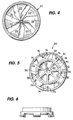
- the nutating sprinkler 10 in accordance with this invention includes generally, a sprinkler body 12, a removable cap assembly 14, a nozzle 16, and a connector/adaptor 18.
- the cap assembly 14 is an easily removable, positive latching type cap of the type disclosed in commonly owned U.S. Patent No. 5,409,168, incorporated herein by reference.
- the cap assembly 14, which is supported on a plurality of struts 15 extending from the body 14 (these equally spaced struts are employed, but only two are shown in Figure 1) is modified in this application however, to accommodate a rotor or spray plate 20 which redirects in a substantially radial direction, a stream issuing from the nozzle 16 by reason of the multi-groove configuration on the plate.
- the various grooves 22 (see also Figure 4) formed in the spray plate, are configured to cause the spray plate to rotate about a wobbling axis in a controlled manner as will be described in more detail below.
- the configuration of the grooves to include both radial and circumferential components to cause rotation of a spray plate is by itself, well known.
- the connector/adaptor 18 includes a male inlet end 24 provided with an external screw thread 26 adapted for connection to a pivot drop tube, supply pipe, hose or the like.
- the connector/adaptor 18 also includes a male outlet end 28 which is provided with an external discontinuous screw thread 30 adapted for threaded engagement with internal thread 32 in the inlet portion of the body 12.
- the nozzle 16 includes a central, tubular portion 34 defining a flow passage having an inlet 36 at one end and a discharge orifice 38 at an opposite, outlet end.
- the nozzle flow passage tapers inwardly at 40 from the inlet end of the nozzle to a midpoint of the flow passage, where the diameter remains constant until it reaches the discharge orifice 38 which is defined by a slightly enlarged radial shoulder 42.
- the outlet end includes an annular flange 44 formed with an annular groove 46 for receiving an 0-ring 48.
- Patent No. 5,415,348 also incorporated herein by reference.
- the nozzle assembly 16 as shown is of one-piece plastic construction. it will be appreciated however (and as shown in the '348 application), that the nozzle itself may be brass or other suitable material, fitted within the plastic web and ring structure.
- the underside of the plate i.e., that side opposite the side on which the water stream receiving grooves 22 are located, includes a cylindrically shaped annular hub 54 projecting from the undersurface of the plate.
- the hub 54 is essentially hollow, but with a spider configuration of radial webs 56 separated by wedge-like spaces 58.
- the webs 56 extend from a center bore 60 which receives a headed steel shaft 62.
- the shaft 62 includes a smooth shank portion 64, a splined portion 66 at one end and a part spherical head 68 at the opposite end.
- the splined portion 66 and most of the smooth shank are received within the bore such that the head 68 projects from the rear of the hub 54 as shown in Figures 1 and 2.
- a bevelled surface or rotor ring 70 which extends about the hub 54 radially between the hub and the undersurface of the plate.
- a radially outer depending skirt 72 surrounds and protects the rotor ring 70 from dirt and debris and, in this regard, note that the skirt 72 extends axially in a direction toward the head of the shaft, and beyond the ring 70.
- Annularly spaced recesses 74 formed in the undersurface of plate 20 (see Figure 5) and which extend into the areas between the water emitting grooves, save weight, while radial gussets 76 provide strength to the skirt.
- the cap assembly 20 incorporates a latch type securement mechanism of the type generally shown in commonly owned U.S. Patent No. 5,409,168, and this aspect of the cap need not be described in detail here.
- the significant aspects of the cap assembly 20 (best seen in Figures 1, 7 and 8) for purposes of this invention relate to the center structure which includes a cylindrical recess 78 which is defined by a cylindrical sleeve 79 formed integrally with the cap, and located concentrically relative to the longitudinal center axis.
- the sleeve 79 has a diameter greater than hub 54 so that the sleeve 79 loosely receives the hub 54 of the plate.
- the base of the recess 78 is formed with a raised center surface 80 having a central aperture 82 therein (see Figure 2) through which shaft 62 extends as shown in Figure 1, with the shaft head 68 lying on the other side of the center surface 80 (i.e., the shaft 62 is inserted into the spray plate 20 through the aperture 82).
- a second coaxial and generally cylindrical recess 84 is provided, which extends in an opposite direction from recess 78, from the underside 80' of surface 80, with annular wall 81 shaped to provide a series of radial steps or shoulders as described further below.
- the base of recess 84 is formed with a reduced diameter recess 86, defined by base 80' and axial wall portion 88.
- An annular, resilient lip seal 90 is seated within the recess 86, the seal having a center aperture 92 defined by a frusto-conical interior edge 94 which engages a bevelled surface 96 in base 80 surrounding the aperture 82.
- the lip seal 90 engages the shaft 62 substantially in the same plane as the center of motion of the spray plate 20, indicated by C in Figure 2. This arrangement minimizes wear on the lip seal in that the tilting oscillating movement of the shaft 62 is minimized at this location.
- the lip seal 90 is held in place by an annular seal retainer 98 which seats on radial surface 100, and which engages axial surface 102 as best seen in Figure 1.
- the retainer 98 may be press fit or otherwise secured in any appropriate manner.
- a ball bearing and separator assembly is seated in the recess or cage 84 with three balls 104, 106 and 108 seated in a disk-like separator 109 having three equi-spaced holes 110, 112 and 114 therein.
- Separator 109 seats on a radial surface 116 on the underside of a ball retainer cap 118 which is snap fit into place within the recess 84, with surface 116 cooperating with radial surface 120 to sandwich the separator 110 therebetween.
- the separator 109 prevents the otherwise freely movable balls 104, 106 and 108 from coming into contact with each other.
- the separator may be made of a polymer impregnated with solid lubricant so that during operation, the loose bearing balls where the separator and solid lubricant is thus wiped onto the balls, i.e., in a solid film transfer.
- balls 104, 106 and 108 are essentially free to rotate within the separator, the balls engaging an annular partially spherical surface 122 within the recess 84, and also engaging the similarly radiused, part spherical head 68 of the shaft 64.
- a horizontal plane through the center of ball bearings 104, 106 and 108 is vertically offset from a parallel horizontal plane through the center on which the radiused head 68 is drawn.
- the underside of cap assembly 14 mounts a stator or wear ring 124 in axial alignment with the sleeve 79.
- the inside diameter of the ring 124 is the same as the inside diameter of sleeve 79 such that the ring 124 essentially forms an axial extension of the sleeve.
- the ring 124 is snap fit into the cap assembly by means of a series of mounting tabs 126 arranged about the circumference of the ring, designed to be received in complementary apertures 128 (see Figures 7 and 8) formed in the cap assembly.
- the ring 124 is formed with a bevelled, annular wear or stator surface 130 (also referred to as the stator ring) which is engaged by rotor ring 70 of the rotator plate 20.
- a water stream exiting the nozzle 16 impacts the tilted rotor/spray plate 20 and travels through the grooves 22, exiting the plate on the outside diameter thereof.
- the rotor/spray plate 20 As the water stream travels through the grooves 22, it causes the rotor/spray plate 20 to nutate (oscillate with an off-center motion) about a common center of motion, i.e., the longitudinal center axis of the sprinkler.
- the nose of the plate 20 oscillates in, e.g., a clockwise direction.
- the part spherical shaft head 68 essentially orbits about the longitudinal axis, engaging the ball bearings 104, 106 and 108, and causing the latter to rotate and/or roll.
- the engagement between the head 68 and bearings 104, 106, 108 is essentially line contact (as in the case of tangential contact between two spheres) with all three bearings.
- the similarly radiused head 68 may be regarded as a "fourth ball". In the position shown in Figure 1, it can be seen that ball 106 has been caused to ride up on the ramp surface 122, and it will be understood that each ball will experience similar action, sequentially, as the shaft 64 nutates about the longitudinal axis.
- the radiused surface 122 is drawn from the center of the "fourth ball", i.e., the center of the part spherical head 68.
- This bearing arrangement is particularly advantageous insofar as friction and wear are significantly reduced, thus adding to the service life of the sprinkler.
- the bevelled surface or rotor ring 70 inside the skirt of the rotor plate 20 rolls around the stator ring 130 on the cap in continuous contact.
- the circumference of the rotor ring 70 is less than the circumference on the stator ring 130, and thus the rotor/spray plate 20 indexes counter-clockwise a distance equal to the difference of the circumferences, as the spray plate 20 nutates in the opposite direction.
Landscapes
- Nozzles (AREA)
Applications Claiming Priority (2)
| Application Number | Priority Date | Filing Date | Title |
|---|---|---|---|
| US08/446,099 US5588595A (en) | 1994-03-15 | 1995-05-19 | Nutating sprinkler |
| US446099 | 1995-05-19 |
Publications (2)
| Publication Number | Publication Date |
|---|---|
| EP0743098A2 true EP0743098A2 (de) | 1996-11-20 |
| EP0743098A3 EP0743098A3 (de) | 1997-02-05 |
Family
ID=23771315
Family Applications (1)
| Application Number | Title | Priority Date | Filing Date |
|---|---|---|---|
| EP96303475A Withdrawn EP0743098A3 (de) | 1995-05-19 | 1996-05-16 | Nutationsregner |
Country Status (3)
| Country | Link |
|---|---|
| US (1) | US5588595A (de) |
| EP (1) | EP0743098A3 (de) |
| AU (1) | AU691106B2 (de) |
Cited By (2)
| Publication number | Priority date | Publication date | Assignee | Title |
|---|---|---|---|---|
| ITVI20080175A1 (it) * | 2008-07-24 | 2010-01-25 | Arno Drechsel | Dispositivo diffusore di liquidi. |
| ITVI20130265A1 (it) * | 2013-10-29 | 2015-04-30 | Arno Drechsel | Dispositivo diffusore di liquidi per impianti di irrigazione |
Families Citing this family (64)
| Publication number | Priority date | Publication date | Assignee | Title |
|---|---|---|---|---|
| US5671885A (en) * | 1995-12-18 | 1997-09-30 | Nelson Irrigation Corporation | Nutating sprinkler with rotary shaft and seal |
| IL121726A (en) * | 1997-09-09 | 2001-09-13 | Mamtirim Dan | Strip pattern irrigating sprinkler |
| US5950927A (en) * | 1997-10-20 | 1999-09-14 | Senninger Irrigation, Inc. | Wobbling sprinkler head |
| US5971297A (en) * | 1997-12-03 | 1999-10-26 | Nelson Irrigation Corporation | Sprinkler with nozzle venturi |
| US6186414B1 (en) | 1998-09-09 | 2001-02-13 | Moen Incorporated | Fluid delivery from a spray head having a moving nozzle |
| US6092739A (en) * | 1998-07-14 | 2000-07-25 | Moen Incorporated | Spray head with moving nozzle |
| US6199771B1 (en) | 1998-11-16 | 2001-03-13 | Moen Incorporated | Single chamber spray head with moving nozzle |
| US6254014B1 (en) | 1999-07-13 | 2001-07-03 | Moen Incorporated | Fluid delivery apparatus |
| US6206216B1 (en) | 1999-07-26 | 2001-03-27 | Top Seal Corporation | Child-resistant cap |
| US6341733B1 (en) | 2000-02-03 | 2002-01-29 | Nelson Irrigation Corporation | Nutating sprinkler |
| US6439477B1 (en) | 2000-02-03 | 2002-08-27 | Nelson Irrigation Corporation | Nutating sprinkler |
| US6267299B1 (en) | 2000-04-05 | 2001-07-31 | Nelson Irrigation Corporation | Nutating sprinkler with gimbal bearing |
| US6820821B2 (en) | 2001-04-13 | 2004-11-23 | S.C. Johnson & Son, Inc. | Automated cleansing sprayer |
| US6719218B2 (en) | 2001-06-25 | 2004-04-13 | Moen Incorporated | Multiple discharge shower head with revolving nozzle |
| ITVI20020265A1 (it) | 2002-12-02 | 2004-06-03 | Arno Drechsel | Dispositivo diffusore, particolarmente per impianti di distribuzione a spruzzo di acqua ed altri liquidi similari. |
| US7025287B2 (en) * | 2003-08-14 | 2006-04-11 | Nelson Irrigation Corporation | Shaft seal with grease retainer |
| US7143957B2 (en) * | 2004-07-07 | 2006-12-05 | Nelson Irrigation Corporation | Two-axis full-circle sprinkler with bent, rotating nozzle |
| US7100842B2 (en) * | 2004-07-07 | 2006-09-05 | Nelson Irrigation Corporation | Two-axis full-circle sprinkler |
| US7278591B2 (en) * | 2004-08-13 | 2007-10-09 | Clearman Joseph H | Spray apparatus |
| EP1799355A1 (de) * | 2004-08-13 | 2007-06-27 | Joseph H. Clearman | Sprühvorrichtung und abgaberohre dafür |
| WO2006052624A1 (en) * | 2004-11-03 | 2006-05-18 | Nelson Irrigation Corporation | Water deflection assembly |
| US7261659B2 (en) * | 2005-04-22 | 2007-08-28 | Gm Global Technology Operations, Inc. | Electrically variable transmission having two planetary gearsets |
| ITVI20050155A1 (it) * | 2005-05-24 | 2006-11-25 | Arno Drechsel | Nuovo dispositivo diffusore, perticolarmente per impianti di distribuzione a spruzzo di liquidi o similari. |
| AU2007227242B2 (en) * | 2006-03-21 | 2011-12-08 | Nelson Irrigation Corporation | Water deflection subassembly |
| US7562833B2 (en) | 2006-07-21 | 2009-07-21 | Nelson Irrigation Corporation | Sprinkler with magnetic nutating mechanism and related method |
| US7287710B1 (en) | 2006-07-21 | 2007-10-30 | Nelson Irrigation Corporation | Sprinkler with magnetic nutating mechanism and related method |
| US8651400B2 (en) | 2007-01-12 | 2014-02-18 | Rain Bird Corporation | Variable arc nozzle |
| WO2008100527A1 (en) * | 2007-02-14 | 2008-08-21 | Nelson Irrigation Corporation | Fluid distributing device and method |
| IT1390781B1 (it) * | 2008-07-24 | 2011-09-23 | Arno Drechsel | Dispositivo diffusore di liquidi. |
| IT1390782B1 (it) * | 2008-07-24 | 2011-09-23 | Arno Drechsel | Dispositivo ad ugelli intercambiabili per la diffusione di liquidi. |
| US8028932B2 (en) * | 2009-04-01 | 2011-10-04 | Nelson Irrigation Corporation | Sprinkler with nutating mechanism and optional weight |
| AU2013202946A1 (en) * | 2008-08-14 | 2013-05-02 | Nelson Irrigation Corporation | Sprinkler with nutating mechanism and optional weight |
| US7942345B2 (en) | 2008-08-14 | 2011-05-17 | Nelson Irrigation Corporation | Sprinkler with nutating mechanism and optional weight |
| WO2010019850A2 (en) | 2008-08-14 | 2010-02-18 | Nelson Irrigation Corporation | Sprinkler with nutating mechanism and optional weight |
| US8074897B2 (en) | 2008-10-09 | 2011-12-13 | Rain Bird Corporation | Sprinkler with variable arc and flow rate |
| US8695900B2 (en) | 2009-05-29 | 2014-04-15 | Rain Bird Corporation | Sprinkler with variable arc and flow rate and method |
| US8925837B2 (en) | 2009-05-29 | 2015-01-06 | Rain Bird Corporation | Sprinkler with variable arc and flow rate and method |
| US8272583B2 (en) * | 2009-05-29 | 2012-09-25 | Rain Bird Corporation | Sprinkler with variable arc and flow rate and method |
| US8783582B2 (en) | 2010-04-09 | 2014-07-22 | Rain Bird Corporation | Adjustable arc irrigation sprinkler nozzle configured for positive indexing |
| US9504209B2 (en) | 2010-04-09 | 2016-11-29 | Rain Bird Corporation | Irrigation sprinkler nozzle |
| US9427751B2 (en) | 2010-04-09 | 2016-08-30 | Rain Bird Corporation | Irrigation sprinkler nozzle having deflector with micro-ramps |
| US8991724B2 (en) | 2012-06-06 | 2015-03-31 | Nelson Irrigation Corporation | Wobbling sprinkler with viscous brake |
| US9079202B2 (en) | 2012-06-13 | 2015-07-14 | Rain Bird Corporation | Rotary variable arc nozzle |
| US9174227B2 (en) | 2012-06-14 | 2015-11-03 | Rain Bird Corporation | Irrigation sprinkler nozzle |
| US9327297B2 (en) | 2012-07-27 | 2016-05-03 | Rain Bird Corporation | Rotary nozzle |
| US9295998B2 (en) | 2012-07-27 | 2016-03-29 | Rain Bird Corporation | Rotary nozzle |
| US9314952B2 (en) | 2013-03-14 | 2016-04-19 | Rain Bird Corporation | Irrigation spray nozzle and mold assembly and method of forming nozzle |
| US9387494B2 (en) * | 2013-10-10 | 2016-07-12 | Nelson Irrigation Corporation | Sprinkler with multi-functional, side-load nozzle insert with ball-type valve |
| US11020756B2 (en) | 2016-05-23 | 2021-06-01 | Nelson Irrigation Corporation | Orbital sprinkler with speed control brake |
| US10239066B2 (en) | 2016-05-23 | 2019-03-26 | Nelson Irrigation Corporation | Orbital sprinkler with speed control brake |
| US10322423B2 (en) | 2016-11-22 | 2019-06-18 | Rain Bird Corporation | Rotary nozzle |
| US11154877B2 (en) | 2017-03-29 | 2021-10-26 | Rain Bird Corporation | Rotary strip nozzles |
| US11511289B2 (en) | 2017-07-13 | 2022-11-29 | Rain Bird Corporation | Rotary full circle nozzles and deflectors |
| US10864534B2 (en) | 2017-08-21 | 2020-12-15 | Nelson Irrigation Corporation | Rigid mount orbitor sprinkler |
| US11040358B2 (en) | 2017-08-21 | 2021-06-22 | Nelson Irrigation Corporation | Rigid mount orbitor sprinkler with spider refuge |
| AU2019203003B2 (en) | 2018-07-18 | 2020-05-21 | Nelson Irrigation Corporation | Orbital sprinkler with speed control brake |
| AU2019206122B2 (en) | 2018-08-31 | 2020-07-09 | Nelson Irrigation Corporation | Rigid mount orbitor sprinkler with spider refuge |
| US11154882B2 (en) | 2018-12-11 | 2021-10-26 | Nelson Irrigation Corporation | Cage design with modified struts including oriented fins |
| US11000866B2 (en) | 2019-01-09 | 2021-05-11 | Rain Bird Corporation | Rotary nozzles and deflectors |
| US11059056B2 (en) | 2019-02-28 | 2021-07-13 | Rain Bird Corporation | Rotary strip nozzles and deflectors |
| US11406999B2 (en) | 2019-05-10 | 2022-08-09 | Rain Bird Corporation | Irrigation nozzle with one or more grit vents |
| US11247219B2 (en) | 2019-11-22 | 2022-02-15 | Rain Bird Corporation | Reduced precipitation rate nozzle |
| US12005464B2 (en) * | 2020-03-09 | 2024-06-11 | Xcad Valve And Irrigation, Inc. | Sprinkler with radially limited nutating spool assembly |
| US12582998B2 (en) | 2023-01-13 | 2026-03-24 | Hunter Agriculture Incorporated | Serviceable sprinkler with nutating distribution plate |
Family Cites Families (18)
| Publication number | Priority date | Publication date | Assignee | Title |
|---|---|---|---|---|
| US2639191A (en) * | 1950-04-10 | 1953-05-19 | Jr John O Hruby | Sprinkler head and nozzle |
| US2848276A (en) * | 1956-11-19 | 1958-08-19 | Jack F Clearman | Liquid distributor |
| US3009648A (en) * | 1958-07-07 | 1961-11-21 | Fmc Corp | Sprinkler head |
| US3034728A (en) * | 1960-06-20 | 1962-05-15 | Rain Jet Corp | Lawn sprinklers |
| US3312400A (en) * | 1964-09-15 | 1967-04-04 | Jack F Clearman | Pop-up sprinkler having a rotating head |
| GB1196746A (en) * | 1967-05-30 | 1970-07-01 | Terence Derwent Siddall | Improvements relating to Liquid Sprayers Particularly for Washing Apparatus. |
| US4073438A (en) * | 1976-09-03 | 1978-02-14 | Nelson Irrigation Corporation | Sprinkler head |
| US4290557A (en) * | 1980-02-25 | 1981-09-22 | Avner Rosenberg | Sprinklers |
| US4398666A (en) * | 1981-02-17 | 1983-08-16 | The Toro Company | Stream rotor sprinkler |
| US4486449A (en) * | 1981-07-31 | 1984-12-04 | Sumitomo Chemical Company, Limited | Thiocarbamate compounds, and their use |
| US4487368A (en) * | 1982-10-29 | 1984-12-11 | Clearman Jack F | Vane-driven wobbling sprinkler device |
| US4660766A (en) * | 1985-09-18 | 1987-04-28 | Nelson Irrigation Corporation | Rotary sprinkler head |
| US4796811A (en) * | 1988-04-12 | 1989-01-10 | Nelson Irrigation Corporation | Sprinkler having a flow rate compensating slow speed rotary distributor |
| FR2651451B1 (fr) * | 1989-09-07 | 1991-10-31 | Inst Francais Du Petrole | Appareil et installation pour le nettoyage de drains, notamment dans un puits de production petroliere. |
| US5224653A (en) * | 1992-01-31 | 1993-07-06 | Nelson Irrigation Corporation | Modular sprinkler assembly |
| US5381960A (en) * | 1993-08-23 | 1995-01-17 | Senninger Irrigation, Inc. | Wobbling irrigation sprinkler head including a magnet for initial tilt |
| US5415348A (en) * | 1993-08-31 | 1995-05-16 | Nelson Irrigation Corporation | Quick change and easily identifiable nozzle construction for use in modular sprinkler assembly |
| US5439174A (en) * | 1994-03-15 | 1995-08-08 | Nelson Irrigation Corporation | Nutating sprinkler |
-
1995
- 1995-05-19 US US08/446,099 patent/US5588595A/en not_active Expired - Fee Related
-
1996
- 1996-05-01 AU AU51982/96A patent/AU691106B2/en not_active Ceased
- 1996-05-16 EP EP96303475A patent/EP0743098A3/de not_active Withdrawn
Cited By (4)
| Publication number | Priority date | Publication date | Assignee | Title |
|---|---|---|---|---|
| ITVI20080175A1 (it) * | 2008-07-24 | 2010-01-25 | Arno Drechsel | Dispositivo diffusore di liquidi. |
| WO2010010534A1 (en) * | 2008-07-24 | 2010-01-28 | Arno Drechsel | Liquid diffuser device |
| US8590806B2 (en) | 2008-07-24 | 2013-11-26 | Arno Drechsel | Liquid diffuser device |
| ITVI20130265A1 (it) * | 2013-10-29 | 2015-04-30 | Arno Drechsel | Dispositivo diffusore di liquidi per impianti di irrigazione |
Also Published As
| Publication number | Publication date |
|---|---|
| AU5198296A (en) | 1996-11-28 |
| AU691106B2 (en) | 1998-05-07 |
| EP0743098A3 (de) | 1997-02-05 |
| US5588595A (en) | 1996-12-31 |
Similar Documents
| Publication | Publication Date | Title |
|---|---|---|
| US5588595A (en) | Nutating sprinkler | |
| US5439174A (en) | Nutating sprinkler | |
| AU721238B2 (en) | Nutating sprinkler with rotary shaft and seal | |
| US6341733B1 (en) | Nutating sprinkler | |
| US6439477B1 (en) | Nutating sprinkler | |
| EP2671645B1 (de) | Taumelsprinkler mit Viskosebremse | |
| EP1880768B1 (de) | Sprinkler mit magnetischem Taumelsystem und damit zusammenhängendes Verfahren | |
| US20080017732A1 (en) | Sprinkler with magnetic nutating mechanism and related method | |
| US6267299B1 (en) | Nutating sprinkler with gimbal bearing | |
| EP2227336B1 (de) | Behälterpistole mit doppelöffnungs-sprühkopf | |
| US5415348A (en) | Quick change and easily identifiable nozzle construction for use in modular sprinkler assembly | |
| US5224653A (en) | Modular sprinkler assembly | |
| US5762269A (en) | Nozzle clip | |
| US20100252654A1 (en) | Sprinkler with nutating mechanism and optional weight | |
| US4773594A (en) | Controlled pattern wobbling sprinkler | |
| EP0442862A1 (de) | Abschirmung für Sprühvorrichtung | |
| EP0142260B1 (de) | Rasensprenger | |
| US12005464B2 (en) | Sprinkler with radially limited nutating spool assembly | |
| US5918813A (en) | Rotating spray head | |
| US12582998B2 (en) | Serviceable sprinkler with nutating distribution plate | |
| US11154880B2 (en) | Nutating sprinkler head | |
| GB2296670A (en) | Spraying device | |
| EP0895814B1 (de) | Sich bewegende Fluid-Strahldüse | |
| CN120826282A (zh) | 用于灌溉系统的液体扩散装置 | |
| GB2288136A (en) | Rotary elements for liquid distribution |
Legal Events
| Date | Code | Title | Description |
|---|---|---|---|
| PUAI | Public reference made under article 153(3) epc to a published international application that has entered the european phase |
Free format text: ORIGINAL CODE: 0009012 |
|
| AK | Designated contracting states |
Kind code of ref document: A2 Designated state(s): ES FR |
|
| PUAL | Search report despatched |
Free format text: ORIGINAL CODE: 0009013 |
|
| AK | Designated contracting states |
Kind code of ref document: A3 Designated state(s): ES FR |
|
| 17P | Request for examination filed |
Effective date: 19970516 |
|
| 17Q | First examination report despatched |
Effective date: 20000327 |
|
| STAA | Information on the status of an ep patent application or granted ep patent |
Free format text: STATUS: THE APPLICATION IS DEEMED TO BE WITHDRAWN |
|
| 18D | Application deemed to be withdrawn |
Effective date: 20000808 |