EP0743049B1 - Artificial acetabular cup - Google Patents
Artificial acetabular cup Download PDFInfo
- Publication number
- EP0743049B1 EP0743049B1 EP95810329A EP95810329A EP0743049B1 EP 0743049 B1 EP0743049 B1 EP 0743049B1 EP 95810329 A EP95810329 A EP 95810329A EP 95810329 A EP95810329 A EP 95810329A EP 0743049 B1 EP0743049 B1 EP 0743049B1
- Authority
- EP
- European Patent Office
- Prior art keywords
- shell
- wire
- outer shell
- tunnel
- inner shell
- Prior art date
- Legal status (The legal status is an assumption and is not a legal conclusion. Google has not performed a legal analysis and makes no representation as to the accuracy of the status listed.)
- Expired - Lifetime
Links
Images


Classifications
-
- A—HUMAN NECESSITIES
- A61—MEDICAL OR VETERINARY SCIENCE; HYGIENE
- A61F—FILTERS IMPLANTABLE INTO BLOOD VESSELS; PROSTHESES; DEVICES PROVIDING PATENCY TO, OR PREVENTING COLLAPSING OF, TUBULAR STRUCTURES OF THE BODY, e.g. STENTS; ORTHOPAEDIC, NURSING OR CONTRACEPTIVE DEVICES; FOMENTATION; TREATMENT OR PROTECTION OF EYES OR EARS; BANDAGES, DRESSINGS OR ABSORBENT PADS; FIRST-AID KITS
- A61F2/00—Filters implantable into blood vessels; Prostheses, i.e. artificial substitutes or replacements for parts of the body; Appliances for connecting them with the body; Devices providing patency to, or preventing collapsing of, tubular structures of the body, e.g. stents
- A61F2/02—Prostheses implantable into the body
- A61F2/30—Joints
- A61F2/46—Special tools or methods for implanting or extracting artificial joints, accessories, bone grafts or substitutes, or particular adaptations therefor
- A61F2/4637—Special tools or methods for implanting or extracting artificial joints, accessories, bone grafts or substitutes, or particular adaptations therefor for connecting or disconnecting two parts of a prosthesis
-
- A—HUMAN NECESSITIES
- A61—MEDICAL OR VETERINARY SCIENCE; HYGIENE
- A61F—FILTERS IMPLANTABLE INTO BLOOD VESSELS; PROSTHESES; DEVICES PROVIDING PATENCY TO, OR PREVENTING COLLAPSING OF, TUBULAR STRUCTURES OF THE BODY, e.g. STENTS; ORTHOPAEDIC, NURSING OR CONTRACEPTIVE DEVICES; FOMENTATION; TREATMENT OR PROTECTION OF EYES OR EARS; BANDAGES, DRESSINGS OR ABSORBENT PADS; FIRST-AID KITS
- A61F2/00—Filters implantable into blood vessels; Prostheses, i.e. artificial substitutes or replacements for parts of the body; Appliances for connecting them with the body; Devices providing patency to, or preventing collapsing of, tubular structures of the body, e.g. stents
- A61F2/02—Prostheses implantable into the body
- A61F2/30—Joints
- A61F2/32—Joints for the hip
- A61F2/34—Acetabular cups
-
- A—HUMAN NECESSITIES
- A61—MEDICAL OR VETERINARY SCIENCE; HYGIENE
- A61F—FILTERS IMPLANTABLE INTO BLOOD VESSELS; PROSTHESES; DEVICES PROVIDING PATENCY TO, OR PREVENTING COLLAPSING OF, TUBULAR STRUCTURES OF THE BODY, e.g. STENTS; ORTHOPAEDIC, NURSING OR CONTRACEPTIVE DEVICES; FOMENTATION; TREATMENT OR PROTECTION OF EYES OR EARS; BANDAGES, DRESSINGS OR ABSORBENT PADS; FIRST-AID KITS
- A61F2/00—Filters implantable into blood vessels; Prostheses, i.e. artificial substitutes or replacements for parts of the body; Appliances for connecting them with the body; Devices providing patency to, or preventing collapsing of, tubular structures of the body, e.g. stents
- A61F2/02—Prostheses implantable into the body
- A61F2/30—Joints
- A61F2/46—Special tools or methods for implanting or extracting artificial joints, accessories, bone grafts or substitutes, or particular adaptations therefor
- A61F2/4603—Special tools or methods for implanting or extracting artificial joints, accessories, bone grafts or substitutes, or particular adaptations therefor for insertion or extraction of endoprosthetic joints or of accessories thereof
- A61F2/4609—Special tools or methods for implanting or extracting artificial joints, accessories, bone grafts or substitutes, or particular adaptations therefor for insertion or extraction of endoprosthetic joints or of accessories thereof of acetabular cups
-
- A—HUMAN NECESSITIES
- A61—MEDICAL OR VETERINARY SCIENCE; HYGIENE
- A61F—FILTERS IMPLANTABLE INTO BLOOD VESSELS; PROSTHESES; DEVICES PROVIDING PATENCY TO, OR PREVENTING COLLAPSING OF, TUBULAR STRUCTURES OF THE BODY, e.g. STENTS; ORTHOPAEDIC, NURSING OR CONTRACEPTIVE DEVICES; FOMENTATION; TREATMENT OR PROTECTION OF EYES OR EARS; BANDAGES, DRESSINGS OR ABSORBENT PADS; FIRST-AID KITS
- A61F2/00—Filters implantable into blood vessels; Prostheses, i.e. artificial substitutes or replacements for parts of the body; Appliances for connecting them with the body; Devices providing patency to, or preventing collapsing of, tubular structures of the body, e.g. stents
- A61F2/02—Prostheses implantable into the body
- A61F2/30—Joints
- A61F2002/30001—Additional features of subject-matter classified in A61F2/28, A61F2/30 and subgroups thereof
- A61F2002/30316—The prosthesis having different structural features at different locations within the same prosthesis; Connections between prosthetic parts; Special structural features of bone or joint prostheses not otherwise provided for
- A61F2002/30329—Connections or couplings between prosthetic parts, e.g. between modular parts; Connecting elements
- A61F2002/30331—Connections or couplings between prosthetic parts, e.g. between modular parts; Connecting elements made by longitudinally pushing a protrusion into a complementarily-shaped recess, e.g. held by friction fit
- A61F2002/30332—Conically- or frustoconically-shaped protrusion and recess
-
- A—HUMAN NECESSITIES
- A61—MEDICAL OR VETERINARY SCIENCE; HYGIENE
- A61F—FILTERS IMPLANTABLE INTO BLOOD VESSELS; PROSTHESES; DEVICES PROVIDING PATENCY TO, OR PREVENTING COLLAPSING OF, TUBULAR STRUCTURES OF THE BODY, e.g. STENTS; ORTHOPAEDIC, NURSING OR CONTRACEPTIVE DEVICES; FOMENTATION; TREATMENT OR PROTECTION OF EYES OR EARS; BANDAGES, DRESSINGS OR ABSORBENT PADS; FIRST-AID KITS
- A61F2/00—Filters implantable into blood vessels; Prostheses, i.e. artificial substitutes or replacements for parts of the body; Appliances for connecting them with the body; Devices providing patency to, or preventing collapsing of, tubular structures of the body, e.g. stents
- A61F2/02—Prostheses implantable into the body
- A61F2/30—Joints
- A61F2/32—Joints for the hip
- A61F2002/3241—Joints for the hip having a ring, e.g. for locking the femoral head into the acetabular cup
-
- A—HUMAN NECESSITIES
- A61—MEDICAL OR VETERINARY SCIENCE; HYGIENE
- A61F—FILTERS IMPLANTABLE INTO BLOOD VESSELS; PROSTHESES; DEVICES PROVIDING PATENCY TO, OR PREVENTING COLLAPSING OF, TUBULAR STRUCTURES OF THE BODY, e.g. STENTS; ORTHOPAEDIC, NURSING OR CONTRACEPTIVE DEVICES; FOMENTATION; TREATMENT OR PROTECTION OF EYES OR EARS; BANDAGES, DRESSINGS OR ABSORBENT PADS; FIRST-AID KITS
- A61F2/00—Filters implantable into blood vessels; Prostheses, i.e. artificial substitutes or replacements for parts of the body; Appliances for connecting them with the body; Devices providing patency to, or preventing collapsing of, tubular structures of the body, e.g. stents
- A61F2/02—Prostheses implantable into the body
- A61F2/30—Joints
- A61F2/46—Special tools or methods for implanting or extracting artificial joints, accessories, bone grafts or substitutes, or particular adaptations therefor
- A61F2/4603—Special tools or methods for implanting or extracting artificial joints, accessories, bone grafts or substitutes, or particular adaptations therefor for insertion or extraction of endoprosthetic joints or of accessories thereof
- A61F2002/4619—Special tools or methods for implanting or extracting artificial joints, accessories, bone grafts or substitutes, or particular adaptations therefor for insertion or extraction of endoprosthetic joints or of accessories thereof for extraction
-
- A—HUMAN NECESSITIES
- A61—MEDICAL OR VETERINARY SCIENCE; HYGIENE
- A61F—FILTERS IMPLANTABLE INTO BLOOD VESSELS; PROSTHESES; DEVICES PROVIDING PATENCY TO, OR PREVENTING COLLAPSING OF, TUBULAR STRUCTURES OF THE BODY, e.g. STENTS; ORTHOPAEDIC, NURSING OR CONTRACEPTIVE DEVICES; FOMENTATION; TREATMENT OR PROTECTION OF EYES OR EARS; BANDAGES, DRESSINGS OR ABSORBENT PADS; FIRST-AID KITS
- A61F2/00—Filters implantable into blood vessels; Prostheses, i.e. artificial substitutes or replacements for parts of the body; Appliances for connecting them with the body; Devices providing patency to, or preventing collapsing of, tubular structures of the body, e.g. stents
- A61F2/02—Prostheses implantable into the body
- A61F2/30—Joints
- A61F2/46—Special tools or methods for implanting or extracting artificial joints, accessories, bone grafts or substitutes, or particular adaptations therefor
- A61F2/4637—Special tools or methods for implanting or extracting artificial joints, accessories, bone grafts or substitutes, or particular adaptations therefor for connecting or disconnecting two parts of a prosthesis
- A61F2002/4641—Special tools or methods for implanting or extracting artificial joints, accessories, bone grafts or substitutes, or particular adaptations therefor for connecting or disconnecting two parts of a prosthesis for disconnecting
-
- A—HUMAN NECESSITIES
- A61—MEDICAL OR VETERINARY SCIENCE; HYGIENE
- A61F—FILTERS IMPLANTABLE INTO BLOOD VESSELS; PROSTHESES; DEVICES PROVIDING PATENCY TO, OR PREVENTING COLLAPSING OF, TUBULAR STRUCTURES OF THE BODY, e.g. STENTS; ORTHOPAEDIC, NURSING OR CONTRACEPTIVE DEVICES; FOMENTATION; TREATMENT OR PROTECTION OF EYES OR EARS; BANDAGES, DRESSINGS OR ABSORBENT PADS; FIRST-AID KITS
- A61F2220/00—Fixations or connections for prostheses classified in groups A61F2/00 - A61F2/26 or A61F2/82 or A61F9/00 or A61F11/00 or subgroups thereof
- A61F2220/0025—Connections or couplings between prosthetic parts, e.g. between modular parts; Connecting elements
- A61F2220/0033—Connections or couplings between prosthetic parts, e.g. between modular parts; Connecting elements made by longitudinally pushing a protrusion into a complementary-shaped recess, e.g. held by friction fit
Definitions
- the invention relates to an artificial joint shell with an outer shell and with an inner shell that with the outer shell has a common separating surface and the one in the outer shell with a clamp connection can be anchored, with the clamp connection through Friction between the inner shell and outer shell is formed.
- the invention further relates to a pull-out aid for pulling out an inner shell from an ance shell according to claim 5.
- Double artificial joint shells with one Snap connection between the outer and the inner Joint cups have been in use for many years.
- plastic inner shells the smaller one is used Rigidity of the plastic use to for Snap connections to achieve a positive fit.
- the plastic inner shells be when the plastic inner shell or a Pontic will be destroyed. It will be more difficult Situation when the inner and outer shell are made of metal, because the manufacturing tolerances for the pairing in the Clamping connection must be significantly less.
- Such an arrangement has the advantage that the Connection from inner shell to outer shell by one light blow when assembling and that even with large holding forces between the shells there is enough space through the tunnel to a uniform load along the inner shell of the bow when pulling out. So with one single cone angle for the self-locking connection Inner shells made of different materials and with different pulling forces in an outer shell be applied.
- the channel that forms the tunnel into the outer shell can be relocated.
- the Gutter to be attached to the inner shell.
- the conical self-locking connection still has that Advantage that inner shells with a raised edge on one side or with any other asymmetry in any Angle of rotation used in an implanted outer shell can be and by the relatively easy undressing in their angle of rotation can be corrected.
- the figures show an artificial joint shell with a outer shell implantable in a bone bed and a retrofittable inner shell that over a frictional clamping force, preferably by a self-locking conical connection, fixable to each other are.
- a tunnel is formed, which is arched to the Shell base connects two points on the edge of the shell.
- a wire can be inserted through the tunnel to the Inner shell without injury with an evenly over to pull out the arched pull-out force.
- an inner shell 3 is over a self-locking conical connection 5 with a Outer shell 2 connectable.
- a tunnel 6 in the assembled state generated that in an arc 37 to the base 7 out connects two points on the edge of the shell.
- the tunnel 6 will in this case by a groove 9 in the outer surface of the Inner shell 3 and formed by the separating surface 4; he can also be through a groove in the inner surface of the Outer shell 2 and through the parting surface 4 on the Inner shell 3 are formed.
- the wire 8 is elastic and bendable like a piano string wire or the multi-core pulling wire in a Bowden cable.
- the pull-out force is distributed over the Sheet 37 on the inner shell. Train can with fixed Pullers that are on the outer shell support, be generated or with a flexible Bowden cable whose guide jacket is on the outer shell supports.
- the principle is fixed Extracting device 10 shown that has a mounting body 20 owns that on both ends of the tunnel on the outer shell 2 seated with a foot 25.
- the wire 8 is on one Anchored with a head 13 in the attachment body 20, passed through the tunnel 6 of the joint socket and on the other side in a around a journal 21st pivoted clamping lever 17 held.
- the nip 11 is slightly corrugated. It arises through tightening a conical clamp 24 with one Clamping screw 23 with the help of an indicated Socket wrench 22. Because the clamping point 11 has a shorter distance from the journal 21 than the force application points on the much longer levers 16, 17, the pivoting movement is in a pivoting direction 18 stocky and a lower force necessary. At a simultaneous manual application of force to the levers 16, 17 the forces largely compensate and it hardly any additional forces arise between the Outer shell 2 and a surrounding bone bed. Around handling for inserting the wire 8 too facilitate, this is provided with a tip 12, the first without threading the body 20 Wire 8 in the tunnel 6 enables.
- the attachment device 20 has side slots 19 or recesses and a laterally open terminal point 11 to which already threaded wire 8 laterally into the extractor introduce.
- the edge of the inner shell 3 is shown in FIG. 6 provided with a recess 26 in the region of the channel 9, around the foot 25 of the extractor on the edge of the Center outer shell 2.
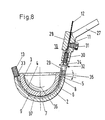
- FIG. 8 Another possibility for a pull-out device 10 is shown in Figure 8.
- a gutter 9 is in the Outer shell 2 and forms with the smooth inner shell 3 a tunnel 9.
- a wire 8 with tip 12 and head 13 is threaded directly.
- a bevel 33 forms with an angle 35 at the edge of the outer shell 2 an abutment for the head 13 and for a lower part 29 in the form of a Banjo bolt, which has a thread 30 in one
- Upper part 28 of the pull-out device 10 is screwed in.
- Upper and lower part 28, 29 are drawn in over the Wire 8 put over and this is with a clamping screw 31 clamped at a clamping point 11.
Abstract
Description
Die Erfindung handelt von einer künstlichen Gelenkschale mit einer Aussenschale und mit einer Innenschale, die mit der Aussenschale eine gemeinsame Trennfläche aufweist und die in der Aussenschale mit einer Klemmverbindung verankerbar ist, wobei die Klemmverbindung durch Reibschluss zwischen Innenschale und Aussenschale gebildet ist.The invention relates to an artificial joint shell with an outer shell and with an inner shell that with the outer shell has a common separating surface and the one in the outer shell with a clamp connection can be anchored, with the clamp connection through Friction between the inner shell and outer shell is formed.
Die Erfindung handelt ferner von einer Ausziehhilfe
zum Ausziehen einer Innenschale aus einer Anssenschale
gemäß Anspruch 5.The invention further relates to a pull-out aid
for pulling out an inner shell from an ance shell
according to
Doppelte künstliche Gelenkschalen mit einer Schnappverbindung zwischen der äusseren und der inneren Gelenkschale sind seit vielen Jahren in Gebrauch. Gerade bei Kunststoffinnenschalen macht man von der geringeren Steifigkeit des Kunststoffs Gebrauch, um für Schnappverbindungen einen Formschluss zu erreichen. So zeigt die Patentschrift EP 0 245 527 eine mit Reibung und Formschluss hergestellte Schnappverbindung einer Kunststofflagerschale in einer metallischen Aussenschale. Wegen der geringeren Steifigkeit des Kunststoffs wirken sich Schwankungen in den Herstellmassen bei der Paarung der beiden Teile nur geringfügig auf die Haltekräfte zwischen den beiden Schalen aus. Ausserdem können bei vielen Systemen die Kunststoffinnenschalen nur entfernt werden, wenn die Kunststoffinnenschale oder ein Zwischenglied zerstört werden. Schwieriger wird die Situation, wenn Innen- und Aussenschale aus Metall sind, da die Herstelltoleranzen für die Paarung in der Klemmverbindung wesentlich geringer sein müssen. Im weiteren muss bedacht werden, dass die Ausziehkräfte zum Entfernen einer Innenschale aus einer implantierten Aussenschale nicht so gross sein dürfen, dass der Sitz der implantierten Aussenschale im Knochen gefährdet wird. Abdrückschrauben zum Ausziehen oder Abdrücken der Innenschale sind nur dann möglich, wenn für das Ausziehen das Material der Innenschale und ihre Wandstärke das Anbringen von Gewindebohrungen gestatten, oder wenn für das Abdrücken die Innenschale mit einem Flansch mit Gewindebohrungen versehen ist. Gerade diese Bedingungen sind bei verschleissfesten Lagermaterialien wie z.B. Keramik oder harten Metallegierungen kaum erreichbar.Double artificial joint shells with one Snap connection between the outer and the inner Joint cups have been in use for many years. Just in the case of plastic inner shells, the smaller one is used Rigidity of the plastic use to for Snap connections to achieve a positive fit. So shows the patent EP 0 245 527 with friction and Form-fit snap connection of one Plastic bearing shell in a metallic outer shell. Because of the lower stiffness of the plastic fluctuations in the manufacturing masses during mating of the two parts only slightly on the holding forces between the two shells. In addition, at many systems only removed the plastic inner shells be when the plastic inner shell or a Pontic will be destroyed. It will be more difficult Situation when the inner and outer shell are made of metal, because the manufacturing tolerances for the pairing in the Clamping connection must be significantly less. in the Furthermore, it must be considered that the pull-out force for the Remove an inner shell from an implanted Outer shell must not be so big that the seat the implanted outer shell is endangered in the bone. Forcing screws to pull out or pull off the Inner shell are only possible if for taking off the material of the inner shell and its wall thickness Allow tapping, or if for pressing off the inner shell with a flange Threaded holes is provided. Precisely these conditions are used for wear-resistant bearing materials such as Ceramic or hard metal alloys hardly attainable.
In der EP-A-0 649 641 ist eine Gleitschale aus Keramik mit einem bestimmten Konuswinkel α in einer Metallschale verankert, um die Auspresskräfte niedrig zu halten. Die Kuppel der Keramikschale liegt hohl in der Kuppel der Metallschale, um die Konusverbindung nicht zu beeinflussen. Im Bereich der möglichen Konusklemmung sind zwei diametral gegenüberliegende Ausnehmungen in der Metallschale angebracht. Zum Heraushebeln der Gleitschale kann ein Ausdrückwerkzeug mit der Form eines Golfschlägers in einer der Ausnehmungen angesetzt werden. Diese Einrichtung hat den Nachteil, dass beim Heraushebeln eine einseitige Belastung am Rand einer implantierten Aussenschale auftreten kann, und dass eine punktförmige Belastungsspitze an der konischen Aussenfläche der Gleitschale entsteht, die zu keramischen Abplatzern innerhalb des Operationsfeldes führen kann.In EP-A-0 649 641 there is a ceramic sliding shell with a certain cone angle α in a metal shell anchored to keep the extrusion forces low. The Dome of the ceramic bowl lies hollow in the dome of the Metal shell to avoid the cone connection influence. In the area of possible cone clamping two diametrically opposite recesses in the Metal shell attached. For levering out the sliding shell can be an extraction tool with the shape of a Golf club can be placed in one of the recesses. This device has the disadvantage that the Pry out a one-sided load on the edge of one implanted outer shell can occur and that a punctiform load peak on the conical The outer surface of the sliding shell is created which is too ceramic Chipping within the operating field can result.
Es ist daher Aufgabe der Erfindung ein System zu
schaffen, das für verschiedene Materialkombinationen von
Aussenschale und Innenschale ein einfaches und schonendes
Lösen ihrer Verbindung gestattet. Diese Aufgabe wird mit
den Kennzeichen vom unabhängigen Anspruch 1 gelöst.It is therefore an object of the invention to provide a system
create that for different material combinations of
Outer shell and inner shell a simple and gentle
Disconnection allowed. This task comes with
solved the characteristic of
Eine solche Anordnung hat den Vorteil, dass die Verbindung von Innenschale zu Aussenschale durch einen leichten Schlag beim Zusammenfügen herstellbar ist und dass auch bei grossen Haltekräften zwischen den Schalen genügend Fläche durch den Tunnel vorhanden ist, die zu einer gleichmässigen Belastung der Innenschale entlang des Bogens beim Ausziehen führt. Somit können mit einem einzigen Konuswinkel für die selbsthemmende Verbindung Innenschalen aus unterschiedlichen Materialien und mit unterschiedlichen Ausziehkräften in einer Aussenschale angewendet werden.Such an arrangement has the advantage that the Connection from inner shell to outer shell by one light blow when assembling and that even with large holding forces between the shells there is enough space through the tunnel to a uniform load along the inner shell of the bow when pulling out. So with one single cone angle for the self-locking connection Inner shells made of different materials and with different pulling forces in an outer shell be applied.
Für schwer bearbeitbare oder dünnwandige Innenschalen kann die Rinne, die den Tunnel bildet in die Aussenschale verlegt werden. Bei dickwandigen Innenschalen kann die Rinne an der Innenschale angebracht werden.For hard-to-work or thin-walled inner shells can the channel that forms the tunnel into the outer shell be relocated. With thick-walled inner shells, the Gutter to be attached to the inner shell.
Dadurch, dass für das Ausziehen der Innenschale an dieser nur gleichmässig verteilte Druckkräfte auftreten, können auch spröde Werkstoffe für die Innenschalen verwendet werden. Im weiteren sind flanschlose und auf der Aussenseite rotationssymmetrische Innenschalen auf diese Weise verwendbar, was Fertigungsvorteile bei schwer bearbeitbaren Werkstoffen bringt. Als Ausziehhilfen eignen sich Zangen, die sich zur Verkürzung des im Tunnel liegenden Drahtbogens auf der Aussenschale abstützen. Ausziehkraft und Abstützkraft sind auf diese Weise über die Innenschale und die Ausziehvorrichtung kurzgeschlossen. Wenn eine an der Ausziehvorrichtung angreifende und nicht kompensierte restliche Einzelkraft notwendig ist, um eine Verkürzung des Drahtbogens vorzunehmen, kann diese Kraft, welche schlussendlich an der implantierten Aussenschale angreift, klein gehalten werden, sofern die mit der Kraft verbundene Bewegung kinematisch untersetzt ist.The fact that for pulling out the inner shell on this only evenly distributed pressure forces can occur brittle materials are also used for the inner shells become. In addition are flangeless and on the Outside, rotationally symmetrical inner shells on this Wise usable, which makes manufacturing difficult machinable materials. As undressing aids are suitable pliers that shorten the tunnel Support the arch wire on the outer shell. The pull-out force and support force are over in this way the inner shell and the pull-out device short-circuited. If one on the puller attacking and uncompensated residual individual force is necessary to shorten the arch wire can make this force, which ultimately attacks the implanted outer shell, kept small provided the movement associated with the force is kinematically reduced.
Die konische selbsthemmende Verbindung hat weiterhin den Vorteil, dass Innenschalen mit einseitig überhöhtem Rand oder mit einer sonstigen Asymmetrie in einem beliebigen Drehwinkel in einer implantierten Aussenschale eingesetzt werden können und durch das relativ einfache Ausziehen in ihrem Drehwinkel korrigiert werden können. The conical self-locking connection still has that Advantage that inner shells with a raised edge on one side or with any other asymmetry in any Angle of rotation used in an implanted outer shell can be and by the relatively easy undressing in their angle of rotation can be corrected.
Im folgenden wird die Erfindung anhand von Ausführungsbeispielen beschrieben. Es zeigen:
- Fig. 1
- schematisch eine Explosionszeichnung einer Innenschale mit Rinne, einen in dieser Rinne in einem Bogen durchgesteckten Ausziehdraht und eine entsprechende Aussenschale;
- Fig. 2
- schematisch die Elemente von
Figur 1 als Zusammenstellung; - Fig. 3
- schematisch ein Beispiel für eine Ausziehvorrichtung, die an einer implantierten Aussenschale angesetzt ist, um eine eingesetzte Innenschale auszuziehen;
- Fig. 4
- schematisch einen Schnitt IV in Fig. 3;
- Fig. 5
- schematisch einen Schnitt V in Fig. 3;
- Fig. 6
- schematisch einen vergrösserten Ausschnitt aus Fig. 4;
- Fig. 7
- schematisch einen vergrösserten Schnitt in Fig. 6;
- Fig. 8
- schematisch eine Ausziehvorrichtung mit einer Schraube zur Erzeugung der Ausziehkraft.
- Fig. 1
- schematically shows an exploded view of an inner shell with a gutter, a pull-out wire inserted in an arch in this gutter and a corresponding outer shell;
- Fig. 2
- schematically the elements of Figure 1 as a compilation;
- Fig. 3
- schematically an example of a pull-out device which is attached to an implanted outer shell in order to pull out an inserted inner shell;
- Fig. 4
- schematically a section IV in Fig. 3;
- Fig. 5
- schematically shows a section V in Fig. 3;
- Fig. 6
- schematically shows an enlarged section of Fig. 4;
- Fig. 7
- schematically shows an enlarged section in Fig. 6;
- Fig. 8
- schematically a puller with a screw to generate the pulling force.
Die Figuren zeigen eine künstliche Gelenkschale mit einer in einem Knochenbett implantierbaren Aussenschale und einer nachträglich einsetzbaren Innenschale, die über eine reibschlüssige Klemmkraft, vorzugsweise durch eine selbsthemmende konische Verbindung, zueinander fixierbar sind. In der Trennfläche zwischen den beiden Schalen wird ein Tunnel gebildet, welcher in einem Bogen zum Schalengrund hin zwei Punkte am Schalenrand verbindet. Durch den Tunnel kann ein Draht gesteckt werden, um die Innenschale ohne Verletzung mit einer gleichmässig über den Bogen verteilten Ausziehkraft herauszuziehen.The figures show an artificial joint shell with a outer shell implantable in a bone bed and a retrofittable inner shell that over a frictional clamping force, preferably by a self-locking conical connection, fixable to each other are. In the interface between the two shells a tunnel is formed, which is arched to the Shell base connects two points on the edge of the shell. A wire can be inserted through the tunnel to the Inner shell without injury with an evenly over to pull out the arched pull-out force.
In Figur 1 und 2 ist eine Innenschale 3 über eine
selbsthemmende konische Verbindung 5 mit einer
Aussenschale 2 verbindbar. In der Trennfläche 4 zwischen
den Schalen 2, 3 wird im montierten Zustand ein Tunnel 6
erzeugt, der in einem Bogen 37 zum Schalengrund 7 hin
zwei Punkte am Schalenrand verbindet. Der Tunnel 6 wird
in diesem Fall durch eine Rinne 9 in der Aussenfläche der
Innenschale 3 und durch die Trennfläche 4 gebildet; er
kann ebenso durch eine Rinne in der Innenfläche der
Aussenschale 2 und durch die Trennfläche 4 an der
Innenschale 3 gebildet werden. Der Draht 8 ist elastisch
und biegbar so wie ein Klaviersaitendraht oder der
mehradrige Zugdraht bei einem Bowdenzug. Wenn am Draht 8
relativ zur Aussenschale 2 in Ausziehrichtung 14 Zug
erzeugt wird, verteilt sich die Ausziehkraft über den
Bogen 37 an der Innenschale. Zug kann mit festen
Ausziehvorrichtungen, die sich auf der Aussenschale
abstützen, erzeugt werden oder auch mit einem flexiblen
Bowdenzug dessen Führungsmantel sich auf der Aussenschale
abstützt.In Figures 1 and 2, an
In den Figuren 3 bis 7 ist das Prinzip einer festen
Ausziehvorrichtung 10 gezeigt, die einen Aufsetzkörper 20
besitzt, der an beiden Tunnelenden auf der Aussenschale 2
mit einem Fuss 25 aufsitzt. Der Draht 8 ist auf der einen
Seite mit einem Kopf 13 im Aufsetzkörper 20 verankert,
durch den Tunnel 6 der Gelenkschale geführt und auf der
anderen Seite in einem um einen Lagerzapfen 21
schwenkbaren Klemmhebel 17 gehalten. In Figures 3 to 7, the principle is fixed
Extracting
Die Klemmstelle 11 ist leicht gewellt. Sie entsteht durch
das Festziehen eines konischen Klemmstücks 24 mit einer
Klemmschraube 23 mit Hilfe eines angedeuteten
Steckschlüssels 22. Dadurch, dass die Klemmstelle 11
einen kürzeren Abstand zum Lagerzapfen 21 aufweist als
die Kraftangriffspunkte an den wesentlich längeren Hebeln
16, 17, wird die Schwenkbewegung in einer Schwenkrichtung
18 untersetzt und eine geringere Kraft notwendig. Bei
einem gleichzeitigen manuellen Kraftangriff an den Hebeln
16, 17 kompensieren sich die Kräfte weitgehend und es
entstehen kaum zusätzliche Kräfte zwischen der
Aussenschale 2 und einem sie umgebenden Knochenbett. Um
die Handhabung für das Einführen des Drahtes 8 zu
erleichtern, ist dieser mit einer Spitze 12 versehen, die
zunächst ohne den Aufsetzkörper 20 das Einfädeln des
Drahtes 8 im Tunnel 6 ermöglicht. Die Aufsetzvorrichtung
20 besitzt seitliche Schlitze 19 oder Aussparungen und
eine seitlich offene Klemmstelle 11, um den bereits
eingefädelten Draht 8 seitlich in die Ausziehvorrichtung
einzuführen. In Figur 6 ist der Rand der Innenschale 3
mit einer Aussparung 26 im Bereich der Rinne 9 versehen,
um den Fuss 25 der Ausziehvorrichtung auf dem Rand der
Aussenschale 2 zu zentrieren.The
Eine weitere Möglichkeit für eine Ausziehvorrichtung 10
ist in Figur 8 gezeigt. Eine Rinne 9 befindet sich in der
Aussenschale 2 und bildet mit der glatten Innenschale 3
einen Tunnel 9. Ein Draht 8 mit Spitze 12 und Kopf 13
wird direkt eingefädelt. Dabei bildet eine Anschrägung 33
mit Winkel 35 am Rand der Aussenschale 2 ein Widerlager
für den Kopf 13 und für einen Unterteil 29 in Form einer
Hohlschraube, welche über ein Gewinde 30 in einem
Oberteil 28 der Ausziehvorrichtung 10 eingeschraubt ist.
Ober- und Unterteil 28, 29 werden über den eingezogenen
Draht 8 gestülpt und dieser wird mit einer Klemmschraube
31 an einer Klemmstelle 11 geklemmt. Mit einem nicht
gezeigten Gabelschlüssel, der auf einer Schulter 32
aufliegt und an Angriffsflächen 32 angreift wird nun der
Unterteil 29 herausgeschraubt und gleichzeitig Zug am
Draht erzeugt, um die Klemmverbindung 5 zwischen Innen-
und Aussenschale zu lösen. Ein Haltegriff 27 am Oberteil
28 sorgt dafür, dass zu dem Moment vom nicht gezeigten
Gabelschlüssel ein Gegenmoment erzeugt wird. Wegen der
nicht einfachen Platzverhältnisse kann statt dem Ober-
und Unterteil 28, 29 auch ein Bowdenzug verwendet werden,
dessen Mantelstück analog zum Unterteil 28 an der
Aussenschale aufliegt. Der Draht 8 ist dann entsprechend
länger ausgeführt.Another possibility for a pull-out
Ganz generell ist zu bemerken, dass der Bogen 37 nicht
durch die Polachse 36 der Innenschale 3 gelegt werden
muss, um ein Lösen der Klemmverbindung 5 zu bewirken.In general it should be noted that the
Claims (7)
- Artificial joint shell (1) having an outer shell (2) and an inner shell (3) , the inner shell having a partition surface (4) common to the outer shell and anchorable in the outer shell with a clamped connection (5), with the clamped connection being formed by friction locking between the inner shell (3) and the outer shell (2), characterised in that the inner shell (3) or the outer shell (2) has a channel (9) which forms a tunnel (6) with the opposite side in the partition surface (4) and which runs in an arc towards the shell base (7) from a point on the shell edge to another point on the shell edge in a direction, with a wire (8) being able to be passed through the tunnel (6) and with the inner shell (3) being able to be extracted from the outer shell (2) using the inserted wire (8).
- Artificial joint shell in accordance with claim 1, characterised in that the friction locking is formed by a self-locking, conical connection.
- Artificial joint shell in accordance with claim 1 or claim 2, characterised in that the inner shell is of metal.
- Artificial joint shell in accordance with claim 1 or claim 2, characterised in that the inner shell is of ceramic material.
- Extraction tool (10) for pulling an inner shell (3) out of an outer shell (2) in a joint shell in accordance with one of the claims 1 to 4, with the extraction tool having a wire (8) provided with a head (13) and a foot (25, 29) and being supportable on the edge of the outer shell in order to generate an extraction force on the wire (8) which can be passed through the tunnel (6).
- Extraction tool in accordance with claim 5, characterised in that it has means (13, 23, 24, 31) with which the wire passed through the tunnel (6) can be clamped in the extraction tool and in that it has further means (17, 21 16; 29, 30, 28) with which the wire length of the wire (8) passed through the tunnel (8) can be shortened.
- Extraction tool in accordance with claim 6, characterised in that the wire length inside the extraction tool (10) can be shortened by the movement of a clamping point (11), with the movement of the clamping point being geared down kinematically in order to avoid large external forces on actuation of the extraction tool.
Priority Applications (6)
| Application Number | Priority Date | Filing Date | Title |
|---|---|---|---|
| DE59509561T DE59509561D1 (en) | 1995-05-18 | 1995-05-18 | Artificial joint shell |
| EP95810329A EP0743049B1 (en) | 1995-05-18 | 1995-05-18 | Artificial acetabular cup |
| AT95810329T ATE204727T1 (en) | 1995-05-18 | 1995-05-18 | ARTIFICIAL JOINT SHELL |
| ES95810329T ES2163486T3 (en) | 1995-05-18 | 1995-05-18 | ARTIFICIAL ACETABULAR DOME. |
| US08/632,978 US5702476A (en) | 1995-05-18 | 1996-04-16 | Artificial joint shell |
| JP8120316A JPH08308867A (en) | 1995-05-18 | 1996-05-15 | Artificial joint shell |
Applications Claiming Priority (1)
| Application Number | Priority Date | Filing Date | Title |
|---|---|---|---|
| EP95810329A EP0743049B1 (en) | 1995-05-18 | 1995-05-18 | Artificial acetabular cup |
Publications (2)
| Publication Number | Publication Date |
|---|---|
| EP0743049A1 EP0743049A1 (en) | 1996-11-20 |
| EP0743049B1 true EP0743049B1 (en) | 2001-08-29 |
Family
ID=8221742
Family Applications (1)
| Application Number | Title | Priority Date | Filing Date |
|---|---|---|---|
| EP95810329A Expired - Lifetime EP0743049B1 (en) | 1995-05-18 | 1995-05-18 | Artificial acetabular cup |
Country Status (6)
| Country | Link |
|---|---|
| US (1) | US5702476A (en) |
| EP (1) | EP0743049B1 (en) |
| JP (1) | JPH08308867A (en) |
| AT (1) | ATE204727T1 (en) |
| DE (1) | DE59509561D1 (en) |
| ES (1) | ES2163486T3 (en) |
Families Citing this family (31)
| Publication number | Priority date | Publication date | Assignee | Title |
|---|---|---|---|---|
| DE19701536A1 (en) * | 1996-08-24 | 1998-02-26 | Cerasiv Gmbh | Joint prosthesis |
| GB2323036B (en) * | 1997-03-14 | 2001-04-11 | Finsbury | Prosthetic implant and surgical tool |
| IT1304410B1 (en) * | 1998-11-11 | 2001-03-19 | Samo Spa | EXTRACTOR FOR REMOVING THE BIOCERAMIC INSERT FROM THE ACETABULAR CUP OF A HIP PROSTHESIS AND ITS MODIFIED INSERT. |
| GB2360212A (en) * | 2000-02-15 | 2001-09-19 | Finsbury | Prosthetic implant and surgical tool |
| AU783205C (en) | 2000-03-15 | 2006-08-17 | Depuy Orthopaedics, Inc. | Prosthetic cup assembly which includes components possessing self-locking taper |
| GB0015855D0 (en) * | 2000-06-28 | 2000-08-23 | Univ London | Replacement of bearing surfaces for hip prosthesis |
| US7326253B2 (en) * | 2001-11-16 | 2008-02-05 | Depuy Products, Inc. | Prosthetic cup assembly having increased assembly congruency |
| WO2005013865A2 (en) * | 2003-08-07 | 2005-02-17 | Smith & Nephew, Inc. | Modified orthopaedic implants for improved sterilization |
| EP1721586B1 (en) * | 2005-05-12 | 2010-09-08 | Finsbury (Development) Limited | Cap and activation tool |
| US8157869B2 (en) | 2007-01-10 | 2012-04-17 | Biomet Manufacturing Corp. | Knee joint prosthesis system and method for implantation |
| US8187280B2 (en) | 2007-10-10 | 2012-05-29 | Biomet Manufacturing Corp. | Knee joint prosthesis system and method for implantation |
| US8163028B2 (en) | 2007-01-10 | 2012-04-24 | Biomet Manufacturing Corp. | Knee joint prosthesis system and method for implantation |
| US8328873B2 (en) | 2007-01-10 | 2012-12-11 | Biomet Manufacturing Corp. | Knee joint prosthesis system and method for implantation |
| US8562616B2 (en) | 2007-10-10 | 2013-10-22 | Biomet Manufacturing, Llc | Knee joint prosthesis system and method for implantation |
| DE102007051293B4 (en) * | 2007-10-23 | 2014-02-20 | Christian Arnhold | Universal razor for hip endoprostheses |
| US9539097B2 (en) | 2007-11-08 | 2017-01-10 | Linares Medical Devices, Llc | Hip and knee joint assemblies incorporating debris collection architecture between the ball and seat interface |
| US8979938B2 (en) * | 2007-11-08 | 2015-03-17 | Linares Medical Devices, Llc | Artificial knee implant including liquid ballast supporting / rotating surfaces and incorporating flexible multi-material and natural lubricant retaining matrix applied to a joint surface |
| US20110243650A1 (en) * | 2007-11-08 | 2011-10-06 | Linares Medical Devices, Llc | Joint replacement assembly with surface lubricant distribution configuration established between ball and receiver squeaking or acoustic emissions |
| CN102026591A (en) * | 2008-02-25 | 2011-04-20 | 利纳雷斯医疗设备有限责任公司 | Artificial wear resistant plug for mounting to existing joint bone |
| WO2009120776A2 (en) * | 2008-03-26 | 2009-10-01 | Linares Medical Devices, Llc | Joint construction, such as for use by athletes |
| US8123815B2 (en) | 2008-11-24 | 2012-02-28 | Biomet Manufacturing Corp. | Multiple bearing acetabular prosthesis |
| US8075629B2 (en) * | 2008-12-18 | 2011-12-13 | Depuy Products, Inc. | Orthopaedic prosthesis having a seating indicator |
| US8403995B2 (en) | 2008-12-18 | 2013-03-26 | Depuy Products, Inc. | Device and method for determining proper seating of an orthopaedic prosthesis |
| GB0910552D0 (en) | 2009-06-18 | 2009-07-29 | Finsbury Dev Ltd | Prosthesis |
| US8308810B2 (en) | 2009-07-14 | 2012-11-13 | Biomet Manufacturing Corp. | Multiple bearing acetabular prosthesis |
| US8926705B2 (en) | 2010-05-10 | 2015-01-06 | Linares Medical Devices, Llc | Implantable joint assembly featuring debris entrapment chamber subassemblies along with opposing magnetic fields generated between articulating implant components in order to minimize frictional force and associated wear |
| FR2961387B1 (en) * | 2010-06-17 | 2013-06-07 | Thomas Gradel | CERAMIC COTYL WITH EXTERNAL FASTENING |
| GB2482137A (en) * | 2010-07-20 | 2012-01-25 | Corin Ltd | Acetabular cup with reinforcing ribs |
| GB2529203B (en) * | 2014-08-13 | 2016-09-28 | James Wallace Mcminn Derek | Acetabular cup prosthesis |
| CN104840278B (en) * | 2015-05-25 | 2017-06-06 | 北京爱康宜诚医疗器材股份有限公司 | Acetabular cup and artificial hip joint |
| US11607323B2 (en) | 2018-10-15 | 2023-03-21 | Howmedica Osteonics Corp. | Patellofemoral trial extractor |
Family Cites Families (9)
| Publication number | Priority date | Publication date | Assignee | Title |
|---|---|---|---|---|
| USRE28895E (en) * | 1972-01-13 | 1976-07-13 | United States Surgical Corporation | Artificial hip joint |
| US4695282A (en) * | 1986-01-23 | 1987-09-22 | Osteonics Corp. | Acetabular cup assembly with selective bearing face orientation |
| CH675823A5 (en) * | 1988-08-24 | 1990-11-15 | Sulzer Ag | |
| US5049158A (en) * | 1990-04-20 | 1991-09-17 | Boehringer Mannheim Corporation | Acetabular cup assembly |
| FR2685630A1 (en) * | 1991-12-27 | 1993-07-02 | Impact | COTYL CORE FOR HIP PROSTHESIS. |
| US5282864A (en) * | 1992-02-19 | 1994-02-01 | Joint Medical Products Corporation | Acetabular prosthesis having a metal socket bearing |
| US5480448A (en) * | 1993-09-20 | 1996-01-02 | Mikhail; W. E. Michael | Acetabular cup groove insert |
| DE4335931B4 (en) * | 1993-10-21 | 2006-10-12 | Cerasiv Gmbh Innovatives Keramik-Engineering | acetabulum |
| DE4429026C2 (en) * | 1994-08-16 | 1995-11-16 | Mueller Wolfgang | Inlay removal instruments for total endoprosthesis |
-
1995
- 1995-05-18 EP EP95810329A patent/EP0743049B1/en not_active Expired - Lifetime
- 1995-05-18 AT AT95810329T patent/ATE204727T1/en not_active IP Right Cessation
- 1995-05-18 ES ES95810329T patent/ES2163486T3/en not_active Expired - Lifetime
- 1995-05-18 DE DE59509561T patent/DE59509561D1/en not_active Expired - Fee Related
-
1996
- 1996-04-16 US US08/632,978 patent/US5702476A/en not_active Expired - Lifetime
- 1996-05-15 JP JP8120316A patent/JPH08308867A/en active Pending
Also Published As
| Publication number | Publication date |
|---|---|
| ATE204727T1 (en) | 2001-09-15 |
| EP0743049A1 (en) | 1996-11-20 |
| JPH08308867A (en) | 1996-11-26 |
| ES2163486T3 (en) | 2002-02-01 |
| US5702476A (en) | 1997-12-30 |
| DE59509561D1 (en) | 2001-10-04 |
Similar Documents
| Publication | Publication Date | Title |
|---|---|---|
| EP0743049B1 (en) | Artificial acetabular cup | |
| DE69534042T2 (en) | ADJUSTABLE ANGLE BODY SET | |
| DE69923962T2 (en) | BONE IMPLANT WITH A REVERSIBLE FASTENING DEVICE | |
| EP0373734B1 (en) | Endosseous implant | |
| EP1589909B1 (en) | Intervertebral implant | |
| EP1191907B1 (en) | Modular socket for a ball joint prosthesis | |
| DE4435497C1 (en) | Modular bone implant with socket | |
| EP1476098B1 (en) | Intervertebral implant | |
| EP0865259B1 (en) | Orthopaedic fixing system | |
| DE2814037C3 (en) | Use for surgically created recesses in long bones | |
| EP0323823B1 (en) | Implant for attaching dental prostheses | |
| DE69734248T2 (en) | BONE ANCHORING ELEMENT | |
| DE2854334C3 (en) | Thigh-hip joint endoprosthesis | |
| WO1993000518A1 (en) | Fastening element | |
| EP0649641A2 (en) | Conical hip joint acetabular cup | |
| EP0826347A1 (en) | Joint prosthesis | |
| CH687436A5 (en) | Socket part of the hip joint prosthesis. | |
| DE60031159T2 (en) | IMPRESSION CAP SYSTEM FOR THE USE IN DENTAL IMPLANTOLOGY | |
| DE10250390A1 (en) | Hip joint cup handling involves spreader cone of axi-slots dividing wall sectors expanded radially onto cup inner wall by central expander for handling all cup types. | |
| WO1998004215A1 (en) | Endoprosthesis | |
| DE8510531U1 (en) | Implant | |
| DE102006002211B4 (en) | Polyaxial alignable stabilizing element for endoprostheses | |
| DE4413038A1 (en) | Acetabular prosthesis | |
| EP0984734B1 (en) | Conical implant | |
| EP1219257A2 (en) | Cranial screw |
Legal Events
| Date | Code | Title | Description |
|---|---|---|---|
| PUAI | Public reference made under article 153(3) epc to a published international application that has entered the european phase |
Free format text: ORIGINAL CODE: 0009012 |
|
| AK | Designated contracting states |
Kind code of ref document: A1 Designated state(s): AT BE CH DE ES FR GB IT LI NL SE |
|
| AX | Request for extension of the european patent |
Free format text: SI |
|
| RAX | Requested extension states of the european patent have changed |
Free format text: SI |
|
| 17P | Request for examination filed |
Effective date: 19970414 |
|
| 17Q | First examination report despatched |
Effective date: 19990503 |
|
| GRAG | Despatch of communication of intention to grant |
Free format text: ORIGINAL CODE: EPIDOS AGRA |
|
| GRAG | Despatch of communication of intention to grant |
Free format text: ORIGINAL CODE: EPIDOS AGRA |
|
| GRAH | Despatch of communication of intention to grant a patent |
Free format text: ORIGINAL CODE: EPIDOS IGRA |
|
| GRAH | Despatch of communication of intention to grant a patent |
Free format text: ORIGINAL CODE: EPIDOS IGRA |
|
| GRAA | (expected) grant |
Free format text: ORIGINAL CODE: 0009210 |
|
| AK | Designated contracting states |
Kind code of ref document: B1 Designated state(s): AT BE CH DE ES FR GB IT LI NL SE |
|
| REF | Corresponds to: |
Ref document number: 204727 Country of ref document: AT Date of ref document: 20010915 Kind code of ref document: T |
|
| REG | Reference to a national code |
Ref country code: CH Ref legal event code: EP |
|
| REG | Reference to a national code |
Ref country code: CH Ref legal event code: NV Representative=s name: SULZER MANAGEMENT AG |
|
| GBT | Gb: translation of ep patent filed (gb section 77(6)(a)/1977) |
Effective date: 20010830 |
|
| REF | Corresponds to: |
Ref document number: 59509561 Country of ref document: DE Date of ref document: 20011004 |
|
| REG | Reference to a national code |
Ref country code: GB Ref legal event code: IF02 |
|
| EN | Fr: translation not filed | ||
| REG | Reference to a national code |
Ref country code: ES Ref legal event code: FG2A Ref document number: 2163486 Country of ref document: ES Kind code of ref document: T3 |
|
| PGFP | Annual fee paid to national office [announced via postgrant information from national office to epo] |
Ref country code: CH Payment date: 20020416 Year of fee payment: 8 |
|
| PGFP | Annual fee paid to national office [announced via postgrant information from national office to epo] |
Ref country code: NL Payment date: 20020430 Year of fee payment: 8 |
|
| PGFP | Annual fee paid to national office [announced via postgrant information from national office to epo] |
Ref country code: SE Payment date: 20020502 Year of fee payment: 8 Ref country code: GB Payment date: 20020502 Year of fee payment: 8 Ref country code: AT Payment date: 20020502 Year of fee payment: 8 |
|
| PGFP | Annual fee paid to national office [announced via postgrant information from national office to epo] |
Ref country code: DE Payment date: 20020511 Year of fee payment: 8 |
|
| PGFP | Annual fee paid to national office [announced via postgrant information from national office to epo] |
Ref country code: ES Payment date: 20020516 Year of fee payment: 8 |
|
| PGFP | Annual fee paid to national office [announced via postgrant information from national office to epo] |
Ref country code: BE Payment date: 20020527 Year of fee payment: 8 |
|
| PLBE | No opposition filed within time limit |
Free format text: ORIGINAL CODE: 0009261 |
|
| STAA | Information on the status of an ep patent application or granted ep patent |
Free format text: STATUS: NO OPPOSITION FILED WITHIN TIME LIMIT |
|
| 26N | No opposition filed |
Inventor name: LANTAGNE, STEVEN |
|
| PG25 | Lapsed in a contracting state [announced via postgrant information from national office to epo] |
Ref country code: GB Free format text: LAPSE BECAUSE OF NON-PAYMENT OF DUE FEES Effective date: 20030518 Ref country code: AT Free format text: LAPSE BECAUSE OF NON-PAYMENT OF DUE FEES Effective date: 20030518 |
|
| PG25 | Lapsed in a contracting state [announced via postgrant information from national office to epo] |
Ref country code: SE Free format text: LAPSE BECAUSE OF NON-PAYMENT OF DUE FEES Effective date: 20030519 Ref country code: ES Free format text: LAPSE BECAUSE OF NON-PAYMENT OF DUE FEES Effective date: 20030519 |
|
| PG25 | Lapsed in a contracting state [announced via postgrant information from national office to epo] |
Ref country code: LI Free format text: LAPSE BECAUSE OF NON-PAYMENT OF DUE FEES Effective date: 20030531 Ref country code: CH Free format text: LAPSE BECAUSE OF NON-PAYMENT OF DUE FEES Effective date: 20030531 Ref country code: BE Free format text: LAPSE BECAUSE OF NON-PAYMENT OF DUE FEES Effective date: 20030531 |
|
| BERE | Be: lapsed |
Owner name: *SULZER ORTHOPADIE A.G. Effective date: 20030531 |
|
| PG25 | Lapsed in a contracting state [announced via postgrant information from national office to epo] |
Ref country code: NL Free format text: LAPSE BECAUSE OF NON-PAYMENT OF DUE FEES Effective date: 20031201 |
|
| PG25 | Lapsed in a contracting state [announced via postgrant information from national office to epo] |
Ref country code: DE Free format text: LAPSE BECAUSE OF NON-PAYMENT OF DUE FEES Effective date: 20031202 |
|
| EUG | Se: european patent has lapsed | ||
| GBPC | Gb: european patent ceased through non-payment of renewal fee |
Effective date: 20030518 |
|
| REG | Reference to a national code |
Ref country code: CH Ref legal event code: PL |
|
| NLV4 | Nl: lapsed or anulled due to non-payment of the annual fee |
Effective date: 20031201 |
|
| REG | Reference to a national code |
Ref country code: ES Ref legal event code: FD2A Effective date: 20030519 |
|
| ET | Fr: translation filed | ||
| REG | Reference to a national code |
Ref country code: FR Ref legal event code: ERR Free format text: BOPI DE PUBLICATION N: 02/04 PAGES: 242 PARTIE DU BULLETIN CONCERNEE: BREVETS EUROPEENS DONT LA TRADUCTION N'A PAS ETE REMISE A I'INPI IL Y A LIEU DE SUPPRIMER: LA MENTION DE LA NON REMISE. LA REMISE DE LA TRADUCTION EST PUBLIEE DANS LE PRESENT BOPI. |
|
| PG25 | Lapsed in a contracting state [announced via postgrant information from national office to epo] |
Ref country code: IT Free format text: LAPSE BECAUSE OF NON-PAYMENT OF DUE FEES;WARNING: LAPSES OF ITALIAN PATENTS WITH EFFECTIVE DATE BEFORE 2007 MAY HAVE OCCURRED AT ANY TIME BEFORE 2007. THE CORRECT EFFECTIVE DATE MAY BE DIFFERENT FROM THE ONE RECORDED. Effective date: 20050518 |
|
| PG25 | Lapsed in a contracting state [announced via postgrant information from national office to epo] |
Ref country code: FR Free format text: LAPSE BECAUSE OF NON-PAYMENT OF DUE FEES Effective date: 20050630 |
|
| REG | Reference to a national code |
Ref country code: FR Ref legal event code: ST |
|
| PG25 | Lapsed in a contracting state [announced via postgrant information from national office to epo] |
Ref country code: FR Free format text: LAPSE BECAUSE OF NON-PAYMENT OF DUE FEES Effective date: 20020531 |