EP0742937B1 - A sign system and a support for signs - Google Patents
A sign system and a support for signs Download PDFInfo
- Publication number
- EP0742937B1 EP0742937B1 EP95908203A EP95908203A EP0742937B1 EP 0742937 B1 EP0742937 B1 EP 0742937B1 EP 95908203 A EP95908203 A EP 95908203A EP 95908203 A EP95908203 A EP 95908203A EP 0742937 B1 EP0742937 B1 EP 0742937B1
- Authority
- EP
- European Patent Office
- Prior art keywords
- sign
- support
- holding means
- distance
- snap locks
- Prior art date
- Legal status (The legal status is an assumption and is not a legal conclusion. Google has not performed a legal analysis and makes no representation as to the accuracy of the status listed.)
- Expired - Lifetime
Links
- 238000004080 punching Methods 0.000 claims description 5
- 230000000295 complement effect Effects 0.000 claims description 4
- 230000000694 effects Effects 0.000 description 1
- 238000005286 illumination Methods 0.000 description 1
- 238000003466 welding Methods 0.000 description 1
Images


Classifications
-
- G—PHYSICS
- G09—EDUCATION; CRYPTOGRAPHY; DISPLAY; ADVERTISING; SEALS
- G09F—DISPLAYING; ADVERTISING; SIGNS; LABELS OR NAME-PLATES; SEALS
- G09F7/00—Signs, name or number plates, letters, numerals, or symbols; Panels or boards
- G09F7/18—Means for attaching signs, plates, panels, or boards to a supporting structure
-
- G—PHYSICS
- G09—EDUCATION; CRYPTOGRAPHY; DISPLAY; ADVERTISING; SEALS
- G09F—DISPLAYING; ADVERTISING; SIGNS; LABELS OR NAME-PLATES; SEALS
- G09F7/00—Signs, name or number plates, letters, numerals, or symbols; Panels or boards
- G09F7/18—Means for attaching signs, plates, panels, or boards to a supporting structure
- G09F2007/1834—Signs or the like supported by two lateral posts
Definitions
- This invention concerns a sign system of the type defined in the introductory portion of claim 1, and a support for signs defined in the introductory portion of claim 5.
- a known example of such sign systems or supports for signs is a system comprising a support and a plurality of elastically flexible sign elements, wherein the support is provided with U-shaped holding means spaced from each other in such a manner that the legs of the U-shaped profile substantially face each other. It is hereby possible to insert a plane, elastically flexible sign element by inserting two opposed sides of the sign element into their respective U-profiles.
- the distance between the two opposed U-profiles is of such a size that the sign element, when mounted in the U-profiles, is caused to assume a bowed shape, since the sign element is elastically flexible, and since the U-shaped holding means have a distance which is smaller than the distance between the two opposed edges of the sign element.
- US Patent No. 5 212 898 discloses a sign system, where signs may be mounted on a curved plate.
- the sign has holes which cooperate with holding means on the plate.
- the holding means are formed by a bolt part and a locking ring and are adapted to secure the sign.
- the holding means are provided in vertical as well as horizontal rows. Since the sign is to be placed on the curved plate, the positions of the holes with respect to the holding means on the plate are to satisfy rather strict tolerance requirements, since the plate must necessarily have a curvature which exactly corresponds to the curvature on the curved plate.
- the object of the present invention is to provide an improved sign system and a sign support which enable simple mounting of signs on a support without strict requirements with respect to the distance between the rows of holding means. This is achieved by the sign system as defined in claim 1 or by using the support for signs as defined in claim 5.
- the sign support of the invention is provided with holding means on the support which comprise two vertical separate rows of snap locks spaced from each other in each row, it is ensured that these supports may be provided with plane, elastically flexible sign elements, as stated in claim 1, which are provided with holding means which are complementary to the holding means provided on the support and which comprise punched holes.
- the snap locks ensure fixation of the mounted sign element in all directions and cause the sign element to assume a bowed shape, which may even be allowed to have a varying curvature which solely depends on the distance between the rows of holes.
- Claim 2 defines a sign system which is adapted to the distance between two opposed edges on standard paper formats, thereby ensuring that it is extremely simple to produce signs for the sign system using ordinary standard paper formats.
- the dimension of the sign element corresponds to an A3, A4 or A5 format, it is extremely simple to produce signs in a standard photocopying machine or printer.
- the snap locks have an external dimension which is slightly greater than the diameter of the punching means in a standard hole puncher, thereby making it possible to use such a puncher for punching filing holes.
- Claim 7 defines expedient embodiments of the structure of a support for the signs.
- Claim 8 defines an embodiment of a snap lock which enables mounting of holding pins on standard profiles or the like, making it simple to build specially designed signs.
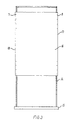
- fig. 1 shows an upright sign support 1 having a base 2 and two vertically extending profiles 3 and 4, each of which is downwardly secured to the base 2, and which are upwardly connected with a transverse profile 5 so as to form a frame structure with two parallel, vertically extending side profiles 3 and 4.
- the profiles 3 and 4 are centrally stiffened by means of a plate 6.
- the vertically extending profiles 3 and 4 are provided with a row of snap locks 7 and 8 on which sign elements 9 and 10 are mounted, said sign elements being provided with punched holes along the edges 11 and 12 of the sign elements.
- the snap locks 7 and 8 on the sign 1 are positioned such that the sign elements 10 when mounted on the snap locks 7 and 8 are caused to assume a bowed shape, thereby obtaining a desired depth effect of the plane sign element 10.
- the support 1 may be provided with sign elements 10 on both sides, and it is moreover illustrated how a source of light 13 may be located between the sign elements 10 to provide illumination of the sign elements from behind, if these should be fully or partly translucent.
- the bowed shape of the sign elements hereby ensure that the source of light is suitably spaced from the sign elements 10 so as to provide a relatively even distribution of light across the sign elements 10.
- Figs. 1 and 2 show formats of the sign elements which substantially correspond to the common A4 format, but the idea of the invention is not restricted to this and may be used in connection with any type of formats.
- Fig. 3 thus shows a sign support 14 having a base 15 on which a sign element 16 of a relatively large format is mounted. It is shown here that the holding pins do not have to extend along the entire edges 17 and 18 of the sign element 16, it being merely necessary to have a plurality of snap locks which can suitably hold the sign element 16 in a smoothly bowed shape.
- the distance between the individual snap locks may expediently have such a size as makes it possible to punch the holes in the sign element 16 shown in fig. 3 or the sign elements 10 and 11 shown in figs. 1 and 2 in a simple manner using a standard hole puncher for filing use.
- the sign element 16 is formed with punched holes at its corners, provided by means of a hole puncher for filing use which is widely used in e.g. Denmark.
- the snap locks may be formed in many different ways and may e.g. be formed as a turned or moulded rotationally symmetrical pin, as shown in fig. 2, or e.g. as a pin bent in wire or formed of sheet material. Further, the pins may be secured to the sign support in many different known ways e.g. by welding or screwing, or in that that the snap locks are formed as an integral unit with the support.
- the support may also be constructed as a lattice or frame structure established by joining standard profiles on which the snap locks 7 and 8 may be provided in the ways stated above.
- Fig. 4 shows an embodiment of a snap lock 7, said snap lock 7 being provided with outer threads 19 to be screwed into inner threads 20 in the associated holding ring 21, by means of which the snap lock may be mounted on a standard profile.
- the shown embodiments illustrate sign supports capable of standing by themselves, but the idea of the invention may equally well be applied in connection with sign supports to be hung on a wall or the like.
- the sign support may be formed such that the sign element, after mounting on the sign support, is given a bowed shape around a horizontal or vertical direction, or any given angle between these.
- the sign support may moreover be formed such that one and the same sign support allows several different orientations of the sign elements, e.g. in upright size or oblong size.
Landscapes
- Physics & Mathematics (AREA)
- General Physics & Mathematics (AREA)
- Engineering & Computer Science (AREA)
- Theoretical Computer Science (AREA)
- Road Signs Or Road Markings (AREA)
- Illuminated Signs And Luminous Advertising (AREA)
Description
Claims (8)
- A sign system comprising a support and a plurality of plane, elastically flexible sign elements, said support being provided with holding means positioned at a first distance from each other, said holding means being adapted to engage complementary holding means at the two lateral opposed edges of the sign elements, said first distance between the holding means on the support being smaller than the distance between the complementary holding means on the sign elements so that the sign elements, after mounting on the support, is caused to assume a bowed shape, wherein the holding means on the support are formed by two vertical separate rows of snap locks, said snap locks in each row being positioned at a second distance from each other, said holding means on the sign elements comprising punched holes having a dimension slightly smaller than that of the snap locks.
- A sign system according to claim 1, characterized in that the second distance between the two separate rows of snap locks is adapted to the distance between two opposed edges on a standard paper format, and that the dimension of the sign element corresponds to the same standard paper format.
- A sign system according to claim 1 or 2, characterized in that the second distances between the snap locks in each row correspond to the distance between punching means in a standard hole puncher for filing use.
- A sign system according to claims 2 and 3, characterized in that the dimension of the sign element corresponds to an A3, A4 or A5 format.
- A support for signs, said support being provided with holding means adapted to engage a plurality of plane, flexible sign elements as defined in anyone of the preceding claims, said holding means being positioned at a distance from each other and adapted to engage complementary holding means at opposed edges of the sign element, characterized in that the holding means on the support comprise two vertical separate rows of snap locks, said snap locks in each row being positioned at a distance from each other.
- A support according to any of the preceding claims, characterized in that the snap locks have an outer dimension which is slightly larger than the diameter of the punching means in a standard hole puncher.
- A support according to any of the preceding claims, characterized by being constructed as a lattice or frame structure comprising rods on which the snap locks are formed or mounted.
- A support according to claims 5-7, characterized in that the snap lock is formed with means for releasable mounting of the snap lock on the support.
Applications Claiming Priority (4)
| Application Number | Priority Date | Filing Date | Title |
|---|---|---|---|
| DK940051 | 1994-01-31 | ||
| DK9400/51 | 1994-01-31 | ||
| DK9400051U DK9400051U3 (en) | 1994-01-31 | 1994-01-31 | Sign system and stand for signs |
| PCT/DK1995/000048 WO1995020808A1 (en) | 1994-01-31 | 1995-01-31 | A sign system and a support for signs |
Publications (2)
| Publication Number | Publication Date |
|---|---|
| EP0742937A1 EP0742937A1 (en) | 1996-11-20 |
| EP0742937B1 true EP0742937B1 (en) | 1998-11-25 |
Family
ID=8154648
Family Applications (1)
| Application Number | Title | Priority Date | Filing Date |
|---|---|---|---|
| EP95908203A Expired - Lifetime EP0742937B1 (en) | 1994-01-31 | 1995-01-31 | A sign system and a support for signs |
Country Status (5)
| Country | Link |
|---|---|
| EP (1) | EP0742937B1 (en) |
| AU (1) | AU1662095A (en) |
| DE (1) | DE69506232T2 (en) |
| DK (1) | DK9400051U3 (en) |
| WO (1) | WO1995020808A1 (en) |
Families Citing this family (1)
| Publication number | Priority date | Publication date | Assignee | Title |
|---|---|---|---|---|
| GB9623465D0 (en) * | 1996-11-12 | 1997-01-08 | Melba Prod | Signs and sign assemblies |
Family Cites Families (3)
| Publication number | Priority date | Publication date | Assignee | Title |
|---|---|---|---|---|
| FR727588A (en) * | 1931-12-01 | 1932-06-20 | Removable bottom signage or advertising panel | |
| US4973212A (en) * | 1989-04-06 | 1990-11-27 | Applied Power Inc. | Snap-in fastener |
| US5212898A (en) * | 1990-04-16 | 1993-05-25 | Dinaco, Inc. | Pole sign construction |
-
1994
- 1994-01-31 DK DK9400051U patent/DK9400051U3/en active
-
1995
- 1995-01-31 EP EP95908203A patent/EP0742937B1/en not_active Expired - Lifetime
- 1995-01-31 DE DE69506232T patent/DE69506232T2/en not_active Expired - Fee Related
- 1995-01-31 WO PCT/DK1995/000048 patent/WO1995020808A1/en not_active Ceased
- 1995-01-31 AU AU16620/95A patent/AU1662095A/en not_active Abandoned
Also Published As
| Publication number | Publication date |
|---|---|
| WO1995020808A1 (en) | 1995-08-03 |
| AU1662095A (en) | 1995-08-15 |
| EP0742937A1 (en) | 1996-11-20 |
| DK9400051U3 (en) | 1994-03-11 |
| DE69506232T2 (en) | 1999-07-29 |
| DE69506232D1 (en) | 1999-01-07 |
Similar Documents
| Publication | Publication Date | Title |
|---|---|---|
| US6684591B2 (en) | Card like construction element | |
| US7926195B2 (en) | Flexible locating device | |
| US4035940A (en) | Sign construction | |
| US4729485A (en) | Fence or partition for a shelf | |
| US6760975B1 (en) | Vial holding level | |
| GB2125137A (en) | Attachment device | |
| US20160087416A1 (en) | System for mounting electrical box | |
| US20100263807A1 (en) | Freestanding modular wall | |
| US20190128015A1 (en) | Outdoor lattice system | |
| US5443238A (en) | Framed picture hanger system | |
| GB2031289A (en) | Plate assembly | |
| WO1995020808A1 (en) | A sign system and a support for signs | |
| US4972598A (en) | Sign-makers template | |
| KR200383368Y1 (en) | Frame for Artificial flower | |
| KR102044170B1 (en) | Lighting device | |
| RU2004118711A (en) | FASTENING ELEMENT, METHOD FOR BROCHURING A LOT OF SHEETS WITH A FASTENING ELEMENT AND DEVICE FOR BROCHURING A LOT OF SHEETS WITH A FASTENING ELEMENT | |
| US20050109911A1 (en) | Hanging device | |
| US11562668B2 (en) | Systems and methods for a modular signage system | |
| US876754A (en) | Street-sign. | |
| JPH1033327A (en) | Upward set shelf | |
| ES2042176T3 (en) | SUPPORT GRILLE FOR A LOWER COVER. | |
| EP1347430B1 (en) | Clamp for gripping a cable | |
| KR200440220Y1 (en) | Drawing paper | |
| JP3018875U (en) | Display sheet posting tool | |
| EP1244087B1 (en) | Advertising standard for mounting and stretching of posters |
Legal Events
| Date | Code | Title | Description |
|---|---|---|---|
| PUAI | Public reference made under article 153(3) epc to a published international application that has entered the european phase |
Free format text: ORIGINAL CODE: 0009012 |
|
| 17P | Request for examination filed |
Effective date: 19960828 |
|
| AK | Designated contracting states |
Kind code of ref document: A1 Designated state(s): DE FR GB |
|
| GRAG | Despatch of communication of intention to grant |
Free format text: ORIGINAL CODE: EPIDOS AGRA |
|
| 17Q | First examination report despatched |
Effective date: 19971230 |
|
| GRAG | Despatch of communication of intention to grant |
Free format text: ORIGINAL CODE: EPIDOS AGRA |
|
| GRAH | Despatch of communication of intention to grant a patent |
Free format text: ORIGINAL CODE: EPIDOS IGRA |
|
| GRAH | Despatch of communication of intention to grant a patent |
Free format text: ORIGINAL CODE: EPIDOS IGRA |
|
| GRAA | (expected) grant |
Free format text: ORIGINAL CODE: 0009210 |
|
| AK | Designated contracting states |
Kind code of ref document: B1 Designated state(s): DE FR GB |
|
| REF | Corresponds to: |
Ref document number: 69506232 Country of ref document: DE Date of ref document: 19990107 |
|
| ET | Fr: translation filed | ||
| PLBE | No opposition filed within time limit |
Free format text: ORIGINAL CODE: 0009261 |
|
| STAA | Information on the status of an ep patent application or granted ep patent |
Free format text: STATUS: NO OPPOSITION FILED WITHIN TIME LIMIT |
|
| 26N | No opposition filed | ||
| PGFP | Annual fee paid to national office [announced via postgrant information from national office to epo] |
Ref country code: DE Payment date: 20011227 Year of fee payment: 8 |
|
| PGFP | Annual fee paid to national office [announced via postgrant information from national office to epo] |
Ref country code: FR Payment date: 20011228 Year of fee payment: 8 |
|
| PGFP | Annual fee paid to national office [announced via postgrant information from national office to epo] |
Ref country code: GB Payment date: 20011231 Year of fee payment: 8 |
|
| REG | Reference to a national code |
Ref country code: GB Ref legal event code: IF02 |
|
| PG25 | Lapsed in a contracting state [announced via postgrant information from national office to epo] |
Ref country code: GB Free format text: LAPSE BECAUSE OF NON-PAYMENT OF DUE FEES Effective date: 20030131 |
|
| PG25 | Lapsed in a contracting state [announced via postgrant information from national office to epo] |
Ref country code: DE Free format text: LAPSE BECAUSE OF NON-PAYMENT OF DUE FEES Effective date: 20030801 |
|
| GBPC | Gb: european patent ceased through non-payment of renewal fee | ||
| PG25 | Lapsed in a contracting state [announced via postgrant information from national office to epo] |
Ref country code: FR Free format text: LAPSE BECAUSE OF NON-PAYMENT OF DUE FEES Effective date: 20030930 |
|
| REG | Reference to a national code |
Ref country code: FR Ref legal event code: ST |