EP0742630B1 - Procédé de commande de mouvement d'un ouvrant - Google Patents
Procédé de commande de mouvement d'un ouvrant Download PDFInfo
- Publication number
- EP0742630B1 EP0742630B1 EP96400969A EP96400969A EP0742630B1 EP 0742630 B1 EP0742630 B1 EP 0742630B1 EP 96400969 A EP96400969 A EP 96400969A EP 96400969 A EP96400969 A EP 96400969A EP 0742630 B1 EP0742630 B1 EP 0742630B1
- Authority
- EP
- European Patent Office
- Prior art keywords
- abovementioned
- safety threshold
- closure
- safety
- movement
- Prior art date
- Legal status (The legal status is an assumption and is not a legal conclusion. Google has not performed a legal analysis and makes no representation as to the accuracy of the status listed.)
- Expired - Lifetime
Links
Images


Classifications
-
- H—ELECTRICITY
- H02—GENERATION; CONVERSION OR DISTRIBUTION OF ELECTRIC POWER
- H02H—EMERGENCY PROTECTIVE CIRCUIT ARRANGEMENTS
- H02H7/00—Emergency protective circuit arrangements specially adapted for specific types of electric machines or apparatus or for sectionalised protection of cable or line systems, and effecting automatic switching in the event of an undesired change from normal working conditions
- H02H7/08—Emergency protective circuit arrangements specially adapted for specific types of electric machines or apparatus or for sectionalised protection of cable or line systems, and effecting automatic switching in the event of an undesired change from normal working conditions for dynamo-electric motors
- H02H7/085—Emergency protective circuit arrangements specially adapted for specific types of electric machines or apparatus or for sectionalised protection of cable or line systems, and effecting automatic switching in the event of an undesired change from normal working conditions for dynamo-electric motors against excessive load
- H02H7/0851—Emergency protective circuit arrangements specially adapted for specific types of electric machines or apparatus or for sectionalised protection of cable or line systems, and effecting automatic switching in the event of an undesired change from normal working conditions for dynamo-electric motors against excessive load for motors actuating a movable member between two end positions, e.g. detecting an end position or obstruction by overload signal
-
- H—ELECTRICITY
- H02—GENERATION; CONVERSION OR DISTRIBUTION OF ELECTRIC POWER
- H02H—EMERGENCY PROTECTIVE CIRCUIT ARRANGEMENTS
- H02H3/00—Emergency protective circuit arrangements for automatic disconnection directly responsive to an undesired change from normal electric working condition with or without subsequent reconnection ; integrated protection
- H02H3/006—Calibration or setting of parameters
Definitions
- the present invention relates to a control method movement of an opening leaf such as a door, a barrier, a shutter, or others, in particular with horizontal or vertical, rotary movements, sliding, tilting or rolling, or combined.
- the above safety threshold is adjustable by the user or the installer but requires intervention on the automation.
- the user or the installer sets this threshold to one higher level so that the automation can operate again and execute the movements of the opening. It follows that, in order not to intervene in the setting of the aforementioned safety threshold, the user or the installer tend to set this security threshold at a high level so that it no longer really fulfills its security role and that during its movement the sash can cause injuries especially children or animals.
- An object of the present invention is to provide a method of controlling the movement of an opening allowing safely cross an obstacle that the user wishes could meet the opening during its movement, that this obstacle either momentary or for example snow or mud or that this obstacle is persistent, due for example to aging or wear training bodies.
- Another object of the present invention is to provide a method of controlling a movement capable of generating a safety adapted in particular to the mechanical characteristics of the opening and its drive bodies.
- Another object of the present invention is to provide a method of controlling the movement of a sash capable of holding account of the conditions of use, in particular namely the presence a total obstacle to the movement of the opening producing a shock or the presence of a slower obstacle such as wind or mechanical wear of the drive members, thus allowing to obtain a sensitivity adapted to events.
- the method of controlling the movement of an opening such as that a door, a barrier, a shutter, or the like, driven by a motor member over at least part of the travel of said opening, in which the drive unit can be started or stopped by a command to on-off control, according to the invention consists in setting a threshold of initial safety equal to a determined value of a basic data representative of the effort provided by said motor body to drive opening it, to measure this basic data during the movements of the opening, to compare this measured value of this basic data audit initial safety threshold and to cause a safety shutdown of said drive member in case the measured value of this basic data reaches this initial security threshold.
- control method consists, following at the aforementioned safety stop, by a new command order, to be inhibited said initial security threshold, to set a new security threshold representative of a higher effort and to cause restarting of said motor organ, and that it consists in causing a safety stop of said drive member in case the measured value of said datum base reaches said new safety threshold.
- the method can advantageously consist, in case the measured value of the basic data reaches at new said initial safety threshold during at least the movement depending on the opening, to replace the initial security threshold with the new security threshold mentioned above.
- the method can advantageously consist, after a predetermined period or a number predetermined opening movement following the safety stop aforementioned, to replace the aforementioned new security threshold with said initial safety in case the measured value of the basic data does not reach said new safety threshold after this time or this number.
- the method can advantageously consist in fixing at least a representative maximum safety threshold maximum effort and to cause a safety stop of said drive member in case the measured value of the aforementioned basic data reaches this maximum security threshold.
- the aforementioned new order order may be identical to said run command command.
- the aforementioned new order order may consist of a particular order.
- the aforementioned new order order may consist in maintaining said order to run at less for a preset time.
- the new order order could be said run command, provided that this command run command is activated at maximum within a specified time compared to the time of the aforementioned safety stop.
- the method can advantageously consist of setting several initial safety thresholds distributed over the length of the opening stroke, to which are respectively associated with new security thresholds.
- the method can advantageously consist, during each movement of the opening, to divide minus part of the corresponding opening and / or closing time to the full stroke of the sash in time slices or at least one part of this race in slices of movement, to be done during of each opening and / or closing movement of the opening, in each of the above-mentioned sections, the measurement of representative data of the effort provided by the motor, to calculate differences consisting of the difference between a base value which is a function of at least the measured value of the above-mentioned data in each of the sections above and a base value which is a function of at least the measured value of the aforementioned data in the previous section, and consist (1), during a learning movement, to be fixed in each of the sections above an initial safety threshold depending on the aforementioned difference associated with at least one section, and (2) during each of the movements of the opening after said learning movement, successively compare the aforementioned difference associated with each slice to the associated initial safety threshold, and to cause said stop motor organ if this difference reaches this initial safety
- the method can advantageously consist in dividing at least part of the opening time and / or closure corresponding to the total travel of the opening in zones of time or at least part of this race in displacement zones, and to set a common initial safety threshold in the aforementioned tranches of each of these areas.
- the above-mentioned basic value can be function of the average of at least two successive measured data.
- the method can advantageously consist, during the movements of the opening to be fixed, each time that the aforementioned difference goes through zero, a safety threshold complementary function of the value of the data measured in this wafer, to cause a safety stop of said motor member during subsequent movement of the sash in case a measured value of the The above mentioned data reaches this additional safety threshold.
- the method can advantageously consist in modifying the duration of each of the slices and / or zones of aforementioned times as a function of the energy delivered by the energy source operating said motor member.
- a barrier generally identified by the reference 1 which has an opening or wing 2 with pivoting movement articulated on a vertical axis 3 connected to a post 4.
- the opening 2 is connected to the vertical axis 5 of a motor electric drive 6, associated with a mechanical reducer, by a articulated arm with two levers 7 and 8, the amplitude of the rotational movement of the drive axis 5 and the arrangement of the levers 7 and 8 being such that the opening 2 can occupy two extreme positions located by example at around 90 °, these two extreme positions being delimited by stops 7a and 8a carried by the levers 7 and 8.
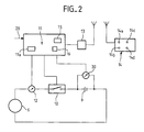
- the electric motor 6 can be powered by an energy source electric 9, for example by a battery through a switch electric 10 on / off.
- An intensity detector 12 makes it possible to measure the intensity of the electric current supplied to the motor electric 6.
- the automation includes an electronic processing and management circuit 11 which receives control commands from a detection and decoding circuit of signals 13 emitted by a remote control 14.
- a remote control 14 receives control commands from a detection and decoding circuit of signals 13 emitted by a remote control 14.
- the connection between the remote control 14 and the detection circuit 13 is effected by radio signals.
- Circuit 11 includes a register memory 15 in which are stored an initial safety threshold S1 representative of a determined value of the intensity of the electric current passing through the motor 6 and consequently a determined value of the effort likely to be provided by the latter to drive the opening 2, as well that a new security threshold S2 corresponding to a value determined of the intensity greater than the value of the intensity fixing the threshold S1, and consequently corresponding to a higher effort likely to be provided by the electric motor 6 to drive opening it 2.
- the circuit 11 also includes a memory 16 in which is stored a maximum security threshold SM corresponding to an intensity value of the electric current likely to pass through the electric motor 6 greater than the value associated with said new threshold security S2.
- the electronic circuit also includes, reference 11a, a microprocessor associated with peripheral circuits.
- a run command M1 reference 17, transmitted by the user using the remote control 14 in pressing for example a start button 14a is received by the circuit 11 which causes the switch 10 to close.
- the motor electric 6 is powered and causes movement, reference 18, opening of the opening 2, the opening immobilizing for this purpose race.
- the user can transmit a voluntary stop order, reference 21, for example by pressing a button 14b on the remote control 14 which allows opening of switch 10 and consequently stopping the supply of electric motor 6, the opening 2 coming to a stop at a chosen place in its race.
- the reverse closing movement of sash 2 can be obtained by reversing the current flowing through electric motor 6, the user transmitting a run command in consequence by acting for example on a button 14c of the remote control 14.
- the value of the intensity of the electric current passing through the motor electric 6 is measured by the intensity detector, reference 12, and this value is compared, reference 22, to the initial safety threshold S1 stored in register memory 15.
- this new M2 operating order causes the closure of the switch 10 and consequently again the supply of the electric motor 6 and the opening sash 2.
- the measured intensity, reference 12 of the electric current passing through the electric motor 6 is compared, reference 22, no longer at the threshold of initial security S1 but at the new security threshold S2 stored in the register memory 15.
- this measured value, reference 12 does not reach this new safety threshold S2, movement of the sash 2 occurs normally. If, on the contrary, this measured value, reference 12, reaches this new safety threshold S2, a safety stop order AS, reference 20, ensures the opening of the switch 10 and causes a stop opening 2 safety by cutting the motor supply electric 6.
- the electronic circuit 11 makes it possible to compare gradually the effort provided by the electric motor 6 at the threshold of security S1 then at the security threshold S2 in case the threshold S1 would have been reached or crossed.
- the initial safety threshold S1 can be restored at the end of the race, reference 19, from the movement during which AS safety shutdown has occurred.
- the initial safety threshold can be restored after a specified number of movements in the same direction of opening 2, by counting, reference 26, for race, reference 19, of the opening 2 or after a fixed period, reference 27, insofar as the new safety threshold S2 is not reached during these movements or during this duration.
- the new security threshold S2 can be maintained permanently and during subsequent movements opening the measured value, reference 12, of the current intensity electric through electric motor 6 will be compared to this new security threshold S2.
- the security threshold S2 becomes equivalent to the initial safety threshold S1 and a new threshold of safety S3 can be recalculated and equal for example to 1.20 times this new initial safety threshold S2. Consequently, by recursion, it it is possible to provide several security thresholds and to go from one to the other as previously described both in the increasing direction and in the decreasing sense.
- the new M2 order may not be differentiated from the order of normal step M1, reference 17, and simply be constituted by this last. It could be in a variant constituted by this order of normal operation M1, reference 17, provided that it is maintained for a determined period of time by holding the pressed position down control button 14a on the remote control 14. In another variant, the new M2 order could be the order normal M1, provided that this normal M1 run command is activated at most within a specified time from the time of the judgment aforementioned security AS.
- this end of stroke detection can in a variant be delivered to the electronic circuit 11 by sensors of opening limit switches 2.
- the end of stroke detection, reference 19, of the opening 2 can be obtained through the effect of the stops 7a or 8a which when reached cause a sharp increase in the measured value, reference 12, of the intensity of the electric current passing through the electric motor 6, in combination with the position of the sash 2, reference 18, determined by the sensors position or by an expected duration of the movement during the opening 2.
- the detection limit switch thus achieved by the expected duration of the movement of opening 2 is not considered to exceed the thresholds of safety S1, S2, SM and does not influence the effects of the comparison of the value of the intensity of the electric current passing through the motor electric 6, a particular limit detection limit, preference different from the thresholds S1, S2, SM which may be provided for this purpose and saved in a memory.
- the stroke of the leaf 2 can be divided into several parts, either determined by portions or sectors of the opening 2 stroke delimited by sensors positions, either by opening times of the opening 2 in these parts, for which security thresholds would be provided respectively different initials S1 with which new thresholds would be associated different S2 security.
- security thresholds would be provided respectively different initials S1 with which new thresholds would be associated different S2 security.
- the initial safety threshold S1 and the new security threshold S2 can be prefixed or, in another variant, may result from a learning operation that the circuit electronics 11 can perform as follows, on an order , reference 28, delivered to circuit 11 preferably by a other than the remote control 14, for example by a button directly associated with circuit 11.
- the electronic circuit 11 is adapted to divide the opening 2, during each of its movements, in Tn time slices, taking into account the duration of each movement, or in slices Tn of determined angular displacements for example by a sensor.
- the electronic circuit 11 is suitable for carrying out, during each opening movement and the opening 2, the reading of the value of the intensity of the current passing through the motor 6 which the intensity sensor 12 delivers to it.
- the electronic circuit 11 is adapted to calculate differences Dn consisting of the difference between the measured value In of the intensity in each, Tn, of the above-mentioned sections and the measured value In-1 of the intensity in the anterior section Tn-1.
- the user orders, for example thanks to the button associated with the input 28 of the electronic circuit 11, a movement of the door 2 during which the electronic circuit 11 is learning.
- This learning consists in fixing in each of the aforementioned slices Tn an initial safety threshold Sn1 depending on the aforementioned difference Dn associated with the slice Tn in question.
- the safety thresholds Sn1 can be equal to 1.20 times the value of the differences Dn.
- These initial safety thresholds Sn1 are recorded in the memory-register 15.
- the circuit electronics 11 successively compares the aforementioned difference Dn associated with each slice Tn with the associated initial safety threshold Sn1 and works, in each Tn section, as described above for if necessary cause the AS safety shutdown of the sash 2 and the passage of the initial safety threshold Sn1 to the new safety threshold Sn2 with resumption of movement.
- the electronic circuit 11 is suitable for dividing the opening time and the closing time corresponding to the total travel of the opening 2 in zones Zm of time or this race in zones Zm of displacement, and to fix a threshold of initial safety Sm1 common in the aforementioned sections of each of these Zm zones.
- the initial safety thresholds Sm1 can be equal to 1.20 times the value of the highest difference Dn in the slice Tn of each of the zones Zm.
- Sm2 safety thresholds are then determined according to these initial safety thresholds Sm2 as previously described.
- the electronic circuit 11 can be suitable for calculating the above-mentioned differences Dn from averages of values of the intensity In, supplied by the sensor 12, taken in two or several successive Tn slices.
- the electronic circuit 11 is also suitable for being sensitive to a safety threshold which is stored in the memory-register 15. For this, during the movements of the opening 2, the electronic circuit 11 fixes, each time the aforementioned difference Dn goes through zero, a threshold of additional safety Sc equal for example to 1.20 times the value of the the intensity In measured in the slice Tn in which this zero crossing.
- the electronic circuit 11 causes a stop of safety AS of the electric motor 6 during movement of the leaf 2 following this section in case a measured value of the intensity delivered by sensor 12 reaches this safety threshold complementary Sc.
- the total duration of the opening 2 depends of the energy available in the battery 9. It is therefore desirable that the electronic circuit 11 is adapted to modify the duration of each time slices Tn and time zones Zm mentioned above in function of the energy delivered by the battery 9 operating the said electric motor 6. For this, the electronic circuit 11 receives the value of the voltage across the battery 9 by a voltage sensor 30.
Landscapes
- Power-Operated Mechanisms For Wings (AREA)
- Control And Other Processes For Unpacking Of Materials (AREA)
- Operating, Guiding And Securing Of Roll- Type Closing Members (AREA)
- Ultra Sonic Daignosis Equipment (AREA)
- Transition And Organic Metals Composition Catalysts For Addition Polymerization (AREA)
- Farming Of Fish And Shellfish (AREA)
- Automatic Analysis And Handling Materials Therefor (AREA)
- Window Of Vehicle (AREA)
- Vehicle Body Suspensions (AREA)
- Paper (AREA)
- User Interface Of Digital Computer (AREA)
- Control Of Electric Motors In General (AREA)
Applications Claiming Priority (2)
| Application Number | Priority Date | Filing Date | Title |
|---|---|---|---|
| FR9505566A FR2734018B1 (fr) | 1995-05-11 | 1995-05-11 | Procede de commande de mouvement d'un ouvrant |
| FR9505566 | 1995-05-11 |
Publications (2)
| Publication Number | Publication Date |
|---|---|
| EP0742630A1 EP0742630A1 (fr) | 1996-11-13 |
| EP0742630B1 true EP0742630B1 (fr) | 2001-10-24 |
Family
ID=9478861
Family Applications (1)
| Application Number | Title | Priority Date | Filing Date |
|---|---|---|---|
| EP96400969A Expired - Lifetime EP0742630B1 (fr) | 1995-05-11 | 1996-05-07 | Procédé de commande de mouvement d'un ouvrant |
Country Status (6)
| Country | Link |
|---|---|
| EP (1) | EP0742630B1 (da) |
| AT (1) | ATE207666T1 (da) |
| DE (1) | DE69616143T2 (da) |
| DK (1) | DK0742630T3 (da) |
| ES (1) | ES2161990T3 (da) |
| FR (1) | FR2734018B1 (da) |
Families Citing this family (1)
| Publication number | Priority date | Publication date | Assignee | Title |
|---|---|---|---|---|
| FR2776136B1 (fr) * | 1998-03-13 | 2000-06-02 | Valeo Systemes Dessuyage | Bloc moteur electrique, notamment pour vehicule automobile, integrant une electronique de commande |
Family Cites Families (2)
| Publication number | Priority date | Publication date | Assignee | Title |
|---|---|---|---|---|
| GB2147432B (en) * | 1983-09-28 | 1987-01-14 | Aisin Seiki | Controlling movement |
| GB2269282A (en) * | 1992-07-29 | 1994-02-02 | Gen Electric Co Plc | Controlling movement by electric motor using current monitoring |
-
1995
- 1995-05-11 FR FR9505566A patent/FR2734018B1/fr not_active Expired - Lifetime
-
1996
- 1996-05-07 EP EP96400969A patent/EP0742630B1/fr not_active Expired - Lifetime
- 1996-05-07 ES ES96400969T patent/ES2161990T3/es not_active Expired - Lifetime
- 1996-05-07 DE DE69616143T patent/DE69616143T2/de not_active Expired - Lifetime
- 1996-05-07 DK DK96400969T patent/DK0742630T3/da active
- 1996-05-07 AT AT96400969T patent/ATE207666T1/de not_active IP Right Cessation
Also Published As
| Publication number | Publication date |
|---|---|
| ES2161990T3 (es) | 2001-12-16 |
| DE69616143D1 (de) | 2001-11-29 |
| EP0742630A1 (fr) | 1996-11-13 |
| FR2734018B1 (fr) | 1997-07-25 |
| DK0742630T3 (da) | 2002-02-18 |
| FR2734018A1 (fr) | 1996-11-15 |
| DE69616143T2 (de) | 2002-03-14 |
| ATE207666T1 (de) | 2001-11-15 |
Similar Documents
| Publication | Publication Date | Title |
|---|---|---|
| EP0550426B1 (fr) | Dispositif de contrÔle thermique d'un moteur électrique embarqué à bord d'un véhicule, notamment pour un système de direction assistée | |
| CN1891965B (zh) | 车窗开闭控制装置 | |
| FR2944116A1 (fr) | Dispositif de commande en deplacement d'un element selon deux sens opposes. | |
| EP0521818A1 (fr) | Installation de commande du niveau d'éclairement d'un local | |
| EP0439422A1 (fr) | Dispositif de sécurité pour volet roulant motorisé | |
| FR2754117A1 (fr) | Dispositif de commande pour moteur asynchrone de store ou volet roulant | |
| EP1508844B1 (fr) | Procédé d' initialisation d' un volet roulant motorisé | |
| FR2894094A1 (fr) | Detection anti-pincement operant sur le principe de la comparaison du coefficient d'utilisation d'une regulation par modulation de largeur d'impulsions. | |
| EP1659252A1 (fr) | Procédé de fonctionnement d'un volet roulant motorisé | |
| EP0742630B1 (fr) | Procédé de commande de mouvement d'un ouvrant | |
| FR2915817A1 (fr) | Procede de commande d'un element deplacable dans un vehicule automobile, et dispositif d'actionnement de deplacement | |
| WO2009050664A2 (fr) | Procede d'analyse du fonctionnement d'un actionneur electromecanique pour la manoeuvre motorisee d'un ecran et actionneur pour sa mise en oeuvre | |
| FR2837522A1 (fr) | Procede de determination d'une position intermediaire ajouree d'un volet roulant | |
| EP0744679B1 (fr) | Procédé de commande électronique d'ouverture et/ou de fermeture d'une porte et dispositif pour sa mise en oeuvre | |
| FR2599072A1 (fr) | Dispositif de reglage reagissant a au moins une influence de l'environnement pour le couvercle dispose de facon rabattable d'une lucarne de toit, en particulier pour une coupole transparente | |
| FR2626118A1 (fr) | Dispositif de controle d'un moteur a courant continu destine notamment a commande d'ouvrants sur des vehicules automobiles | |
| FR2771521A1 (fr) | Dispositif de commande d'un moyen de protection solaire motorise | |
| FR2696884A1 (fr) | Procédé et dispositif de commande d'un moteur électrique, notamment pour lève-vitre d'automobile. | |
| FR2657646A1 (fr) | Dispositif de securite pour volet roulant motorise. | |
| EP1804709B1 (fr) | Appareil de traitement dentaire a lime rotative | |
| EP2015156B1 (fr) | Procédé de fonctionnement d'une installation domotique et installation domotique pour sa mise en oeuvre | |
| EP0600798B1 (fr) | Dispositif de correction automatique de l'orientation des projecteurs d'un véhicle automobile lors des variations d'assiette du véhicule | |
| EP0618341B1 (fr) | Dispositif de protection d'une ouverture telle que par exemple un volet roulant | |
| FR2902582A1 (fr) | Dispositif de commande d'un moteur a deux sens de rotation | |
| FR2822184A1 (fr) | Systeme de commande d'entrainement automatique d'une porte, notamment d'une porte interieure pour vehicule ferroviaire de transport de passagers |
Legal Events
| Date | Code | Title | Description |
|---|---|---|---|
| PUAI | Public reference made under article 153(3) epc to a published international application that has entered the european phase |
Free format text: ORIGINAL CODE: 0009012 |
|
| AK | Designated contracting states |
Kind code of ref document: A1 Designated state(s): AT BE CH DE DK ES GB IT LI NL SE |
|
| 17P | Request for examination filed |
Effective date: 19970401 |
|
| 17Q | First examination report despatched |
Effective date: 19991025 |
|
| GRAG | Despatch of communication of intention to grant |
Free format text: ORIGINAL CODE: EPIDOS AGRA |
|
| GRAG | Despatch of communication of intention to grant |
Free format text: ORIGINAL CODE: EPIDOS AGRA |
|
| GRAH | Despatch of communication of intention to grant a patent |
Free format text: ORIGINAL CODE: EPIDOS IGRA |
|
| GRAH | Despatch of communication of intention to grant a patent |
Free format text: ORIGINAL CODE: EPIDOS IGRA |
|
| GRAA | (expected) grant |
Free format text: ORIGINAL CODE: 0009210 |
|
| ITF | It: translation for a ep patent filed | ||
| AK | Designated contracting states |
Kind code of ref document: B1 Designated state(s): AT BE CH DE DK ES GB IT LI NL SE |
|
| REF | Corresponds to: |
Ref document number: 207666 Country of ref document: AT Date of ref document: 20011115 Kind code of ref document: T |
|
| REG | Reference to a national code |
Ref country code: CH Ref legal event code: EP |
|
| GBT | Gb: translation of ep patent filed (gb section 77(6)(a)/1977) |
Effective date: 20011024 |
|
| REF | Corresponds to: |
Ref document number: 69616143 Country of ref document: DE Date of ref document: 20011129 |
|
| REG | Reference to a national code |
Ref country code: ES Ref legal event code: FG2A Ref document number: 2161990 Country of ref document: ES Kind code of ref document: T3 |
|
| REG | Reference to a national code |
Ref country code: GB Ref legal event code: IF02 |
|
| REG | Reference to a national code |
Ref country code: DK Ref legal event code: T3 |
|
| PGFP | Annual fee paid to national office [announced via postgrant information from national office to epo] |
Ref country code: DK Payment date: 20020506 Year of fee payment: 7 |
|
| PGFP | Annual fee paid to national office [announced via postgrant information from national office to epo] |
Ref country code: SE Payment date: 20020517 Year of fee payment: 7 |
|
| PGFP | Annual fee paid to national office [announced via postgrant information from national office to epo] |
Ref country code: BE Payment date: 20020524 Year of fee payment: 7 Ref country code: AT Payment date: 20020524 Year of fee payment: 7 |
|
| PGFP | Annual fee paid to national office [announced via postgrant information from national office to epo] |
Ref country code: NL Payment date: 20020531 Year of fee payment: 7 |
|
| REG | Reference to a national code |
Ref country code: CH Ref legal event code: NV Representative=s name: KIRKER & CIE SA |
|
| PGFP | Annual fee paid to national office [announced via postgrant information from national office to epo] |
Ref country code: CH Payment date: 20020730 Year of fee payment: 7 |
|
| PLBE | No opposition filed within time limit |
Free format text: ORIGINAL CODE: 0009261 |
|
| STAA | Information on the status of an ep patent application or granted ep patent |
Free format text: STATUS: NO OPPOSITION FILED WITHIN TIME LIMIT |
|
| 26N | No opposition filed | ||
| PG25 | Lapsed in a contracting state [announced via postgrant information from national office to epo] |
Ref country code: AT Free format text: LAPSE BECAUSE OF NON-PAYMENT OF DUE FEES Effective date: 20030507 |
|
| PG25 | Lapsed in a contracting state [announced via postgrant information from national office to epo] |
Ref country code: SE Free format text: LAPSE BECAUSE OF NON-PAYMENT OF DUE FEES Effective date: 20030508 |
|
| PG25 | Lapsed in a contracting state [announced via postgrant information from national office to epo] |
Ref country code: LI Free format text: LAPSE BECAUSE OF NON-PAYMENT OF DUE FEES Effective date: 20030531 Ref country code: CH Free format text: LAPSE BECAUSE OF NON-PAYMENT OF DUE FEES Effective date: 20030531 Ref country code: BE Free format text: LAPSE BECAUSE OF NON-PAYMENT OF DUE FEES Effective date: 20030531 |
|
| BERE | Be: lapsed |
Owner name: *ATRAL Effective date: 20030531 |
|
| PG25 | Lapsed in a contracting state [announced via postgrant information from national office to epo] |
Ref country code: NL Free format text: LAPSE BECAUSE OF NON-PAYMENT OF DUE FEES Effective date: 20031201 Ref country code: DK Free format text: LAPSE BECAUSE OF NON-PAYMENT OF DUE FEES Effective date: 20031201 |
|
| REG | Reference to a national code |
Ref country code: DK Ref legal event code: EBP |
|
| EUG | Se: european patent has lapsed | ||
| REG | Reference to a national code |
Ref country code: CH Ref legal event code: PL |
|
| NLV4 | Nl: lapsed or anulled due to non-payment of the annual fee |
Effective date: 20031201 |
|
| REG | Reference to a national code |
Ref country code: DE Ref legal event code: R082 Ref document number: 69616143 Country of ref document: DE Representative=s name: MEISSNER BOLTE PATENTANWAELTE RECHTSANWAELTE P, DE Ref country code: DE Ref legal event code: R082 Ref document number: 69616143 Country of ref document: DE Representative=s name: MEISSNER, BOLTE & PARTNER GBR, DE |
|
| REG | Reference to a national code |
Ref country code: DE Ref legal event code: R082 Ref document number: 69616143 Country of ref document: DE Representative=s name: MEISSNER, BOLTE & PARTNER GBR, DE |
|
| PGFP | Annual fee paid to national office [announced via postgrant information from national office to epo] |
Ref country code: GB Payment date: 20150529 Year of fee payment: 20 Ref country code: ES Payment date: 20150508 Year of fee payment: 20 |
|
| PGFP | Annual fee paid to national office [announced via postgrant information from national office to epo] |
Ref country code: IT Payment date: 20150511 Year of fee payment: 20 |
|
| PGFP | Annual fee paid to national office [announced via postgrant information from national office to epo] |
Ref country code: DE Payment date: 20150730 Year of fee payment: 20 |
|
| REG | Reference to a national code |
Ref country code: DE Ref legal event code: R071 Ref document number: 69616143 Country of ref document: DE |
|
| REG | Reference to a national code |
Ref country code: GB Ref legal event code: PE20 Expiry date: 20160506 |
|
| PG25 | Lapsed in a contracting state [announced via postgrant information from national office to epo] |
Ref country code: GB Free format text: LAPSE BECAUSE OF EXPIRATION OF PROTECTION Effective date: 20160506 |
|
| REG | Reference to a national code |
Ref country code: ES Ref legal event code: FD2A Effective date: 20160826 |
|
| PG25 | Lapsed in a contracting state [announced via postgrant information from national office to epo] |
Ref country code: ES Free format text: LAPSE BECAUSE OF EXPIRATION OF PROTECTION Effective date: 20160508 |