EP0741630B1 - Improvements in or relating to grinding - Google Patents
Improvements in or relating to grinding Download PDFInfo
- Publication number
- EP0741630B1 EP0741630B1 EP95906426A EP95906426A EP0741630B1 EP 0741630 B1 EP0741630 B1 EP 0741630B1 EP 95906426 A EP95906426 A EP 95906426A EP 95906426 A EP95906426 A EP 95906426A EP 0741630 B1 EP0741630 B1 EP 0741630B1
- Authority
- EP
- European Patent Office
- Prior art keywords
- cam
- grinding
- grinding wheel
- camshaft
- workpiece
- Prior art date
- Legal status (The legal status is an assumption and is not a legal conclusion. Google has not performed a legal analysis and makes no representation as to the accuracy of the status listed.)
- Expired - Lifetime
Links
Images


Classifications
-
- B—PERFORMING OPERATIONS; TRANSPORTING
- B24—GRINDING; POLISHING
- B24B—MACHINES, DEVICES, OR PROCESSES FOR GRINDING OR POLISHING; DRESSING OR CONDITIONING OF ABRADING SURFACES; FEEDING OF GRINDING, POLISHING, OR LAPPING AGENTS
- B24B19/00—Single-purpose machines or devices for particular grinding operations not covered by any other main group
- B24B19/08—Single-purpose machines or devices for particular grinding operations not covered by any other main group for grinding non-circular cross-sections, e.g. shafts of elliptical or polygonal cross-section
- B24B19/12—Single-purpose machines or devices for particular grinding operations not covered by any other main group for grinding non-circular cross-sections, e.g. shafts of elliptical or polygonal cross-section for grinding cams or camshafts
- B24B19/125—Single-purpose machines or devices for particular grinding operations not covered by any other main group for grinding non-circular cross-sections, e.g. shafts of elliptical or polygonal cross-section for grinding cams or camshafts electrically controlled, e.g. numerically controlled
Definitions
- This invention relates to a method of grinding, and more especially to the rough grinding of a workpiece having one or more lobes, such as a camshaft cam, and also to a grinding machine for performing such method.
- Rough grinding of fixed workpieces is conventionally carried out by a progressive infeed/outfeed movement of the grinding wheel of increasing depth, so that parts of the workpiece requiring maximum grinding are only worked upon at the end of the progression of feed movements.
- the conventional method has the disadvantage that a retraction mark is left on the workpiece at the point where the wheel and workpiece finally separate, especially since the workpiece profile at the point of retraction will be a point of maximum depth of grinding.
- EP-A-0085225 there is disclosed a machine for rough grinding a cam in which the grinding wheel first contacts the workpiece cam at the centre of the cam nose, ie at the peak of the cam lobe, and removes material from the cam during two rotations thereof.
- the amount removed during the first rotation is greater than that at the second rotation, the cam being rotated in accordance with a selected velocity curve, including acceleration/deceleration segments.
- a method of rough grinding a cam within a maximum of two rotations of the cam workpiece relative to a grinding wheel wherein rotation of the cam and operation of the cam/grinding wheel infeed/outfeed are synchronised to cause the grinding wheel first to contact and engage the workpiece and, as infeed continues, to remove material so that the radius of the peak of the cam lobe is attained at the intended position of the peak as it becomes aligned with the grinding wheel with rotation of the workpiece, and thereafter, by continued rotation of the workpiece and infeed/outfeed operation, remove material from the workpiece so as to attain the required contour of the remainder of the cam, and finally breaking contact with the ground face of the cam, characterised in that the first contact between the workpiece and the grinding wheel is ahead of the intended position of the peak of the cam lobe therearound, and in that finally contact with the ground face is broken, at or after the peak of the lobe has become aligned with the grinding wheel for a second time but before the third such alignment.
- Finish grinding may be carried out with the same or a different grinding wheel, or by means of a belt grinder.
- Surface hardening may be interposed between rough grinding and finish grinding.
- a grinding machine for carrying out the above defined method, equipped with control means for synchronising workpiece rotation and infeed/outfeed movement of the grinding wheel and cam.
- This machine is defined in claim 5.
- the cam for example, may be a cam on a camshaft, which typically requires to be ground with a plurality of lobed cams.
- camshaft indexing along its axis from one cam workpiece to the next is synchronised relative to the infeed/outfeed movements of the grinding wheel and to the camshaft, so that the next cam workpiece is engaged by the grinding wheel.
- a camshaft grinding machine comprising a bed, means for supporting and rotating a camshaft to be ground relative to a grinding wheel, infeed/outfeed drive means for moving the cam and grinding wheel relative to each other, first position sensing means for determining the distance between the longitudinal axis of the camshaft and the nearest point thereto on the surface of the grinding wheel, second position sensing means for determining the angular position of the rotating camshaft, control means responsive to signals from the two position sensing means to control the drive means, means containing radius data relative to rotational shaft position and means for utilising the radius/position data to control the infeed/outfeed drive means to remove more or less material from the camshaft to attain the desired profile around the camshaft in not more than two rations of the camshaft, characterised in that the drive means are controlled such that the wheel and the camshaft are caused to engage just prior to when the region of maximum radius of the cam lobe to be ground becomes aligned with a plane containing the axis
- the method in accordance with the invention has the advantage that rough grinding can be performed much more quickly, specifically in little more than one turn of the cam workpiece. Moreover, because the grinding wheel separates from the cam at the nose position, the presence of a retraction mark can be substantially avoided. Thus, if desired, the grinding wheel can dwell for a short period at the depth of the nose, separation being produced by the continued rotation of the rough ground cam.
- Figure 1 shows a grinding wheel 10 and a cam workpiece 12.
- a grinding machine on which the grinding wheel 10 is located comprises a bed, means for supporting and rotating a camshaft to be ground relative to a grinding wheel and infeed/outfeed drive means for moving the cam and grinding wheel relative to each other.
- First position sensing means is provided for determining the distance between the longitudinal axis of the shaft and the nearest point thereto on the surface of the grinding wheel 10 and second position sensing means for determining the angular position of the rotating camshaft 12.
- a control means responsive to signals from the two position sensing means controls the drive means to cause the wheel 10 and camshaft 12 to engage just prior to when the region of maximum radius of the cam lobe to be ground becomes aligned with a plane containing the axis of the wheel and the axis of the shaft.
- Means containing radius data relative to rotational shaft position and means for utilising the radius position data are used to control the infeed/outfeed drive means to remove more or less material from the camshaft to attain the desired radius profile around the camshaft in one but not more than two rotations of the camshaft.
- the grinding wheel 10 is rotating clockwise about its axis, and the cam workpiece 12 is rotating anti-clockwise about its axis.
- a controlled infeed/outfeed movement of the grinding wheel is taking place by relative displacement of the grinding wheel axis and the axis of the workpiece.
- the workpiece 12 is pre-formed ready for rough grinding to produce a cam having a lobe 14.
- the material to be ground away from the workpiece is indicated by the shaded border 16, the interior dashed line indicating the size and shape required for the rough ground cam.
- the infeed/outfeed movement of the grinding wheel 10 is synchronised with the rotary movement of the workpiece 12 so that the grinding wheel first engages the workpiece just ahead of the nose of the required cam lobe 14.
- Figure 1 shows the condition just before initial engagement takes place.
- Figure 3 shows the condition when the workpiece has rotated through about 180 degrees from the condition shown in Figure 2.
- One side of the workpiece has been wholly ground away, and material 16A to be ground away remains only on the other side of the workpiece.
- This material 16A is ground away as rotation of the cam workpiece 12 continues in synchronised relationship to the controlled infeed/outfeed movement, until the starting position of the workpiece is reached. Grinding then continues to remove the sloping step initially cut into the workpiece ahead of the nose of the lobe.
- the grinding wheel 10 is allowed for a short period to dwell without movement relative to the cam, so that disengagement of the wheel and cam is produced by the continued rotation of the cam.
- the rough ground cam is thereby fully formed in just over one complete rotation of the workpiece.
- the cam may be one cam of a series along a camshaft.
- relative longitudinal indexing of the shaft and grinding wheel may be carried out, in synchronised relationship to the infeed/outfeed movement and shaft rotation, so that commencement of grinding of the next cam workpiece occurs when the next cam reaches the condition shown in Figure 1, i.e. in less than one rotation of the shaft.
- Conventional finish grinding may be carried out subsequently, possibly by the same grinding wheel, and possibly after a surface hardening treatment carried out on the rough ground cams.
- workpiece 12 is described as rotating anticlockwise, it is to be understood that it may alternatively rotate in a clockwise sense.
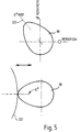
- Figure 5 shows the position of zero degree reference on a cam 18 which defines the position from which relative angles for the control of the synchronisation between the cam and the grinding wheel are determined.
- the cam 18 has a maximum radius with respect to the centre of cam rotation as shown by line 20. This radius is chosen to be a zero degree reference line.
- the cam 18 is defined at zero degrees with respect to the grinding wheel 22 when the cam zero reference is pointing horizontally towards the grinding wheel centre 22.
- the zero degree reference line 20 is further referenced to an angular measuring system coincident with the axis of cam rotation. Rotation of the reference line 20 relative to its initial position produces an angular rotation which is measured by the angular measuring system.
- the relative angle is read by a computer controlling the grinding machine and a signal fed from the computer to the grinding machine so as to synchronise movement of the cam 18 and the grinding wheel 22.
- Figure 6 describes the steps required to synchronise the grinding of the cam 18 with rotation of the grinding wheel 22.
- the cam 18 is indexed to zero, plus or minus an angular offset.
- the offset is stored in the controlling computer by a machine operator. The size of the offset depends on the direction of rotation of the cam 18 during grinding, i.e. whether the rotation is clockwise or anti-clockwise.
- the grinding wheel 22 is moved forward until its surface is positioned so as to contact the rotating cam 18 when the maximum throw of the cam, as defined along line 20 in Figure 5, aligns with the line joining the centre of rotation of the cam 18 and the grinding wheel 22.
- Cam rotation in the desired direction of grinding is started and when the cam 18 is at zero degrees with respect to the grinding wheel 22, the latter 22 is moved linearly with respect to the horizontal axis along which the zero degree reference to the cam was initially defined.
- the grinding wheel movement is controlled by (cam angle/grinding wheel position) coordinates as specified by the controlling computer in accordance with the cam profile to be ground. After 360 degrees of rotation when the maximum radius of the cam is back at the zero degrees reference position, the linear motion of the grinding wheel 22 is stopped.
- the cam 18 is rotated through an angle controlled by the machine control computer, as specified by a machine operator, and stopped.
- the grinding wheel 22 no longer contacts the cam 18 at any position and the wheel 22 is retracted away from the cam 18.
- the roughly ground cam is then removed.
Landscapes
- Engineering & Computer Science (AREA)
- Mechanical Engineering (AREA)
- Grinding And Polishing Of Tertiary Curved Surfaces And Surfaces With Complex Shapes (AREA)
Description
Claims (7)
- A method of rough grinding a cam within a maximum of two rotations of a cam workpiece (12) relative to a grinding wheel, wherein rotation of the cam and operation of the cam/grinding wheel infeed/outfeed are synchronised to cause the grinding wheel first to contact and engage the workpiece and, as infeed continues, to remove material so that the radius of the peak of the cam lobe (14) is attained at the intended position of the peak as it becomes aligned with the grinding wheel with rotation of the workpiece, and thereafter, by continued rotation of the workpiece and infeed/outfeed operation, remove material from the workpiece so as to attain the required contour of the remainder of the cam, and finally to break contact with the ground face of the cam, characterised in that the first contact between the workpiece (12) and the grinding wheel (10) is ahead of the intended position of the peak of the cam lobe (14) therearound, and in that contact with the ground face is finally broken when or after the peak of the lobe has become aligned with the grinding wheel for a second time but before the third such alignment.
- A method of rough grinding according to claim 1, further comprising the step of finish grinding using a grinding wheel.
- A method of rough grinding according to claim 1, further comprising the step of finish grinding using an abrasive belt.
- A method of rough grinding a cam having a cam lobe (14) according to any one of claims 1 to 3 comprising the further step of surface hardening the cam (12) before finish grinding.
- A grinding machine for rough grinding a cam, comprising control means for synchronising workpiece rotation and infeed/outfeed movement of a grinding wheel (10) and cam (12) so as to achieve rough grinding of the cam to a required contour, characterised in that, for carrying out the method according to claim 1, the control means causes the grinding wheel first to contact the cam ahead of the intended position of the peak of the cam lobe (14).
- A grinding machine according to claim 5, wherein camshaft indexing along its axis from one cam workpiece (12) to the next is synchronised relative to the infeed/outfeed movements of the grinding wheel (10) and to the camshaft, so that the next cam workpiece is engaged by the grinding wheel.
- A camshaft grinding machine comprising a bed, means for supporting and rotating a camshaft to be ground relative to a grinding wheel, infeed/outfeed drive means for moving the cam and grinding wheel relative to each other, first position sensing means for determining the distance between the longitudinal axis of the camshaft and the nearest point thereto on the surface of the grinding wheel, second position sensing means for determining the angular position of the rotating camshaft, control means responsive to signals from the two position sensing means to control the drive means, means containing radius data relative to rotational shaft position and means for utilising the radius/position data to control the infeed/outfeed drive means to remove more or less material from the camshaft to attain the desired profile around the camshaft in not more than two rations of the camshaft, characterised in that the drive means are controlled such that the wheel and the camshaft are caused to engage just prior to when the region of maximum radius of the cam lobe to be ground becomes aligned with a plane containing the axis of the wheel and the axis of the camshaft.
Applications Claiming Priority (3)
| Application Number | Priority Date | Filing Date | Title |
|---|---|---|---|
| GB9401462 | 1994-01-26 | ||
| GB9401462A GB9401462D0 (en) | 1994-01-26 | 1994-01-26 | Improvements in and relating to grinding |
| PCT/GB1995/000146 WO1995020467A1 (en) | 1994-01-26 | 1995-01-25 | Improvements in or relating to grinding |
Publications (2)
| Publication Number | Publication Date |
|---|---|
| EP0741630A1 EP0741630A1 (en) | 1996-11-13 |
| EP0741630B1 true EP0741630B1 (en) | 1999-03-03 |
Family
ID=10749343
Family Applications (1)
| Application Number | Title | Priority Date | Filing Date |
|---|---|---|---|
| EP95906426A Expired - Lifetime EP0741630B1 (en) | 1994-01-26 | 1995-01-25 | Improvements in or relating to grinding |
Country Status (6)
| Country | Link |
|---|---|
| EP (1) | EP0741630B1 (en) |
| AU (1) | AU1462295A (en) |
| DE (1) | DE69508060T2 (en) |
| ES (1) | ES2128040T3 (en) |
| GB (2) | GB9401462D0 (en) |
| WO (1) | WO1995020467A1 (en) |
Families Citing this family (3)
| Publication number | Priority date | Publication date | Assignee | Title |
|---|---|---|---|---|
| GB2357722B (en) * | 1999-10-27 | 2003-05-07 | Unova Uk Ltd | Workpiece grinding method which achieves a constant stock removal rate |
| CN102229083A (en) * | 2011-06-08 | 2011-11-02 | 潘旭华 | Grinding method for concave-convex wheel |
| CN103707160B (en) * | 2014-01-13 | 2016-01-20 | 北京信息科技大学 | Camshaft grinding transition profile planing method |
Family Cites Families (4)
| Publication number | Priority date | Publication date | Assignee | Title |
|---|---|---|---|---|
| US4443976A (en) * | 1982-01-29 | 1984-04-24 | Litton Industrial Products, Inc. | Cylindrical grinding machine |
| DE3529099A1 (en) * | 1985-08-14 | 1987-02-19 | Fortuna Werke Maschf Ag | METHOD AND DEVICE FOR CHIP-EDITING A SURFACE OF PROFILES WITH A CONTOUR DIFFERENT FROM A CIRCULAR SHAPE, IN PARTICULAR CAMSHAFT |
| HU209638B (en) * | 1989-10-27 | 1994-09-28 | Miskolci Egyetem | Method and apparatus for generating machining with abrasive belt |
| US5165202A (en) * | 1991-10-18 | 1992-11-24 | Spindel Jr Gilbert D | Methods and apparatus for making spectacle frame lens patterns |
-
1994
- 1994-01-26 GB GB9401462A patent/GB9401462D0/en active Pending
-
1995
- 1995-01-25 GB GB9501409A patent/GB2285937B/en not_active Expired - Fee Related
- 1995-01-25 AU AU14622/95A patent/AU1462295A/en not_active Abandoned
- 1995-01-25 DE DE69508060T patent/DE69508060T2/en not_active Expired - Fee Related
- 1995-01-25 ES ES95906426T patent/ES2128040T3/en not_active Expired - Lifetime
- 1995-01-25 EP EP95906426A patent/EP0741630B1/en not_active Expired - Lifetime
- 1995-01-25 WO PCT/GB1995/000146 patent/WO1995020467A1/en not_active Ceased
Also Published As
| Publication number | Publication date |
|---|---|
| GB2285937B (en) | 1997-08-20 |
| EP0741630A1 (en) | 1996-11-13 |
| WO1995020467A1 (en) | 1995-08-03 |
| DE69508060T2 (en) | 1999-07-01 |
| GB9401462D0 (en) | 1994-03-23 |
| AU1462295A (en) | 1995-08-15 |
| GB2285937A (en) | 1995-08-02 |
| DE69508060D1 (en) | 1999-04-08 |
| GB9501409D0 (en) | 1995-03-15 |
| ES2128040T3 (en) | 1999-05-01 |
Similar Documents
| Publication | Publication Date | Title |
|---|---|---|
| US10583507B2 (en) | Method for machining a workpiece, tool arrangement and tooth cutting machine | |
| US4961289A (en) | Machine tool for fine machining the tooth flanks of pretoothed gearwheels | |
| US4747236A (en) | Method for working, by metal-cutting processes, the surfaces of profiles having a non-circular contour, in particular camshafts | |
| CA2221156A1 (en) | Improvements in and relating to machine tools | |
| US5919081A (en) | Method and apparatus for computer numerically controlled pin grinder gauge | |
| EP0085225B1 (en) | Cylindrical grinding machine | |
| EP1621287B1 (en) | Method and apparatus for grinding cams with a re-entrant surface | |
| EP0741630A1 (en) | Improvements in or relating to grinding | |
| EP1235662B1 (en) | Computer controlled grinding machine | |
| US4744179A (en) | Process for controlling tool infeed at machining start of a gear cutting machine | |
| US20230264280A1 (en) | Method for machining and producing a toothed portion on a workpiece | |
| EP0675780B1 (en) | Workpiece grinding apparatus and method | |
| US5191739A (en) | Method and apparatus for lapping gear teeth while changing at least one of load torque, rotating speeds and rate of teeth contact point movement of the gears | |
| US5616070A (en) | Work drive orienting system for machine tool | |
| JP3850224B2 (en) | Grinding method and numerically controlled grinding machine | |
| US3977126A (en) | Grinding machine | |
| JPH0632894B2 (en) | Cam grinding equipment | |
| JP7863013B2 (en) | Grinding machine and grinding method | |
| JPH0760622A (en) | Grinding device for twist end mill | |
| GB2273899A (en) | Grinding method and apparatus | |
| JPS62107947A (en) | Automatic grinding method for broach | |
| SU808329A1 (en) | Machine for faceting the insets of jewellery articles | |
| JP3348877B2 (en) | Traverse grinding method for surface grinder | |
| US20030097747A1 (en) | Method of machining a part | |
| SU965717A1 (en) | Apparatus for charging parts |
Legal Events
| Date | Code | Title | Description |
|---|---|---|---|
| PUAI | Public reference made under article 153(3) epc to a published international application that has entered the european phase |
Free format text: ORIGINAL CODE: 0009012 |
|
| 17P | Request for examination filed |
Effective date: 19960418 |
|
| AK | Designated contracting states |
Kind code of ref document: A1 Designated state(s): DE ES FR IT |
|
| RIN1 | Information on inventor provided before grant (corrected) |
Inventor name: MIDGLEY, CLIVE J. S. Inventor name: BARTLETT, CHRISTOPHER D. |
|
| 17Q | First examination report despatched |
Effective date: 19971126 |
|
| GRAG | Despatch of communication of intention to grant |
Free format text: ORIGINAL CODE: EPIDOS AGRA |
|
| GRAG | Despatch of communication of intention to grant |
Free format text: ORIGINAL CODE: EPIDOS AGRA |
|
| GRAG | Despatch of communication of intention to grant |
Free format text: ORIGINAL CODE: EPIDOS AGRA |
|
| GRAH | Despatch of communication of intention to grant a patent |
Free format text: ORIGINAL CODE: EPIDOS IGRA |
|
| GRAH | Despatch of communication of intention to grant a patent |
Free format text: ORIGINAL CODE: EPIDOS IGRA |
|
| RAP1 | Party data changed (applicant data changed or rights of an application transferred) |
Owner name: UNOVA U.K. LIMITED |
|
| GRAA | (expected) grant |
Free format text: ORIGINAL CODE: 0009210 |
|
| ITF | It: translation for a ep patent filed | ||
| AK | Designated contracting states |
Kind code of ref document: B1 Designated state(s): DE ES FR IT |
|
| REF | Corresponds to: |
Ref document number: 69508060 Country of ref document: DE Date of ref document: 19990408 |
|
| REG | Reference to a national code |
Ref country code: ES Ref legal event code: FG2A Ref document number: 2128040 Country of ref document: ES Kind code of ref document: T3 |
|
| ET | Fr: translation filed | ||
| PLBE | No opposition filed within time limit |
Free format text: ORIGINAL CODE: 0009261 |
|
| STAA | Information on the status of an ep patent application or granted ep patent |
Free format text: STATUS: NO OPPOSITION FILED WITHIN TIME LIMIT |
|
| 26N | No opposition filed | ||
| PGFP | Annual fee paid to national office [announced via postgrant information from national office to epo] |
Ref country code: FR Payment date: 20060117 Year of fee payment: 12 |
|
| PGFP | Annual fee paid to national office [announced via postgrant information from national office to epo] |
Ref country code: ES Payment date: 20060126 Year of fee payment: 12 |
|
| PGFP | Annual fee paid to national office [announced via postgrant information from national office to epo] |
Ref country code: IT Payment date: 20060131 Year of fee payment: 12 |
|
| PGFP | Annual fee paid to national office [announced via postgrant information from national office to epo] |
Ref country code: DE Payment date: 20060228 Year of fee payment: 12 |
|
| REG | Reference to a national code |
Ref country code: FR Ref legal event code: TP |
|
| PG25 | Lapsed in a contracting state [announced via postgrant information from national office to epo] |
Ref country code: DE Free format text: LAPSE BECAUSE OF NON-PAYMENT OF DUE FEES Effective date: 20070801 |
|
| REG | Reference to a national code |
Ref country code: FR Ref legal event code: ST Effective date: 20070930 |
|
| REG | Reference to a national code |
Ref country code: ES Ref legal event code: FD2A Effective date: 20070126 |
|
| PG25 | Lapsed in a contracting state [announced via postgrant information from national office to epo] |
Ref country code: FR Free format text: LAPSE BECAUSE OF NON-PAYMENT OF DUE FEES Effective date: 20070131 |
|
| PG25 | Lapsed in a contracting state [announced via postgrant information from national office to epo] |
Ref country code: ES Free format text: LAPSE BECAUSE OF NON-PAYMENT OF DUE FEES Effective date: 20070126 |
|
| PG25 | Lapsed in a contracting state [announced via postgrant information from national office to epo] |
Ref country code: IT Free format text: LAPSE BECAUSE OF NON-PAYMENT OF DUE FEES Effective date: 20070125 |