EP0741340A1 - Method and apparatus for liquid image development and transfer - Google Patents
Method and apparatus for liquid image development and transfer Download PDFInfo
- Publication number
- EP0741340A1 EP0741340A1 EP96303092A EP96303092A EP0741340A1 EP 0741340 A1 EP0741340 A1 EP 0741340A1 EP 96303092 A EP96303092 A EP 96303092A EP 96303092 A EP96303092 A EP 96303092A EP 0741340 A1 EP0741340 A1 EP 0741340A1
- Authority
- EP
- European Patent Office
- Prior art keywords
- charge
- bearing surface
- toner
- intermediate transfer
- nip
- Prior art date
- Legal status (The legal status is an assumption and is not a legal conclusion. Google has not performed a legal analysis and makes no representation as to the accuracy of the status listed.)
- Granted
Links
- 239000007788 liquid Substances 0.000 title claims abstract description 185
- 238000012546 transfer Methods 0.000 title claims abstract description 89
- 238000000034 method Methods 0.000 title claims abstract description 88
- 238000011161 development Methods 0.000 title description 27
- 230000008569 process Effects 0.000 claims abstract description 71
- 238000003384 imaging method Methods 0.000 claims abstract description 32
- 108091008695 photoreceptors Proteins 0.000 claims abstract description 23
- 239000007787 solid Substances 0.000 claims description 45
- 230000005684 electric field Effects 0.000 claims description 21
- 238000011144 upstream manufacturing Methods 0.000 claims description 4
- 239000011248 coating agent Substances 0.000 claims description 3
- 238000000576 coating method Methods 0.000 claims description 3
- 239000000463 material Substances 0.000 description 24
- 238000004140 cleaning Methods 0.000 description 9
- 239000000976 ink Substances 0.000 description 9
- 239000002245 particle Substances 0.000 description 9
- 238000009826 distribution Methods 0.000 description 6
- 239000000758 substrate Substances 0.000 description 6
- 239000004215 Carbon black (E152) Substances 0.000 description 4
- 238000010438 heat treatment Methods 0.000 description 4
- 229930195733 hydrocarbon Natural products 0.000 description 4
- 150000002430 hydrocarbons Chemical class 0.000 description 4
- 230000008901 benefit Effects 0.000 description 3
- 230000003750 conditioning effect Effects 0.000 description 3
- 230000000694 effects Effects 0.000 description 3
- 238000013508 migration Methods 0.000 description 3
- 230000005012 migration Effects 0.000 description 3
- 238000000926 separation method Methods 0.000 description 3
- 238000010008 shearing Methods 0.000 description 3
- 230000001143 conditioned effect Effects 0.000 description 2
- 238000007599 discharging Methods 0.000 description 2
- 239000012530 fluid Substances 0.000 description 2
- 239000008187 granular material Substances 0.000 description 2
- 239000000843 powder Substances 0.000 description 2
- 238000002360 preparation method Methods 0.000 description 2
- 238000012545 processing Methods 0.000 description 2
- 230000001360 synchronised effect Effects 0.000 description 2
- 229910000838 Al alloy Inorganic materials 0.000 description 1
- 229910001370 Se alloy Inorganic materials 0.000 description 1
- BUGBHKTXTAQXES-UHFFFAOYSA-N Selenium Chemical class [Se] BUGBHKTXTAQXES-UHFFFAOYSA-N 0.000 description 1
- 230000009471 action Effects 0.000 description 1
- 230000015572 biosynthetic process Effects 0.000 description 1
- 230000015556 catabolic process Effects 0.000 description 1
- 239000003086 colorant Substances 0.000 description 1
- 239000004020 conductor Substances 0.000 description 1
- 238000006731 degradation reaction Methods 0.000 description 1
- 238000001962 electrophoresis Methods 0.000 description 1
- 238000001704 evaporation Methods 0.000 description 1
- 230000008020 evaporation Effects 0.000 description 1
- 238000002474 experimental method Methods 0.000 description 1
- 230000007246 mechanism Effects 0.000 description 1
- 230000001846 repelling effect Effects 0.000 description 1
- 238000000518 rheometry Methods 0.000 description 1
- 229920003002 synthetic resin Polymers 0.000 description 1
- 239000000057 synthetic resin Substances 0.000 description 1
- 238000009827 uniform distribution Methods 0.000 description 1
- 238000012800 visualization Methods 0.000 description 1
Images

Classifications
-
- G—PHYSICS
- G03—PHOTOGRAPHY; CINEMATOGRAPHY; ANALOGOUS TECHNIQUES USING WAVES OTHER THAN OPTICAL WAVES; ELECTROGRAPHY; HOLOGRAPHY
- G03G—ELECTROGRAPHY; ELECTROPHOTOGRAPHY; MAGNETOGRAPHY
- G03G15/00—Apparatus for electrographic processes using a charge pattern
- G03G15/14—Apparatus for electrographic processes using a charge pattern for transferring a pattern to a second base
- G03G15/16—Apparatus for electrographic processes using a charge pattern for transferring a pattern to a second base of a toner pattern, e.g. a powder pattern, e.g. magnetic transfer
- G03G15/1605—Apparatus for electrographic processes using a charge pattern for transferring a pattern to a second base of a toner pattern, e.g. a powder pattern, e.g. magnetic transfer using at least one intermediate support
- G03G15/161—Apparatus for electrographic processes using a charge pattern for transferring a pattern to a second base of a toner pattern, e.g. a powder pattern, e.g. magnetic transfer using at least one intermediate support with means for handling the intermediate support, e.g. heating, cleaning, coating with a transfer agent
-
- G—PHYSICS
- G03—PHOTOGRAPHY; CINEMATOGRAPHY; ANALOGOUS TECHNIQUES USING WAVES OTHER THAN OPTICAL WAVES; ELECTROGRAPHY; HOLOGRAPHY
- G03G—ELECTROGRAPHY; ELECTROPHOTOGRAPHY; MAGNETOGRAPHY
- G03G15/00—Apparatus for electrographic processes using a charge pattern
- G03G15/14—Apparatus for electrographic processes using a charge pattern for transferring a pattern to a second base
- G03G15/16—Apparatus for electrographic processes using a charge pattern for transferring a pattern to a second base of a toner pattern, e.g. a powder pattern, e.g. magnetic transfer
- G03G15/1605—Apparatus for electrographic processes using a charge pattern for transferring a pattern to a second base of a toner pattern, e.g. a powder pattern, e.g. magnetic transfer using at least one intermediate support
Definitions
- This invention relates to electrostatographic printing machines, and more particularly to a method and apparatus for simultaneously developing and transferring a liquid toner image onto an intermediate transfer member for subsequent conditioning thereon.
- a typical electrostatographic printing machine employs a photoconductive member that is sensitized by charging to a substantially uniform potential.
- the charged portion of the photoconductive member is exposed to the light image of a document.
- Exposure of the charged photoconductive member selectively dissipates the charge to record an electrostatic latent image.
- the electrostatic latent image corresponds to the informational areas of the document.
- the electrostatic latent image recorded on the photoconductive member is developed by contact with a developer material.
- the developer material can be a dry material comprising carrier granules having adhering toner particles.
- the latent image attracts the toner particles from the carrier granules to form a toner powder image on the photoconductive surface.
- the toner powder image is then transferred and permanently fused to a copy sheet.
- An electrostatic latent image also may be developed with a liquid developer material.
- the photoconductive surface is contacted with an insulating liquid carrier having dispersed finely divided marking particles.
- the electrical field associated with the electrostatic latent image attracts the marking particles to the photoconductive surface to form a visible image.
- Liquid developing imaging processes utilize a liquid developer typically having about 2 percent by weight of fine solid particulate toner material dispersed in a liquid carrier.
- the liquid carrier is typically a hydrocarbon.
- the image on the photoreceptor contains about 12 weight percent of particulate toner in liquid hydrocarbon carrier.
- percent solids in liquid should be increased to about 25 percent by weight. Increase in percent solids may be achieved by removing excess hydrocarbon liquid. However, excess hydrocarbon liquid must be removed in a manner that results in minimum degradation of the toner image.
- Prior art liquid ink development systems operate such that the photoconductor surface rotates through the developer bath to make contact with the toner.
- the toner particles are attracted to the latent electrostatic image on the photoconductor surface.
- the motion of the toner particles in the imagewise electric field is generally called electrophoresis and is well known in the art.
- the liquid carrier also wets the photoconductor surface. It is very difficult to transfer the toner image to paper without either first removing the liquid carrier from the photoconductor surface or using the liquid carrier to enable transfer to the paper and subsequently removing the liquid carrier from the paper. In both cases, the liquid carrier must be removed by processes that must include evaporation of the liquid carrier into the air, which causes airborne pollution.
- US-A-4,707,112, to Hartmann, November 17,1987 relates to an apparatus for developing an electrostatic latent image.
- the apparatus includes means for furnishing liquid developer material to the image in a development zone and means for dispersing the particles substantially uniformly in the liquid carrier of the liquid developer material at the entrance to the development zone so as to deflocculate marking particles.
- the dispersing means may comprise means for generating a pulsed electrical field in the developer material at the entrance to the development zone to induce movement of the marking particles and the liquid carrier.
- the generating means includes an electrode positioned at the entrance to the development zone and means for applying a pulsed voltage to the electrode to generate a pulsed electrical field in the developer material.
- One object of the present invention is to provide a method and apparatus for liquid image development and transfer which provides improvements over the prior art.
- an apparatus for simultaneously developing and transferring a liquid toner image includes a movable photoreceptor including a charge bearing surface having a first, uncharged electrical potential.
- the apparatus also includes mechanisms for forming a latent image electrostatically on the charge bearing surface such that the latent image includes charged areas each having a second electrical potential, and discharged areas each having the first, uncharged electrical potential of the charge bearing surface.
- the apparatus also includes a movable intermediate transfer member that forms a process nip with the charge bearing surface, and is biased to a third electrical potential between the first and the second potentials. The first, second and third electrical potentials are such as to create an electrical field within the process nip.
- the apparatus further includes a device for introducing charged liquid toner having a fourth electrical potential into the process nip such that the charged liquid toner is sandwiched within the electrical field in the process nip, and is caused by the electrical field to simultaneously form a toner image of image areas of the latent image on the intermediate transfer member, and a toner pattern of background areas of the latent image on the charge bearing surface of the photoreceptor.
- a method for simultaneously developing and transferring a liquid toner image includes the steps of moving a photoreceptor including a charge bearing surface having a first electrical potential, applying a uniform layer of charge having a second electrical potential onto the charge bearing surface, and imagewise dissipating charge from selected portions on the charge bearing surface to form a latent image electrostatically, such that the charge-dissipated portions of the charge bearing surface have the first electrical potential.
- the method also includes the steps of moving an intermediate transfer member biased to a third electrical potential between the first and second potentials, into a nip forming relationship with the moving imaging member to form a process nip.
- the method further includes the step of introducing charged liquid toner having a fourth potential, into the process nip, and sandwiching a layer of the charged liquid toner within the process nip, such that the sandwiched liquid toner simultaneously develops image portions of the latent image onto the intermediate transfer member, and background portions of the latent image on the charge bearing surface of the photoreceptor.
- Drum 10 includes a photoconductive surface 16 on which a uniform layer of charge, for example, positive charge, is applied by a corona device 18.
- the charged surface 16 is imagewise exposed by exposure means including a lens 20 to form a latent image on the surface 16.
- the apparatus 22 includes development electrodes 24 for creating a desired electrical field for latent image development.
- a rotating roller 26 operates to meter and partially reduces the amount of liquid in the developed liquid developer image now on surface 16.
- a rigidizing roller 30 is used to compress and rigidize the liquid developer forming the developed image
- a squeegee roller 32 is used to remove excess liquid from the developed image prior to image transfer.
- An intermediate transfer member 40 is then provided for receiving the rigidized liquid image from the surface 16 for subsequent transfer to a receiving image substrate 42, such as a copy sheet of paper. Following transfer of the image from surface 16, it is cleaned by a roller 50 and wiper blade 52 to be ready for using in forming another image.
- the apparatus 100 includes a movable latent image bearing member 110 that has a charge bearing surface 112.
- the image bearing member 110 for example can be a drum rotatable about an axis in the direction of the arrow 114, as shown, by a first drive or moving means M1 and at a first velocity (V1).
- the latent image bearing member 110 can also be a continuous flexible belt that is trained over a series of rollers, and is movable in the same direction as shown.
- the latent image bearing member 110 can be any suitable charge and image bearing member, even one suitable for ionographic latent image formation. In either case, the member 110 is maintained at an uncharged, first electrical potential shown as P1.
- the apparatus 100 also includes a movable intermediate toner image receiving and transfer member 116 that is biased to a second electrical potential P2 shown for example as ground 118.
- a portion of the intermediate member 116 is wrapped over a portion of the charge bearing surface 112 to form a long process nip 120 with the charge bearing surface 112 of member 110.
- the intermediate member 116 is electrically conductive, or it can be comprised of a dielectric substrate that has an electrically conductive overcoating. According to the present invention, at least the latent image bearing member 110 or the intermediate member 116 has to be flexible in order to produce the long wrap nip 120.
- the intermediate member 116 is shown as a flexible belt that is trained and held in controlled tension about a series of rollers R1, R2, R3 and R4 for example, and is movable in the direction of the arrow 122 by a second drive or moving means M2. As shown, it is important that within the process nip 120, the intermediate transfer member 116 is being moved by the second moving means M2 in the same direction as the charge bearing surface 112 of the member 110, and at a second velocity (V2).
- the second velocity (V2) preferably is equal to the first velocity (V1) in order to achieve synchronous movement of the charge bearing surface 112 and the intermediate member 116 through the process nip 120.
- the long wrap, process nip 120 has a radius of curvature
- the movable intermediate member 116 has and follows a concave path through the curvature of the nip, as shown.
- latent image bearing and photoconductive surface 112 of the member 110 therefore has and follows a convex path as shown within the process nip 120.
- the apparatus 100 also includes means for forming a latent image electrostatically on the charge bearing surface 112.
- the means for forming a latent image can be ionographic, or as shown, it can be electrostatic, and so includes (a) a corona generating device 126 for applying a uniform layer of charge having a desired third electrical potential P3, and a desired polarity, for example a negative polarity, onto the charge bearing surface 112 of member 110.
- the means for forming a latent image electrostatically also includes discharging means 128 for imagewise discharging portions of the uniformly charged surface 112 to form a desired latent image.
- the latent image is so formed such that it includes, for example, undischarged image areas (as in a CAD process) which each have the third electrical potential P3, and discharged background areas which each have the same electrical potential P1 as the uncharged member 110.
- the first, second and third electrical potentials P1, P2, and P3 are selected such that P2, the potential of the intermediate member 116, lies between P1 and P3 of the member 110, so as to combine with charged liquid toner (as will be described below) to create electrical fields within the process nip 120 for simultaneous development and transfer of liquid toner images according to the present invention.
- the latent image can also be so formed such that it includes, for example, discharged image areas (as in a DAD process) which each have the same electrical potential P1 as the uncharged member 110, and undischarged background areas which each have the third electrical potential P3.
- the imagewise discharged portions of the charge bearing surface 112 comprise the image areas of the latent image
- the imagewise undischarged portions of the charge bearing surface 112 comprise the background areas of the latent image.
- the apparatus 100 includes means 130 for introducing charged liquid toner 132 into the process nip 120.
- the means 130 includes a source 134 of charged liquid toner or ink which preferably has a solids content between 2% - 25% by volume.
- the charged liquid toner 132 has a potential P5 and a polarity that are relatively the same as those of the first, uncharged, electrical potential P1 of surface 112, and that are relatively opposite to those of the third, charged electrical potential P3 of surface 112.
- the source 134 can be a liquid developer unit including a cleaning blade 135, and a metering blade 136.
- the means 130 also includes, according to the present invention, the intermediate member 116 which is moved through the liquid developer unit 134 to receive a uniform coated layer of liquid toner for transport through the process nip 120.
- the means 130 for introducing charged liquid toner into the process nip 120 includes means 134, 136 and 116 for applying a uniform coating of liquid toner onto the intermediate member 116, at a point upstream of the process nip 120, relative to movement of the intermediate member 116.
- the layer of liquid toner brought into the nip 120 on the surface of intermediate member 116 is there sandwiched between the intermediate member 116 and the latent image bearing surface 112 as both move through the process nip 120, in the presence of electrical fields set up due to the various potentials P1 to P4 or P5.
- the simultaneous develop-and-transfer behavior of the sandwiched liquid toner within the process nip 120 will be described with particular reference to FIG.
- the undischarged image areas of the latent image with a potential of -300v will clearly be "like” in polarity and potential to the toner solids of the liquid toner, also at -300v.
- the behavior of the various components in these areas will be for the surface 112 to repel the toner solids towards the intermediate member 116, and the intermediate member 116 which is biased at P2, ground will tend additively to attract the same toner solids away from the repelling surface 112.
- toner solids representative of the image areas of the latent image will form and be held electrostatically on the intermediate member 116.
- the discharged background areas of the latent image with a potential of +300v will be clearly opposite in polarity and potential to the toner solids of the liquid toner with a potential of -300v.
- the behavior of the various components in these background areas will clearly be opposite of what takes place in the undischarged image areas.
- the surface 112 will instead attract the toner solids in these background areas away from the intermediate member 116.
- toner solids representative of the background areas of the latent image will form and be held electrostatically onto the surface 112.
- each portion of the segmented portions as illustrated includes a first layer SL made up primarily of toner solids attracted as described above to either the intermediate member 116 or to the surface 112, and a separate second layer LL consisting mainly of clear carrier liquid left behind after the toner solids have been attracted as above.
- segmented portions of liquid toner in the image areas of the latent image will each comprise a first layer SL of toner solids that is in contact with the intermediate member 116, and a separate second layer LL, mainly of clear carrier liquid that is in contact with the charge bearing surface 112.
- segmented portions of liquid toner in the background areas of the latent image will each comprise a separate second layer LL of mainly clear carrier liquid in contact with the intermediate member 116, and a first layer SL of toner solids in contact with charge bearing surface 112.
- the process nip 120 has an entrance side and point XX, and exit side and point YY.
- the intermediate member 116 and the latent image bearing member 110 including the charge bearing surface 112 are mounted so as to be moving, at an entrance, point XX, of the process nip 120, in the same direction into the nip. However, they are mounted for separating movement, at the exit point YY, away from each other and in substantially opposed directions.
- the separating movement is such that upon separation of the surface 112 and the intermediate member 116 at the exit point YY, each of the segmented portions of sandwiched liquid toner (comprising a solids layer SL, and a liquid layer LL) will "split"at the liquid layer LL thereof from the surface contacting such liquid layer.
- toner image areas with the liquid layers contacting the surface 112 will split at the surface 112 leaving essentially clear liquid on the surface 112 in such areas, while the toner solids layers SL thereof making up the desired toner image from the process will separate and remain on the intermediate member 116. This in effect has been achieved within the nip 120 in a simultaneous develop-and-transfer manner.
- the split of the solids and liquid layers in the background areas will be quite the opposite to that in the image areas. As such, the splits will occur on the intermediate member 116, leaving essentially clear liquid thereon, while the toner solids layer thereof will remain on the surface 112 for subsequent removal.
- the above process is such that the sandwiched liquid toner within the electrical fields in the nip 120, simultaneously forms and transfers a liquid toner pattern, corresponding to background areas of the latent image, on the charge bearing surface 112.
- the sandwiched liquid toner within the electrical fields in the nip 120 also simultaneously forms and transfers a liquid toner pattern, corresponding to image areas of the latent image, on the intermediate member 116.
- the apparatus 100 therefore includes a cleaning device 140 that is mounted downstream of the exit point YY of the process nip 120 for cleaning and removing liquid toner solids from the charge bearing surface 112, in preparation for reuse.
- the liquid toner image developed and transferred on the intermediate member 116 remains electrostatically attached or tacked to the member 116 downstream of the exit point YY, relative to movement of the member 116.
- the apparatus 100 therefore includes means such as a blotter roll 144, and a heat source 146, for conditioning the liquid toner image directly on the intermediate member 116. Conditioning the image on the intermediate member 116 as such is particularly advantageous since heat can be used on the member 116 without damaging the latent image bearing photoconductive member 110, and surface 112.
- the apparatus 100 includes a transfer nip 150 that is formed in part by the intermediate member 116 and a back up roller 152 for transferring the conditioned liquid toner image from the intermediate member 116 onto a receiving substrate, such as copy sheet 154.
- the transfer nip 150 may include a heating means 160 for simultaneously heating and fixing the transferred liquid toner image onto the copy sheet 154.
- a method for simultaneously developing and transferring a liquid toner image in a liquid toner apparatus 100 includes the steps of moving an imaging member 110 that is biased to a first potential and includes a charge bearing surface 112, applying a uniform layer of charge having a second electrical potential onto the charge bearing surface 112, and imagewise dissipating charge from selected portions on the charged surface in order to form a latent image electrostatically on such surface.
- the method also includes the steps of moving an intermediate member 116 biased to a third electrical potential to form a process nip 120 with the moving imaging member 110, introducing charged liquid toner having a fourth potential into the process nip, and sandwiching a layer of the liquid toner within the process nip 120 and electrical fields due to the various potentials, such that the sandwiched liquid toner simultaneously develops the latent image and transfers the developed image onto the intermediate member 116.
- a multicolor embodiment of a liquid electrophotographic simultaneous development and transfer apparatus 200 is illustrated and includes a continuous transfer belt, designated generally by reference numeral 202.
- the transfer belt 202 is trained for movement about a series of rollers R1, R2, ...Rn by a first drive such as MB.
- Continuous transfer belt 202 is moved as such in the direction of arrow 203, and is biased to a second electrical potential P2 according to the present invention.
- Four latent imaging units indicated generally by the reference numerals 204, 206, 208 and 210, are positioned about the periphery of continuous transfer belt 202. Each latent imaging unit is substantially identical to one another.
- latent imaging unit 204 uses a black colored liquid developer material while units 206, 208, and 210 use yellow, magenta and cyan colored liquid developer materials respectively. In as much as units 204, 206, 208 and 210 are similar, only unit 210 will be described here in detail.
- a drum 212 having a photoconductive surface 213 deposited on a conductive substrate rotates in the direction of arrow 214.
- the photoconductive surface 213 has uncharged, first potential P1, and is made from a selenium alloy with the conductive substrate being made from an electrically grounded aluminum alloy.
- Other suitable photoconductive surfaces and conductive substrates may also be employed.
- Drum 212 rotates in the direction of arrow 214 to advance successive portions of the photoconductive surface through the various processing stations disposed about its path of movement thereof.
- Corona generating device 216 charges the photoconductive surface of drum 212 to a relatively high, substantially uniform third electrical potential P3.
- Imaging unit 218 records an electrostatic latent image on the photoconductive surface of drum 212.
- the raster output scanner lays out the electrostatic latent image in a series of horizontal scan lines with each line having a specified number of pixels per inch.
- the raster output scanner employs a laser which generates a beam of light rays that are modulated by rotating polygon mirror blocks or solid state image modulator bars.
- the raster output scanner may use light emitting diode array write bars. In this way, an electrostatic latent image is recorded on the photoconductive surface of drum 212.
- the drum 212 of each imaging unit 204, 206, 208 and 210 forms a nip 220 with the transfer belt 202.
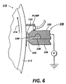
- the multicolor liquid apparatus 200 includes a device 230 (to be described below FIG. 6) for introducing the various colors of liquid toner 132 that is charged to a potential P4 or P5 as above, into the process nip 220 of each imaging unit.
- the device 230 for example, can be a liquid extruder as disclosed in US-A-5,355,201, relevant parts of which are incorporated here by reference.
- the liquid extruder 230 includes a first member 232 and a second member 234.
- An open-ended distribution channel 236 is formed in first member 232.
- Another distribution channel 238 extends in a direction substantially transverse to channel 236 which is located along the longitudinal axis of the rotatable drum 212.
- a first portion of the distribution channel 236 is connected to a supply of liquid developer material.
- a plurality of substantially equally spaced distribution channels 238 intersect with branches of channel 236.
- Distribution channels 238 receive liquid developer material from channel 236 and guide the liquid developer material to lip 242. The angle of ink distribution to channel 238 ensure that the liquid developer material coats the lip 242 with a film having a straight leading and trailing edge.
- Lip 242 is a surface of second member 234 which is substantially parallel to the longitudinal axis of drum 212 and defines a gap therebetween. The gap between lip 242 and drum 212 is less than the gap between the surface of first member 232 and drum 212. Lip 242 is used to apply liquid developer material of a substantially uniform thickness to the entire image frame including image and background areas of the latent image recorded on photoconductive surface 213 of drum 212. A metering pump is used to pump a requisite amount of liquid developer material for each electrostatic latent image from the supply of liquid developer material to liquid extruder 230.
- the device 230 is a source of charged liquid toner or ink, just as was the source 134 FIG. 2.
- the charged liquid toner 132 will have a potential P5 and a polarity that are relatively the same as those of the first, uncharged, electrical potential P1 of surface 213 of drum 212. As such, it is relatively opposite to the third, charged electrical potential P3 of surface 213.
- the device 230 thus applies a uniform coating of liquid toner onto the entire imaged frame of surface 213, at a point upstream of the process nip 220, when considered relative to movement of the drum 212.
- the layer of charged liquid toner is brought into the nip 220 on the surface of drum 212, where it is sandwiched according to the present invention as described above between the drum 212 and the surface transfer belt 202, and is moved through the process nip 220, in the presence of electrical fields set up due to the various electrical potentials P1 to P4 or P5.
- segmented portions of cyan color liquid toner, in the image areas of the latent image will each comprise a first layer SL of toner solids that is in contact with the transfer belt 202, and a separate second layer LL, mainly of clear carrier liquid that is in contact with the charge bearing surface 213 of drum 212.
- segmented portions of cyan liquid toner in the background areas of the latent image will each comprise a separate second layer LL of mainly clear carrier liquid that is in contact with the transfer belt 202, and a first layer SL of toner solids in contact with charge bearing surface 213.
- each of the segmented portions of sandwiched cyan liquid toner (comprising a solids layer SL, and a liquid layer LL) will "split"at the liquid layer LL thereof from the surface contacting such liquid layer LL.
- desired cyan color toner image areas each having a toner solids layer SL contacting the surface of the transfer belt 202 and essentially clear liquid layer LL contacting the surface 213, will split at the surface 213 of drum 212.
- Such splitting leaves essentially only clear liquid layers on the surface 213 in such areas.
- the toner solids layers SL thereof which make up the desired toner image will thus separate from the surface 213, and remain on the transfer belt 202. This in effect has been achieved within the nip 220 in a simultaneous develop-and-transfer manner.
- the split of the solids and liquid layers in the background areas of the latent image will be quite opposite to the split in the image areas as described above.
- the splits in the background areas will occur at the clear liquid lyers LL on the transfer belt 202, thus leaving essentially clear liquid on the belt 202 in these areas.
- the toner solids layer SL thereof will thus remain as a cyan color toner pattern on the surface 213 of drum 212 for subsequent removal by a cleaning device 250.
- the extruder device 230 of the imaging unit 210 thus uses charged cyan colored liquid developer material, and a cyan toner image is simultaneously developed and transferred onto the belt 202.
- Latent imaging units 204, 206, and 208 similarly will use charged black, yellow, and magenta colored liquid developer materials, respectively.
- the amount of liquid carrier remaining on the liquid toner image on the transfer belt 202 may be more than is desirable for subsequent immediate operations.
- a roller 252 whose surface moves in a direction opposite to the direction of movement of the transfer belt 202, and that is spaced from the surface of belt 202,may be provided for shearing excessive liquid from the developed image without disturbing the image.
- continuous transfer belt 202 moves such image to the next imaging unit 208.
- a liquid toner image of a different color is similarly formed according to the present invention (and in superimposed registration as is well known) onto the transfer belt 202.
- a magenta liquid toner image is formed on the belt 202 at imaging unit 208 and in superimposed registration with the cyan liquid toner image previously formed thereon.
- a yellow liquid image is similarly formed at imaging unit 206, and finally, the black liquid toner image is similarly formed at imaging unit 204.
- the multicolor liquid toner image is subsequently transferred at a transfer nip 260 to a sheet of support material, e.g. a sheet of copy paper 154.
- a transfer nip 260 is formed in part by the continuous transfer belt 202 and by a back up roller 262.
- the transfer nip 260 may include a heating device 160 for simultaneously heating and fixing the transferred liquid toner image onto the copy sheet 154. After such fixing or fusing, the copy sheet 154 is advanced to catch tray 266 for subsequent removal from the printing machine by the operator.
- Cleaning station 270 may include a cleaning roller, formed of any appropriate synthetic resin driven in a direction opposite to the direction of movement of continuous transfer belt 202 so as to scrub the surface thereof clean.
- liquid carrier may be fed through a pipe onto the surface of the cleaning roller.
- a wiper blade may also be used to complete the cleaning of the surface of belt 202 in preparation for receiving another multicolor as above.
- a method and apparatus for simultaneously developing and transferring liquid toner images to an intermediate receiver member. This is accomplished by sandwiching liquid ink or toner in a nip formed by a photoreceptor carrying the electrostatic latent form of the image and by a synchronous speed conductive or dielectric overcoated conductor, intermediate belt which is biased at a voltage intermediate between the image potential and the background voltage of the photoreceptor. With appropriate biasing and image potential, it is possible to so form positive or negative images (using positive or negatively charged liquid toners).
- the images must be so formed on the belt using a convex shaped photoreceptor.
- the toner image formed on the belt would require blotting and for color products the process would have to be repeated several times.
- the process of the present invention can be referred to as a transdevelopment process, since it involves a simultaneous development and transfer that results in toner images being created directly on an intermediate member, not on the photoreceptor with subsequent transfer as is conventional.
- simultaneous development and transfer is enabled by creation of a development nip consisting of a photoreceptor and the transfer belt moving at the same speed and in the same direction. Liquid toner at approximately 2% - 25% solids is introduced into the nip.
- the photoreceptor normally biased at a first potential, is charged to a voltage or potential P3 (V-high), and is discharged in image areas to the first potential voltage P1 (V-low).
- the transfer belt which can be conductive or dielectric coated is at another potential or voltage P2 (V-mid) so that P2 lies between P3 (V-high) and P1 (V-low).
- P2 voltage
- the electric fields as such in conjunction with the charge on the toner, will force the charged toner in the process nip against the transfer belt in image areas. On the other hand, it will force the charged toner against the photoreceptor in background areas.
- the sandwiched toner forms solids layers of more concentrated toner on top or below layers of clear carrier liquid.
- the sandwiched toner will split in the regions of lowest viscosity, i.e., in the layers of clear carrier liquid.
- a first toner image is thus produced directly on the transfer belt, and can then be conditioned on the belt before the next and subsequent toner images are similarly transdeveloped onto the first toner image.
- the advantages of the transdevelopment process of the present invention include the fact that with a long process nip created by a large wrap of the belt over the photoreceptor (drum or belt) high viscosity inks can be transdeveloped directly onto the belt. Another advantage is that higher solids concentration inks can be used since toner will only be required to migrate a very short distance in a direction normal to the photoreceptor and belt surfaces. The ink layer will move through the nip with uniform velocity equal to the photoreceptor and belt velocity. The gap in the nip can be controlled by proper tension on the belt.
- the development process of the present invention is similar to that observed in parallel plate electrode development, including some ink visualization cells.
- parallel plate electrode development experiments highly concentrated toner layers were created by applied electric fields. Areas of clear carrier fluid resulting from toner migration were observed. A further important observation was that if the electrodes were separated apart while maintaining an applied voltage thereon, the sandwiched toner split occurred in the clear liquid layers leaving one electrode with the toner layer and the other with half of the clear liquid layer.
Abstract
Description
- This invention relates to electrostatographic printing machines, and more particularly to a method and apparatus for simultaneously developing and transferring a liquid toner image onto an intermediate transfer member for subsequent conditioning thereon.
- A typical electrostatographic printing machine employs a photoconductive member that is sensitized by charging to a substantially uniform potential. The charged portion of the photoconductive member is exposed to the light image of a document. Exposure of the charged photoconductive member selectively dissipates the charge to record an electrostatic latent image. The electrostatic latent image corresponds to the informational areas of the document. The electrostatic latent image recorded on the photoconductive member is developed by contact with a developer material. The developer material can be a dry material comprising carrier granules having adhering toner particles. The latent image attracts the toner particles from the carrier granules to form a toner powder image on the photoconductive surface. The toner powder image is then transferred and permanently fused to a copy sheet.
- An electrostatic latent image also may be developed with a liquid developer material. In a liquid development system, the photoconductive surface is contacted with an insulating liquid carrier having dispersed finely divided marking particles. The electrical field associated with the electrostatic latent image attracts the marking particles to the photoconductive surface to form a visible image.
- Liquid developing imaging processes utilize a liquid developer typically having about 2 percent by weight of fine solid particulate toner material dispersed in a liquid carrier. The liquid carrier is typically a hydrocarbon. In the developing process, the image is transferred to a receiver which may be an intermediate belt. The image on the photoreceptor contains about 12 weight percent of particulate toner in liquid hydrocarbon carrier. To improve the quality of transfer of developed image to receiver, percent solids in liquid should be increased to about 25 percent by weight. Increase in percent solids may be achieved by removing excess hydrocarbon liquid. However, excess hydrocarbon liquid must be removed in a manner that results in minimum degradation of the toner image.
- Prior art liquid ink development systems operate such that the photoconductor surface rotates through the developer bath to make contact with the toner. In these systems, the toner particles are attracted to the latent electrostatic image on the photoconductor surface. The motion of the toner particles in the imagewise electric field is generally called electrophoresis and is well known in the art. However, the liquid carrier also wets the photoconductor surface. It is very difficult to transfer the toner image to paper without either first removing the liquid carrier from the photoconductor surface or using the liquid carrier to enable transfer to the paper and subsequently removing the liquid carrier from the paper. In both cases, the liquid carrier must be removed by processes that must include evaporation of the liquid carrier into the air, which causes airborne pollution.
- US-A-4,707,112, to Hartmann, November 17,1987, relates to an apparatus for developing an electrostatic latent image. The apparatus includes means for furnishing liquid developer material to the image in a development zone and means for dispersing the particles substantially uniformly in the liquid carrier of the liquid developer material at the entrance to the development zone so as to deflocculate marking particles. The dispersing means may comprise means for generating a pulsed electrical field in the developer material at the entrance to the development zone to induce movement of the marking particles and the liquid carrier. The generating means includes an electrode positioned at the entrance to the development zone and means for applying a pulsed voltage to the electrode to generate a pulsed electrical field in the developer material.
- One object of the present invention is to provide a method and apparatus for liquid image development and transfer which provides improvements over the prior art.
- In accordance with one aspect of the present invention, there is provided an apparatus for simultaneously developing and transferring a liquid toner image. The apparatus includes a movable photoreceptor including a charge bearing surface having a first, uncharged electrical potential. The apparatus also includes mechanisms for forming a latent image electrostatically on the charge bearing surface such that the latent image includes charged areas each having a second electrical potential, and discharged areas each having the first, uncharged electrical potential of the charge bearing surface. The apparatus also includes a movable intermediate transfer member that forms a process nip with the charge bearing surface, and is biased to a third electrical potential between the first and the second potentials. The first, second and third electrical potentials are such as to create an electrical field within the process nip. The apparatus further includes a device for introducing charged liquid toner having a fourth electrical potential into the process nip such that the charged liquid toner is sandwiched within the electrical field in the process nip, and is caused by the electrical field to simultaneously form a toner image of image areas of the latent image on the intermediate transfer member, and a toner pattern of background areas of the latent image on the charge bearing surface of the photoreceptor.
- Pursuant to another aspect of the present invention, there is provided a method for simultaneously developing and transferring a liquid toner image. The method includes the steps of moving a photoreceptor including a charge bearing surface having a first electrical potential, applying a uniform layer of charge having a second electrical potential onto the charge bearing surface, and imagewise dissipating charge from selected portions on the charge bearing surface to form a latent image electrostatically, such that the charge-dissipated portions of the charge bearing surface have the first electrical potential. The method also includes the steps of moving an intermediate transfer member biased to a third electrical potential between the first and second potentials, into a nip forming relationship with the moving imaging member to form a process nip. The method further includes the step of introducing charged liquid toner having a fourth potential, into the process nip, and sandwiching a layer of the charged liquid toner within the process nip, such that the sandwiched liquid toner simultaneously develops image portions of the latent image onto the intermediate transfer member, and background portions of the latent image on the charge bearing surface of the photoreceptor.
- The present invention will be described further, by way of examples, with reference to the accompanying drawings, in which:
- Figure 1 is a prior art simplified sectional illustration of a conventional liquid development electrophotographic apparatus;
- Figure 2 is a schematic illustration of one embodiment of a liquid electrophotographic simultaneous development and transfer apparatus according to the present invention;
- Figure 3 is an enlarged schematic of a simultaneous development and transfer process nip of the apparatus of Figure 2;
- Figure 4 is an enlarged illustration of the image portions versus background portions separation of sandwiched charged liquid toner in the process nip of Figure 3;
- Figure 5 is a schematic illustration of a multicolor embodiment of a liquid electrophotographic simultaneous development and transfer apparatus according to the present invention;and
- Figure 6 is an illustration, partially in section, of a liquid toner introduction device for use with the apparatus of the present invention.
- Referring first to Figure 1, a prior art example of a conventional electrophotographic liquid development apparatus is illustrated and includes a
drum 10. Thedrum 10 is rotatable about anaxle 12 in the direction ofarrow 14.Drum 10 includes aphotoconductive surface 16 on which a uniform layer of charge, for example, positive charge, is applied by acorona device 18. As is well known, thecharged surface 16 is imagewise exposed by exposure means including alens 20 to form a latent image on thesurface 16. - Continued rotation of the
drum 10 brings the latent image into a development relationship with aliquid developer apparatus 22 that holds liquid developer. Theapparatus 22 includesdevelopment electrodes 24 for creating a desired electrical field for latent image development. Following such development, a rotatingroller 26 operates to meter and partially reduces the amount of liquid in the developed liquid developer image now onsurface 16. Next, a rigidizingroller 30 is used to compress and rigidize the liquid developer forming the developed image, and asqueegee roller 32 is used to remove excess liquid from the developed image prior to image transfer. - An
intermediate transfer member 40 is then provided for receiving the rigidized liquid image from thesurface 16 for subsequent transfer to a receivingimage substrate 42, such as a copy sheet of paper. Following transfer of the image fromsurface 16, it is cleaned by aroller 50 andwiper blade 52 to be ready for using in forming another image. - Referring now to Figure 2, a first embodiment of an
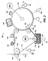
apparatus 100 for simultaneously developing and transferring a liquid toner image according to the present invention is illustrated. Theapparatus 100 includes a movable latentimage bearing member 110 that has acharge bearing surface 112. Theimage bearing member 110 for example can be a drum rotatable about an axis in the direction of thearrow 114, as shown, by a first drive or moving means M1 and at a first velocity (V1). Equally, the latentimage bearing member 110 can also be a continuous flexible belt that is trained over a series of rollers, and is movable in the same direction as shown. According to the present invention, the latentimage bearing member 110 can be any suitable charge and image bearing member, even one suitable for ionographic latent image formation. In either case, themember 110 is maintained at an uncharged, first electrical potential shown as P1. - The
apparatus 100 also includes a movable intermediate toner image receiving andtransfer member 116 that is biased to a second electrical potential P2 shown for example asground 118. Importantly according to the present invention, a portion of theintermediate member 116 is wrapped over a portion of thecharge bearing surface 112 to form along process nip 120 with thecharge bearing surface 112 ofmember 110. Theintermediate member 116 is electrically conductive, or it can be comprised of a dielectric substrate that has an electrically conductive overcoating. According to the present invention, at least the latentimage bearing member 110 or theintermediate member 116 has to be flexible in order to produce the long wrap nip 120. Accordingly, theintermediate member 116 is shown as a flexible belt that is trained and held in controlled tension about a series of rollers R1, R2, R3 and R4 for example, and is movable in the direction of thearrow 122 by a second drive or moving means M2. As shown, it is important that within the process nip 120, theintermediate transfer member 116 is being moved by the second moving means M2 in the same direction as thecharge bearing surface 112 of themember 110, and at a second velocity (V2). The second velocity (V2) preferably is equal to the first velocity (V1) in order to achieve synchronous movement of thecharge bearing surface 112 and theintermediate member 116 through the process nip 120. - Preferably, the long wrap, process nip 120 has a radius of curvature, and the movable
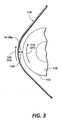
intermediate member 116 has and follows a concave path through the curvature of the nip, as shown. As such, latent image bearing andphotoconductive surface 112 of themember 110 therefore has and follows a convex path as shown within the process nip 120. - In accordance with the present invention, the
apparatus 100 also includes means for forming a latent image electrostatically on thecharge bearing surface 112. The means for forming a latent image can be ionographic, or as shown, it can be electrostatic, and so includes (a) acorona generating device 126 for applying a uniform layer of charge having a desired third electrical potential P3, and a desired polarity, for example a negative polarity, onto thecharge bearing surface 112 ofmember 110. The means for forming a latent image electrostatically also includes discharging means 128 for imagewise discharging portions of the uniformly chargedsurface 112 to form a desired latent image. The latent image is so formed such that it includes, for example, undischarged image areas (as in a CAD process) which each have the third electrical potential P3, and discharged background areas which each have the same electrical potential P1 as theuncharged member 110. The first, second and third electrical potentials P1, P2, and P3 are selected such that P2, the potential of theintermediate member 116, lies between P1 and P3 of themember 110, so as to combine with charged liquid toner (as will be described below) to create electrical fields within the process nip 120 for simultaneous development and transfer of liquid toner images according to the present invention. - Alternatively, the latent image can also be so formed such that it includes, for example, discharged image areas (as in a DAD process) which each have the same electrical potential P1 as the
uncharged member 110, and undischarged background areas which each have the third electrical potential P3. As such, the imagewise discharged portions of thecharge bearing surface 112 comprise the image areas of the latent image, and the imagewise undischarged portions of thecharge bearing surface 112 comprise the background areas of the latent image. - Further in accordance with the present invention, the
apparatus 100 includesmeans 130 for introducing chargedliquid toner 132 into the process nip 120. As shown, for example, themeans 130 includes asource 134 of charged liquid toner or ink which preferably has a solids content between 2% - 25% by volume. In a CAD process, i.e. charged area development process, the chargedliquid toner 132 has a potential P5 and a polarity that are relatively the same as those of the first, uncharged, electrical potential P1 ofsurface 112, and that are relatively opposite to those of the third, charged electrical potential P3 ofsurface 112. - The
source 134 can be a liquid developer unit including acleaning blade 135, and ametering blade 136. The means 130 also includes, according to the present invention, theintermediate member 116 which is moved through theliquid developer unit 134 to receive a uniform coated layer of liquid toner for transport through the process nip 120. Accordingly, themeans 130 for introducing charged liquid toner into the process nip 120 includesmeans intermediate member 116, at a point upstream of the process nip 120, relative to movement of theintermediate member 116. - Referring now to Figures 2 - 4, the layer of liquid toner brought into the
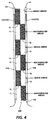
nip 120 on the surface ofintermediate member 116 is there sandwiched between theintermediate member 116 and the latentimage bearing surface 112 as both move through the process nip 120, in the presence of electrical fields set up due to the various potentials P1 to P4 or P5. The simultaneous develop-and-transfer behavior of the sandwiched liquid toner within the process nip 120 will be described with particular reference to FIG. 4 in which P1, the uncharged potential of thesurface 112, is +300v; P2 the potential of theintermediate member 116 is ground; P3 the charged potential of thesurface 112 is -300v; and P5, the potential of the charged toner solids of the liquid toner, in a CAD process is-300v. Upstream of thenip 120, theintermediate member 116 which is biased at ground would appear opposite in polarity relative to the liquid toner solids at -300v. Therefore at the liquid toner applying stage, the liquid toner will be attracted to, and held onto, theintermediate member 116 for transport into thenip 120. - Within the
nip 120, the undischarged image areas of the latent image with a potential of -300v will clearly be "like" in polarity and potential to the toner solids of the liquid toner, also at -300v. The behavior of the various components in these areas will be for thesurface 112 to repel the toner solids towards theintermediate member 116, and theintermediate member 116 which is biased at P2, ground will tend additively to attract the same toner solids away from the repellingsurface 112. As a result, toner solids representative of the image areas of the latent image will form and be held electrostatically on theintermediate member 116. - On the other hand, the discharged background areas of the latent image with a potential of +300v will be clearly opposite in polarity and potential to the toner solids of the liquid toner with a potential of -300v. The behavior of the various components in these background areas will clearly be opposite of what takes place in the undischarged image areas. For example, the
surface 112 will instead attract the toner solids in these background areas away from theintermediate member 116. As a result, toner solids representative of the background areas of the latent image will form and be held electrostatically onto thesurface 112. - As illustrated in FIG. 4, the behavior within the
nip 120 of the various components as described above, results in the sandwiched liquid toner being segmented into two types of portions, image area portions and background area portions. Each portion of the segmented portions as illustrated includes a first layer SL made up primarily of toner solids attracted as described above to either theintermediate member 116 or to thesurface 112, and a separate second layer LL consisting mainly of clear carrier liquid left behind after the toner solids have been attracted as above. - Accordingly, segmented portions of liquid toner in the image areas of the latent image will each comprise a first layer SL of toner solids that is in contact with the
intermediate member 116, and a separate second layer LL, mainly of clear carrier liquid that is in contact with thecharge bearing surface 112. On the other hand, segmented portions of liquid toner in the background areas of the latent image will each comprise a separate second layer LL of mainly clear carrier liquid in contact with theintermediate member 116, and a first layer SL of toner solids in contact withcharge bearing surface 112. - In the above process, rheological measurements have been made to confirm the fact that the viscosity of the liquid layer LL of each segmented portion of sandwiched liquid toner is by far less than that of the solids layer SL of the same segmented portion. The migration of attracted charged toner solids between the
surface 112 andintermediate member 116 is essentially in a normal or perpendicular direction. Preferably, the intermediate member should be tensioned to control the normal gap spacing between thesurface 112 andintermediate member 116 at between 15 - 20 microns. As a consequence liquid toners with high solids contents can be used since the solids will be caused as above to migrate to one surface leaving a low viscosity layer against an opposite surface. Additionally, high viscosity carrier fluids can be used with such high solid content liquid toners, since the migration of the solids therefrom will be only across a relatively short gap distance. - Referring still to FIGS. 2 - 4, it is noted that the process nip 120 has an entrance side and point XX, and exit side and point YY. As illustrated, the
intermediate member 116 and the latentimage bearing member 110 including thecharge bearing surface 112, are mounted so as to be moving, at an entrance, point XX, of the process nip 120, in the same direction into the nip. However, they are mounted for separating movement, at the exit point YY, away from each other and in substantially opposed directions. - According to the present invention, the separating movement is such that upon separation of the
surface 112 and theintermediate member 116 at the exit point YY, each of the segmented portions of sandwiched liquid toner (comprising a solids layer SL, and a liquid layer LL) will "split"at the liquid layer LL thereof from the surface contacting such liquid layer. As such, toner image areas with the liquid layers contacting thesurface 112 will split at thesurface 112 leaving essentially clear liquid on thesurface 112 in such areas, while the toner solids layers SL thereof making up the desired toner image from the process will separate and remain on theintermediate member 116. This in effect has been achieved within thenip 120 in a simultaneous develop-and-transfer manner. On the other hand, the split of the solids and liquid layers in the background areas will be quite the opposite to that in the image areas. As such, the splits will occur on theintermediate member 116, leaving essentially clear liquid thereon, while the toner solids layer thereof will remain on thesurface 112 for subsequent removal. - In other words, the above process is such that the sandwiched liquid toner within the electrical fields in the
nip 120, simultaneously forms and transfers a liquid toner pattern, corresponding to background areas of the latent image, on thecharge bearing surface 112. At the same time, the sandwiched liquid toner within the electrical fields in thenip 120, also simultaneously forms and transfers a liquid toner pattern, corresponding to image areas of the latent image, on theintermediate member 116. Theapparatus 100 therefore includes acleaning device 140 that is mounted downstream of the exit point YY of the process nip 120 for cleaning and removing liquid toner solids from thecharge bearing surface 112, in preparation for reuse. The liquid toner image developed and transferred on theintermediate member 116 remains electrostatically attached or tacked to themember 116 downstream of the exit point YY, relative to movement of themember 116. - In accordance to the present invention, the
apparatus 100 therefore includes means such as ablotter roll 144, and aheat source 146, for conditioning the liquid toner image directly on theintermediate member 116. Conditioning the image on theintermediate member 116 as such is particularly advantageous since heat can be used on themember 116 without damaging the latent image bearingphotoconductive member 110, andsurface 112. - As further shown, the
apparatus 100 includes a transfer nip 150 that is formed in part by theintermediate member 116 and a back uproller 152 for transferring the conditioned liquid toner image from theintermediate member 116 onto a receiving substrate, such ascopy sheet 154. As illustrated, the transfer nip 150 may include a heating means 160 for simultaneously heating and fixing the transferred liquid toner image onto thecopy sheet 154. - In accordance with an important aspect of the present invention, there has been provided a method for simultaneously developing and transferring a liquid toner image in a
liquid toner apparatus 100. The method includes the steps of moving animaging member 110 that is biased to a first potential and includes acharge bearing surface 112, applying a uniform layer of charge having a second electrical potential onto thecharge bearing surface 112, and imagewise dissipating charge from selected portions on the charged surface in order to form a latent image electrostatically on such surface. The method also includes the steps of moving anintermediate member 116 biased to a third electrical potential to form a process nip 120 with the movingimaging member 110, introducing charged liquid toner having a fourth potential into the process nip, and sandwiching a layer of the liquid toner within the process nip 120 and electrical fields due to the various potentials, such that the sandwiched liquid toner simultaneously develops the latent image and transfers the developed image onto theintermediate member 116. - Referring now to FIG. 5 a multicolor embodiment of a liquid electrophotographic simultaneous development and
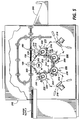
transfer apparatus 200 according to the present invention is illustrated and includes a continuous transfer belt, designated generally byreference numeral 202. As shown, thetransfer belt 202 is trained for movement about a series of rollers R1, R2, ...Rn by a first drive such as MB.Continuous transfer belt 202 is moved as such in the direction ofarrow 203, and is biased to a second electrical potential P2 according to the present invention. Four latent imaging units, indicated generally by thereference numerals continuous transfer belt 202. Each latent imaging unit is substantially identical to one another. The only distinctions between the latent imaging units is their geometric position and the color of the liquid developer material employed therein. For example,latent imaging unit 204 uses a black colored liquid developer material whileunits units only unit 210 will be described here in detail. - At
unit 210, adrum 212 having aphotoconductive surface 213 deposited on a conductive substrate rotates in the direction ofarrow 214. Preferably, thephotoconductive surface 213 has uncharged, first potential P1, and is made from a selenium alloy with the conductive substrate being made from an electrically grounded aluminum alloy. Other suitable photoconductive surfaces and conductive substrates may also be employed.Drum 212 rotates in the direction ofarrow 214 to advance successive portions of the photoconductive surface through the various processing stations disposed about its path of movement thereof. - Initially, a portion of the photoconductive surface of
drum 212 passes beneath acorona generating device 216.Corona generating device 216 charges the photoconductive surface ofdrum 212 to a relatively high, substantially uniform third electrical potential P3. - Next, the charged portion of the photoconductive surface is advanced through imaging station. At the imaging station, an imaging unit, indicated generally by the
reference numeral 218, records an electrostatic latent image on the photoconductive surface ofdrum 212.Imaging unit 218, for example, includes a raster output scanner. The raster output scanner lays out the electrostatic latent image in a series of horizontal scan lines with each line having a specified number of pixels per inch. Preferably, the raster output scanner employs a laser which generates a beam of light rays that are modulated by rotating polygon mirror blocks or solid state image modulator bars. Alternatively, the raster output scanner may use light emitting diode array write bars. In this way, an electrostatic latent image is recorded on the photoconductive surface ofdrum 212. - In accordance with the present invention, the
drum 212 of eachimaging unit transfer belt 202. As shown, the multicolorliquid apparatus 200 includes a device 230 (to be described below FIG. 6) for introducing the various colors ofliquid toner 132 that is charged to a potential P4 or P5 as above, into the process nip 220 of each imaging unit. Thedevice 230, for example, can be a liquid extruder as disclosed in US-A-5,355,201, relevant parts of which are incorporated here by reference. - Referring briefly to FIG. 6, the
liquid extruder 230 includes afirst member 232 and asecond member 234. An open-endeddistribution channel 236 is formed infirst member 232. Anotherdistribution channel 238 extends in a direction substantially transverse to channel 236 which is located along the longitudinal axis of therotatable drum 212. A first portion of thedistribution channel 236 is connected to a supply of liquid developer material. A plurality of substantially equally spaceddistribution channels 238 intersect with branches ofchannel 236.Distribution channels 238 receive liquid developer material fromchannel 236 and guide the liquid developer material tolip 242. The angle of ink distribution to channel 238 ensure that the liquid developer material coats thelip 242 with a film having a straight leading and trailing edge. The angle of the incline of the channel and the cross-sectional diameter ensures substantially uniform distribution of liquid developer material along thelip 242.Lip 242 is a surface ofsecond member 234 which is substantially parallel to the longitudinal axis ofdrum 212 and defines a gap therebetween. The gap betweenlip 242 and drum 212 is less than the gap between the surface offirst member 232 anddrum 212.Lip 242 is used to apply liquid developer material of a substantially uniform thickness to the entire image frame including image and background areas of the latent image recorded onphotoconductive surface 213 ofdrum 212. A metering pump is used to pump a requisite amount of liquid developer material for each electrostatic latent image from the supply of liquid developer material toliquid extruder 230. - As such, the
device 230 is a source of charged liquid toner or ink, just as was thesource 134 FIG. 2. In a CAD process, the chargedliquid toner 132 will have a potential P5 and a polarity that are relatively the same as those of the first, uncharged, electrical potential P1 ofsurface 213 ofdrum 212. As such, it is relatively opposite to the third, charged electrical potential P3 ofsurface 213. Thedevice 230 thus applies a uniform coating of liquid toner onto the entire imaged frame ofsurface 213, at a point upstream of the process nip 220, when considered relative to movement of thedrum 212. The layer of charged liquid toner is brought into thenip 220 on the surface ofdrum 212, where it is sandwiched according to the present invention as described above between thedrum 212 and thesurface transfer belt 202, and is moved through the process nip 220, in the presence of electrical fields set up due to the various electrical potentials P1 to P4 or P5. - Referring again to FIG. 5, simultaneous development and transfer of toner image areas and background areas will occur within the
nip 220 ofimaging unit 210. Accordingly, segmented portions of cyan color liquid toner, in the image areas of the latent image, will each comprise a first layer SL of toner solids that is in contact with thetransfer belt 202, and a separate second layer LL, mainly of clear carrier liquid that is in contact with thecharge bearing surface 213 ofdrum 212. On the other hand, segmented portions of cyan liquid toner in the background areas of the latent image will each comprise a separate second layer LL of mainly clear carrier liquid that is in contact with thetransfer belt 202, and a first layer SL of toner solids in contact withcharge bearing surface 213. - Upon separation of the
surface 213 ofdrum 212 from the surface of thetransfer belt 202 at an exit point of thenip 220, each of the segmented portions of sandwiched cyan liquid toner (comprising a solids layer SL, and a liquid layer LL) will "split"at the liquid layer LL thereof from the surface contacting such liquid layer LL. As such, desired cyan color toner image areas each having a toner solids layer SL contacting the surface of thetransfer belt 202 and essentially clear liquid layer LL contacting thesurface 213, will split at thesurface 213 ofdrum 212. Such splitting leaves essentially only clear liquid layers on thesurface 213 in such areas. The toner solids layers SL thereof which make up the desired toner image, will thus separate from thesurface 213, and remain on thetransfer belt 202. This in effect has been achieved within thenip 220 in a simultaneous develop-and-transfer manner. - On the other hand, the split of the solids and liquid layers in the background areas of the latent image will be quite opposite to the split in the image areas as described above. As such, the splits in the background areas will occur at the clear liquid lyers LL on the
transfer belt 202, thus leaving essentially clear liquid on thebelt 202 in these areas. The toner solids layer SL thereof will thus remain as a cyan color toner pattern on thesurface 213 ofdrum 212 for subsequent removal by acleaning device 250. - In accordance with the multicolor embodiment of the present invention, the
extruder device 230 of theimaging unit 210 thus uses charged cyan colored liquid developer material, and a cyan toner image is simultaneously developed and transferred onto thebelt 202.Latent imaging units transfer belt 202 may be more than is desirable for subsequent immediate operations. As such, aroller 252, whose surface moves in a direction opposite to the direction of movement of thetransfer belt 202, and that is spaced from the surface ofbelt 202,may be provided for shearing excessive liquid from the developed image without disturbing the image. - After the developed cyan liquid toner image is simultaneously developed and transferred to
continuous transfer belt 202 at theimaging unit 210 as above,continuous transfer belt 202 moves such image to thenext imaging unit 208. In general, at the next imaging unit, a liquid toner image of a different color is similarly formed according to the present invention (and in superimposed registration as is well known) onto thetransfer belt 202. Accordingly, a magenta liquid toner image is formed on thebelt 202 atimaging unit 208 and in superimposed registration with the cyan liquid toner image previously formed thereon. Next, a yellow liquid image is similarly formed atimaging unit 206, and finally, the black liquid toner image is similarly formed atimaging unit 204. - After all of the liquid images have been formed into a multicolor liquid toner image on
continuous transfer belt 202 as above, in accordance with the method of the present invention, the multicolor liquid toner image is subsequently transferred at a transfer nip 260 to a sheet of support material, e.g. a sheet ofcopy paper 154. As shown, transfer nip 260 is formed in part by thecontinuous transfer belt 202 and by a back up roller 262. As further illustrated, the transfer nip 260 may include aheating device 160 for simultaneously heating and fixing the transferred liquid toner image onto thecopy sheet 154. After such fixing or fusing, thecopy sheet 154 is advanced to catchtray 266 for subsequent removal from the printing machine by the operator. - Residual liquid developer material remaining or adhering to the
continuous transfer belt 202 after transfer is removed for example at a cleaning station 270. Cleaning station 270 may include a cleaning roller, formed of any appropriate synthetic resin driven in a direction opposite to the direction of movement ofcontinuous transfer belt 202 so as to scrub the surface thereof clean. To assist in this action, liquid carrier may be fed through a pipe onto the surface of the cleaning roller. A wiper blade may also be used to complete the cleaning of the surface ofbelt 202 in preparation for receiving another multicolor as above. - As can be seen, a method and apparatus have been disclosed for simultaneously developing and transferring liquid toner images to an intermediate receiver member. This is accomplished by sandwiching liquid ink or toner in a nip formed by a photoreceptor carrying the electrostatic latent form of the image and by a synchronous speed conductive or dielectric overcoated conductor, intermediate belt which is biased at a voltage intermediate between the image potential and the background voltage of the photoreceptor. With appropriate biasing and image potential, it is possible to so form positive or negative images (using positive or negatively charged liquid toners). Preferably, the images must be so formed on the belt using a convex shaped photoreceptor. The toner image formed on the belt would require blotting and for color products the process would have to be repeated several times.
- The process of the present invention can be referred to as a transdevelopment process, since it involves a simultaneous development and transfer that results in toner images being created directly on an intermediate member, not on the photoreceptor with subsequent transfer as is conventional. Such simultaneous development and transfer is enabled by creation of a development nip consisting of a photoreceptor and the transfer belt moving at the same speed and in the same direction. Liquid toner at approximately 2% - 25% solids is introduced into the nip. The photoreceptor normally biased at a first potential, is charged to a voltage or potential P3 (V-high), and is discharged in image areas to the first potential voltage P1 (V-low). The transfer belt which can be conductive or dielectric coated is at another potential or voltage P2 (V-mid) so that P2 lies between P3 (V-high) and P1 (V-low). The electric fields as such in conjunction with the charge on the toner, will force the charged toner in the process nip against the transfer belt in image areas. On the other hand, it will force the charged toner against the photoreceptor in background areas. In the nip, the sandwiched toner forms solids layers of more concentrated toner on top or below layers of clear carrier liquid. At the exit of the nip, the sandwiched toner will split in the regions of lowest viscosity, i.e., in the layers of clear carrier liquid. In multicolor image on image processing, a first toner image is thus produced directly on the transfer belt, and can then be conditioned on the belt before the next and subsequent toner images are similarly transdeveloped onto the first toner image.
- The advantages of the transdevelopment process of the present invention include the fact that with a long process nip created by a large wrap of the belt over the photoreceptor (drum or belt) high viscosity inks can be transdeveloped directly onto the belt. Another advantage is that higher solids concentration inks can be used since toner will only be required to migrate a very short distance in a direction normal to the photoreceptor and belt surfaces. The ink layer will move through the nip with uniform velocity equal to the photoreceptor and belt velocity. The gap in the nip can be controlled by proper tension on the belt.
- The development process of the present invention is similar to that observed in parallel plate electrode development, including some ink visualization cells. In parallel plate electrode development experiments, highly concentrated toner layers were created by applied electric fields. Areas of clear carrier fluid resulting from toner migration were observed. A further important observation was that if the electrodes were separated apart while maintaining an applied voltage thereon, the sandwiched toner split occurred in the clear liquid layers leaving one electrode with the toner layer and the other with half of the clear liquid layer.
- This same film splitting effect will occur at the exit of the transdevelopment nip according to the present invention, thus leaving toner images with clean background on the transfer belt. A further advantage is that since shearing forces are small in a system with uniform velocity, disturbance of the toner layer due to high shearing forces will not occur in a transdevelopment according to the present invention.
Claims (11)
- An apparatus (100) for simultaneously developing and transferring a liquid toner image, the apparatus including a movable photoreceptive member (110) having a charge bearing surface (112) at a first electrical potential (P1); and image forming means for forming a latent image electrostatically on said charge bearing surface (112), said latent image forming means including a charging device (126) for uniformly placing a layer of charge on said charge bearing surface (112);characterised by a movable intermediate transfer member (116) biased to a second electrical potential (P2), said intermediate transfer member (116) forming a process nip (120) with said charge bearing surface (112); said image forming means adapted to form the latent image with image areas each having a third electrical potential (P3), and background areas each having said first electrical potential (P1) of said charge bearing surface (112); andfeed means for introducing charged liquid toner consisting of toner solids and a carrier liquid into said process nip (120), said charged liquid toner having a fourth electrical potential (P5), and said charged liquid toner being sandwiched, within an electrical field formed within said nip (120) by said first (P1), said second (P2), and said third (P3) electrical potentials, and between said charge bearing surface (112) and said intermediate transfer member (116), so as to simultaneously develop and transfer a toner image of said latent image onto said intermediate transfer member (116).
- An apparatus as claimed in claim 1, wherein said charge bearing surface (112) of said photoreceptor has a convex path within said process nip (120).
- An apparatus as claimed in claim 1 or claim 2, wherein within said process nip (120), said intermediate transfer member (116) is spaced a distance of 15 to 50 micrometers from said charge bearing surface (112).
- An apparatus as claimed in any one of claims 1 to 3, wherein said feed means for introducing charged liquid toner into said process nip (120) includes means for applying a uniform coating of charged liquid toner onto a portion of the surface of said intermediate transfer member (116) and at a point upstream of said process nip, relative to movement of said intermediate transfer member (116).
- An apparatus as claimed in any one of claims 1 to 4, wherein said charged liquid toner sandwiched within said process nip in said electrical field forms in image areas of said latent image, a toner solids layer on said intermediate transfer member, and a carrier liquid layer in said same image areas on said charge bearing surface; or wherein said charged liquid toner sandwiched within said process nip in said electrical field forms in background areas of said latent image, a toner solids layer on said charge bearing surface, and a carrier liquid layer in said same background areas on said intermediate transfer member.
- An apparatus as claimed in any one of claims 1 to 5, wherein at least one of said photoreceptor and said intermediate transfer member (116) is flexible.
- An apparatus as claimed in any one of claims 1 to 6, wherein said liquid toner comprises a carrier liquid and a 2% - 25% toner solids content by volume.
- An apparatus as claimed in any one of claims 1 to 7, wherein said liquid toner sandwiched in said process nip (120) within said electrical field comprises segmented portions, each portion of said segmented portions including a first layer of toner solids and a separate second layer of carrier liquid.
- An apparatus for simultaneously developing and transferring a liquid toner image, the apparatus including a movable imaging member (110) including a charge bearing surface (112); charging means for applying a uniform layer of charge on said charge bearing surface, said layer of charge having a first electrical potential; and means for imagewise dissipating charge from selected portions on said charge portions to form a latent image electrostatically on said charge bearing surface, said dissipated portions having a second electrical potential; characterised by a movable intermediate transfer member (116) forming a process nip (120) with said movable imaging member (110), said intermediate transfer member (116) being biased to a third electrical potential; means for introducing charged liquid toner into said process nip, said charged liquid toner having a forth potential; and drive means for moving said movable imaging member (110) and said movable intermediate transfer member (116) through said process nip, said imaging member and said intermediate transfer member sandwiching a layer of liquid toner through said process nip (120), and said sandwiched liquid toner simultaneously developing and transferring said latent image onto said intermediate transfer member under an electric field created within said process nip by said first, second, third and fourth electrical potentials.
- A multicolor liquid printing apparatus comprising:(a) a main assembly including a movable intermediate transfer member, biased to a first electrical potential, for receiving toner images, and means for moving said intermediate transfer member along a path of movement at a first velocity;(b) a plurality of latent image forming units mounted along a path of movement of said intermediate transfer member, each latent image forming unit including:(i) a movable photoreceptor including a charge bearing surface having an uncharged, second electrical potential;(ii) charging means for applying a uniform layer of charge having a third electrical potential onto said charge bearing surface;(iii) means for imagewise dissipating charge from selected portions of said uniformly charged surface to form a latent image electrostatically on said charge bearing surface, said selected charge dissipated portions having said uncharged, second electrical potential;(c) a plurality of process nips formed at each imaging unit by said intermediate transfer member and the photoreceptor of the each imaging unit; and(d) feed means for introducing charged liquid toner of a different color into each process nip of said plurality of process nips, said charged liquid toner consisting of a carrier liquid and charged toner solids having a fourth electrical potential, so as to simultaneously develop and transfer, within each said process nip, a toner image of image areas of said latent image onto said intermediate transfer member, and a toner pattern of background areas of said latent image onto each said photoreceptor of each the imaging units.
- A method for simultaneously developing and transferring a liquid toner image, including moving a photoreceptive member (110) including a charge bearing surface (112) having a first electrical potential (P1), applying a uniform layer of charge having a second electrical potential (P3) onto the charge bearing surface (112), and imagewise dissipating charge from selected portions on the charge bearing surface (112) to form a latent image electrostatically, such that the charge-dissipated portions of the charge bearing surface (112) have the first electrical potential of the charge bearing surface (112); characterised by moving an intermediate transfer member (116) biased to a third electrical potential (P2) that lies between said first and second potentials, into a nip forming relationship with the moving imaging member to form a process nip, introducing charged liquid toner, having a fourth electrical potential, into the process nip (120), such that liquid toner sandwiched within the nip (120) simultaneously develops image portions of the latent image onto the intermediate transfer member (116), and background portions of the latent image onto the charge bearing surface (112) of the photoreceptor (110).
Applications Claiming Priority (2)
| Application Number | Priority Date | Filing Date | Title |
|---|---|---|---|
| US08/431,803 US5619313A (en) | 1995-05-01 | 1995-05-01 | Method and apparatus for liquid image development and transfer |
| US431803 | 1999-11-01 |
Publications (2)
| Publication Number | Publication Date |
|---|---|
| EP0741340A1 true EP0741340A1 (en) | 1996-11-06 |
| EP0741340B1 EP0741340B1 (en) | 2001-10-24 |
Family
ID=23713486
Family Applications (1)
| Application Number | Title | Priority Date | Filing Date |
|---|---|---|---|
| EP96303092A Expired - Lifetime EP0741340B1 (en) | 1995-05-01 | 1996-05-01 | Method and apparatus for liquid image development and transfer |
Country Status (4)
| Country | Link |
|---|---|
| US (1) | US5619313A (en) |
| EP (1) | EP0741340B1 (en) |
| JP (1) | JPH08305173A (en) |
| DE (1) | DE69616142T2 (en) |
Cited By (1)
| Publication number | Priority date | Publication date | Assignee | Title |
|---|---|---|---|---|
| EP1103867A1 (en) * | 1999-11-29 | 2001-05-30 | Xerox Corporation | Multicolor image-on-image forming machine using air breakdown charge and development (abcd) process |
Families Citing this family (29)
| Publication number | Priority date | Publication date | Assignee | Title |
|---|---|---|---|---|
| US5826147A (en) * | 1997-06-27 | 1998-10-20 | Xerox Corporation | Electrostatic latent image development |
| US5937243A (en) * | 1997-06-27 | 1999-08-10 | Xerox Corporation | Image-wise toner layer charging via air breakdown for image development |
| US5966570A (en) * | 1998-01-08 | 1999-10-12 | Xerox Corporation | Image-wise toner layer charging for image development |
| US5991582A (en) * | 1998-11-02 | 1999-11-23 | Xerox Corporation | Method and apparatus for developing high quality images in a liquid immersion development machine |
| US6006061A (en) * | 1998-11-02 | 1999-12-21 | Xerox Corporation | Method and apparatus for forming high quality images in an electrostatic printing machine |
| US6020099A (en) * | 1998-11-02 | 2000-02-01 | Xerox Corporation | Method and apparatus for forming and refining toner images in an electrostatic printing machine |
| US6052550A (en) * | 1998-11-13 | 2000-04-18 | Xerox Corporation | Image separator having conformable layer for contact electrostatic printing |
| US5991577A (en) * | 1998-11-23 | 1999-11-23 | Xerox Corporation | Air breakdown charge and development image forming method and apparatus using image area centered patches of toner |
| US5937248A (en) * | 1998-11-23 | 1999-08-10 | Xerox Corporation | Contact electrostatic printing image forming method and apparatus using image area centered patch of tonerpatches of toner |
| US5991578A (en) * | 1998-11-23 | 1999-11-23 | Xerox Corporation | Image forming reverse charge printing method and apparatus using image area centered patches of toner |
| US6117602A (en) * | 1999-01-19 | 2000-09-12 | Xerox Corporation | Electrostatic printing method and apparatus having enhanced image resolution characteristics |
| US6049683A (en) * | 1999-01-19 | 2000-04-11 | Xerox Corporation | Electrostatic printing method and apparatus having enhanced custom color characteristics |
| US5987283A (en) * | 1999-01-19 | 1999-11-16 | Xerox Corporation | Apparatus and method for developing an electrostatic latent image directly from an imaging member to a final substrate |
| US6009294A (en) * | 1999-01-19 | 1999-12-28 | Xerox Corporation | Addressable toner applicator and method and apparatus for enhancing custom color characteristics in a contact electrostatic printing apparatus |
| US6367909B1 (en) | 1999-11-23 | 2002-04-09 | Xerox Corporation | Method and apparatus for reducing drop placement error in printers |
| US6289191B1 (en) * | 1999-11-26 | 2001-09-11 | Xerox Corporation | Single pass, multicolor contact electrostatic printing system |
| US6181901B1 (en) | 1999-11-29 | 2001-01-30 | Xerox Corporation | Multicolor image-on-image forming machine using reverse charge printing (RCP) process |
| US6122471A (en) * | 1999-12-08 | 2000-09-19 | Xerox Corporation | Method and apparatus for delivery of high solids content toner cake in a contact electrostatic printing system |
| US6256468B1 (en) | 2000-03-13 | 2001-07-03 | Xerox Corporation | Toner cake delivery system having a carrier fluid separation surface |
| US6219501B1 (en) | 2000-03-28 | 2001-04-17 | Xerox Corporation | Method and apparatus for toner cake delivery |
| US6438332B2 (en) | 2000-03-28 | 2002-08-20 | Xerox Corporation | Method and apparatus for toner cake delivery |
| US6311035B1 (en) | 2000-06-16 | 2001-10-30 | Xerox Corporation | Reprographic system operable for direct transfer of a developed image from an imaging member to a copy substrate |
| US7006244B2 (en) | 2000-12-06 | 2006-02-28 | Xerox Corporation | Image rendering method and system using negative signals |
| US6434352B1 (en) | 2000-12-11 | 2002-08-13 | Xerox Corporation | Liquid ink development (LID) machine having a fluid film thickness control apparatus |
| US6440629B1 (en) | 2001-02-06 | 2002-08-27 | Xerox Corporation | Imaging apparatus |
| US6458500B1 (en) | 2001-02-06 | 2002-10-01 | Xerox Corporation | Imaging apparatus |
| JP4214356B2 (en) * | 2001-09-20 | 2009-01-28 | 富士ゼロックス株式会社 | Image forming apparatus |
| US6621998B2 (en) | 2001-12-14 | 2003-09-16 | Xerox Corporation | Method and apparatus for formation and development of high solids content toner cake in an electrostatic printing system |
| US7046947B1 (en) | 2004-12-13 | 2006-05-16 | Xerox Corporation | Free sheet color digital output terminal architectures |
Citations (4)
| Publication number | Priority date | Publication date | Assignee | Title |
|---|---|---|---|---|
| US5150161A (en) * | 1991-04-09 | 1992-09-22 | Olin Corporation | Color printing apparatus and process using first and second transfer surfaces |
| US5233396A (en) * | 1991-12-09 | 1993-08-03 | Xerox Corporation | Intermediate transfer member having a low surface energy compliant structure and method of using same |
| US5243392A (en) * | 1990-04-23 | 1993-09-07 | Xerox Corporation | Imaging apparatus and process with intermediate transfer element |
| EP0584893A2 (en) * | 1989-08-14 | 1994-03-02 | Indigo N.V. | Image transfer apparatus and method |
Family Cites Families (9)
| Publication number | Priority date | Publication date | Assignee | Title |
|---|---|---|---|---|
| CA1204148A (en) * | 1982-05-26 | 1986-05-06 | Petrus R. Nelen | Apparatus for transferring xerographic images |
| US4707112A (en) * | 1986-05-16 | 1987-11-17 | Xerox Corporation | Liquid development system |
| US4912514A (en) * | 1987-05-19 | 1990-03-27 | Citizen Watch Co., Ltd. | Electrophotographic printer |
| US4935788A (en) * | 1988-06-16 | 1990-06-19 | Xerox Corporation | Multicolor printing system |
| US5028964A (en) * | 1989-02-06 | 1991-07-02 | Spectrum Sciences B.V. | Imaging system with rigidizer and intermediate transfer member |
| US5012289A (en) * | 1989-08-11 | 1991-04-30 | International Business Machines Corporation | Toner metering apparatus |
| US5387760A (en) * | 1990-10-19 | 1995-02-07 | Seiko Epson Corporation | Wet recording apparatus for developing electrostatic latent image |
| US5158846A (en) * | 1990-10-29 | 1992-10-27 | Olin Corporation | Electrostatic color printing system utilizing an image transfer belt |
| US5355201A (en) * | 1993-07-21 | 1994-10-11 | Xerox Corporation | Liquid development system |
-
1995
- 1995-05-01 US US08/431,803 patent/US5619313A/en not_active Expired - Fee Related
-
1996
- 1996-04-23 JP JP8101174A patent/JPH08305173A/en not_active Withdrawn
- 1996-05-01 DE DE69616142T patent/DE69616142T2/en not_active Expired - Fee Related
- 1996-05-01 EP EP96303092A patent/EP0741340B1/en not_active Expired - Lifetime
Patent Citations (4)
| Publication number | Priority date | Publication date | Assignee | Title |
|---|---|---|---|---|
| EP0584893A2 (en) * | 1989-08-14 | 1994-03-02 | Indigo N.V. | Image transfer apparatus and method |
| US5243392A (en) * | 1990-04-23 | 1993-09-07 | Xerox Corporation | Imaging apparatus and process with intermediate transfer element |
| US5150161A (en) * | 1991-04-09 | 1992-09-22 | Olin Corporation | Color printing apparatus and process using first and second transfer surfaces |
| US5233396A (en) * | 1991-12-09 | 1993-08-03 | Xerox Corporation | Intermediate transfer member having a low surface energy compliant structure and method of using same |
Cited By (1)
| Publication number | Priority date | Publication date | Assignee | Title |
|---|---|---|---|---|
| EP1103867A1 (en) * | 1999-11-29 | 2001-05-30 | Xerox Corporation | Multicolor image-on-image forming machine using air breakdown charge and development (abcd) process |
Also Published As
| Publication number | Publication date |
|---|---|
| JPH08305173A (en) | 1996-11-22 |
| DE69616142T2 (en) | 2002-06-06 |
| US5619313A (en) | 1997-04-08 |
| EP0741340B1 (en) | 2001-10-24 |
| DE69616142D1 (en) | 2001-11-29 |
Similar Documents
| Publication | Publication Date | Title |
|---|---|---|
| EP0741340B1 (en) | Method and apparatus for liquid image development and transfer | |
| US5585900A (en) | Developer for liquid toner imager | |
| US4935788A (en) | Multicolor printing system | |
| US4810604A (en) | Combination xerographic and direct electrostatic printing apparatus for highlight color imaging | |
| US5749032A (en) | Color imaging system | |
| US5255058A (en) | Liquid developer imaging system using a spaced developing roller and a toner background removal surface | |
| US5231454A (en) | Charge director replenishment system and method for a liquid toner developing apparatus | |
| CA2090025C (en) | Liquid developer system | |
| US5023665A (en) | Excess liquid carrier removal apparatus | |
| EP0635766B1 (en) | A liquid development system | |
| US5452063A (en) | Intermediate transfer with high relative humidity papers | |
| US5613174A (en) | Imaging device with positive air pressure and electrostatic precipitator | |
| US7031649B2 (en) | Image forming apparatus | |
| US5655192A (en) | Method and apparatus for compaction of a liquid ink developed image in a liquid ink type electrostatographic system | |
| EP0340996B1 (en) | Tri-level, highlight color imaging using ionography | |
| US5848337A (en) | Electrical biasing scheme for preventing overplating in an image-on-image electrostatographic printing system | |
| US6185399B1 (en) | Multicolor image-on-image forming machine using air breakdown charge and development (ABCD) Process | |
| US5940665A (en) | Liquid immersion development machine having a multiple zone image development and conditioning apparatus | |
| US5826149A (en) | Developing device employing a liquid developer and picture forming device having such developing device | |
| US6289191B1 (en) | Single pass, multicolor contact electrostatic printing system | |
| US5708936A (en) | Hydrodynamically stable coating flow applicator | |
| US5077172A (en) | Carrier web transfer device and method for electrophotographic printing press | |
| US5420672A (en) | Concept for prevention of scavengeless nip wire contamination with toner | |
| US5576817A (en) | Dual zone development for liquid developers | |
| US20040114963A1 (en) | System and method for latent image development |
Legal Events
| Date | Code | Title | Description |
|---|---|---|---|
| PUAI | Public reference made under article 153(3) epc to a published international application that has entered the european phase |
Free format text: ORIGINAL CODE: 0009012 |
|
| AK | Designated contracting states |
Kind code of ref document: A1 Designated state(s): DE FR GB |
|
| 17P | Request for examination filed |
Effective date: 19970506 |
|
| 17Q | First examination report despatched |
Effective date: 19991210 |
|
| GRAG | Despatch of communication of intention to grant |
Free format text: ORIGINAL CODE: EPIDOS AGRA |
|
| GRAG | Despatch of communication of intention to grant |
Free format text: ORIGINAL CODE: EPIDOS AGRA |
|
| GRAH | Despatch of communication of intention to grant a patent |
Free format text: ORIGINAL CODE: EPIDOS IGRA |
|
| GRAH | Despatch of communication of intention to grant a patent |
Free format text: ORIGINAL CODE: EPIDOS IGRA |
|
| GRAA | (expected) grant |
Free format text: ORIGINAL CODE: 0009210 |
|
| AK | Designated contracting states |
Kind code of ref document: B1 Designated state(s): DE FR GB |
|
| REF | Corresponds to: |
Ref document number: 69616142 Country of ref document: DE Date of ref document: 20011129 |
|
| REG | Reference to a national code |
Ref country code: GB Ref legal event code: IF02 |
|
| ET | Fr: translation filed | ||
| PLBE | No opposition filed within time limit |
Free format text: ORIGINAL CODE: 0009261 |
|
| STAA | Information on the status of an ep patent application or granted ep patent |
Free format text: STATUS: NO OPPOSITION FILED WITHIN TIME LIMIT |
|
| 26N | No opposition filed | ||
| PGFP | Annual fee paid to national office [announced via postgrant information from national office to epo] |
Ref country code: GB Payment date: 20040428 Year of fee payment: 9 |
|
| PGFP | Annual fee paid to national office [announced via postgrant information from national office to epo] |
Ref country code: FR Payment date: 20040510 Year of fee payment: 9 |
|
| PGFP | Annual fee paid to national office [announced via postgrant information from national office to epo] |
Ref country code: DE Payment date: 20040513 Year of fee payment: 9 |
|
| PG25 | Lapsed in a contracting state [announced via postgrant information from national office to epo] |
Ref country code: GB Free format text: LAPSE BECAUSE OF NON-PAYMENT OF DUE FEES Effective date: 20050501 |
|
| PG25 | Lapsed in a contracting state [announced via postgrant information from national office to epo] |
Ref country code: DE Free format text: LAPSE BECAUSE OF NON-PAYMENT OF DUE FEES Effective date: 20051201 |
|
| GBPC | Gb: european patent ceased through non-payment of renewal fee |
Effective date: 20050501 |
|
| PG25 | Lapsed in a contracting state [announced via postgrant information from national office to epo] |
Ref country code: FR Free format text: LAPSE BECAUSE OF NON-PAYMENT OF DUE FEES Effective date: 20060131 |
|
| REG | Reference to a national code |
Ref country code: FR Ref legal event code: ST Effective date: 20060131 |