EP0741268B1 - Liner panel for a gas turbine combustor wall - Google Patents
Liner panel for a gas turbine combustor wall Download PDFInfo
- Publication number
- EP0741268B1 EP0741268B1 EP96302768A EP96302768A EP0741268B1 EP 0741268 B1 EP0741268 B1 EP 0741268B1 EP 96302768 A EP96302768 A EP 96302768A EP 96302768 A EP96302768 A EP 96302768A EP 0741268 B1 EP0741268 B1 EP 0741268B1
- Authority
- EP
- European Patent Office
- Prior art keywords
- trailing
- panel
- segment
- wall
- combustor
- Prior art date
- Legal status (The legal status is an assumption and is not a legal conclusion. Google has not performed a legal analysis and makes no representation as to the accuracy of the status listed.)
- Expired - Lifetime
Links
- 239000002826 coolant Substances 0.000 claims description 8
- 239000012809 cooling fluid Substances 0.000 claims description 2
- 230000002452 interceptive effect Effects 0.000 claims description 2
- 238000007789 sealing Methods 0.000 claims 1
- 238000001816 cooling Methods 0.000 description 19
- 238000010276 construction Methods 0.000 description 5
- 238000005266 casting Methods 0.000 description 4
- 238000004519 manufacturing process Methods 0.000 description 3
- 125000006850 spacer group Chemical group 0.000 description 3
- 230000035882 stress Effects 0.000 description 3
- 230000008646 thermal stress Effects 0.000 description 2
- 238000013459 approach Methods 0.000 description 1
- 238000002485 combustion reaction Methods 0.000 description 1
- 238000012423 maintenance Methods 0.000 description 1
- 239000000463 material Substances 0.000 description 1
- 230000007704 transition Effects 0.000 description 1
Images
Classifications
-
- F—MECHANICAL ENGINEERING; LIGHTING; HEATING; WEAPONS; BLASTING
- F23—COMBUSTION APPARATUS; COMBUSTION PROCESSES
- F23R—GENERATING COMBUSTION PRODUCTS OF HIGH PRESSURE OR HIGH VELOCITY, e.g. GAS-TURBINE COMBUSTION CHAMBERS
- F23R3/00—Continuous combustion chambers using liquid or gaseous fuel
- F23R3/002—Wall structures
Landscapes
- Engineering & Computer Science (AREA)
- Chemical & Material Sciences (AREA)
- Combustion & Propulsion (AREA)
- Mechanical Engineering (AREA)
- General Engineering & Computer Science (AREA)
- Turbine Rotor Nozzle Sealing (AREA)
- Gas Burners (AREA)
Description
- This invention relates to combustors for gas turbine engines in general, and to double wall gas turbine combustors in particular.
- Gas turbine engine combustors are generally subject to high thermal loads for prolonged periods of time. To alleviate the accompanying thermal stresses, it is known to cool the walls of the combustor. Cooling helps to increase the usable life of the combustor components and therefore increase the reliability of the overall engine.
- In one cooling embodiment, a combustor may include a plurality of overlapping wall segments successively arranged where the forward edge of each wall segment is positioned to catch cooling air passing by the outside of the combustor. The forward edge diverts cooling air over the internal side, or "hot side", of the wall segment and thereby provides film cooling for the internal side of the segment. A disadvantage of this cooling arrangement is that the necessary hardware includes a multiplicity of parts. A person of skill in the art will recognise that there is considerable value in minimizing the number of parts within a gas turbine engine, not only from a cost perspective, but also for safety and reliability reasons. Specifically, internal components such as turbines and compressors can be susceptible to damage from foreign objects carried within the air flow through the engine.
- A further disadvantage of the above described cooling arrangement is the overall weight which accompanies the multiplicity of parts. A person of skill in the art will recognise that weight is a critical design parameter of every component in a gas turbine engine, and that there is considerable advantage to minimising weight wherever possible.
- In other cooling arrangements, a twin wall configuration has been adopted where an inner wall and an outer wall are provided separated by a specific distance. Cooling air passes through holes in the outer wall and then again through holes in the inner wall, and finally into the combustion chamber. An advantage of a twin wall arrangement compared to an overlapping wall segment arrangement is that an assembled twin wall arrangement is structurally stronger. A disadvantage to the twin wall arrangement, however, is that thermal growth must be accounted for closely. Specifically, the thermal load in a combustor tends to be non-uniform. As a result, different parts of the combustor will experience different amounts of thermal growth, stress, and strain. If the combustor design does not account for non-uniform thermal growth, stress, and strain, then the usable life of the combustor may be negatively affected.
- What is needed, therefore, is a combustor for a gas turbine engine which can accommodate a non-uniform thermal load, one that minimises weight, and one that has a minimal number of parts.
- WO 92/16798 discloses a combustor having the features of the preamble of claim 1 and a liner segment having the features of the preamble of claim 4.
- The combustor of the present invention is characterised over the disclosure of WO 92/16798 by the features of the characterising portion of claim 1, and the liner of the invention characterised over the disclosure of WO 92/16798 by the features of the characterising portion of claim 4.
- The forward flange and/or trailing flange is/are provided to minimize disruptions in film cooling fluid paths between adjacent liner segments and thereby facilitate heat transfer.
- In a preferred embodiment of the present invention, a rib is provided extending out of the back surface of the panel for structural support.
- According to a further preferred feature of the present invention, the panel, walls, and mounting studs of each liner segment are integrally cast as a one piece unit.
- A preferred embodiment of the invention will now be described, by way of example only, with reference to the accompanying drawings, in which:
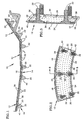
- FIG. 1 is a diagrammatic partial view of a combustor.
- FIG.2 is a perspective view of a liner segment.
- FIG. 3 is a cross-sectional view of the liner segment shown in FIG. 2.
- Referring to FIG. 1, a
combustor 10 for a gas turbine engine includes a plurality ofliner segments 12 and asupport shell 14. Thesupport shell 14 shown in FIG. 1 is a cross-sectional partial view of an annular shaped support shell. Alternatively, thecombustor 10 may be formed in other shapes, such as a cylindrical support shell (not shown). Thesupport shell 14 includes interior 16 and exterior 18 surfaces, a plurality ofmounting holes 20, and a plurality ofsecond coolant holes 22 extending through theinterior 16 and exterior 18 surfaces. - Referring to FIGS. 2 and 3, each
liner segment 12 includes apanel 24, aforward wall 26, atrailing wall 28, a pair ofside walls 30, and a plurality ofmounting studs 32. Thepanel 24 includes a face surface 34 (see FIG. 3) and aback surface 36, and a plurality offirst coolant holes 38 extending therethrough. Theforward wall 26 is positioned along aforward edge 40 of thepanel 24 and thetrailing wall 28 is positioned along atrailing edge 42 of thepanel 24. Theside walls 30 connect the forward 26 andtrailing walls 28. The forward 26, trailing 28, andside walls 30 extend out from the back surface 36 a particular distance. The plurality ofmounting studs 32 extend out from theback surface 36, and engage fastening means 44 (see FIG. 1). In the preferred embodiment, thestuds 32 are threaded and the fastening means 44 is a plurality oflocking nuts 45. -
- Referring to FIG. 2,
ribs 46 which extend out of theback surface 36 of thepanel 24 may be provided for additional structural support in some embodiments. The height of therib 46 away from theback surface 36 of thepanel 24 is less than that of thewalls - Referring to FIG. 3, a
forward flange 48 extends out from theforward wall 26. Theroot end 50 of thetrailing wall 28 and theforward flange 48 flange have arcuate profiles which facilitate flow transition betweenadjacent liner segments 12, and therefore minimize disruptions in the film cooling of theliner segments 12. Of course, an arcuate trailing flange extending from thetrailing wall 28 may equally be provided, such that extending flanges are provided at the front andtrailing edges - Each
liner segment 12 is formed by casting for several reasons. First, casting permits thepanel 24,walls studs 32 elements of eachsegment 12 to be integrally formed as a one piece unit, and thereby facilitateliner segment 12 manufacturing. Casting eachliner segment 12 also helps minimize the weight of eachliner segment 12. Specifically, integrally forming thesegment 12 elements in a one piece unit allows each element to draw from the mechanical strength of the adjacent elements. As a result, the individual elements can be less massive and the need for attachment medium between elements is obviated. Casting eachliner segment 12 also increases the uniformity ofliner segment 12 dimensions.Uniform liner segments 12 help the uniformity of the gaps betweenSegments 12 and the height ofsegments 12. Uniform gaps minimize the opportunity for binding betweenadjacent segments 12 and uniform segment heights make for a smoother aggregate flow surface. - Referring to FIG. 1, in the assembly of the
combustor 10, themounting studs 32 of eachliner segment 12 are received within themounting holes 20 in thesupport shell 14, such that thestuds 32 extend out on theexterior surface 18 of theshell 14.Locking nuts 45 are screwed on thestuds 32 thereby fixing theliner segment 12 on theinterior surface 16 of thesupport shell 14. Depending on the position of theliner segment 12 within thesupport shell 14 and the geometry of theliner segment 12, one ormore nuts 45 may be left less tight than other stud/nut combinations to encourageliner segment 12 thermal growth in a particular direction. In all cases, however, theliner segment 12 is tightened sufficiently to create a seal between theinterior surface 16 of thesupport shell 14 and thewalls segment liner 12. - Referring to FIG. 2, if the
liner segment 12 does includeribs 46 for further structural support, the height of therib 46 away from theback surface 36 of thepanel 24 is less than that of thewalls rib 46 and theinterior surface 16 of thesupport shell 14. The gap permits cooling air to enter underneath therib 46. - From the above description, it will be seen that an advantage of the present invention in its preferred embodiment is its ability to accommodate a non-uniform heat load. The liner segment and support shell construction permits thermal growth commensurate with whatever thermal load is present in a particular area of the combustor. Clearances between segments permit the thermal growth without the binding that contributes to mechanical stress and strain. The forward and trailing flanges of each segment further enhance the present invention's ability to accommodate non-uniform heat loads by minimizing disruptions in the film cooling between the spaced apart liner segments.
- The enhanced cooling of the support shell and liner segment construction is a further advantage. The support shell and liner construction minimises thermal gradients across the support shell and/or liner segments, and therefore thermal stress and strain within the combustor. The support shell and liner segment construction also minimises the volume of cooling airflow required to cool the combustor. A person of skill in the art will recognise that it is a distinct advantage to minimise the amount of cooling airflow devoted to cooling purposes.
- A still further advantage is that the wall and panel elements of the liner segments facilitate the uniform cooling of the combustor. Air passing through the support shell under a particular liner segment is directed up through the panel of that segment, cooling the panel as it passes through. If air entering under a particular segment were allowed to pass under adjacent liners it would not cool the panel of the segment it entered under as efficiently. Uniform cooling of the combustor is thereby promoted.
- A still further advantage is that a lightweight combustor is provided for a gas turbine engine. Each liner segment is cast to facilitate manufacture and to minimise weight. The elements of each liner segment, including the panel, and walls and mounting studs extending out from the panel, draw mechanical strength from being integrally formed with one another. The therefore greater structural integrity of each cast liner segment enables material normally required in the individual elements to be eliminated and the weight consequently reduced.
- A still further advantage is that a combustor for a gas turbine engine is provided with a minimal number of parts. Some combustor designs require a multiplicity of independent nuts and bolts to secure the walls of a twin wall combustor together. In addition, some twin wall combustor designs require a multiplicity of spacers be fixed between the walls to consistently space the walls apart from one another. A disadvantage of these approaches is that they increase the chance that a spacer, bolt, or nut can work free and cause foreign object damage downstream within the engine. This is particularly true if the object works free on the "hot side" of the combustor where it is more likely to be ingested into a downstream turbine or compressor. The liner segments of the preferred embodiment, on the other hand, have integrally formed studs for attachment and walls for spacing. The only additional hardware necessary is the means for fastening the studs on the exterior, or "cold side" of the combustor. The number of independent parts within the combustor, and therefore the number of parts that potentially could become free within the engine and cause damage is reduced.
- A still further advantage is that the combustor is inexpensive to manufacture and assemble. The twin wall configuration requires a plate-like support shell with holes for receiving the liner segment studs and holes for coolant, and a plurality of formed liner segments for attachment to the support shell. The support shell is a simple cost effective design which does not require attachment of spacers. Similarly, the liner segments are designed to be inexpensively cast and easily attached to the support shell.
- A still further advantage is that the support shell and liner segment construction facilitates maintenance. Individual liner segments may be replaced without having to disrupt adjacent liner segments.
- Although this invention has been shown and described with respect to the detailed embodiments thereof, it will be understood by those skilled in the art that various changes in form and detail thereof may be made without departing from the scope of the invention as defined by the following claims.
Claims (6)
- A combustor (10) for a gas turbine engine, comprising:a plurality of liner segments (12), each segment having:a panel (24), with a face surface (34) and a back surface (36), said panel having a plurality of first coolant holes (38);a forward wall (26), positioned along a forward edge (40) of said panel;a trailing wall (28), positioned along a trailing edge (42) of said panel;a pair of side walls (30), connecting said forward and trailing walls;wherein said forward, trailing, and side walls (26, 28,30) extend out from said back surface (36) a particular distance;a plurality of mounting studs (32), extending out from said back surface (36);a support shell (14), having an interior (16) and an exterior (18) surface, a plurality of mounting holes (20) for receiving said mounting studs (32) and a plurality of second coolant holes (22) extending through said support shell;and liner segment attachment means (44);wherein said liner segments (12) are attached to said support shell interior surface (16) by said mounting studs (32) extending through said mounting holes and co-operating with said liner segment attachment means (44), which means (44) act against said exterior surface (16) of said support shell (14);said walls (26,28,30) spacing said panel (24) a distance away from said support shell (14), and sealing the gap between said panel and said support shell thereby preventing air normally travelling in said second coolant holes (22) and out said first coolant holes (38) from escaping between said walls and said support shell, characterised in that each said liner segment (12) further comprises:a forward flange (48), extending out from said forward wall (26) ora trailing flange, extending out from said trailing wall (28), or both a said forward flange (48) and a said trailing flange and wherein the said flange or flanges include an arcuate shape to minimize disruptions in film cooling fluid paths between adjacent liner segments
- A combustor according to claim 1, wherein each said liner segment (12) further comprises:at least one rib (46), extending out of said back surface (36) a distance less than that of said walls (26,28,30), for structurally supporting said panel (24);whereby air may pass between said rib (46) and said support shell (14), to more uniformly cool said liner segment; andwherein space between said rib (46) and said support shell (14) prevents said rib (46) from interfering with said seal between said walls (26,28,30) and said support shell (14).
- A combustor according to any preceding claim,
wherein said panel (24), walls (26,28,30), rib (46), and mounting studs (32) of each liner segment (12) are integrally cast as a one piece unit. - A segment (12) for lining a combustor wall, comprising:a panel (24), with a face surface (34) and a back surface (36), said panel (24) having a plurality of coolant holes (38);a forward wall (26), positioned along a forward edge (40) of said panel (24);a trailing wall (28), positioned along a trailing edge (42) of said panel (24);a pair of side walls (30), connecting said forward and trailing walls (26,28);wherein said forward, trailing, and side walls (26, 28,30) extend out from said back surface (36) a particular distance; anda plurality of mounting studs (32), extending out from said back surface (36), the arrangement being such that, in use, the combustor wall may be lined by extending said mounting studs (32) of the segment (12) through the combustor wall for engagement with segment attachment means on the opposite side of the combustor wall, said forward, trailing, and side walls (26,28,30) acting to space said panel (24) a distance away from the combustor wall characterised in that said segment comprises a forward flange (48), extending out from said forward wall (26) ora trailing flange, extending out from said trailing wall (28), or both a said forward flange (48) and a said trailing flange wherein said forward and/or trailing flanges (48) include arcuate shapes.
- A segment for lining a combustor wall according to claim 4, further comprising:at least one rib (46), extending out of said back surface (36) a distance less than that of said forward, trailing, and side walls (26,28,30), for structurally supporting said panel (24).
- A segment (12) for lining a combustor wall according to any of claims 6 to 9, wherein said panel (24), walls (26,28,30), rib (46) and mounting studs (32) are integrally cast as a one piece unit.
Applications Claiming Priority (2)
| Application Number | Priority Date | Filing Date | Title |
|---|---|---|---|
| US434077 | 1995-05-03 | ||
| US08/434,077 US5758503A (en) | 1995-05-03 | 1995-05-03 | Gas turbine combustor |
Publications (2)
| Publication Number | Publication Date |
|---|---|
| EP0741268A1 EP0741268A1 (en) | 1996-11-06 |
| EP0741268B1 true EP0741268B1 (en) | 2002-01-30 |
Family
ID=23722730
Family Applications (1)
| Application Number | Title | Priority Date | Filing Date |
|---|---|---|---|
| EP96302768A Expired - Lifetime EP0741268B1 (en) | 1995-05-03 | 1996-04-19 | Liner panel for a gas turbine combustor wall |
Country Status (4)
| Country | Link |
|---|---|
| US (1) | US5758503A (en) |
| EP (1) | EP0741268B1 (en) |
| JP (1) | JP3911307B2 (en) |
| DE (1) | DE69618842T2 (en) |
Cited By (1)
| Publication number | Priority date | Publication date | Assignee | Title |
|---|---|---|---|---|
| DE102013226488A1 (en) | 2013-12-18 | 2015-06-18 | Rolls-Royce Deutschland Ltd & Co Kg | Washer of a combustion chamber shingle of a gas turbine |
Families Citing this family (99)
| Publication number | Priority date | Publication date | Assignee | Title |
|---|---|---|---|---|
| DE19727407A1 (en) * | 1997-06-27 | 1999-01-07 | Siemens Ag | Gas-turbine combustion chamber heat shield with cooling arrangement |
| DE59706557D1 (en) * | 1997-07-28 | 2002-04-11 | Alstom | Ceramic lining |
| GB9926257D0 (en) * | 1999-11-06 | 2000-01-12 | Rolls Royce Plc | Wall elements for gas turbine engine combustors |
| US6606861B2 (en) * | 2001-02-26 | 2003-08-19 | United Technologies Corporation | Low emissions combustor for a gas turbine engine |
| GB2373319B (en) * | 2001-03-12 | 2005-03-30 | Rolls Royce Plc | Combustion apparatus |
| US6497105B1 (en) | 2001-06-04 | 2002-12-24 | Pratt & Whitney Canada Corp. | Low cost combustor burner collar |
| US6701714B2 (en) * | 2001-12-05 | 2004-03-09 | United Technologies Corporation | Gas turbine combustor |
| RU2215241C2 (en) * | 2002-01-23 | 2003-10-27 | Открытое акционерное общество "Авиадвигатель" | Gas-turbine engine combustion chamber |
| US7093439B2 (en) | 2002-05-16 | 2006-08-22 | United Technologies Corporation | Heat shield panels for use in a combustor for a gas turbine engine |
| US6722134B2 (en) | 2002-09-18 | 2004-04-20 | General Electric Company | Linear surface concavity enhancement |
| US6761031B2 (en) | 2002-09-18 | 2004-07-13 | General Electric Company | Double wall combustor liner segment with enhanced cooling |
| US7104067B2 (en) * | 2002-10-24 | 2006-09-12 | General Electric Company | Combustor liner with inverted turbulators |
| US6681578B1 (en) * | 2002-11-22 | 2004-01-27 | General Electric Company | Combustor liner with ring turbulators and related method |
| US6931855B2 (en) * | 2003-05-12 | 2005-08-23 | Siemens Westinghouse Power Corporation | Attachment system for coupling combustor liners to a carrier of a turbine combustor |
| US7146815B2 (en) * | 2003-07-31 | 2006-12-12 | United Technologies Corporation | Combustor |
| US7093441B2 (en) * | 2003-10-09 | 2006-08-22 | United Technologies Corporation | Gas turbine annular combustor having a first converging volume and a second converging volume, converging less gradually than the first converging volume |
| US7363763B2 (en) * | 2003-10-23 | 2008-04-29 | United Technologies Corporation | Combustor |
| RU2263251C2 (en) * | 2003-10-27 | 2005-10-27 | Федеральное Государственное Унитарное предприятие "Научно-производственное предприятие "Мотор" (ФГУП "НПП "Мотор") | Combustion chamber fire tube wall member |
| US7186084B2 (en) * | 2003-11-19 | 2007-03-06 | General Electric Company | Hot gas path component with mesh and dimpled cooling |
| US6984102B2 (en) * | 2003-11-19 | 2006-01-10 | General Electric Company | Hot gas path component with mesh and turbulated cooling |
| US7140185B2 (en) * | 2004-07-12 | 2006-11-28 | United Technologies Corporation | Heatshielded article |
| US7140189B2 (en) * | 2004-08-24 | 2006-11-28 | Pratt & Whitney Canada Corp. | Gas turbine floating collar |
| US7134286B2 (en) * | 2004-08-24 | 2006-11-14 | Pratt & Whitney Canada Corp. | Gas turbine floating collar arrangement |
| US7464554B2 (en) * | 2004-09-09 | 2008-12-16 | United Technologies Corporation | Gas turbine combustor heat shield panel or exhaust panel including a cooling device |
| US20070119179A1 (en) * | 2005-11-30 | 2007-05-31 | Haynes Joel M | Opposed flow combustor |
| US7954325B2 (en) * | 2005-12-06 | 2011-06-07 | United Technologies Corporation | Gas turbine combustor |
| US7934382B2 (en) * | 2005-12-22 | 2011-05-03 | United Technologies Corporation | Combustor turbine interface |
| DE102006011247A1 (en) * | 2006-03-10 | 2007-09-13 | Rolls-Royce Deutschland Ltd & Co Kg | Gas turbine combustion chamber wall has damping recesses for inner wall, with respective center axis arranged perpendicularly to inner wall, and cooling recesses, with respective center axis inclined at angle to inner wall |
| EP1832812A3 (en) * | 2006-03-10 | 2012-01-04 | Rolls-Royce Deutschland Ltd & Co KG | Gas turbine combustion chamber wall with absorption of combustion chamber vibrations |
| DE102006011248A1 (en) * | 2006-03-10 | 2007-09-13 | Rolls-Royce Deutschland Ltd & Co Kg | Gas turbine combustion chamber wall has damping recesses for inner wall, with respective center axis arranged perpendicularly to inner wall, and cooling recesses, with respective center axis inclined at angle to inner wall |
| DE102006040760A1 (en) * | 2006-08-31 | 2008-03-06 | Rolls-Royce Deutschland Ltd & Co Kg | Lean-burning gas turbine combustion chamber wall, has Inflow holes formed perpendicularly over chamber wall, and damping openings formed by shingle, where shingle is spaced apart from chamber wall by using side part |
| US7926280B2 (en) * | 2007-05-16 | 2011-04-19 | Pratt & Whitney Canada Corp. | Interface between a combustor and fuel nozzle |
| US8800290B2 (en) * | 2007-12-18 | 2014-08-12 | United Technologies Corporation | Combustor |
| US8056342B2 (en) * | 2008-06-12 | 2011-11-15 | United Technologies Corporation | Hole pattern for gas turbine combustor |
| US8079804B2 (en) * | 2008-09-18 | 2011-12-20 | Siemens Energy, Inc. | Cooling structure for outer surface of a gas turbine case |
| US8092161B2 (en) * | 2008-09-24 | 2012-01-10 | Siemens Energy, Inc. | Thermal shield at casing joint |
| US20100095680A1 (en) * | 2008-10-22 | 2010-04-22 | Honeywell International Inc. | Dual wall structure for use in a combustor of a gas turbine engine |
| US20100095679A1 (en) * | 2008-10-22 | 2010-04-22 | Honeywell International Inc. | Dual wall structure for use in a combustor of a gas turbine engine |
| US8695322B2 (en) * | 2009-03-30 | 2014-04-15 | General Electric Company | Thermally decoupled can-annular transition piece |
| US8448416B2 (en) * | 2009-03-30 | 2013-05-28 | General Electric Company | Combustor liner |
| US20100242483A1 (en) * | 2009-03-30 | 2010-09-30 | United Technologies Corporation | Combustor for gas turbine engine |
| US20100263386A1 (en) * | 2009-04-16 | 2010-10-21 | General Electric Company | Turbine engine having a liner |
| US8863527B2 (en) * | 2009-04-30 | 2014-10-21 | Rolls-Royce Corporation | Combustor liner |
| US8495881B2 (en) * | 2009-06-02 | 2013-07-30 | General Electric Company | System and method for thermal control in a cap of a gas turbine combustor |
| US8800298B2 (en) * | 2009-07-17 | 2014-08-12 | United Technologies Corporation | Washer with cooling passage for a turbine engine combustor |
| US8739546B2 (en) * | 2009-08-31 | 2014-06-03 | United Technologies Corporation | Gas turbine combustor with quench wake control |
| US8443610B2 (en) | 2009-11-25 | 2013-05-21 | United Technologies Corporation | Low emission gas turbine combustor |
| US9416970B2 (en) * | 2009-11-30 | 2016-08-16 | United Technologies Corporation | Combustor heat panel arrangement having holes offset from seams of a radially opposing heat panel |
| US9068751B2 (en) * | 2010-01-29 | 2015-06-30 | United Technologies Corporation | Gas turbine combustor with staged combustion |
| US8966877B2 (en) | 2010-01-29 | 2015-03-03 | United Technologies Corporation | Gas turbine combustor with variable airflow |
| US8359866B2 (en) * | 2010-02-04 | 2013-01-29 | United Technologies Corporation | Combustor liner segment seal member |
| US8359865B2 (en) | 2010-02-04 | 2013-01-29 | United Technologies Corporation | Combustor liner segment seal member |
| US9068748B2 (en) | 2011-01-24 | 2015-06-30 | United Technologies Corporation | Axial stage combustor for gas turbine engines |
| US8479521B2 (en) | 2011-01-24 | 2013-07-09 | United Technologies Corporation | Gas turbine combustor with liner air admission holes associated with interspersed main and pilot swirler assemblies |
| US9958162B2 (en) | 2011-01-24 | 2018-05-01 | United Technologies Corporation | Combustor assembly for a turbine engine |
| DE102012016493A1 (en) * | 2012-08-21 | 2014-02-27 | Rolls-Royce Deutschland Ltd & Co Kg | Gas turbine combustor with impingement-cooled bolts of the combustion chamber shingles |
| US10107497B2 (en) | 2012-10-04 | 2018-10-23 | United Technologies Corporation | Gas turbine engine combustor liner |
| US9494081B2 (en) | 2013-05-09 | 2016-11-15 | Siemens Aktiengesellschaft | Turbine engine shutdown temperature control system with an elongated ejector |
| EP3044444B1 (en) * | 2013-09-13 | 2019-11-06 | United Technologies Corporation | Combustor for a gas turbine engine with a sealed liner panel |
| EP3066390B1 (en) * | 2013-11-04 | 2020-10-21 | United Technologies Corporation | Gas turbine engine wall assembly with offset rail |
| EP3066391B1 (en) | 2013-11-05 | 2019-01-16 | United Technologies Corporation | Cooled combustor floatwall panel |
| DE102013222932A1 (en) | 2013-11-11 | 2015-05-28 | Rolls-Royce Deutschland Ltd & Co Kg | Gas turbine combustion chamber with shingle for carrying out a spark plug |
| WO2015122950A2 (en) | 2013-11-21 | 2015-08-20 | United Technologies Corporation | Turbine engine multi-walled structure with internal cooling element(s) |
| EP3071816B1 (en) | 2013-11-21 | 2019-09-18 | United Technologies Corporation | Cooling a multi-walled structure of a turbine engine |
| EP3071887B1 (en) | 2013-11-22 | 2020-03-11 | United Technologies Corporation | Turbine engine multi-walled structure with cooling elements |
| EP3967854B1 (en) | 2013-11-25 | 2023-07-05 | Raytheon Technologies Corporation | Assembly for a turbine engine |
| US10502422B2 (en) | 2013-12-05 | 2019-12-10 | United Technologies Corporation | Cooling a quench aperture body of a combustor wall |
| WO2015084444A1 (en) * | 2013-12-06 | 2015-06-11 | United Technologies Corporation | Gas turbine engine wall assembly interface |
| US10378768B2 (en) | 2013-12-06 | 2019-08-13 | United Technologies Corporation | Combustor quench aperture cooling |
| US10968829B2 (en) | 2013-12-06 | 2021-04-06 | Raytheon Technologies Corporation | Cooling an igniter body of a combustor wall |
| EP3077726B1 (en) | 2013-12-06 | 2021-03-03 | United Technologies Corporation | Cooling a combustor heat shield proximate a quench aperture |
| EP3077727B1 (en) | 2013-12-06 | 2019-10-09 | United Technologies Corporation | An assembly for a turbine engine |
| WO2015147929A2 (en) * | 2013-12-20 | 2015-10-01 | United Technologies Corporation | Cooling an aperture body of a combustor wall |
| US10234140B2 (en) | 2013-12-31 | 2019-03-19 | United Technologies Corporation | Gas turbine engine wall assembly with enhanced flow architecture |
| EP3102884B1 (en) | 2014-02-03 | 2020-04-01 | United Technologies Corporation | Stepped heat shield for a turbine engine combustor |
| WO2015117137A1 (en) | 2014-02-03 | 2015-08-06 | United Technologies Corporation | Film cooling a combustor wall of a turbine engine |
| DE102014204481A1 (en) | 2014-03-11 | 2015-09-17 | Rolls-Royce Deutschland Ltd & Co Kg | Combustion chamber of a gas turbine |
| DE102014204476A1 (en) | 2014-03-11 | 2015-10-01 | Rolls-Royce Deutschland Ltd & Co Kg | Combustion chamber of a gas turbine |
| US9909761B2 (en) | 2014-04-09 | 2018-03-06 | United Technologies Corporation | Combustor wall assembly for a turbine engine |
| US10371381B2 (en) | 2014-07-22 | 2019-08-06 | United Technologies Corporation | Combustor wall for a gas turbine engine and method of acoustic dampening |
| US10012385B2 (en) * | 2014-08-08 | 2018-07-03 | Pratt & Whitney Canada Corp. | Combustor heat shield sealing |
| US9534786B2 (en) | 2014-08-08 | 2017-01-03 | Pratt & Whitney Canada Corp. | Combustor heat shield |
| GB201418042D0 (en) * | 2014-10-13 | 2014-11-26 | Rolls Royce Plc | A liner element for a combustor, and a related method |
| US10267521B2 (en) | 2015-04-13 | 2019-04-23 | Pratt & Whitney Canada Corp. | Combustor heat shield |
| US10935240B2 (en) | 2015-04-23 | 2021-03-02 | Raytheon Technologies Corporation | Additive manufactured combustor heat shield |
| GB201518345D0 (en) * | 2015-10-16 | 2015-12-02 | Rolls Royce | Combustor for a gas turbine engine |
| GB201603166D0 (en) * | 2016-02-24 | 2016-04-06 | Rolls Royce Plc | A combustion chamber |
| US10215411B2 (en) * | 2016-03-07 | 2019-02-26 | United Technologies Corporation | Combustor panels having recessed rail |
| GB201610122D0 (en) * | 2016-06-10 | 2016-07-27 | Rolls Royce Plc | A combustion chamber |
| US10823410B2 (en) | 2016-10-26 | 2020-11-03 | Raytheon Technologies Corporation | Cast combustor liner panel radius for gas turbine engine combustor |
| US10670269B2 (en) | 2016-10-26 | 2020-06-02 | Raytheon Technologies Corporation | Cast combustor liner panel gating feature for a gas turbine engine combustor |
| US10669939B2 (en) | 2016-10-26 | 2020-06-02 | Raytheon Technologies Corporation | Combustor seal for a gas turbine engine combustor |
| US10830448B2 (en) | 2016-10-26 | 2020-11-10 | Raytheon Technologies Corporation | Combustor liner panel with a multiple of heat transfer augmentors for a gas turbine engine combustor |
| US10935243B2 (en) | 2016-11-30 | 2021-03-02 | Raytheon Technologies Corporation | Regulated combustor liner panel for a gas turbine engine combustor |
| US10940530B2 (en) | 2017-09-12 | 2021-03-09 | Raytheon Technologies Corporation | Method to produce jet engine combustor heat shield panels assembly |
| US10940529B2 (en) * | 2017-09-12 | 2021-03-09 | Raytheon Technologies Corporation | Method to produce jet engine combustor heat shield panels assembly |
| KR102095034B1 (en) * | 2018-02-09 | 2020-03-30 | 두산중공업 주식회사 | Cumbuster and gas turbine having the same |
| JP2024091028A (en) * | 2022-12-23 | 2024-07-04 | 川崎重工業株式会社 | Gas turbine combustor |
| US12352442B1 (en) * | 2024-07-01 | 2025-07-08 | Rtx Corporation | Combustor panel with rail integrated perimeter studs |
Family Cites Families (17)
| Publication number | Priority date | Publication date | Assignee | Title |
|---|---|---|---|---|
| BE535497A (en) * | 1954-02-26 | |||
| US4071194A (en) * | 1976-10-28 | 1978-01-31 | The United States Of America As Represented By The Secretary Of The Navy | Means for cooling exhaust nozzle sidewalls |
| US4302941A (en) * | 1980-04-02 | 1981-12-01 | United Technologies Corporation | Combuster liner construction for gas turbine engine |
| US4422300A (en) * | 1981-12-14 | 1983-12-27 | United Technologies Corporation | Prestressed combustor liner for gas turbine engine |
| US4566280A (en) * | 1983-03-23 | 1986-01-28 | Burr Donald N | Gas turbine engine combustor splash ring construction |
| GB2166120A (en) * | 1984-09-15 | 1986-04-30 | Yeate And Hanson Ind Ltd | Linings |
| JPH0660740B2 (en) * | 1985-04-05 | 1994-08-10 | 工業技術院長 | Gas turbine combustor |
| GB2221979B (en) * | 1988-08-17 | 1992-03-25 | Rolls Royce Plc | A combustion chamber for a gas turbine engine |
| US4934145A (en) * | 1988-10-12 | 1990-06-19 | United Technologies Corporation | Combustor bulkhead heat shield assembly |
| US5435139A (en) * | 1991-03-22 | 1995-07-25 | Rolls-Royce Plc | Removable combustor liner for gas turbine engine combustor |
| GB9106085D0 (en) * | 1991-03-22 | 1991-05-08 | Rolls Royce Plc | Gas turbine engine combustor |
| US5216886A (en) * | 1991-08-14 | 1993-06-08 | The United States Of America As Represented By The Secretary Of The Air Force | Segmented cell wall liner for a combustion chamber |
| US5209059A (en) * | 1991-12-27 | 1993-05-11 | The United States Of America As Represented By The Secretary Of The Air Force | Active cooling apparatus for afterburners |
| US5307637A (en) * | 1992-07-09 | 1994-05-03 | General Electric Company | Angled multi-hole film cooled single wall combustor dome plate |
| US5333443A (en) * | 1993-02-08 | 1994-08-02 | General Electric Company | Seal assembly |
| US5363643A (en) * | 1993-02-08 | 1994-11-15 | General Electric Company | Segmented combustor |
| US5328331A (en) * | 1993-06-28 | 1994-07-12 | General Electric Company | Turbine airfoil with double shell outer wall |
-
1995
- 1995-05-03 US US08/434,077 patent/US5758503A/en not_active Expired - Lifetime
-
1996
- 1996-04-19 DE DE69618842T patent/DE69618842T2/en not_active Expired - Lifetime
- 1996-04-19 EP EP96302768A patent/EP0741268B1/en not_active Expired - Lifetime
- 1996-05-02 JP JP13418696A patent/JP3911307B2/en not_active Expired - Fee Related
Cited By (2)
| Publication number | Priority date | Publication date | Assignee | Title |
|---|---|---|---|---|
| DE102013226488A1 (en) | 2013-12-18 | 2015-06-18 | Rolls-Royce Deutschland Ltd & Co Kg | Washer of a combustion chamber shingle of a gas turbine |
| EP2886961A1 (en) | 2013-12-18 | 2015-06-24 | Rolls-Royce Deutschland Ltd & Co KG | Washer of a combustion chamber shingle of a gas turbine |
Also Published As
| Publication number | Publication date |
|---|---|
| US5758503A (en) | 1998-06-02 |
| DE69618842D1 (en) | 2002-03-14 |
| JP3911307B2 (en) | 2007-05-09 |
| EP0741268A1 (en) | 1996-11-06 |
| DE69618842T2 (en) | 2002-10-31 |
| JPH0926135A (en) | 1997-01-28 |
Similar Documents
| Publication | Publication Date | Title |
|---|---|---|
| US5758503A (en) | Gas turbine combustor | |
| US5323601A (en) | Individually removable combustor liner panel for a gas turbine engine | |
| US5069034A (en) | Heat protective lining for an afterburner or transition duct of a turbojet engine | |
| CA2625330C (en) | Combustor liner with improved heat shield retention | |
| EP1452689B1 (en) | Gas turbine vane segment having a bifurcated cavity | |
| EP3054218B1 (en) | Combustion chamber | |
| US7730725B2 (en) | Splash plate dome assembly for a turbine engine | |
| US4920742A (en) | Heat shield for gas turbine engine frame | |
| US6497105B1 (en) | Low cost combustor burner collar | |
| US6701714B2 (en) | Gas turbine combustor | |
| US4987736A (en) | Lightweight gas turbine engine frame with free-floating heat shield | |
| US4700544A (en) | Combustors | |
| JP2007212129A (en) | Annular combustion chamber of turbomachine | |
| US20070186558A1 (en) | Annular combustion chamber of a turbomachine | |
| EP1452690A2 (en) | Gas turbine engine turbine nozzle bifurcated impingement baffle | |
| US20030145604A1 (en) | Double wall combustor tile arrangement | |
| US5542246A (en) | Bulkhead cooling fairing | |
| CA2039821A1 (en) | Turbine shroud clearance control assembly | |
| US5387082A (en) | Guide wave suspension for an axial-flow turbomachine | |
| US20050034399A1 (en) | Double wall combustor tile arrangement | |
| US10655857B2 (en) | Combustion chamber | |
| WO1996018852A1 (en) | Bulkhead liner with raised lip | |
| EP3270061B1 (en) | Combustor cassette liner mounting assembly | |
| RU2309279C2 (en) | Monoblock post-flame stabilizer for afterburner of double-flow turbojet engine and afterburner used in engine | |
| GB2295887A (en) | Combustor assembly |
Legal Events
| Date | Code | Title | Description |
|---|---|---|---|
| PUAI | Public reference made under article 153(3) epc to a published international application that has entered the european phase |
Free format text: ORIGINAL CODE: 0009012 |
|
| AK | Designated contracting states |
Kind code of ref document: A1 Designated state(s): DE FR GB |
|
| 17P | Request for examination filed |
Effective date: 19970411 |
|
| 17Q | First examination report despatched |
Effective date: 20000517 |
|
| GRAG | Despatch of communication of intention to grant |
Free format text: ORIGINAL CODE: EPIDOS AGRA |
|
| GRAG | Despatch of communication of intention to grant |
Free format text: ORIGINAL CODE: EPIDOS AGRA |
|
| GRAH | Despatch of communication of intention to grant a patent |
Free format text: ORIGINAL CODE: EPIDOS IGRA |
|
| GRAH | Despatch of communication of intention to grant a patent |
Free format text: ORIGINAL CODE: EPIDOS IGRA |
|
| GRAA | (expected) grant |
Free format text: ORIGINAL CODE: 0009210 |
|
| REG | Reference to a national code |
Ref country code: GB Ref legal event code: IF02 |
|
| AK | Designated contracting states |
Kind code of ref document: B1 Designated state(s): DE FR GB |
|
| REF | Corresponds to: |
Ref document number: 69618842 Country of ref document: DE Date of ref document: 20020314 |
|
| ET | Fr: translation filed | ||
| PLBE | No opposition filed within time limit |
Free format text: ORIGINAL CODE: 0009261 |
|
| STAA | Information on the status of an ep patent application or granted ep patent |
Free format text: STATUS: NO OPPOSITION FILED WITHIN TIME LIMIT |
|
| 26N | No opposition filed | ||
| REG | Reference to a national code |
Ref country code: FR Ref legal event code: PLFP Year of fee payment: 20 |
|
| PGFP | Annual fee paid to national office [announced via postgrant information from national office to epo] |
Ref country code: GB Payment date: 20150324 Year of fee payment: 20 Ref country code: FR Payment date: 20150319 Year of fee payment: 20 |
|
| PGFP | Annual fee paid to national office [announced via postgrant information from national office to epo] |
Ref country code: DE Payment date: 20150319 Year of fee payment: 20 |
|
| REG | Reference to a national code |
Ref country code: DE Ref legal event code: R071 Ref document number: 69618842 Country of ref document: DE |
|
| REG | Reference to a national code |
Ref country code: GB Ref legal event code: PE20 Expiry date: 20160418 |
|
| PG25 | Lapsed in a contracting state [announced via postgrant information from national office to epo] |
Ref country code: GB Free format text: LAPSE BECAUSE OF EXPIRATION OF PROTECTION Effective date: 20160418 |