EP0741014B1 - An infeed mechanism for a paper press or the like - Google Patents
An infeed mechanism for a paper press or the like Download PDFInfo
- Publication number
- EP0741014B1 EP0741014B1 EP96303001A EP96303001A EP0741014B1 EP 0741014 B1 EP0741014 B1 EP 0741014B1 EP 96303001 A EP96303001 A EP 96303001A EP 96303001 A EP96303001 A EP 96303001A EP 0741014 B1 EP0741014 B1 EP 0741014B1
- Authority
- EP
- European Patent Office
- Prior art keywords
- shaft
- line
- infeed mechanism
- phase
- mechanism according
- Prior art date
- Legal status (The legal status is an assumption and is not a legal conclusion. Google has not performed a legal analysis and makes no representation as to the accuracy of the status listed.)
- Expired - Lifetime
Links
- 230000007246 mechanism Effects 0.000 title claims description 31
- 230000000694 effects Effects 0.000 claims description 6
- 230000009467 reduction Effects 0.000 claims description 3
- 230000000063 preceeding effect Effects 0.000 claims description 2
- 230000004048 modification Effects 0.000 description 4
- 238000012986 modification Methods 0.000 description 4
- 238000000034 method Methods 0.000 description 3
- 230000008569 process Effects 0.000 description 3
- 238000012545 processing Methods 0.000 description 3
- 238000004080 punching Methods 0.000 description 3
- 238000005096 rolling process Methods 0.000 description 3
- 230000005540 biological transmission Effects 0.000 description 2
- 230000001276 controlling effect Effects 0.000 description 2
- 241000842962 Apoda limacodes Species 0.000 description 1
- 239000003086 colorant Substances 0.000 description 1
- 230000000295 complement effect Effects 0.000 description 1
- 150000001875 compounds Chemical class 0.000 description 1
- 238000012937 correction Methods 0.000 description 1
- 230000013011 mating Effects 0.000 description 1
- 238000005259 measurement Methods 0.000 description 1
- 239000002184 metal Substances 0.000 description 1
- 230000001105 regulatory effect Effects 0.000 description 1
- 230000001360 synchronised effect Effects 0.000 description 1
- 230000007306 turnover Effects 0.000 description 1
Images

Classifications
-
- B—PERFORMING OPERATIONS; TRANSPORTING
- B41—PRINTING; LINING MACHINES; TYPEWRITERS; STAMPS
- B41F—PRINTING MACHINES OR PRESSES
- B41F13/00—Common details of rotary presses or machines
- B41F13/02—Conveying or guiding webs through presses or machines
-
- B—PERFORMING OPERATIONS; TRANSPORTING
- B41—PRINTING; LINING MACHINES; TYPEWRITERS; STAMPS
- B41F—PRINTING MACHINES OR PRESSES
- B41F13/00—Common details of rotary presses or machines
- B41F13/008—Mechanical features of drives, e.g. gears, clutches
-
- B—PERFORMING OPERATIONS; TRANSPORTING
- B65—CONVEYING; PACKING; STORING; HANDLING THIN OR FILAMENTARY MATERIAL
- B65H—HANDLING THIN OR FILAMENTARY MATERIAL, e.g. SHEETS, WEBS, CABLES
- B65H2511/00—Dimensions; Position; Numbers; Identification; Occurrences
- B65H2511/50—Occurence
- B65H2511/51—Presence
- B65H2511/512—Marks, e.g. invisible to the human eye; Patterns
-
- B—PERFORMING OPERATIONS; TRANSPORTING
- B65—CONVEYING; PACKING; STORING; HANDLING THIN OR FILAMENTARY MATERIAL
- B65H—HANDLING THIN OR FILAMENTARY MATERIAL, e.g. SHEETS, WEBS, CABLES
- B65H2515/00—Physical entities not provided for in groups B65H2511/00 or B65H2513/00
- B65H2515/30—Forces; Stresses
- B65H2515/31—Tensile forces
-
- B—PERFORMING OPERATIONS; TRANSPORTING
- B65—CONVEYING; PACKING; STORING; HANDLING THIN OR FILAMENTARY MATERIAL
- B65H—HANDLING THIN OR FILAMENTARY MATERIAL, e.g. SHEETS, WEBS, CABLES
- B65H2553/00—Sensing or detecting means
- B65H2553/40—Sensing or detecting means using optical, e.g. photographic, elements
-
- B—PERFORMING OPERATIONS; TRANSPORTING
- B65—CONVEYING; PACKING; STORING; HANDLING THIN OR FILAMENTARY MATERIAL
- B65H—HANDLING THIN OR FILAMENTARY MATERIAL, e.g. SHEETS, WEBS, CABLES
- B65H2553/00—Sensing or detecting means
- B65H2553/51—Encoders, e.g. linear
Definitions
- This invention relates to an infeed mechanism for a paper press or the like, hereinafter referred to as a press, and particularly for a press designed to print a repeated pattern on a continuous web of paper and/or to process such web by, for example, repeatedly sprocket hole punching, perforating, and rolling, folding, or cutting it.
- a typical but not exclusive product of such a press is multiple copy business forms.
- Such a press has a line-Shaft for driving its printing and/or processing units in synchronisation, and also a web infeed mechanism with two functions.
- the first function is to control lengthwise stretching of the web of paper on an initial pass through the machine by carefully modulating the rotation ratio between the line-shaft and a friction cylinder of the infeed mechanism around which the web passes without slipping. This ratio control is responsible for determining the page length of the web when measured in its relaxed condition.
- the second function of the infeed mechanism is to control the position or phase of the web of paper when it is re-inserted for subsequent printing. This effectively positions the new print relative to the existing print.
- the friction cylinder of the infeed mechanism has manually been driven independently by an electric motor so controlled as to regulate all aspects of the paper feed, that is to say both phase-synchronising and speed.
- the necessary signals for controlling the motor have been provided by a microprocessor-based combined phase-synchronising and ratio-modulating controller. Due to the independent nature of the friction cylinder drive, and also to other transmission errors, for instance in toothed belt drives hitherto employed, this existing arrangement has only been able to control the accuracy of the aforesaid functions to within about 0.5 millimetres.
- US-A-4 896 808 does disclose an infeed mechanism for controlling solely the tension of a web fed to a printing machine having a main line-shaft and a web traction roller, a compound gear which drives said roller being driveably connected both to the line-shaft and to a servomotor operable by signals generated by an analogue photoelectric detector in proportion to deflection of a tensioning or dancer roller.
- the object of the present invention is to provide an improved infeed mechanism which is able to control both of the aforesaid functions with superior accuracy.
- the friction cylinder is arranged to be driven directly from the line-shaft.
- the friction cylinder is driven from the line-shaft by way of a phase-shifting gearbox in series with a bevel gearbox.
- the friction cylinder is supported between the output shaft of the bevel gearbox and a bearing mounted in the frame of the press.
- the phase-shifting gearbox comprises epicyclic gearing having an annulus with a wormwheel on its periphery and a worm meshing with the wormwheel, the worm being on an additional drive shaft of said gearbox.
- the epicyclic gearing effects a reduction in speed and the bevel gearbox effects an increase in speed of the same order.
- a first position encoder is driven directly by the line-shaft and a second position encoder is driven directly by the friction cylinder.
- the second encoder may be driven from the friction cylinder by way of the output shaft of the bevel gearbox.
- the phase-shifting gearbox is preferably additionally driven by an electric servo-motor so controlled by the first and second encoders as to modify the speed of the rotation imparted to the friction cylinder by the line-shaft.
- the electric servo-motor is controlled by output signals from a combined phase-synchronising and ratio-modulating controller which receives ratio-modulating input signals from the first and second encoders.
- the combined phase-synchronising and ratio-modulating controller also receives phase-synchronising input signals sensed from marks printed on the web and from a reference point on a gear driven directly by the line-shaft.
- a paper press of the so-called Morgan type is provided with an infeed mechanism according to any one of the preceeding ten paragraphs.
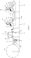
- a known paper press of the so-called Morgan type is built up from a series of units comprising an unwind unit 10, a web guide unit 12, an infeed unit 14, an infeed tower base unit 16, a basic tower base unit 18, a tower-plus-motor-drive base unit 20, a process unit 22, a folder/tension unit 24, and a rewind unit 26.
- a control console 27 is mounted on the units 24 and 26.
- Each of the tower base units 16, 18 and 20 carries an identical offset litho print tower 28, and more than one basic tower base unit 18 can be provided depending on the number of different colours to be printed in one pass.
- each print tower 28 includes an ink duct 30 from which ink is transferred through a series of cylinders indicated generally at 32 to a plate cylinder 34 which takes up the ink selectively over its surface and transfers it to a blanket cylinder 36 which transfers it in turn to the web 38 of paper as it passes between the blanket cylinder 36 and an impression cylinder 40.
- the plate cylinder 34 and the blanket cylinder 36 are mounted in knowm manner in a quick-change cartridge (not shown).
- the web 38 is drawn from a roll 42 through a festoon arrangement of cylinders indicated generally at 44 which includes dancing rolls 46 moveable vertically by changes in tension in the web. This movement pneumatically controls a brake (not shown) for the roll 42 so as to keep the unwinding tension constant.
- the web guide unit 12 includes an electronic eye (not shown) which senses one edge of the web 38 as it passes over a table 48 and in known manner controls the correction of any misalignment.
- the infeed unit 14 includes an infeed friction cylinder 50 around which the web 38 passes without slipping, thereby drawing the web from the roll 42, to which end said cylinder is sprayed with metal and then lightly ground so that its periphery remains rough although its diameter is extremely accurate.
- the friction cylinder 50 forms part of an improved infeed mechanism hereinafter described which constitutes the present invention.
- a web turnover mechanism 52 mounted in the infeed tower base unit 16 can turn the web 38 over in known manner if so desired after the first printing operation.
- the tower-plus-motor-drive base unit 20 houses drive means (not shown) for a sectional line-shaft 54 (see Figures 1 and 3), said means comprising an electric motor, pulleys and a toothed belt.
- the line-shaft 54 conventionally supplies synchronised drive to all of the units 16, 18, 20, 22 and 24.
- the friction cylinder 50 operates in accordance with known general principles whereby the ratio of its rotational speed relative to that of the line-shaft 54 is modulated to control lengthwise stretching of the web 38, and its angular position relative to that of the line-shaft 54 is adjusted to control the phase of the web 38 when it is re-inserted for a second or subsequent passes through the press in order to position the new print relative to the existing print.
- the line-shaft 54 supplies drive to the infeed unit 14 as will be hereinafter described.
- the process unit 22 includes a sprocket hole punching mechanism 56 and two perforating cylinders 58 and 59 running against respective anvil cylinders 60 and 61.
- the cylinder 61 acts as a metering cylinder for pulling the web 38 through the press in a controlled manner, to which end it runs against rubber nip rollers.
- the folder/tension unit 24 includes a web tension control cylinder 62 after which there is disposed an optional folding station (not shown).
- the rewind unit 26 comprises a roll 64 driven by an independent electric motor (not shown) which, if rolling rather than folding is required, draws the web 38 from the tension control cylinder 62 around a dancing roll 66 moveable vertically by changes in tension in the web. This movement regulates the speed of the motor which drives the roll 64.
- a brake (not shown) which is controlled manually by way of a potentiometer acts on a cylinder 68 so as to regulate the rewinding tension.
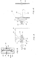
- an improved web infeed mechanism comprises, in addition to the friction cylinder 50, an extension 70 of the line-shaft 54 which drives the friction cylinder directly by way of a phase-shifting gearbox 72 which is close-coupled in series with a bevel gearbox 74.
- the output shaft 76 of the bevel gearbox 74 projects from both sides thereof, and the friction cylinder 50 is supported between one end of the shaft 76 and a bearing 78 mounted in one of the side frames 80 of the press.
- the phase-shifting gearbox 72 comprises epicyclic gearing consisting of a sun wheel 82 driven by the line-shaft extension 70, a plurality of planet pinions 84, say six as shown, which mesh with the sun wheel 82 and are rotateably mounted on a planet carrier 86 which drives the input shaft 88 of the bevel gearbox 74, and an internally-toothed annulus 90 which meshes with the planet pinions 84.
- a wormwheel 92 is formed on the periphery of the annulus 90, and a worm 94 which meshes with the wormwheel is formed on an additional or subsidiary drive shaft 96 of the phase-shifting gearbox 72.
- the epicyclic gearing of the gearbox 72 effects a reduction in speed of 3 to 1 to avoid over-speeding of the planet pinions 84, and the bevel gearbox effects an increase in speed of 1 to 3 to restore the status quo.
- a first position encoder 98 is driven directly by the line-shaft extension 70, and a second position encoder 100 is effectively driven directly by the friction cylinder 50 by way of the other end of the output shaft 76 of the bevel gearbox 74.
- the additional drive shaft 96 of the phase-shifting gearbox 72 is driven by an electric servo-motor 102 which is controlled by output signals from a combined phase-synchronising and ratio-modulating controller (not shown) which receives ratio-modulating input signals from the first and second encoders 98 and 100 whereby the speed of the rotation imparted to the friction cylinder 50 by the line-shaft extension 70 is continuously modified or trimmed.
- the combined phase-synchronising and ratio-modulating controller also receives phase-synchronising input signals sensed in known manner from equally-spaced marks printed on one margin of the web 38 and from a reference point on a gear (not shown) driven directly by the line-shaft 54, whereby the web is positioned to align new and existing printing. Said gear is crowded into mesh with a mating gear (not shown) on the line-shaft 54 to eliminate back-lash.
- the improved infeed mechanism is able to control ratio-modulating and phase-synchronising to within about 0.1 millimetres. This degree of accuracy is aided by the direct drives between the line-shaft 54 and the first encoder 98, and between the friction cylinder 50 and the second encoder 100, as well as between the line-shaft and the gear bearing the reference point, which eliminate transmission errors from the associated measurements.
- a press according to the invention has no print towers and base units therefor, but is simply designed for the dedicated processing of a continuous web of paper by, for example, repeatedly sprocket hole punching, perforating, and rolling, folding or cutting it. In a complementary modification, a press is simply designed to print without performing any such processing.
Landscapes
- Engineering & Computer Science (AREA)
- Mechanical Engineering (AREA)
- Controlling Rewinding, Feeding, Winding, Or Abnormalities Of Webs (AREA)
- Inking, Control Or Cleaning Of Printing Machines (AREA)
Description
Claims (11)
- An infeed mechanism for a paper press or the like, said infeed mechanism comprising a line-shaft (54) for driving various units of the press and an infeed friction cylinder (50) driven in timed relationship with the line-shaft, wherein the friction cylinder is arranged to be driven directly from the line-shaft by way of a phase-shifting gearbox (72) which is additionally driven by an electric servomotor (102) so controlled by out put signals from a controller which receives ratio-modulating input signals as to be capable of modifying the speed of the rotation imparted to the friction cylinder by the line-shaft to control the lengthwise stretching of the web, characterised in that the controller is a combined phase-synchronising and ratio-modulating controller which also receives phase-synchronising input signals so that the angular position of the infeed friction cylinder(50) relative to that of the line-shaft (54) can also be adjusted to control the position or phase of the web.
- An infeed mechanism according to claim 1, wherein the friction cylinder (50) is driven from the line-shaft (54) by way of a phase-shifting gearbox (72) in series with a bevel gearbox (74).
- An infeed mechanism according to claim 2, wherein the friction cylinder (50) is supported between the output shaft (76) of the bevel gearbox (74) and a bearing (78) mounted in the frame (80) of the press.
- An infeed mechanism according to claim 2 or claim 3, wherein the phase-shifting gearbox (72) comprises epicyclic gearing having an annulus (90) with a wormwheel (92) on its periphery and a worm (94) meshing with the wormwheel, the worm being on an additional drive shaft (96) of said gearbox.
- An infeed mechanism according to claim 4, wherein the epicyclic gearing effects a reduction in speed and the bevel gearbox (74) effects an increase in speed of the same order.
- An infeed mechanism according to any one of claims 2 to 5, wherein a first position encoder (98) is driven directl by the line-shaft (54) and a second position encoder (100) is drivendirectly by the friction cylinder (50).
- An infeed mechanism according to claim 6, wherein the second encoder (100) is driven from the friction cylinder (50) by way of the output shaft (76) of the bevel gearbox (74).
- An infeed mechanism according to claim 6 or claim 7, wherein the electric servo-motor (102) is controlled by the first and second encoders (98 and 100).
- An infeed mechanism according to claim 8, wherein the combined phase-synchronising and ratio-modulating controller receives ratio-modulating input signals from the first and second encoders (98 and 100).
- An infeed mechanism according to claim 9, wherein the combined phase-synchronising and ratio-modulating controller also receives phase-synchronising input signals sensed from marks printed on the web (38) and from a reference point on a gear driven directly by the line-shaft (54).
- A paper press of the so-called Morgan type provided with an infeed mechanism according to any one of the preceeding claims.
Applications Claiming Priority (2)
| Application Number | Priority Date | Filing Date | Title |
|---|---|---|---|
| GBGB9509138.5A GB9509138D0 (en) | 1995-05-01 | 1995-05-01 | Crabtree Morgan continuous forms paper press-infeed development |
| GB9509138 | 1995-05-01 |
Publications (3)
| Publication Number | Publication Date |
|---|---|
| EP0741014A2 EP0741014A2 (en) | 1996-11-06 |
| EP0741014A3 EP0741014A3 (en) | 1997-08-13 |
| EP0741014B1 true EP0741014B1 (en) | 2001-10-31 |
Family
ID=10774019
Family Applications (1)
| Application Number | Title | Priority Date | Filing Date |
|---|---|---|---|
| EP96303001A Expired - Lifetime EP0741014B1 (en) | 1995-05-01 | 1996-04-29 | An infeed mechanism for a paper press or the like |
Country Status (3)
| Country | Link |
|---|---|
| EP (1) | EP0741014B1 (en) |
| DE (1) | DE69616411T2 (en) |
| GB (1) | GB9509138D0 (en) |
Families Citing this family (1)
| Publication number | Priority date | Publication date | Assignee | Title |
|---|---|---|---|---|
| CN106042610A (en) * | 2016-06-29 | 2016-10-26 | 广东顺德德力印刷机械有限公司 | Intaglio press capable of realizing pre-registration |
Citations (1)
| Publication number | Priority date | Publication date | Assignee | Title |
|---|---|---|---|---|
| US4896808A (en) * | 1987-09-17 | 1990-01-30 | Koening & Bauer Aktiengesellschaft | Device for the controlled infeed of a web to a printing machine, method for regulating a corresponding control signal, and device for performing the method |
Family Cites Families (3)
| Publication number | Priority date | Publication date | Assignee | Title |
|---|---|---|---|---|
| FR1297289A (en) * | 1961-05-19 | 1962-06-29 | Etudes De Machines Speciales | Device for automatic presetting of different elements of a printing machine |
| US3677177A (en) * | 1970-07-28 | 1972-07-18 | Smith R P M Corp | Drive for controlling web length in rotary printing presses |
| GB2150121B (en) * | 1983-11-21 | 1987-06-24 | Taiyo Tekko Kk | Producing continuous business form stationery |
-
1995
- 1995-05-01 GB GBGB9509138.5A patent/GB9509138D0/en active Pending
-
1996
- 1996-04-29 EP EP96303001A patent/EP0741014B1/en not_active Expired - Lifetime
- 1996-04-29 DE DE1996616411 patent/DE69616411T2/en not_active Expired - Fee Related
Patent Citations (1)
| Publication number | Priority date | Publication date | Assignee | Title |
|---|---|---|---|---|
| US4896808A (en) * | 1987-09-17 | 1990-01-30 | Koening & Bauer Aktiengesellschaft | Device for the controlled infeed of a web to a printing machine, method for regulating a corresponding control signal, and device for performing the method |
Also Published As
| Publication number | Publication date |
|---|---|
| DE69616411T2 (en) | 2002-07-11 |
| GB9509138D0 (en) | 1995-06-28 |
| EP0741014A3 (en) | 1997-08-13 |
| DE69616411D1 (en) | 2001-12-06 |
| EP0741014A2 (en) | 1996-11-06 |
Similar Documents
| Publication | Publication Date | Title |
|---|---|---|
| JP3180291B2 (en) | Paper tension control device in form printing machine | |
| US3841216A (en) | Method of and apparatus for correcting deviations in length and registration in a continuous strip of material | |
| DE69113613T2 (en) | SYSTEM FOR AUTONOMOUS TREATMENT OF A MATERIAL RAIL. | |
| US4732082A (en) | Apparatus and method for mounting embossing rollers in a press line | |
| GB1567243A (en) | Printing and die-cutting apparatus | |
| US6062751A (en) | Belt-driven printer-cutter machine for corrugated paperboard of varying thickness | |
| US4473009A (en) | Apparatus for varying the position of a printing operation performed on a web | |
| JP4235960B2 (en) | Printing device for long printed matter | |
| EP0267007B1 (en) | An apparatus for controlling paper transfer speed of printing section of a form printing machine | |
| US5383393A (en) | Multicolor lithographic rotary press | |
| US2334074A (en) | Variable speed control apparatus | |
| EP0857105A1 (en) | Box blank printer/slotter apparatus | |
| JP2561886B2 (en) | How to change the online theta and cut length of a printing device | |
| JPH0286445A (en) | Flexographic press | |
| JPS6315749A (en) | Method and device for controlling synchronization of belt-type printer | |
| US20100028066A1 (en) | Printing apparatus | |
| CN101301797A (en) | Print groover with die-cutting portion equipped with rubber cushion roller speed-chasing mechanism | |
| US3335928A (en) | Control of web elongation | |
| EP0741014A2 (en) | An infeed mechanism for a paper press or the like | |
| GB2145663A (en) | Method and apparatus for regulating printing in printing machines | |
| US6295925B1 (en) | Web tension control system and method for flexographic tag and label presses | |
| GB2300413A (en) | Infeed mechanism for a paper press | |
| EP1026111A2 (en) | Injector for rotary web processing device with fixed diameter base | |
| JPH0272951A (en) | Multi-color offset press | |
| US3630426A (en) | Train of feed rolls for paper, plastics or textile webs |
Legal Events
| Date | Code | Title | Description |
|---|---|---|---|
| PUAI | Public reference made under article 153(3) epc to a published international application that has entered the european phase |
Free format text: ORIGINAL CODE: 0009012 |
|
| AK | Designated contracting states |
Kind code of ref document: A2 Designated state(s): DE ES FR GB IE IT NL |
|
| PUAL | Search report despatched |
Free format text: ORIGINAL CODE: 0009013 |
|
| AK | Designated contracting states |
Kind code of ref document: A3 Designated state(s): DE ES FR GB IE IT NL |
|
| 17P | Request for examination filed |
Effective date: 19980213 |
|
| 17Q | First examination report despatched |
Effective date: 19990217 |
|
| GRAG | Despatch of communication of intention to grant |
Free format text: ORIGINAL CODE: EPIDOS AGRA |
|
| GRAG | Despatch of communication of intention to grant |
Free format text: ORIGINAL CODE: EPIDOS AGRA |
|
| GRAH | Despatch of communication of intention to grant a patent |
Free format text: ORIGINAL CODE: EPIDOS IGRA |
|
| GRAH | Despatch of communication of intention to grant a patent |
Free format text: ORIGINAL CODE: EPIDOS IGRA |
|
| GRAA | (expected) grant |
Free format text: ORIGINAL CODE: 0009210 |
|
| AK | Designated contracting states |
Kind code of ref document: B1 Designated state(s): DE ES FR GB IE IT NL |
|
| PG25 | Lapsed in a contracting state [announced via postgrant information from national office to epo] |
Ref country code: IT Free format text: LAPSE BECAUSE OF FAILURE TO SUBMIT A TRANSLATION OF THE DESCRIPTION OR TO PAY THE FEE WITHIN THE PRESCRIBED TIME-LIMIT;WARNING: LAPSES OF ITALIAN PATENTS WITH EFFECTIVE DATE BEFORE 2007 MAY HAVE OCCURRED AT ANY TIME BEFORE 2007. THE CORRECT EFFECTIVE DATE MAY BE DIFFERENT FROM THE ONE RECORDED. Effective date: 20011031 |
|
| REF | Corresponds to: |
Ref document number: 69616411 Country of ref document: DE Date of ref document: 20011206 |
|
| REG | Reference to a national code |
Ref country code: IE Ref legal event code: FG4D |
|
| REG | Reference to a national code |
Ref country code: GB Ref legal event code: IF02 |
|
| PG25 | Lapsed in a contracting state [announced via postgrant information from national office to epo] |
Ref country code: IE Free format text: LAPSE BECAUSE OF NON-PAYMENT OF DUE FEES Effective date: 20020429 |
|
| PG25 | Lapsed in a contracting state [announced via postgrant information from national office to epo] |
Ref country code: ES Free format text: LAPSE BECAUSE OF FAILURE TO SUBMIT A TRANSLATION OF THE DESCRIPTION OR TO PAY THE FEE WITHIN THE PRESCRIBED TIME-LIMIT Effective date: 20020430 |
|
| PLBE | No opposition filed within time limit |
Free format text: ORIGINAL CODE: 0009261 |
|
| STAA | Information on the status of an ep patent application or granted ep patent |
Free format text: STATUS: NO OPPOSITION FILED WITHIN TIME LIMIT |
|
| 26N | No opposition filed | ||
| REG | Reference to a national code |
Ref country code: IE Ref legal event code: MM4A |
|
| PGFP | Annual fee paid to national office [announced via postgrant information from national office to epo] |
Ref country code: FR Payment date: 20030429 Year of fee payment: 8 |
|
| PGFP | Annual fee paid to national office [announced via postgrant information from national office to epo] |
Ref country code: NL Payment date: 20030430 Year of fee payment: 8 Ref country code: GB Payment date: 20030430 Year of fee payment: 8 |
|
| PGFP | Annual fee paid to national office [announced via postgrant information from national office to epo] |
Ref country code: DE Payment date: 20030528 Year of fee payment: 8 |
|
| PG25 | Lapsed in a contracting state [announced via postgrant information from national office to epo] |
Ref country code: GB Free format text: LAPSE BECAUSE OF NON-PAYMENT OF DUE FEES Effective date: 20040429 |
|
| PG25 | Lapsed in a contracting state [announced via postgrant information from national office to epo] |
Ref country code: NL Free format text: LAPSE BECAUSE OF NON-PAYMENT OF DUE FEES Effective date: 20041101 |
|
| PG25 | Lapsed in a contracting state [announced via postgrant information from national office to epo] |
Ref country code: DE Free format text: LAPSE BECAUSE OF NON-PAYMENT OF DUE FEES Effective date: 20041103 |
|
| GBPC | Gb: european patent ceased through non-payment of renewal fee |
Effective date: 20040429 |
|
| PG25 | Lapsed in a contracting state [announced via postgrant information from national office to epo] |
Ref country code: FR Free format text: LAPSE BECAUSE OF NON-PAYMENT OF DUE FEES Effective date: 20041231 |
|
| NLV4 | Nl: lapsed or anulled due to non-payment of the annual fee |
Effective date: 20041101 |
|
| REG | Reference to a national code |
Ref country code: FR Ref legal event code: ST |