EP0267007B1 - An apparatus for controlling paper transfer speed of printing section of a form printing machine - Google Patents
An apparatus for controlling paper transfer speed of printing section of a form printing machine Download PDFInfo
- Publication number
- EP0267007B1 EP0267007B1 EP87309727A EP87309727A EP0267007B1 EP 0267007 B1 EP0267007 B1 EP 0267007B1 EP 87309727 A EP87309727 A EP 87309727A EP 87309727 A EP87309727 A EP 87309727A EP 0267007 B1 EP0267007 B1 EP 0267007B1
- Authority
- EP
- European Patent Office
- Prior art keywords
- printing
- cylinder
- speed
- paper
- drive
- Prior art date
- Legal status (The legal status is an assumption and is not a legal conclusion. Google has not performed a legal analysis and makes no representation as to the accuracy of the status listed.)
- Expired - Lifetime
Links
Images


Classifications
-
- B—PERFORMING OPERATIONS; TRANSPORTING
- B41—PRINTING; LINING MACHINES; TYPEWRITERS; STAMPS
- B41F—PRINTING MACHINES OR PRESSES
- B41F13/00—Common details of rotary presses or machines
- B41F13/02—Conveying or guiding webs through presses or machines
-
- B—PERFORMING OPERATIONS; TRANSPORTING
- B41—PRINTING; LINING MACHINES; TYPEWRITERS; STAMPS
- B41F—PRINTING MACHINES OR PRESSES
- B41F13/00—Common details of rotary presses or machines
- B41F13/0008—Driving devices
-
- B—PERFORMING OPERATIONS; TRANSPORTING
- B41—PRINTING; LINING MACHINES; TYPEWRITERS; STAMPS
- B41P—INDEXING SCHEME RELATING TO PRINTING, LINING MACHINES, TYPEWRITERS, AND TO STAMPS
- B41P2213/00—Arrangements for actuating or driving printing presses; Auxiliary devices or processes
- B41P2213/10—Constitutive elements of driving devices
- B41P2213/20—Gearings
- B41P2213/208—Harmonic drive
Definitions
- the present invention relates to a form printing machine and is particularly concerned with cotrolling paper transfer speed of a printing section of a form printing machine which carries out successive steps from multicolor printing on a paper web to processing, such as punching and perforating.
- a paper feeding section 1 for transferring a paper web P from a roll
- a printing section 2 for achieving multicolor offset printing on the fed paper web P
- a processing section 3 for processing, for example, punching, perforating and the like the printed paper web P which is transferred from the printing section 2
- a paper discharge section for discharging the printed and processed paper web into a zigzag folded stack.
- printing units 5 are arranged on a printing line.
- the number of the printing units 5 coincides with the number of colors used in the multicolor printing, and in Fig.9, four printing units which coincide with the four color printing are arranged.
- the paper web P is successively passed through each of the printing units 5... and printed in multicolor.
- Each printing unit 5 comprises a plate cylinder 6, a blanket cylinder 7 formed of an elastic material such as rubber onto which images on the plate cylinder are transferred and a metal impression cylinder 8, these three cylinders being rotatably supported by a printing cylinder support in such a manner that their circumferential surfaces are substantially in contact with one another.
- the paper web P is passed between the blanket cylinder 7 and the impression cylinder 8, where the image transferred from the plate cylinder 6 onto the blanket cylinder 7 is printed on the paper web P.
- a drive motor (not shown) is transmitted through a drive shaft 11 to each of the printing units 5.
- the drive shaft 11 extends along the paper feed section 1 and all of the printing units 5...of the printing section 2.
- the rotation of the drive shaft 11 is transmitted through a transmission device 12 such as a worm gear mechanism to an infeed roll 10 and through a transmission gear 13 to the plate cylinders 6 of the printing units 5.
- spur gears 14, 15, 16 are mounted respectively on the rotatory shafts 6a, 7a, 8a respectively of the plate cylinder 6, the blanket cylinder 7 and the impression cylinder 8 of each printing unit 5.
- the rotation of the spur gears 14, 15, 16 in engagement with one another, the rotation of the drive shaft 11 is transmitted to the plate cylinder 6, the blanket cylinder 7 and the impression cylinder 8.
- these cylinders 6, 7, 8 are rotated.
- the speed of transfer of the paper web P (hereinafter referred to as the paper transfer speed) of the printing unit 5 is controlled by the rotation speed of the blanket cylinder 7 and the impression cylinder 8, but it is also changed in accordance with the change of the thickness of the paper web P.
- d is the diameter of the impression cylinder 8
- N is the rotation frequency of the impression cylinder 8
- t is the thickness of the paper web P
- V is the paper transfer speed
- the paper transfer speed is changed by the relation of the nonelastic impression cylinder 8 and the paper thickness.
- the paper transfer speed is determined by the rotation speed of the impression cylinder 8 and the paper thickness.
- the paper thickness changes within the range from 0.05mm to 0.2mm. Therefore, for the paper transfer speed V, the following formulas are obtained.
- Japanese Patent Application 60-94353 discloses a printing section having common speed changing means 13 operative to adjust the speed of all the impression cylinders together, to compensate for change of their diameter. No compensation for paper thickness is mentioned.
- An object of the present invention is to overcome the above-mentioned problems.
- the rotation speed of the impression cylinder of each printing unit namely the paper transfer speed
- the rotation speed of the impression cylinder of each printing unit can be controlled in correspondence with the change of the paper thickness.
- the rotation speed of the impression cylinder of each printing unit can be controlled in accordance with the variation of the diameter of the impression cylinder between the printing units and the like, whereby the printing pitch can be suitably maintained.
- FIG. 4 An embodiment of the present invention is shown in Figs. 4 and 5.
- the same parts as the part shown in Figs. 6 to 9 are indicated with the same numerals and duplication of description will be avoided.
- the rotary power of a drive shaft 11 is transmitted through a transmission device 12 to an infeed roll 10 and at the same time transmitted through a transmission device 13 to the plate cylinder 6 of each printing unit 5.
- the rotary power of the plate cylinder 6 is transmitted directly to the blanket cylinder 7, and the rotary power of the blanket cylinder 7 is transmitted through a differential device 23 functioning as a speed change means to the impression cylinder 8.
- the differential device 23 the rotation speed of the impression cylinder 8 can be controlled independently of the plate cylinder 6 and the blanket cylinder 7, whereby the paper transfer speed can be controlled.
- Spur gears 14, 15 are mounted respectively on the rotary shafts 6a, 7a of the plate cylinder 6 and the blanket cylinder 7 in such a manner that the spur gears 14, 15 are in engagement with each other.
- two spur gears 51, 52 are mounted on the rotary shaft 8a of the impression cylinder 8 and the spur gear 51 is in engagement with the spur gear 15 of the blanket cylinder 7.
- the spur gear 51 (hereinafter referred to as the transmission gear 51) is mounted through bearing 53 on the shaft 8a while the spur gear 52 (hereinafter referred to as the output gear 52) is mounted directly on the shaft 8a, and the differential device 23 is provided between the two gears 51, 52.
- the differential device 23 is illustrated in Fig. 2 and is referred as to a harmonic drive. It comprises an ellipsoidal wave generator 32, a flex spline 30 deformable into an ellipsoidal form by the rotation of a wave generator 32, and a pair of circular spines 34, 35, each provided with internal teeth which are engageable with the longitudinal portion, of the flex spline 30.
- One circular spine 34 is engaged through a spur gear 36 with the transmission gear 51, while the other circular spline 35 is engaged through the spur gear 37 with the output gear 52.
- the wave generator 32 is mounted on the regulating spindle 38 so as to be integratedly rotatable with the regulating spindle 38.
- the regulating spindle 38 is rotatively driven through a belt transmission mechanism 39 by a regulating motor 40.
- the rotary power of the transmission gear 51 is transmitted to the output gear 52 via the spur gear 36 ⁇ the circular spine 34 ⁇ the flex spline 33 the circular spline 35 ⁇ the spur gear 37.
- the rotatory power of the regulating motor 40 is transmitted via the belt transmission mechanism 39 ⁇ the regulating spindle 38 ⁇ the wave generator 32, and by the rotation of the wave generation 32, the flex spline 33 is deformed into an ellipsoidal form and at the same time the longitudinal portion of the flex spline 33 comes into engagement successively with the internal teeth of the circular splines 34, 35.
- the flex spine 33 since the number of the teeth of the flex spine 33 is smaller by a few (e.g. by two) than that of the circular spines 34, 35, the flex spine 33 is moved in the corresponding distance in the direction opposite to the direction of the rotation of the wave generator 32. This movement is taken out as a differential output by the output gear 52, and thereby the impression cylinder 8 is rotated at the speed determined by the differential device 23.
- the output rotation speed of the differential device 23 can be freely changed by controlling the rotation speed of the regulating motor 40, and thereby the speed ratio of the impression cylinder 8 to the blanket cylinder 7 of each printing section 5 can be controlled.
- the ratio of the input speed to the output speed of the differential device 23 is R:(R+1).
- R is the reduction gear ratio of the differential device 23.
- the rotation speed of the impression cylinder 8 of each printing unit 5, namely, the paper transfer speed of the printing section 2 can be freely controlled as abovementioned. Therefore, the printing pitch can be maintained uniform by reducing the rotation of the impression cylinder 8 thus to lower the paper transfer speed when the paper thickness is larger than the standard value, and by controlling reversely when the paper thickness is smaller. Consequently, it can be assuredly prevented that the obtained print is blurred due to the disharmony of the rotation speed of the blanket cylinder 7 with the paper transfer speed and that a high tension is applied on the paper web P and the paper transfer mechanism between the printing section 2 and the paper feed section 1 or the processing section 3 due to the change of the printing pitch. Further, when the difference of the paper transfer speed between the printing units 5...
- Fig. 5 Another example of the differential device 23 is shown in Fig. 5.
- the regulating spindle 38 is rotatively driven by another drive source i.e. the variable-speed regulating motor 40, but in the example shown in Fig. 5, the rotary power of the blanket cylinder 7 is introduced into a gear type or other speed change device 53 the reduction gear ratio of which can be controlled by manual operation, and the output thereof is transmitted through the belt transmission mechanism 54 to the regulating spindle 38 so as to function as a drive force.
- another drive source i.e. the variable-speed regulating motor 40
- the rotary power of the blanket cylinder 7 is introduced into a gear type or other speed change device 53 the reduction gear ratio of which can be controlled by manual operation, and the output thereof is transmitted through the belt transmission mechanism 54 to the regulating spindle 38 so as to function as a drive force.
- the speed change means for controlling the speeds of the impression cylinders 8... of the printing units 5... is not limited to the abovementioned differential device 23 but may comprise a gear type, belt type or other general speed change device.
- the use of the differential device 23 shown in the above embodiments is advantageous in that fine speed change control can be thereby achived with a high accuracy.
- the rotation of the blanket cylinder of each printing unit of the printing section is transmitted through the speed change means such as the differential device to the impression cylinder, and the rotation speed of the impression cylinder, namely, the paper transfer speed can be control led by the speed change means. Consequently by controlling the paper transfer speed in correspondence with the paper thickness, the difference of the diameter of the impression cylinder between the printing units and the like, the printing pitch can be always suitably maintained thus to improve the printing precision and at the same time application of high tension to the paper web and the paper transfer mechanism between the printing section and the paper feed section or the processing section of a multicolor printing machine is prevented, whereby the life span of the paper transfer mechanism of each section can be increased.
Description
- The present invention relates to a form printing machine and is particularly concerned with cotrolling paper transfer speed of a printing section of a form printing machine which carries out successive steps from multicolor printing on a paper web to processing, such as punching and perforating.
- The whole structure of a typical multicolor form printing machine is shown in Fig.9 of the appended drawings. In this Figure, there is illustrated a paper feeding section 1 for transferring a paper web P from a roll, a
printing section 2 for achieving multicolor offset printing on the fed paper web P, aprocessing section 3 for processing, for example, punching, perforating and the like the printed paper web P which is transferred from theprinting section 2, and a paper discharge section for discharging the printed and processed paper web into a zigzag folded stack. - In the
printing section 2,printing units 5 are arranged on a printing line. The number of theprinting units 5 coincides with the number of colors used in the multicolor printing, and in Fig.9, four printing units which coincide with the four color printing are arranged. The paper web P is successively passed through each of theprinting units 5... and printed in multicolor. Eachprinting unit 5 comprises aplate cylinder 6, ablanket cylinder 7 formed of an elastic material such as rubber onto which images on the plate cylinder are transferred and ametal impression cylinder 8, these three cylinders being rotatably supported by a printing cylinder support in such a manner that their circumferential surfaces are substantially in contact with one another. The paper web P is passed between theblanket cylinder 7 and theimpression cylinder 8, where the image transferred from theplate cylinder 6 onto theblanket cylinder 7 is printed on the paper web P. - As shown in Fig. 6, the rotation of a drive motor(not shown) is transmitted through a
drive shaft 11 to each of theprinting units 5. Thedrive shaft 11 extends along the paper feed section 1 and all of theprinting units 5...of theprinting section 2. The rotation of thedrive shaft 11 is transmitted through atransmission device 12 such as a worm gear mechanism to an infeedroll 10 and through atransmission gear 13 to theplate cylinders 6 of theprinting units 5.... - As shown in Fig. 7,
spur gears rotatory shafts plate cylinder 6, theblanket cylinder 7 and theimpression cylinder 8 of eachprinting unit 5. By the rotation of thespur gears drive shaft 11 is transmitted to theplate cylinder 6, theblanket cylinder 7 and theimpression cylinder 8. Thus, thesecylinders - In this case, the speed of transfer of the paper web P (hereinafter referred to as the paper transfer speed) of the
printing unit 5 is controlled by the rotation speed of theblanket cylinder 7 and theimpression cylinder 8, but it is also changed in accordance with the change of the thickness of the paper web P. Namely, in Fig. 12, if d is the diameter of theimpression cylinder 8; N is the rotation frequency of theimpression cylinder 8; t is the thickness of the paper web P; and V is the paper transfer speed, a formula

is obtained. And therefore, as the thickness t of the paper web P (hereinafter referred to as the paper thickness t) increases, the paper transfer speed V rises and the paper transfer amount per unit time increases. - In the case of the
blanket cylinder 7, the change of the paper thickness is compensated by diameter change due to the elasticity of theblanket cylinder 7, and therefore, the paper transfer speed is changed by the relation of thenonelastic impression cylinder 8 and the paper thickness. In other words, the paper transfer speed is determined by the rotation speed of theimpression cylinder 8 and the paper thickness. Further, generally in a business form printing machine, the paper thickness changes within the range from 0.05mm to 0.2mm. Therefore, for the paper transfer speed V, the following formulas are obtained.
Minimum value
Minimum value
In a conventional printing machine, however, since theimpression cylinder 8 is always rotated together with theblanket cylinder 7 at a predetermined speed, independently of the paper thickness, the paper transfer speed changes with the change of the paper thickness. As a result, the following problems have been caused. - 1. In the
printing unit 5, monocolor or multicolor, the change of the paper transfer speed with respect to theblanket cylinder 7 rotating at a constant speed (i.e. the change of the printing pitch) causes the unevenness of printing precision. - 2. Due to the change of the printing pitch, the tension of the paper web P of the
printing section 2 become different from that of the preceding paper feed section 1 or of the followingprocessing section 3. Consequently, a high tension is applied to the paper web P and a paper transfer mechanism, which causes the paper web P to be broken and the life span of the paper transfer mechanism to be shortened. - 3. In multicolor printing, the difference of the diameters of the impression cylinders of the
printing units 5 causes variation of the paper transfer speed between the printing units i.e. variation of the printing pitch therebetween, whereby the similar problems have arisen. - Japanese Patent Application 60-94353 discloses a printing section having common
speed changing means 13 operative to adjust the speed of all the impression cylinders together, to compensate for change of their diameter. No compensation for paper thickness is mentioned. - An object of the present invention is to overcome the above-mentioned problems.
- The form printing machine of the present invention is set out in claim 1.
- With this arrangement of the invention, firstly the rotation speed of the impression cylinder of each printing unit, namely the paper transfer speed, can be controlled in correspondence with the change of the paper thickness. Secondly, the rotation speed of the impression cylinder of each printing unit can be controlled in accordance with the variation of the diameter of the impression cylinder between the printing units and the like, whereby the printing pitch can be suitably maintained.
- Fig. 1 is a schematic view illustrating an embodiment of the apparatus according to the present invention;
- Fig. 2 is a sectional view of a differential device suitable for use as a speed changing means in the present invention;
- Fig. 3 is a detailed side view of the apparatus of Fig. 1;
- Fig. 4 is a view illustrating the principle of the operation of a differential device used as a speed change means in the embodiment of Figs. 1 to 3;
- Fig. 5 is a view similar to Fig. 3 illustrating another example of the differential device;
- Fig. 6 is a view similar to Fig. 1 illustrating the prior art;
- Fig. 7 is a view similar to Fig. 3 illustrating the drive system of the printing unit in the prior art;
- Fig. 8 is a partly extended front view of the drive system; and
- Fig. 9 is a view illustrating the general structure of the form printing machine.
- An embodiment of the present invention is shown in Figs. 4 and 5. Here in the explanation of the embodiment, the same parts as the part shown in Figs. 6 to 9 are indicated with the same numerals and duplication of description will be avoided.
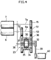
- Referring to Fig. 4; the rotary power of a
drive shaft 11 is transmitted through atransmission device 12 to an infeedroll 10 and at the same time transmitted through atransmission device 13 to theplate cylinder 6 of eachprinting unit 5. Then in eachprinting unit 5 the rotary power of theplate cylinder 6 is transmitted directly to theblanket cylinder 7, and the rotary power of theblanket cylinder 7 is transmitted through adifferential device 23 functioning as a speed change means to theimpression cylinder 8. By thedifferential device 23, the rotation speed of theimpression cylinder 8 can be controlled independently of theplate cylinder 6 and theblanket cylinder 7, whereby the paper transfer speed can be controlled. - The particular structure of the power transmission system, including the
differential device 23, of eachprinting unit 5 will be described with reference to Fig. 3.Spur gears rotary shafts plate cylinder 6 and theblanket cylinder 7 in such a manner that thespur gears spur gears rotary shaft 8a of theimpression cylinder 8 and thespur gear 51 is in engagement with thespur gear 15 of theblanket cylinder 7. The spur gear 51 (hereinafter referred to as the transmission gear 51) is mounted throughbearing 53 on theshaft 8a while the spur gear 52 (hereinafter referred to as the output gear 52) is mounted directly on theshaft 8a, and thedifferential device 23 is provided between the twogears - The
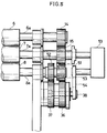
differential device 23 is illustrated in Fig. 2 and is referred as to a harmonic drive. It comprises anellipsoidal wave generator 32, aflex spline 30 deformable into an ellipsoidal form by the rotation of awave generator 32, and a pair ofcircular spines flex spline 30. - The principle of the operation of the
differential device 23 will be described with reference to Figs. 3 to 5 Onecircular spine 34 is engaged through aspur gear 36 with thetransmission gear 51, while the othercircular spline 35 is engaged through thespur gear 37 with theoutput gear 52. Thewave generator 32 is mounted on the regulatingspindle 38 so as to be integratedly rotatable with the regulatingspindle 38. The regulatingspindle 38 is rotatively driven through abelt transmission mechanism 39 by a regulatingmotor 40. The rotary power of thetransmission gear 51 is transmitted to theoutput gear 52 via thespur gear 36 → thecircular spine 34 → the flex spline 33 thecircular spline 35 → thespur gear 37. On the other hand, the rotatory power of the regulatingmotor 40 is transmitted via thebelt transmission mechanism 39 → the regulatingspindle 38 → thewave generator 32, and by the rotation of thewave generation 32, the flex spline 33 is deformed into an ellipsoidal form and at the same time the longitudinal portion of the flex spline 33 comes into engagement successively with the internal teeth of thecircular splines circular spines wave generator 32. This movement is taken out as a differential output by theoutput gear 52, and thereby theimpression cylinder 8 is rotated at the speed determined by thedifferential device 23. - The output rotation speed of the
differential device 23 can be freely changed by controlling the rotation speed of the regulatingmotor 40, and thereby the speed ratio of theimpression cylinder 8 to theblanket cylinder 7 of eachprinting section 5 can be controlled. When the rotation of the regulatingmotor 40 is stopped, the ratio of the input speed to the output speed of thedifferential device 23 is R:(R+1). Here, R is the reduction gear ratio of thedifferential device 23. - The rotation speed of the
impression cylinder 8 of eachprinting unit 5, namely, the paper transfer speed of theprinting section 2 can be freely controlled as abovementioned. Therefore, the printing pitch can be maintained uniform by reducing the rotation of theimpression cylinder 8 thus to lower the paper transfer speed when the paper thickness is larger than the standard value, and by controlling reversely when the paper thickness is smaller. Consequently, it can be assuredly prevented that the obtained print is blurred due to the disharmony of the rotation speed of theblanket cylinder 7 with the paper transfer speed and that a high tension is applied on the paper web P and the paper transfer mechanism between theprinting section 2 and the paper feed section 1 or theprocessing section 3 due to the change of the printing pitch. Further, when the difference of the paper transfer speed between theprinting units 5... is caused by the difference of the diameter of the impression cylinders, by controlling the paper transfer speed of one or both of theunits 5 as abovementioned a high tension can be prevented from being applied on the paper web P and the paper transfer mechanism between theprinting unit 2 and the paper feed section 1 or theprocessing unit 3. - Another example of the
differential device 23 is shown in Fig. 5. In the embodiment of Figs. 2 and 3, the regulatingspindle 38 is rotatively driven by another drive source i.e. the variable-speed regulating motor 40, but in the example shown in Fig. 5, the rotary power of theblanket cylinder 7 is introduced into a gear type or otherspeed change device 53 the reduction gear ratio of which can be controlled by manual operation, and the output thereof is transmitted through thebelt transmission mechanism 54 to the regulatingspindle 38 so as to function as a drive force. - The speed change means for controlling the speeds of the
impression cylinders 8... of theprinting units 5... is not limited to the abovementioneddifferential device 23 but may comprise a gear type, belt type or other general speed change device. However, the use of thedifferential device 23 shown in the above embodiments is advantageous in that fine speed change control can be thereby achived with a high accuracy. - With the use of the illustrated apparatus, as abovementioned, the rotation of the blanket cylinder of each printing unit of the printing section is transmitted through the speed change means such as the differential device to the impression cylinder, and the rotation speed of the impression cylinder, namely, the paper transfer speed can be control led by the speed change means. Consequently by controlling the paper transfer speed in correspondence with the paper thickness, the difference of the diameter of the impression cylinder between the printing units and the like, the printing pitch can be always suitably maintained thus to improve the printing precision and at the same time application of high tension to the paper web and the paper transfer mechanism between the printing section and the paper feed section or the processing section of a multicolor printing machine is prevented, whereby the life span of the paper transfer mechanism of each section can be increased.
Claims (4)
- A form printing machine having a plurality of printing units (5) each comprising a plate cylinder (6), a blanket cylinder (7) and an impression cylinder (8) and drive means (11,12,13,23) to drive said cylinders (6,7,8) including speed differential means (23) for causing said impression cylinders (8) to rotate at a predetermined speed difference relative to said plate cylinders (6) and blanket cylinders (7), characterised in that
in each said printing unit, said drive means has speed differential means (23) for the impression cylinder (8) thereof to rotate at a said speed difference relative to the plate cylinder (6) and blanket cylinder (7) thereof, the speed differential means (23) of the respective printing units being independently adjustable. - A form printing machine according to claim 1 wherein said speed differential means (23) of each printing unit is a harmonic drive.
- A form printing machine according to claim 1 wherein said drive means has a drive shaft (11) driving each said printing unit (5) and at each printing unit (5) a branch shaft driving said plate cylinder (6), said impression cylinder (8) in each unit (5) being driven from said branch shaft via said plate cylinder (6), and said speed differential means (23) for the impression cylinder in each printing unit (5) being interposed in the drive between said plate cylinder (6) and said impression cylinder (8).
- A form printing machine according to claim 3 wherein in each printing unit (5) said impression cylinder (8) is driven from said plate cylinder (6) via said blanket cylinder (7), and said speed differential means (23) is interposed in the drive between said blanket cylinder (7) and said impression cylinder (8).
Applications Claiming Priority (4)
| Application Number | Priority Date | Filing Date | Title |
|---|---|---|---|
| JP263523/86 | 1986-11-04 | ||
| JP61263522A JPS63115750A (en) | 1986-11-04 | 1986-11-04 | Paper feed adjusting device at printing section in form printer |
| JP61263523A JPS63117864A (en) | 1986-11-04 | 1986-11-04 | Paper feed regulating device for printing part of form printer |
| JP263522/86 | 1986-11-04 |
Publications (3)
| Publication Number | Publication Date |
|---|---|
| EP0267007A2 EP0267007A2 (en) | 1988-05-11 |
| EP0267007A3 EP0267007A3 (en) | 1989-08-30 |
| EP0267007B1 true EP0267007B1 (en) | 1994-03-16 |
Family
ID=26546049
Family Applications (1)
| Application Number | Title | Priority Date | Filing Date |
|---|---|---|---|
| EP87309727A Expired - Lifetime EP0267007B1 (en) | 1986-11-04 | 1987-11-03 | An apparatus for controlling paper transfer speed of printing section of a form printing machine |
Country Status (4)
| Country | Link |
|---|---|
| US (1) | US4785734A (en) |
| EP (1) | EP0267007B1 (en) |
| CA (1) | CA1278219C (en) |
| DE (1) | DE3789351T2 (en) |
Families Citing this family (18)
| Publication number | Priority date | Publication date | Assignee | Title |
|---|---|---|---|---|
| JPS6455025U (en) * | 1987-09-30 | 1989-04-05 | ||
| US4953461A (en) * | 1988-05-20 | 1990-09-04 | Harris Graphics Corporation | System for continuously rotating plate a blanket cylinders at relatively different surface speeds |
| DE4012396A1 (en) * | 1990-04-19 | 1991-10-31 | Roland Man Druckmasch | PRINTING MACHINE |
| US5127324A (en) * | 1990-11-06 | 1992-07-07 | Heidelberg Harris Gmbh | Adjustment apparatus with DC drive system for use in a printing press |
| DE4210777C2 (en) * | 1992-04-01 | 1995-07-06 | Roland Man Druckmasch | Pull roller pair, especially on printing machines |
| DE4241807A1 (en) * | 1992-12-11 | 1994-06-16 | Heidelberger Druckmasch Ag | Drive for a printing press |
| GB2283939A (en) * | 1993-11-16 | 1995-05-24 | Cobden Chadwick | Printing machine motor drives |
| CA2166341A1 (en) * | 1994-12-30 | 1996-07-01 | Thomas J. Kacmarcik | Method and apparatus for printing bingo books |
| US5765482A (en) * | 1996-10-02 | 1998-06-16 | Integrated Design Corporation | Web printing apparatus |
| JP3180291B2 (en) * | 1997-11-10 | 2001-06-25 | 株式会社ミヤコシ | Paper tension control device in form printing machine |
| US6003988A (en) * | 1997-12-23 | 1999-12-21 | Scitex Digital Printing, Inc. | Printer architecture |
| JP4318109B2 (en) * | 1999-04-28 | 2009-08-19 | 株式会社ミヤコシ | Paper feed speed adjusting device for printing section in form printing machine |
| US7771010B2 (en) * | 2006-02-03 | 2010-08-10 | Rr Donnelley | Apparatus for printing using a plurality of printing cartridges |
| US7708861B2 (en) | 2006-02-03 | 2010-05-04 | Rr Donnelley | Formulations for high speed print processing |
| WO2013025533A1 (en) | 2011-08-12 | 2013-02-21 | Moore Wallace North America, Inc. | Apparatus and method for disposing inkjet cartridges in a carrier |
| JP7083811B2 (en) * | 2017-03-24 | 2022-06-13 | 住友重機械工業株式会社 | Control device |
| DE102021118033A1 (en) * | 2021-07-13 | 2023-01-19 | Koenig & Bauer Ag | Processing machine and method for setting a print length and/or processing length |
| DE102021118031A1 (en) * | 2021-07-13 | 2023-01-19 | Koenig & Bauer Ag | Processing machine and method for setting a processing length of a shaping unit of a processing machine |
Family Cites Families (13)
| Publication number | Priority date | Publication date | Assignee | Title |
|---|---|---|---|---|
| US2690120A (en) * | 1948-12-21 | 1954-09-28 | St Regis Paper Co | Ink control means for rotary multicolor printing presses |
| US2758541A (en) * | 1951-04-12 | 1956-08-14 | Tison Rene Augustin | Rotary printing apparatus |
| US2729982A (en) * | 1954-04-16 | 1956-01-10 | Hamilton Tool Co | Governor-drum drive for printing presses |
| US3280737A (en) * | 1963-06-13 | 1966-10-25 | William F Huck | Web registering system for multi-unit presses |
| US3565006A (en) * | 1968-08-29 | 1971-02-23 | Koppers Co Inc | Apparatus for changing and indicating the rotary and axial position of a printing member |
| DE2014070C3 (en) * | 1970-03-24 | 1974-01-10 | Roland Offsetmaschinenfabrik Faber & Schleicher Ag, 6050 Offenbach | Drive of a rotary printing press |
| DE2014753C3 (en) * | 1970-03-26 | 1974-01-10 | Roland Offsetmaschinenfabrik Faber & Schleicher Ag, 6050 Offenbach | Drive of a rotary printing press |
| US4177730A (en) * | 1976-11-04 | 1979-12-11 | Harris Corporation | Method and apparatus for web printing |
| SE426153B (en) * | 1979-01-22 | 1982-12-13 | Wifag Maschf | DRIVE DEVICE FOR A ROLLER OFFSET PRESSURE MACHINE |
| US4240346A (en) * | 1979-01-29 | 1980-12-23 | Harris Corporation | Web printing press |
| DE3117663C2 (en) * | 1981-05-05 | 1984-09-20 | M.A.N.- Roland Druckmaschinen AG, 6050 Offenbach | Web-fed rotary printing press |
| DE3309558C2 (en) * | 1983-03-17 | 1985-04-18 | M.A.N.- Roland Druckmaschinen AG, 6050 Offenbach | Printing material web catcher |
| US4577527A (en) * | 1983-10-24 | 1986-03-25 | Didde Graphic Systems Corporation | Differential drive mechanism |
-
1987
- 1987-10-29 US US07/114,807 patent/US4785734A/en not_active Expired - Fee Related
- 1987-11-03 CA CA000550923A patent/CA1278219C/en not_active Expired - Lifetime
- 1987-11-03 DE DE3789351T patent/DE3789351T2/en not_active Expired - Fee Related
- 1987-11-03 EP EP87309727A patent/EP0267007B1/en not_active Expired - Lifetime
Also Published As
| Publication number | Publication date |
|---|---|
| US4785734A (en) | 1988-11-22 |
| EP0267007A2 (en) | 1988-05-11 |
| DE3789351D1 (en) | 1994-04-21 |
| EP0267007A3 (en) | 1989-08-30 |
| DE3789351T2 (en) | 1994-09-01 |
| CA1278219C (en) | 1990-12-27 |
Similar Documents
| Publication | Publication Date | Title |
|---|---|---|
| EP0267007B1 (en) | An apparatus for controlling paper transfer speed of printing section of a form printing machine | |
| JP3002167B2 (en) | Drive for printing press | |
| EP0400444B1 (en) | Color printing apparatus for both sides of printing paper | |
| US4606269A (en) | Register adjustment device for a rotary printing machine | |
| US6041706A (en) | Complete release blanket | |
| GB2146291A (en) | Rotary printing press | |
| US6327975B1 (en) | Method and apparatus for printing elongate images on a web | |
| JP2000094633A (en) | Imprint printing unit for web rotary press | |
| US4241619A (en) | Device for taking up the clearance of gear transmissions | |
| US5383393A (en) | Multicolor lithographic rotary press | |
| JPH0286445A (en) | Flexographic press | |
| NL9400397A (en) | Apparatus for making proofs. | |
| US5327829A (en) | Multicolor printing press with feature of rotational phase adjustment | |
| US5357858A (en) | Apparatus for preventing circumferential separation between a blanket cylinder gear and a plate cylinder gear | |
| JP2002188708A (en) | Gear mechanism and printing device | |
| JP2000033686A (en) | Printing press especially printer for offset rotary press | |
| US5009158A (en) | Offset printing machine system | |
| US5042380A (en) | Method and apparatus for preventing misregistration between plate and blanket cylinders of a sheet type printing press | |
| US6332388B1 (en) | Arbitrarily positioned longitudinal perforation forming apparatus for form printing machine | |
| US4945830A (en) | Off-set printing machine for printing continuous web | |
| GB2145663A (en) | Method and apparatus for regulating printing in printing machines | |
| US5159878A (en) | System for moving a plate cylinder relative to a blanket cylinder | |
| EP1297951A2 (en) | Three-part plate cylinder with lateral and circumferential adjustments for registration | |
| US5765482A (en) | Web printing apparatus | |
| US5267512A (en) | Blanket to blanket type printing press employing divided plate cylinder |
Legal Events
| Date | Code | Title | Description |
|---|---|---|---|
| PUAI | Public reference made under article 153(3) epc to a published international application that has entered the european phase |
Free format text: ORIGINAL CODE: 0009012 |
|
| AK | Designated contracting states |
Kind code of ref document: A2 Designated state(s): DE FR GB IT NL |
|
| PUAL | Search report despatched |
Free format text: ORIGINAL CODE: 0009013 |
|
| AK | Designated contracting states |
Kind code of ref document: A3 Designated state(s): DE FR GB IT NL |
|
| 17P | Request for examination filed |
Effective date: 19891020 |
|
| 17Q | First examination report despatched |
Effective date: 19910214 |
|
| GRAA | (expected) grant |
Free format text: ORIGINAL CODE: 0009210 |
|
| AK | Designated contracting states |
Kind code of ref document: B1 Designated state(s): DE FR GB IT NL |
|
| REF | Corresponds to: |
Ref document number: 3789351 Country of ref document: DE Date of ref document: 19940421 |
|
| ITF | It: translation for a ep patent filed |
Owner name: MODIANO & ASSOCIATI S.R.L. |
|
| ET | Fr: translation filed | ||
| PLBE | No opposition filed within time limit |
Free format text: ORIGINAL CODE: 0009261 |
|
| STAA | Information on the status of an ep patent application or granted ep patent |
Free format text: STATUS: NO OPPOSITION FILED WITHIN TIME LIMIT |
|
| 26N | No opposition filed | ||
| PGFP | Annual fee paid to national office [announced via postgrant information from national office to epo] |
Ref country code: GB Payment date: 19991022 Year of fee payment: 13 |
|
| PGFP | Annual fee paid to national office [announced via postgrant information from national office to epo] |
Ref country code: FR Payment date: 19991119 Year of fee payment: 13 |
|
| PG25 | Lapsed in a contracting state [announced via postgrant information from national office to epo] |
Ref country code: GB Free format text: LAPSE BECAUSE OF NON-PAYMENT OF DUE FEES Effective date: 20001103 |
|
| PGFP | Annual fee paid to national office [announced via postgrant information from national office to epo] |
Ref country code: DE Payment date: 20001120 Year of fee payment: 14 |
|
| PGFP | Annual fee paid to national office [announced via postgrant information from national office to epo] |
Ref country code: NL Payment date: 20001127 Year of fee payment: 14 |
|
| GBPC | Gb: european patent ceased through non-payment of renewal fee |
Effective date: 20001103 |
|
| PG25 | Lapsed in a contracting state [announced via postgrant information from national office to epo] |
Ref country code: FR Free format text: LAPSE BECAUSE OF NON-PAYMENT OF DUE FEES Effective date: 20010731 |
|
| REG | Reference to a national code |
Ref country code: FR Ref legal event code: ST |
|
| PG25 | Lapsed in a contracting state [announced via postgrant information from national office to epo] |
Ref country code: NL Free format text: LAPSE BECAUSE OF NON-PAYMENT OF DUE FEES Effective date: 20020601 |
|
| PG25 | Lapsed in a contracting state [announced via postgrant information from national office to epo] |
Ref country code: DE Free format text: LAPSE BECAUSE OF NON-PAYMENT OF DUE FEES Effective date: 20020702 |
|
| NLV4 | Nl: lapsed or anulled due to non-payment of the annual fee |
Effective date: 20020601 |
|
| PG25 | Lapsed in a contracting state [announced via postgrant information from national office to epo] |
Ref country code: IT Free format text: LAPSE BECAUSE OF NON-PAYMENT OF DUE FEES;WARNING: LAPSES OF ITALIAN PATENTS WITH EFFECTIVE DATE BEFORE 2007 MAY HAVE OCCURRED AT ANY TIME BEFORE 2007. THE CORRECT EFFECTIVE DATE MAY BE DIFFERENT FROM THE ONE RECORDED. Effective date: 20051103 |