EP0740569B1 - Charged particle beam scattering system - Google Patents
Charged particle beam scattering system Download PDFInfo
- Publication number
- EP0740569B1 EP0740569B1 EP94921448A EP94921448A EP0740569B1 EP 0740569 B1 EP0740569 B1 EP 0740569B1 EP 94921448 A EP94921448 A EP 94921448A EP 94921448 A EP94921448 A EP 94921448A EP 0740569 B1 EP0740569 B1 EP 0740569B1
- Authority
- EP
- European Patent Office
- Prior art keywords
- scatterer
- scattering
- particles
- scattering foil
- energy
- Prior art date
- Legal status (The legal status is an assumption and is not a legal conclusion. Google has not performed a legal analysis and makes no representation as to the accuracy of the status listed.)
- Expired - Lifetime
Links
- 239000002245 particle Substances 0.000 title claims abstract description 40
- 239000011888 foil Substances 0.000 claims abstract description 31
- 230000005855 radiation Effects 0.000 claims abstract description 13
- 239000000463 material Substances 0.000 claims description 43
- 230000035515 penetration Effects 0.000 claims description 7
- PCHJSUWPFVWCPO-UHFFFAOYSA-N gold Chemical compound [Au] PCHJSUWPFVWCPO-UHFFFAOYSA-N 0.000 claims description 3
- 239000010931 gold Substances 0.000 claims description 3
- 229910052737 gold Inorganic materials 0.000 claims description 3
- 238000011144 upstream manufacturing Methods 0.000 claims description 3
- 238000002560 therapeutic procedure Methods 0.000 description 14
- 206010028980 Neoplasm Diseases 0.000 description 9
- 230000000694 effects Effects 0.000 description 9
- 230000008878 coupling Effects 0.000 description 7
- 238000010168 coupling process Methods 0.000 description 7
- 238000005859 coupling reaction Methods 0.000 description 7
- 201000011510 cancer Diseases 0.000 description 4
- 238000012795 verification Methods 0.000 description 4
- 229920003023 plastic Polymers 0.000 description 3
- 239000004033 plastic Substances 0.000 description 3
- OKTJSMMVPCPJKN-UHFFFAOYSA-N Carbon Chemical compound [C] OKTJSMMVPCPJKN-UHFFFAOYSA-N 0.000 description 2
- 229910052799 carbon Inorganic materials 0.000 description 2
- 238000004891 communication Methods 0.000 description 2
- 238000010894 electron beam technology Methods 0.000 description 2
- 230000001788 irregular Effects 0.000 description 2
- 239000000203 mixture Substances 0.000 description 2
- 238000001959 radiotherapy Methods 0.000 description 2
- 229910000978 Pb alloy Inorganic materials 0.000 description 1
- 238000010521 absorption reaction Methods 0.000 description 1
- 230000001133 acceleration Effects 0.000 description 1
- 210000003484 anatomy Anatomy 0.000 description 1
- 230000004323 axial length Effects 0.000 description 1
- 238000006073 displacement reaction Methods 0.000 description 1
- 238000005516 engineering process Methods 0.000 description 1
- 238000000605 extraction Methods 0.000 description 1
- 230000013011 mating Effects 0.000 description 1
- 238000000034 method Methods 0.000 description 1
- 238000002661 proton therapy Methods 0.000 description 1
Images


Classifications
-
- A—HUMAN NECESSITIES
- A61—MEDICAL OR VETERINARY SCIENCE; HYGIENE
- A61N—ELECTROTHERAPY; MAGNETOTHERAPY; RADIATION THERAPY; ULTRASOUND THERAPY
- A61N5/00—Radiation therapy
- A61N5/10—X-ray therapy; Gamma-ray therapy; Particle-irradiation therapy
-
- A—HUMAN NECESSITIES
- A61—MEDICAL OR VETERINARY SCIENCE; HYGIENE
- A61N—ELECTROTHERAPY; MAGNETOTHERAPY; RADIATION THERAPY; ULTRASOUND THERAPY
- A61N5/00—Radiation therapy
- A61N5/10—X-ray therapy; Gamma-ray therapy; Particle-irradiation therapy
- A61N2005/1085—X-ray therapy; Gamma-ray therapy; Particle-irradiation therapy characterised by the type of particles applied to the patient
- A61N2005/1087—Ions; Protons
-
- A—HUMAN NECESSITIES
- A61—MEDICAL OR VETERINARY SCIENCE; HYGIENE
- A61N—ELECTROTHERAPY; MAGNETOTHERAPY; RADIATION THERAPY; ULTRASOUND THERAPY
- A61N5/00—Radiation therapy
- A61N5/10—X-ray therapy; Gamma-ray therapy; Particle-irradiation therapy
- A61N2005/1092—Details
- A61N2005/1095—Elements inserted into the radiation path within the system, e.g. filters or wedges
Definitions
- the present invention is related to a radiation treatment apparatus utilizing scattering to produce a continuously variable penetration radiation beam.
- Conventional radiation therapy utilizes electron beams and x-rays as a means of treating and controlling cancer. Due to the inability of current technology to preferentially deposit the radiation at the site of the cancer, healthy tissues between the tissue surface and the cancer also receive high doses of radiation and, thus, are damaged. Consequently, physicians use a less-than-optimal dose to reduce the undesirable damage to healthy tissues and the subsequent side effects. In many cases, this proves to be an unacceptable alternative.
- Proton therapy has proven to be a viable alternative to x-ray and electron beam therapy in cancer treatment.
- physicians are able to deliver higher, more effective doses to target volumes.
- Protons tend to travel through the body tissue without significant absorption until they reach a specific point within the body. At this point, which corresponds to the Bragg peak of the proton beam, the proton energy is released. Accordingly, when the Bragg peak of the proton beam corresponds with the target location to be treated, the target location receives the highest concentration of radiation. There is very little lateral secondary scatter and, thus, virtually no damage to surrounding healthy tissues.
- the proton beam is typically only a few millimeters wide, which is insufficient for delivering a sufficient radiation treatment dose to irregularly-shaped three-dimensional treatment volumes, such as tumors, particularly if the treatment volumes are large.
- the present invention as claimed provides a novel scattering system for charged particles which allows depth dose tailoring using spill to spill energy extraction while maintaining field uniformity.
- the claimed invention includes a source of charged particles which produces a beam of charged particles.
- a scattering foil is placed in the path of the particle beam for changing the diameter of the particle beam and, thereby, covering the target volume.
- the beam intercept portion of the scattering foil provides a uniform thickness which is continuously adjustable through a range of thicknesses.
- the scattering system is comprised of first and second scatterers.
- the first scatterer is comprised of a pair of parallel and opposing tapered wedges.
- the wedges are made of the high z material (e.g. lead, gold, ...), which contains high atomic number atoms that generate scattering but do not change the energy (i.e. do not significantly change the range).
- Each wedge slides back and forth on rails or shafts and is controlled by a motor and position control unit, so that equivalent sections of the wedges overlap at the beam intercept portion.
- the second scatterer is mounted on a carousel and intercepts the path of the particle beam at a location downstream from the first scatterer.
- the second scattering foil is made of both high z material and low z material.
- the low z material e.g. plastics made of carbon
- the high atomic number material has a cross-sectional profile that is approximately gaussian in shape.
- the low atomic number material surrounds the high atomic number material and, directly beneath it, has a hollowed-out portion which has a mating profile that is approximately gaussian in shape.
- the invention also includes a controller which adjusts the energy of the particles in the beam at the source.
- a controller which adjusts the energy of the particles in the beam at the source.
- a patient collimator and a bolus configured to the irregular three-dimensional shape of the tumor, is used to vary the penetration range of the particles within the particle beam as a function of the radial distance of the particles from the propagation axis of the beam.
- the protons are generated by the source, a particle accelerator, typically a synchrotron, and impinge onto the first scatterer. After being scattered by the wedges, the proton beam has a nearly gaussian fluence profile.
- the first scatterer therefore, provides only part of the total scattering needed, the rest being provided by the second scatterer.
- the beam emerging from the second scatterer is broad at the patient location with both a uniform range and a uniform fluence profile.
- FIG. 1 is a schematic view of the charged particle beam therapy system.
- FIG. 2 is a partially schematic plan view of the motor and position control unit and the first scatterer.
- FIG. 3 is a perspective view illustrating one of the wedges of the first scatterer.
- FIG. 4 is an elevational view in partial cross section taken along the lines 4-4 of Fig. 2 showing the wedges of the first scatterer.
- FIG. 5 is a plan view showing plural secondary scattering foils mounted in a carousel.
- FIG. 6 is an elevation view in partial cross section taken along the lines 6-6 of Fig. 5 showing the plural secondary scattering foils.
- FIG. 7 is a flow chart illustrating the operation of the proton beam scattering system.
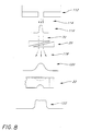
- FIG. 8 is a schematic drawing illustrating the various beam profiles within the proton beam scattering system.
- a control room computer 10 is in direct communication with an embedded computer 12 and a controller 14.
- the controller 14 and the embedded computer 12 transmit the appropriate signals to a source 16 and a motor and position control unit 18, respectively.
- the motor and position control unit 18, controls the positioning of a first scatterer 20.
- the first scatterer 20, in combination with a second scatterer 22, make up one embodiment of a scattering system 24, which scatters a beam 26 of particles emitted by the source 16.
- the resulting beam 26 of particles is shaped by a patient collimator 23, partially absorbed by a bolus 28, and impinges on a specified target 30 area located in a patient.
- the source 16 comprises an accelerator, such as a synchrotron, that accelerates charged subatomic particles to energies which are useful for radiation treatment therapy.
- the synchrotron comprises a ring of energized magnets which produce a magnetic field. Particles, particularly protons, travel through the magnets in a vacuum tube. As the magnetic field in the ring is increased, the energy of the circulating protons also increases. The magnetic field continues to increase until it reaches a value which corresponds to a prescribed proton beam energy. At this point, the magnetic field is held constant and the protons are slowly extracted from the synchrotron.
- the energy range for a patient treatment may be, for example, a minimum of 70 MeV to a maximum energy of 250 MeV.
- the synchrotron is capable of accelerating protons to 70 MeV in one-quarter second and to 250 MeV in one-half second. The protons are emitted from the synchrotron in a gaussian-shaped beam.
- a treatment planning computer 11 is used to plan a specific treatment necessary for each individual patient and provide the information used by the proton beam therapy device 80 during the patient treatment.
- the information is transferred from the treatment planning computer 11 to the control room computer 10 prior to delivering the radiation used in the patient's treatment. After being processed by the control room computer 10, the information is then sent to the embedded computer 12 and the controller 14.
- the controller 14 receives the signals sent from the control room computer 10 and adjusts various accelerator parameters, such as the magnetic field of the magnets in the synchrotron, until the desired, corresponding proton beam energy is obtained.
- various accelerator parameters such as the magnetic field of the magnets in the synchrotron
- the controller 14 has the ability to increase or decrease proton acceleration via the ring of magnets.
- the controller 14 monitors the status of the source 16 and sends this information to the control room computer 10, which ultimately determines whether or not to terminate proton beam delivery.
- the embedded computer 12 also receives commands from the control room computer and directly communicates this information to the motor and position control unit 18, shown in FIGURE 2, which primarily controls the positioning of the first scatterer 20.
- the function of the embedded computer 12 is to continuously check the position of the first scatterer 20 via the motor and position control unit 18 and a verification encoder 32.
- the embedded computer 12 has the ability to terminate patient treatment by way of the control room computer 10 when the first scatterer 20 is no longer properly positioned.
- FIGURE 2 shows one embodiment of the motor and position control unit 18 and the first scatterer 20.
- the embedded computer 12 is in direct communication with the motor and position control unit 18 and the verification encoder 32.
- the motor and position control unit 18 receives information from the embedded computer 12 and transmits the appropriate signals to a motor 34, that simultaneously rotates two identical shafts 36,38. Since the shafts 36,38 are identical, the following description will reference only the first shaft 36.
- a coupling 40 connects a bracket 42 to a shaft 36.
- a wedge 46, mounted on the bracket 42 is comprised of a scattering material 50 housed in a frame 52.
- a position encoder 56 monitors the position of a first wedge 46 via the number of rotations of the shaft 36 and sends the appropriate signals to the motor and position control unit 18.
- the motor and position control unit 18 relays this information to the embedded computer 12, which verifies that the position of the first scatterer 20 is correct.
- the verification encoder 32 similar to the position encoder 56, verifies the position of a second wedge 48 by way of counting the number of rotations of the shaft 38, but relays this information directly to the embedded computer 12.
- the shafts 36,38 are configured as cylindrical rods comprising a threaded section 58 and a non-threaded section 60.
- the threaded section 58 of each shaft 36,38 is incised with external continuous helical ribs or threads.
- the pitch of thread which is measured in terms of the number of threads (or grooves) per unit of axial length, is identical on both shafts 36,38.
- a distal end 62 of the first shaft 36 extends into the position encoder 56, whereas a distal end 64 of the second shaft 38 extends into the verification encoder 32.
- a proximal end 66 of both shafts 36,38 extend into the motor 34.
- Each shaft 36,38 is precisely made to provide a given linear displacement to each coupling 40 for each revolution.
- the spiral threads on each shaft 36,38 equally convert the rotary motion from the motor 34 into a linear movement of the couplings 40, which, subsequently, move the wedges 46,48 in unison.
- the motor and position control unit 18 controls the motor 34 rotations so that equivalent sections of the wedges 46,48 overlap, thereby presenting a uniform wedge thickness at the beam intercept portion 70, as shown in FIGURE 4.
- each wedge 46,48 comprises five flat or planar surfaces 68.
- Three of the surfaces 68a,68b,68c are four-sided or rectangular in shape, each side forming a 90° angle with its adjacent side; and, two of the surfaces 68d,68e are three-sided or triangular in shape, each triangular shaped surface having one 90° angle.
- Two of the rectangular shaped surfaces 68b,68c are at a 90° angle to each other, one surface 68c being in a plane parallel to the direction of motion 74, herewith designated as a parallel surface 68c, and the other surface 68b being in a plane orthogonal to the direction of motion 74, herewith designated as an orthogonal surface 68b.
- inclined means relative to the direction of movement 74 of the wedges.
- Each wedge is made of a high z-material, such as lead.
- a high z-material contains high atomic number atoms that generate scattering but do not change the energy of the particles.
- the wedges 46,48 are positioned so that their inclined surfaces 68a extend in opposite directions.
- the parallel surface 68c of the first wedge 46 lies in a plane parallel to a plane in which lies the parallel surface 68c of the second wedge 48.
- These planes, containing the wedges 46,48, are, thus, also parallel to the direction of motion 74 of the wedges 46,48.
- An air gap 72 extends between the first wedge 46 and the second wedge 48.
- the wedges 46,48 are aligned so that the entire beam intercept portion 70 is of equal and uniform thickness of air gap 72 and scattering material 50. Thus, the wedges 46,48 may travel their entire length of motion/travel without colliding.
- each coupling 40 travels the entire length of the threaded section 58 of the shaft onto which it is mounted.
- the threaded sections 58 are longer than the length of the non-inclined rectangular surfaces 68c of the wedges so that, when the couplings 40 are located at a threaded, distal end 76 of the shafts 36,38, the wedges 46,48 are positioned so that they do not overlap and no scattering material 50 is in the beam path 70. With the wedges in this position, no scattering occurs at the first scatterer 20. In contrast, the thickest amount of scattering material 50 is in the beam path 70 when frames 52 are adjacent to, but not within, the beam path 70.
- the couplings 40 are located at a threaded, proximal end 78 of the shafts 36,38.
- This particular configuration produces the greatest amount of scattering at the first scatterer 20.
- the couplings 40 are located at some intermediate position on the threaded portion of the shafts 36,38, there is an intermediate amount of scattering material in the beam path and, consequently, an intermediate amount of scattering of the proton beam.
- an infinite choice of scattering material 50 thicknesses is available. Regardless of the choice, the combined thickness of the material 50 in the beam intercept portion 70 will be uniform. Due to this alignment and configuration of the first scatterer 20, all beams emerging from the beam intercept portion 70 of the first scatterer 20, regardless of the amount of scattering produced, will possess a basically gaussian shape.
- the first scatterer 20, in combination with the second scatterer 22, comprises one embodiment of the scattering system 24 as shown in FIGURE 1.
- One embodiment for the second scatterer 22 of the scattering system 24 is shown in FIGURE 5.
- the wheel-shaped second scatterer 22 is comprised of a frusto-cylindrically shaped frame 90 housing a plurality of secondary scattering foils 92.
- Located in the center of the wheel-shaped second scatterer 22 is a rod 94. The rod 94 is used to mount the second scatterer 22 in the proton beam therapy device 80.
- the secondary scattering foils 92 are located equidistant from one another and from the rod 94.
- Each secondary scattering foil 92 is comprised of both high z material 82 and low z material 84.
- the high z material 82 has a cross-sectional profile that is substantially gaussian in shape and is disposed within a hollowed-out portion 86 of the low z material 84.
- the low z material 84 e.g. plastics made of carbon
- the hollowed-out portion 86 has a substantially gaussian shaped surface that corresponds to the gaussian shaped profile of the high z material 82.
- the second scatterer 22 is rotated around the rod 94 so that a different secondary scattering foil 92 is located in the path of the proton beam 26.
- FIGURE 5 is one embodiment of the second scatterer; however, other suitable forms of the second scatterer, such as a second scatterer comprising six secondary scattering foils, may be suitable for some applications.
- each secondary scattering foil 92 has a different configuration of high z material 82 and low z material 84.
- one configuration of the secondary scattering foil 92 may include a large substantially gaussian shaped high z material 82, whereas another configuration may include a smaller substantially gaussian shaped high z material 82.
- the hollowed out portion of the low z material 82 may also be varied.
- one configuration of the low z material 82 may include a large substantially gaussian shaped hollowed out portion, whereas another configuration may include a smaller substantially gaussian shaped hollowed out portion.
- the type of low z material 82 and high z material 84 may also be varied to obtain various proton scattering configurations.
- a user may choose gold for a high z material 84 for one secondary scattering foil 92 and lead for the high z material 84 for another secondary scattering foil 92.
- the shape, amount and type of low z material 82 and high z material 84 may be varied to obtain numerous proton beam scattering configurations.
- the proton beam therapy system also may include a patient collimator 23 and a bolus 28.
- the patient collimator 23 may be comprised of a thick plate made of lead alloy and an aperture with a periphery that shapes the cross section of the beam to match the configuration of target 30.
- a bolus such as the bolus 28, is a mass of material, usually plastic, that is configured in accordance with the irregular three-dimensional shape of the patient's tumor and anatomy.
- the bolus 28 is used to vary the penetration range of the particles within the particle beam 26 as a function of the radial distance of the particles from the propagation axis of the beam 26. After emerging from the bolus 28, the beam of particles 26 impinges on the target 30, which is the site of the tumor in the patient.
- a particular patient may receive the proton beam therapy treatment in sequential segments that comprise various combinations of parameters and these segments could be discrete (with intervals of time therebetween) or continuous.
- parameters that may vary from one segment to the next include beam range, scatterer thickness, field radius and proton beam energy.
- Beam range refers to the depth of proton beam penetration into a patient, which may vary, depending on the treatment.
- the scatterer thickness refers to the thickness of the first scatterer 20 at the location where the beam 26 intercepts the scattering material 50, hereafter called the "beam intercept portion" 70.
- Field radius refers to the radius of the proton beam at a specified depth within the patient for a particular treatment.
- Proton beam energy refers to the energy of protons required to reach a specified depth within the patient at the target site.
- This information, beam range, scatterer thickness, field radius and proton beam energy, is determined for each segment of proton beam therapy treatment.
- the treatment planning computer determines the desired beam radii and range of beam penetration required for a specific target volume site, as shown in activity block 96.
- the treatment planning computer 11 takes these values, and using a previously stored table of values, interpolates them to obtain the scatterer thicknesses and proton beam energies required for each segment of the treatment, as shown in activity block 98.
- This information is then sent to the control room computer 10 which, during treatment, relays the values to the controller 14 and the embedded computer 12 so that the appropriate signals are sent to adjust the energy emitted from the source 16 and the thickness of the first scatter 20, respectively, as shown in activity block 100.
- the energy from the source 16 and the position of the first scatter 20 are verified, as shown in activity block 102, and, if incorrect, treatment is terminated, as shown in activity block 104.
- the beam energy and scatterer position are correct, the beam is enabled and the treatment segment is delivered to the target, as shown in activity block 106.
- the system checks if there are additional segments, as shown in activity block 108. If additional segments exist, the appropriate values for the next segment are retrieved and the process is repeated. However, if no additional segments exist, treatment is terminated, as shown in activity block 110.
- FIGURE 8 The shape of the proton beam energy distribution at various locations within the proton beam therapy system is illustrated in FIGURE 8.
- Protons are generated by the accelerator and pass through a beam collimator 112, located immediately upstream of the wedges.
- the beam of protons 114 coming out of the collimator 112 has a narrow cross sectional width.
- the beam 114 passes through the beam intercept portion of the first scatterer 20.
- the beam intercept portion 70 of the first scatterer 20 presents a uniform thickness of material over the entire area of the proton beam 114. Due to the particular configuration and material composition of the first scatterer 20, the scattered beam of protons 118 obtains a nearly gaussian fluence profile 120.
- the first scatterer 20 has increased the beam 114 diameter but the beam intensity is not uniform over the entire beam area. Further scattering of the beam 118 occurs as a result of passing through the second scatterer 22. Due to the particular design and material composition of the second scatterer 22, the profile of the beam 118 broadens and has a uniform range and uniform fluence profile 122. Thus, the diameter of the proton beam has been expanded to cover a substantial portion of the treatment field, while maintaining beam uniformity.
- an operator mounts into the proton beam therapy device the bolus 28 corresponding to the three-dimensional shape of the patient's tumor.
- the bolus 28 is located between the second scatterer 22 and the patient/target 30.
- the scattering thicknesses and proton beam energy are obtained from the treatment planning computer for each of the various treatment segments. This information is then downloaded to the embedded computer 12 and the controller 14.
- the controller 14 adjusts the source 16 until the appropriate proton beam energy is achieved.
- the embedded computer 12 sends the appropriate signals to the motor and position control unit 18 to properly position and verify the location of the wedges 46,48.
- the proper position corresponds to the required thickness in the beam intercept portion 70 of the first scatterer 20.
- the motor and position control unit 18 adjusts the first scatterer 20 until properly positioned and the desired thickness achieved.
- the source 16 and the motor and position control unit 18 sends back signals to the controller 14 and the embedded computer 12, respectively. If the appropriate beam energy and scatterer thickness are not achieved, the embedded computer 12 and the controller 14 sends a signal to the control room computer 10 to terminate the treatment. If, however, the signals from the embedded computer 12 and the controller 14 corresponded to information that the source 10 is at the appropriate energy level and the wedges 46,48 are properly positioned, the proton beam is enabled and treatment initiated.
- the proton beam therapy system After delivering the first treatment segment, the proton beam therapy system makes the appropriate adjustments to the beam energy and first scatterer thickness, if necessary, so the next treatment segment may be initiated. After all the segments have been delivered, treatment is terminated and the proton beam disabled.
Landscapes
- Health & Medical Sciences (AREA)
- Engineering & Computer Science (AREA)
- Biomedical Technology (AREA)
- General Health & Medical Sciences (AREA)
- Nuclear Medicine, Radiotherapy & Molecular Imaging (AREA)
- Radiology & Medical Imaging (AREA)
- Life Sciences & Earth Sciences (AREA)
- Animal Behavior & Ethology (AREA)
- Pathology (AREA)
- Public Health (AREA)
- Veterinary Medicine (AREA)
- Radiation-Therapy Devices (AREA)
- Tents Or Canopies (AREA)
- Vehicle Step Arrangements And Article Storage (AREA)
- Treatments Of Macromolecular Shaped Articles (AREA)
- Physical Or Chemical Processes And Apparatus (AREA)
Abstract
Description
- The present invention is related to a radiation treatment apparatus utilizing scattering to produce a continuously variable penetration radiation beam.
- Such a radiation treatment apparatus is known from JP 63/249 578 A disclosing the pre-characterizing features of
present claim 1. - Conventional radiation therapy utilizes electron beams and x-rays as a means of treating and controlling cancer. Due to the inability of current technology to preferentially deposit the radiation at the site of the cancer, healthy tissues between the tissue surface and the cancer also receive high doses of radiation and, thus, are damaged. Consequently, physicians use a less-than-optimal dose to reduce the undesirable damage to healthy tissues and the subsequent side effects. In many cases, this proves to be an unacceptable alternative.
- Proton therapy has proven to be a viable alternative to x-ray and electron beam therapy in cancer treatment. By offering greater precision than conventional radiation therapy, physicians are able to deliver higher, more effective doses to target volumes. Protons tend to travel through the body tissue without significant absorption until they reach a specific point within the body. At this point, which corresponds to the Bragg peak of the proton beam, the proton energy is released. Accordingly, when the Bragg peak of the proton beam corresponds with the target location to be treated, the target location receives the highest concentration of radiation. There is very little lateral secondary scatter and, thus, virtually no damage to surrounding healthy tissues. While the Bragg peak for monoenergetic proton beams permits the energy deposited by the beam to be concentrated at a particular site within the patient, the proton beam is typically only a few millimeters wide, which is insufficient for delivering a sufficient radiation treatment dose to irregularly-shaped three-dimensional treatment volumes, such as tumors, particularly if the treatment volumes are large.
- Thus, there is a need for a radiation treatment system which will accurately and reproducibly deliver maximum, uniform radiation treatment to designated target volumes.
- The present invention as claimed provides a novel scattering system for charged particles which allows depth dose tailoring using spill to spill energy extraction while maintaining field uniformity. The claimed invention includes a source of charged particles which produces a beam of charged particles. A scattering foil is placed in the path of the particle beam for changing the diameter of the particle beam and, thereby, covering the target volume.
- The beam intercept portion of the scattering foil provides a uniform thickness which is continuously adjustable through a range of thicknesses. Preferably, the scattering system is comprised of first and second scatterers. The first scatterer is comprised of a pair of parallel and opposing tapered wedges. The wedges are made of the high z material (e.g. lead, gold, ...), which contains high atomic number atoms that generate scattering but do not change the energy (i.e. do not significantly change the range). Each wedge slides back and forth on rails or shafts and is controlled by a motor and position control unit, so that equivalent sections of the wedges overlap at the beam intercept portion.
- The second scatterer is mounted on a carousel and intercepts the path of the particle beam at a location downstream from the first scatterer. The second scattering foil is made of both high z material and low z material. The low z material (e.g. plastics made of carbon) contains low atomic number atoms that do not generate much scattering but do reduce the energy. The high atomic number material has a cross-sectional profile that is approximately gaussian in shape. The low atomic number material surrounds the high atomic number material and, directly beneath it, has a hollowed-out portion which has a mating profile that is approximately gaussian in shape.
- The invention also includes a controller which adjusts the energy of the particles in the beam at the source. In addition, a patient collimator and a bolus, configured to the irregular three-dimensional shape of the tumor, is used to vary the penetration range of the particles within the particle beam as a function of the radial distance of the particles from the propagation axis of the beam.
- During operation of this scattering system, the protons are generated by the source, a particle accelerator, typically a synchrotron, and impinge onto the first scatterer. After being scattered by the wedges, the proton beam has a nearly gaussian fluence profile. The first scatterer, therefore, provides only part of the total scattering needed, the rest being provided by the second scatterer. The beam emerging from the second scatterer is broad at the patient location with both a uniform range and a uniform fluence profile.
- FIG. 1 is a schematic view of the charged particle beam therapy system.
- FIG. 2 is a partially schematic plan view of the motor and position control unit and the first scatterer.
- FIG. 3 is a perspective view illustrating one of the wedges of the first scatterer.
- FIG. 4 is an elevational view in partial cross section taken along the lines 4-4 of Fig. 2 showing the wedges of the first scatterer.
- FIG. 5 is a plan view showing plural secondary scattering foils mounted in a carousel.
- FIG. 6 is an elevation view in partial cross section taken along the lines 6-6 of Fig. 5 showing the plural secondary scattering foils.
- FIG. 7 is a flow chart illustrating the operation of the proton beam scattering system.
- FIG. 8 is a schematic drawing illustrating the various beam profiles within the proton beam scattering system.
- Referring to FIGURE 1, in the preferred embodiment of the invention, a
control room computer 10 is in direct communication with an embeddedcomputer 12 and acontroller 14. Thecontroller 14 and the embeddedcomputer 12 transmit the appropriate signals to asource 16 and a motor andposition control unit 18, respectively. The motor andposition control unit 18, in turn, controls the positioning of afirst scatterer 20. Thefirst scatterer 20, in combination with asecond scatterer 22, make up one embodiment of ascattering system 24, which scatters abeam 26 of particles emitted by thesource 16. Finally, theresulting beam 26 of particles is shaped by apatient collimator 23, partially absorbed by abolus 28, and impinges on a specifiedtarget 30 area located in a patient. - The
source 16 comprises an accelerator, such as a synchrotron, that accelerates charged subatomic particles to energies which are useful for radiation treatment therapy. The synchrotron comprises a ring of energized magnets which produce a magnetic field. Particles, particularly protons, travel through the magnets in a vacuum tube. As the magnetic field in the ring is increased, the energy of the circulating protons also increases. The magnetic field continues to increase until it reaches a value which corresponds to a prescribed proton beam energy. At this point, the magnetic field is held constant and the protons are slowly extracted from the synchrotron. The energy range for a patient treatment may be, for example, a minimum of 70 MeV to a maximum energy of 250 MeV. The synchrotron is capable of accelerating protons to 70 MeV in one-quarter second and to 250 MeV in one-half second. The protons are emitted from the synchrotron in a gaussian-shaped beam. - A
treatment planning computer 11 is used to plan a specific treatment necessary for each individual patient and provide the information used by the protonbeam therapy device 80 during the patient treatment. The information is transferred from thetreatment planning computer 11 to thecontrol room computer 10 prior to delivering the radiation used in the patient's treatment. After being processed by thecontrol room computer 10, the information is then sent to the embeddedcomputer 12 and thecontroller 14. - The
controller 14 receives the signals sent from thecontrol room computer 10 and adjusts various accelerator parameters, such as the magnetic field of the magnets in the synchrotron, until the desired, corresponding proton beam energy is obtained. Thus, thecontroller 14 has the ability to increase or decrease proton acceleration via the ring of magnets. In addition, thecontroller 14 monitors the status of thesource 16 and sends this information to thecontrol room computer 10, which ultimately determines whether or not to terminate proton beam delivery. - The embedded
computer 12 also receives commands from the control room computer and directly communicates this information to the motor andposition control unit 18, shown in FIGURE 2, which primarily controls the positioning of thefirst scatterer 20. Thus, the function of the embeddedcomputer 12 is to continuously check the position of thefirst scatterer 20 via the motor andposition control unit 18 and averification encoder 32. In addition, the embeddedcomputer 12 has the ability to terminate patient treatment by way of thecontrol room computer 10 when thefirst scatterer 20 is no longer properly positioned. - FIGURE 2 shows one embodiment of the motor and
position control unit 18 and thefirst scatterer 20. In this embodiment, the embeddedcomputer 12 is in direct communication with the motor andposition control unit 18 and theverification encoder 32. The motor andposition control unit 18 receives information from the embeddedcomputer 12 and transmits the appropriate signals to amotor 34, that simultaneously rotates twoidentical shafts shafts first shaft 36. Acoupling 40 connects abracket 42 to ashaft 36. Awedge 46, mounted on thebracket 42, is comprised of ascattering material 50 housed in aframe 52. Aposition encoder 56 monitors the position of afirst wedge 46 via the number of rotations of theshaft 36 and sends the appropriate signals to the motor andposition control unit 18. Next, the motor andposition control unit 18 relays this information to the embeddedcomputer 12, which verifies that the position of thefirst scatterer 20 is correct. Theverification encoder 32, similar to theposition encoder 56, verifies the position of asecond wedge 48 by way of counting the number of rotations of theshaft 38, but relays this information directly to the embeddedcomputer 12. - The
shafts section 58 and anon-threaded section 60. The threadedsection 58 of eachshaft shafts distal end 62 of thefirst shaft 36 extends into theposition encoder 56, whereas a distal end 64 of thesecond shaft 38 extends into theverification encoder 32. Aproximal end 66 of bothshafts motor 34. - Each
shaft coupling 40 for each revolution. Thus, the spiral threads on eachshaft motor 34 into a linear movement of thecouplings 40, which, subsequently, move thewedges position control unit 18 controls themotor 34 rotations so that equivalent sections of thewedges beam intercept portion 70, as shown in FIGURE 4. - Referring to FIGURE 3, for this embodiment, each
wedge planar surfaces 68. Three of thesurfaces surfaces surfaces surface 68c being in a plane parallel to the direction ofmotion 74, herewith designated as aparallel surface 68c, and theother surface 68b being in a plane orthogonal to the direction ofmotion 74, herewith designated as anorthogonal surface 68b. The remaining rectangular shaped surface 68a forms an inclined plane and is designated an inclined surface 68a. For this embodiment and for all intents and purposes, inclined means relative to the direction ofmovement 74 of the wedges. Each wedge is made of a high z-material, such as lead. A high z-material contains high atomic number atoms that generate scattering but do not change the energy of the particles. - Referring to FIGURE 4, the
wedges parallel surface 68c of thefirst wedge 46 lies in a plane parallel to a plane in which lies theparallel surface 68c of thesecond wedge 48. These planes, containing thewedges motion 74 of thewedges air gap 72, of constant thickness, extends between thefirst wedge 46 and thesecond wedge 48. Thewedges beam intercept portion 70 is of equal and uniform thickness ofair gap 72 and scatteringmaterial 50. Thus, thewedges - Referring back to FIGURE 2, each
coupling 40 travels the entire length of the threadedsection 58 of the shaft onto which it is mounted. The threadedsections 58 are longer than the length of the non-inclinedrectangular surfaces 68c of the wedges so that, when thecouplings 40 are located at a threaded,distal end 76 of theshafts wedges material 50 is in thebeam path 70. With the wedges in this position, no scattering occurs at thefirst scatterer 20. In contrast, the thickest amount of scatteringmaterial 50 is in thebeam path 70 when frames 52 are adjacent to, but not within, thebeam path 70. In this position, thecouplings 40 are located at a threaded,proximal end 78 of theshafts first scatterer 20. When thecouplings 40 are located at some intermediate position on the threaded portion of theshafts first scatterer 20, an infinite choice of scatteringmaterial 50 thicknesses is available. Regardless of the choice, the combined thickness of the material 50 in thebeam intercept portion 70 will be uniform. Due to this alignment and configuration of thefirst scatterer 20, all beams emerging from thebeam intercept portion 70 of thefirst scatterer 20, regardless of the amount of scattering produced, will possess a basically gaussian shape. - The
first scatterer 20, in combination with thesecond scatterer 22, comprises one embodiment of thescattering system 24 as shown in FIGURE 1. Thesecond scatterer 22, while not essential to the scattering system, is typically preferred under normal operating conditions in a protonbeam therapy device 80. One embodiment for thesecond scatterer 22 of thescattering system 24 is shown in FIGURE 5. For this embodiment, the wheel-shapedsecond scatterer 22 is comprised of a frusto-cylindrically shapedframe 90 housing a plurality of secondary scattering foils 92. Located in the center of the wheel-shapedsecond scatterer 22 is arod 94. Therod 94 is used to mount thesecond scatterer 22 in the protonbeam therapy device 80. The secondary scattering foils 92 are located equidistant from one another and from therod 94. Eachsecondary scattering foil 92 is comprised of bothhigh z material 82 andlow z material 84. Referring to FIGURE 6, thehigh z material 82 has a cross-sectional profile that is substantially gaussian in shape and is disposed within a hollowed-out portion 86 of thelow z material 84. The low z material 84 (e.g. plastics made of carbon) contains low atomic number atoms that do not generate much scattering but do reduce the energy of each of the protons in the proton beam. The hollowed-out portion 86 has a substantially gaussian shaped surface that corresponds to the gaussian shaped profile of thehigh z material 82. In order to change the beam shape (i.e., profile of energy distribution) or amount of scatter from thesecondary scattering foil 92, thesecond scatterer 22 is rotated around therod 94 so that a differentsecondary scattering foil 92 is located in the path of theproton beam 26. Thus, FIGURE 5 is one embodiment of the second scatterer; however, other suitable forms of the second scatterer, such as a second scatterer comprising six secondary scattering foils, may be suitable for some applications. - To obtain a plurality of proton beam scattering configurations, each
secondary scattering foil 92 has a different configuration ofhigh z material 82 andlow z material 84. For example, one configuration of thesecondary scattering foil 92 may include a large substantially gaussian shapedhigh z material 82, whereas another configuration may include a smaller substantially gaussian shapedhigh z material 82. In addition to changing the amount ofhigh z material 84, the hollowed out portion of thelow z material 82 may also be varied. For example, one configuration of thelow z material 82 may include a large substantially gaussian shaped hollowed out portion, whereas another configuration may include a smaller substantially gaussian shaped hollowed out portion. Alternatively, the type oflow z material 82 andhigh z material 84 may also be varied to obtain various proton scattering configurations. For example, a user may choose gold for ahigh z material 84 for onesecondary scattering foil 92 and lead for thehigh z material 84 for anothersecondary scattering foil 92. Thus, the shape, amount and type oflow z material 82 andhigh z material 84 may be varied to obtain numerous proton beam scattering configurations. - Referring back to FIGURE 1, the proton beam therapy system also may include a
patient collimator 23 and abolus 28. Thepatient collimator 23 may be comprised of a thick plate made of lead alloy and an aperture with a periphery that shapes the cross section of the beam to match the configuration oftarget 30. As is well known, a bolus, such as thebolus 28, is a mass of material, usually plastic, that is configured in accordance with the irregular three-dimensional shape of the patient's tumor and anatomy. Thebolus 28 is used to vary the penetration range of the particles within theparticle beam 26 as a function of the radial distance of the particles from the propagation axis of thebeam 26. After emerging from thebolus 28, the beam ofparticles 26 impinges on thetarget 30, which is the site of the tumor in the patient. - Operation of the proton beam therapy system is best illustrated in FIGURE 7. During operation, a particular patient may receive the proton beam therapy treatment in sequential segments that comprise various combinations of parameters and these segments could be discrete (with intervals of time therebetween) or continuous. In any given treatment, parameters that may vary from one segment to the next include beam range, scatterer thickness, field radius and proton beam energy. Beam range refers to the depth of proton beam penetration into a patient, which may vary, depending on the treatment. The scatterer thickness refers to the thickness of the
first scatterer 20 at the location where thebeam 26 intercepts the scatteringmaterial 50, hereafter called the "beam intercept portion" 70. Field radius refers to the radius of the proton beam at a specified depth within the patient for a particular treatment. Proton beam energy refers to the energy of protons required to reach a specified depth within the patient at the target site. This information, beam range, scatterer thickness, field radius and proton beam energy, is determined for each segment of proton beam therapy treatment. Thus, for example, the treatment planning computer determines the desired beam radii and range of beam penetration required for a specific target volume site, as shown inactivity block 96. Thetreatment planning computer 11 takes these values, and using a previously stored table of values, interpolates them to obtain the scatterer thicknesses and proton beam energies required for each segment of the treatment, as shown inactivity block 98. This information is then sent to thecontrol room computer 10 which, during treatment, relays the values to thecontroller 14 and the embeddedcomputer 12 so that the appropriate signals are sent to adjust the energy emitted from thesource 16 and the thickness of thefirst scatter 20, respectively, as shown inactivity block 100. Next, the energy from thesource 16 and the position of thefirst scatter 20 are verified, as shown inactivity block 102, and, if incorrect, treatment is terminated, as shown inactivity block 104. However, if the beam energy and scatterer position are correct, the beam is enabled and the treatment segment is delivered to the target, as shown inactivity block 106. After the segment has been delivered, the system checks if there are additional segments, as shown inactivity block 108. If additional segments exist, the appropriate values for the next segment are retrieved and the process is repeated. However, if no additional segments exist, treatment is terminated, as shown inactivity block 110. - The shape of the proton beam energy distribution at various locations within the proton beam therapy system is illustrated in FIGURE 8. Protons are generated by the accelerator and pass through a
beam collimator 112, located immediately upstream of the wedges. The beam ofprotons 114 coming out of thecollimator 112 has a narrow cross sectional width. Upon exiting thecollimator 112, thebeam 114 passes through the beam intercept portion of thefirst scatterer 20. Thebeam intercept portion 70 of thefirst scatterer 20 presents a uniform thickness of material over the entire area of theproton beam 114. Due to the particular configuration and material composition of thefirst scatterer 20, the scattered beam ofprotons 118 obtains a nearlygaussian fluence profile 120. Thus, thefirst scatterer 20 has increased thebeam 114 diameter but the beam intensity is not uniform over the entire beam area. Further scattering of thebeam 118 occurs as a result of passing through thesecond scatterer 22. Due to the particular design and material composition of thesecond scatterer 22, the profile of thebeam 118 broadens and has a uniform range anduniform fluence profile 122. Thus, the diameter of the proton beam has been expanded to cover a substantial portion of the treatment field, while maintaining beam uniformity. - Referring again to FIGURE 1, during operation of the proton beam therapy system, an operator mounts into the proton beam therapy device the
bolus 28 corresponding to the three-dimensional shape of the patient's tumor. Thebolus 28 is located between thesecond scatterer 22 and the patient/target 30. The scattering thicknesses and proton beam energy are obtained from the treatment planning computer for each of the various treatment segments. This information is then downloaded to the embeddedcomputer 12 and thecontroller 14. - The
controller 14 adjusts thesource 16 until the appropriate proton beam energy is achieved. During this time, the embeddedcomputer 12 sends the appropriate signals to the motor andposition control unit 18 to properly position and verify the location of thewedges beam intercept portion 70 of thefirst scatterer 20. Thus, the motor andposition control unit 18 adjusts thefirst scatterer 20 until properly positioned and the desired thickness achieved. - Next, the
source 16 and the motor andposition control unit 18 sends back signals to thecontroller 14 and the embeddedcomputer 12, respectively. If the appropriate beam energy and scatterer thickness are not achieved, the embeddedcomputer 12 and thecontroller 14 sends a signal to thecontrol room computer 10 to terminate the treatment. If, however, the signals from the embeddedcomputer 12 and thecontroller 14 corresponded to information that thesource 10 is at the appropriate energy level and thewedges - After delivering the first treatment segment, the proton beam therapy system makes the appropriate adjustments to the beam energy and first scatterer thickness, if necessary, so the next treatment segment may be initiated. After all the segments have been delivered, treatment is terminated and the proton beam disabled.
Claims (19)
- A radiation treatment apparatus (80), comprising:a source (16) of charged particles which provides a charged particle beam (26,114); anda scattering foil (20,24) in the path of the particle beam (26,114), said beam intercepting said scattering foilat a beam intercept portion (70), said scattering foil being configured so that its thickness at said beam intercept portion (70) is continuously adjustable through a range of thicknesses, the thickness of said scattering foil being (20,24) uniform throughout said beam intercept portion (70) through said range of thicknesses, characterised in that said scattering foil is particularly adapted for changing the cross section of the particle beam (26,114) by being comprised of a high z material (50) such as lead or gold, which contains high atomic number atoms that generate scattering but do not significantly change the energy i.e. do not significantly change the penetration range.
- The apparatus of Claim 1, additionally comprising a controller (14) for adjusting the energy of the particles in said beam (26, 114).
- The apparatus of Claim 1, additionally comprising a controller (14) for adjusting the intensity of the beam (26,114).
- The apparatus of Claim 2, wherein said controller (14) varies the energy of the particles in said beam (26,114) at a location upstream of said scattering foil (20,24).
- The apparatus of Claim 4, wherein said controller (14) is connected to said source (16) so as to vary the energy of the particles in said beam (26,114) at said source (16).
- The apparatus of Claim 1, additionally comprising an embedded computer (12) which controls the thickness of said scattering foil (20,24).
- The apparatus of Claim 5, wherein said scattering foil (20,24) comprises a first scatterer (20) comprising a pair of wedges (46,48), and wherein the apparatus comprises an embedded computer (12) which is connected to drive said wedges (46,48) to vary the thickness of said scattering foil.
- The apparatus of Claim 1, wherein said scattering foil comprises a first scatterer (20) comprising a pair of wedges (46,48) each having a taper (68a).
- The apparatus of Claim 8, wherein said wedges (46,48) comprise lead.
- The apparatus of Claim 8, comprising a driver for relatively driving each of said wedges (46,48) in a direction of said taper (68a).
- The apparatus of Claim 10, additionally comprising a control room computer (10) connected to said controller (14) for adjusting the energy of the particles in said beam (26,114), said control room computer (10) connected to said driver to adjust the position of said wedges (46,48) in response to changes in the energy of the particles in said beam (26,114) such that said cross section of said beam is maintained substantially constant.
- The apparatus of Claim 10, additionally comprising an embedded computer (12) that controls the thickness of said scattering foil (20,24).
- The apparatus of Claim 2, additionally comprising a second scatterer (22) disposed in the path of said particle beam (26,114) at a location downstream of said scattering foil (20).
- The apparatus of Claim 13, wherein said second scatterer (22) is comprised of both a low z material (84) and a high z material (82), said second scatterer (22) being one of a plurality of second scatterers (92) mounted on a carousel (90,94).
- The apparatus of Claim 13, wherein the controller (14) varies the energy of the particles of said beam at a location upstream both of said scattering foil and said second scatterer (20,22).
- The apparatus of Claim 1, additionally comprising a patient collimator (23) with an aperture, said aperture having a periphery that shapes the beam laterally to the target (30).
- The apparatus of Claim 1, additionally comprising a bolus (28) configured to vary the penetration range of particles within the particle beam (26,114) as a function of the radial distance of the particles from the propagation axis of the beam (26).
- The apparatus of Claim 12, wherein said scattering foil and said second scatterer (20,22) are configured to produce a beam (26) which has a substantially uniform fluence in a plane perpendicular to the axis of propagation.
- The apparatus of Claim 1, wherein said charged particles consist essentially of protons.
Applications Claiming Priority (5)
| Application Number | Priority Date | Filing Date | Title |
|---|---|---|---|
| US8719693A | 1993-07-02 | 1993-07-02 | |
| US87196 | 1993-07-02 | ||
| US08/102,770 US5440133A (en) | 1993-07-02 | 1993-08-06 | Charged particle beam scattering system |
| PCT/US1994/007461 WO1995001207A2 (en) | 1993-07-02 | 1994-07-01 | Charged particle beam scattering system |
| US102770 | 1998-06-23 |
Publications (2)
| Publication Number | Publication Date |
|---|---|
| EP0740569A1 EP0740569A1 (en) | 1996-11-06 |
| EP0740569B1 true EP0740569B1 (en) | 2001-10-17 |
Family
ID=26776711
Family Applications (1)
| Application Number | Title | Priority Date | Filing Date |
|---|---|---|---|
| EP94921448A Expired - Lifetime EP0740569B1 (en) | 1993-07-02 | 1994-07-01 | Charged particle beam scattering system |
Country Status (5)
| Country | Link |
|---|---|
| EP (1) | EP0740569B1 (en) |
| JP (1) | JP3166085B2 (en) |
| AT (1) | ATE206948T1 (en) |
| DE (1) | DE69428714T2 (en) |
| WO (1) | WO1995001207A2 (en) |
Families Citing this family (10)
| Publication number | Priority date | Publication date | Assignee | Title |
|---|---|---|---|---|
| US5585642A (en) * | 1995-02-15 | 1996-12-17 | Loma Linda University Medical Center | Beamline control and security system for a radiation treatment facility |
| EP1378266A1 (en) * | 1996-08-30 | 2004-01-07 | Hitachi, Ltd. | Charged particle beam apparatus |
| JP5638606B2 (en) | 2010-12-27 | 2014-12-10 | 住友重機械工業株式会社 | Energy degrader and charged particle irradiation system including the same |
| DE102011109380B4 (en) * | 2011-08-04 | 2015-05-13 | Gsi Helmholtzzentrum Für Schwerionenforschung Gmbh | Improved energy modulator |
| US8644571B1 (en) | 2011-12-06 | 2014-02-04 | Loma Linda University Medical Center | Intensity-modulated proton therapy |
| US20140264065A1 (en) | 2013-03-15 | 2014-09-18 | Varian Medical Systems, Inc. | Energy degrader for radiation therapy system |
| US9884206B2 (en) | 2015-07-23 | 2018-02-06 | Loma Linda University Medical Center | Systems and methods for intensity modulated radiation therapy |
| JP6755208B2 (en) * | 2017-03-08 | 2020-09-16 | 住友重機械工業株式会社 | Charged particle beam therapy device |
| KR102577452B1 (en) * | 2021-07-21 | 2023-09-12 | 국립암센터 | Converting apparatus for converting treament beam for treating disease in subject |
| CN116347743B (en) * | 2023-02-06 | 2023-11-10 | 散裂中子源科学中心 | Diffuser for extracting extremely weak particle beams |
Family Cites Families (2)
| Publication number | Priority date | Publication date | Assignee | Title |
|---|---|---|---|---|
| SE390697B (en) * | 1974-04-10 | 1977-01-17 | Scandiatronix Instr Ab | DEVICE FOR THE EFFECT OF ENERGY DISTRIBUTION AND SPATIAL DISTRIBUTION OF HOGENERGETIC PARTICULATE RADIATION WHEN IRRADIZING A LIMITED VOLUME |
| JPS63249578A (en) * | 1987-04-03 | 1988-10-17 | 三菱電機株式会社 | Flight destance controller |
-
1994
- 1994-07-01 EP EP94921448A patent/EP0740569B1/en not_active Expired - Lifetime
- 1994-07-01 WO PCT/US1994/007461 patent/WO1995001207A2/en not_active Ceased
- 1994-07-01 DE DE69428714T patent/DE69428714T2/en not_active Expired - Lifetime
- 1994-07-01 AT AT94921448T patent/ATE206948T1/en active
- 1994-07-01 JP JP50366695A patent/JP3166085B2/en not_active Expired - Lifetime
Also Published As
| Publication number | Publication date |
|---|---|
| JP3166085B2 (en) | 2001-05-14 |
| EP0740569A1 (en) | 1996-11-06 |
| DE69428714D1 (en) | 2001-11-22 |
| ATE206948T1 (en) | 2001-11-15 |
| WO1995001207A2 (en) | 1995-01-12 |
| JPH08511978A (en) | 1996-12-17 |
| WO1995001207A3 (en) | 1995-02-23 |
| DE69428714T2 (en) | 2002-05-08 |
Similar Documents
| Publication | Publication Date | Title |
|---|---|---|
| US5440133A (en) | Charged particle beam scattering system | |
| US8154001B2 (en) | Ion radiation therapy system with variable beam resolution | |
| US7295649B2 (en) | Radiation therapy system and method of using the same | |
| EP1541194B1 (en) | Particle beam irradiation system and method of adjusting irradiation field forming apparatus | |
| EP2280765B1 (en) | Treatment of patient tumors by charged particle therapy | |
| EP0904805B1 (en) | System for radiation therapy delivery | |
| CN1282400C (en) | Method for treating target volume with particle beam and device implementing same | |
| CN1298399C (en) | Rotation multielement radiation streaming forming device | |
| US5757881A (en) | Redundant field-defining arrays for a radiation system | |
| US5148032A (en) | Radiation emitting device with moveable aperture plate | |
| US7977657B2 (en) | Ion radiation therapy system with distal gradient tracking | |
| US6757355B1 (en) | High definition radiation treatment with an intensity modulating multi-leaf collimator | |
| JP4900610B2 (en) | Programmable particle scatterer for forming radiation therapy beams | |
| EP3331607B1 (en) | Radiation therapy with orthovoltage x-ray minibeams | |
| EP0905714A2 (en) | Dynamic sub-space intensity modulation | |
| US6687330B2 (en) | System and method for intensity modulated radiation therapy | |
| EP0740569A1 (en) | Charged particle beam scattering system | |
| JP2011050660A (en) | Particle beam medical treatment system and particle beam irradiation method | |
| JP6755208B2 (en) | Charged particle beam therapy device |
Legal Events
| Date | Code | Title | Description |
|---|---|---|---|
| PUAI | Public reference made under article 153(3) epc to a published international application that has entered the european phase |
Free format text: ORIGINAL CODE: 0009012 |
|
| 17P | Request for examination filed |
Effective date: 19960131 |
|
| AK | Designated contracting states |
Kind code of ref document: A1 Designated state(s): AT BE CH DE DK ES FR GB GR IE IT LI LU MC NL PT SE |
|
| 17Q | First examination report despatched |
Effective date: 19961104 |
|
| GRAG | Despatch of communication of intention to grant |
Free format text: ORIGINAL CODE: EPIDOS AGRA |
|
| GRAG | Despatch of communication of intention to grant |
Free format text: ORIGINAL CODE: EPIDOS AGRA |
|
| GRAG | Despatch of communication of intention to grant |
Free format text: ORIGINAL CODE: EPIDOS AGRA |
|
| GRAH | Despatch of communication of intention to grant a patent |
Free format text: ORIGINAL CODE: EPIDOS IGRA |
|
| GRAH | Despatch of communication of intention to grant a patent |
Free format text: ORIGINAL CODE: EPIDOS IGRA |
|
| RAP1 | Party data changed (applicant data changed or rights of an application transferred) |
Owner name: LOMA LINDA UNIVERSITY MEDICAL CENTER |
|
| RIN1 | Information on inventor provided before grant (corrected) |
Inventor name: SIEBERS, JEFFREY V. Inventor name: MOYERS, MICHAEL F. |
|
| RAP1 | Party data changed (applicant data changed or rights of an application transferred) |
Owner name: LOMA LINDA UNIVERSITY MEDICAL CENTER |
|
| GRAA | (expected) grant |
Free format text: ORIGINAL CODE: 0009210 |
|
| AK | Designated contracting states |
Kind code of ref document: B1 Designated state(s): AT BE CH DE DK ES FR GB GR IE IT LI LU MC NL PT SE |
|
| PG25 | Lapsed in a contracting state [announced via postgrant information from national office to epo] |
Ref country code: NL Free format text: LAPSE BECAUSE OF FAILURE TO SUBMIT A TRANSLATION OF THE DESCRIPTION OR TO PAY THE FEE WITHIN THE PRESCRIBED TIME-LIMIT Effective date: 20011017 |
|
| REF | Corresponds to: |
Ref document number: 206948 Country of ref document: AT Date of ref document: 20011115 Kind code of ref document: T |
|
| REG | Reference to a national code |
Ref country code: CH Ref legal event code: EP |
|
| REG | Reference to a national code |
Ref country code: IE Ref legal event code: FG4D |
|
| REG | Reference to a national code |
Ref country code: CH Ref legal event code: NV Representative=s name: ABATRON-PATENTBUERO AG |
|
| REF | Corresponds to: |
Ref document number: 69428714 Country of ref document: DE Date of ref document: 20011122 |
|
| REG | Reference to a national code |
Ref country code: GB Ref legal event code: IF02 |
|
| PG25 | Lapsed in a contracting state [announced via postgrant information from national office to epo] |
Ref country code: PT Free format text: LAPSE BECAUSE OF FAILURE TO SUBMIT A TRANSLATION OF THE DESCRIPTION OR TO PAY THE FEE WITHIN THE PRESCRIBED TIME-LIMIT Effective date: 20020117 Ref country code: DK Free format text: LAPSE BECAUSE OF FAILURE TO SUBMIT A TRANSLATION OF THE DESCRIPTION OR TO PAY THE FEE WITHIN THE PRESCRIBED TIME-LIMIT Effective date: 20020117 |
|
| PG25 | Lapsed in a contracting state [announced via postgrant information from national office to epo] |
Ref country code: GR Free format text: LAPSE BECAUSE OF FAILURE TO SUBMIT A TRANSLATION OF THE DESCRIPTION OR TO PAY THE FEE WITHIN THE PRESCRIBED TIME-LIMIT Effective date: 20020118 |
|
| ET | Fr: translation filed | ||
| NLV1 | Nl: lapsed or annulled due to failure to fulfill the requirements of art. 29p and 29m of the patents act | ||
| PG25 | Lapsed in a contracting state [announced via postgrant information from national office to epo] |
Ref country code: ES Free format text: LAPSE BECAUSE OF FAILURE TO SUBMIT A TRANSLATION OF THE DESCRIPTION OR TO PAY THE FEE WITHIN THE PRESCRIBED TIME-LIMIT Effective date: 20020430 |
|
| PG25 | Lapsed in a contracting state [announced via postgrant information from national office to epo] |
Ref country code: LU Free format text: LAPSE BECAUSE OF NON-PAYMENT OF DUE FEES Effective date: 20020701 Ref country code: IE Free format text: LAPSE BECAUSE OF NON-PAYMENT OF DUE FEES Effective date: 20020701 |
|
| PLBE | No opposition filed within time limit |
Free format text: ORIGINAL CODE: 0009261 |
|
| STAA | Information on the status of an ep patent application or granted ep patent |
Free format text: STATUS: NO OPPOSITION FILED WITHIN TIME LIMIT |
|
| 26N | No opposition filed | ||
| PG25 | Lapsed in a contracting state [announced via postgrant information from national office to epo] |
Ref country code: MC Free format text: LAPSE BECAUSE OF NON-PAYMENT OF DUE FEES Effective date: 20030201 |
|
| REG | Reference to a national code |
Ref country code: IE Ref legal event code: MM4A |
|
| PGFP | Annual fee paid to national office [announced via postgrant information from national office to epo] |
Ref country code: GB Payment date: 20130626 Year of fee payment: 20 |
|
| PGFP | Annual fee paid to national office [announced via postgrant information from national office to epo] |
Ref country code: CH Payment date: 20130712 Year of fee payment: 20 Ref country code: SE Payment date: 20130711 Year of fee payment: 20 Ref country code: DE Payment date: 20130626 Year of fee payment: 20 Ref country code: BE Payment date: 20130712 Year of fee payment: 20 Ref country code: AT Payment date: 20130626 Year of fee payment: 20 |
|
| PGFP | Annual fee paid to national office [announced via postgrant information from national office to epo] |
Ref country code: FR Payment date: 20130724 Year of fee payment: 20 |
|
| PGFP | Annual fee paid to national office [announced via postgrant information from national office to epo] |
Ref country code: IT Payment date: 20130712 Year of fee payment: 20 |
|
| REG | Reference to a national code |
Ref country code: DE Ref legal event code: R071 Ref document number: 69428714 Country of ref document: DE |
|
| REG | Reference to a national code |
Ref country code: DE Ref legal event code: R071 Ref document number: 69428714 Country of ref document: DE |
|
| REG | Reference to a national code |
Ref country code: CH Ref legal event code: PL |
|
| REG | Reference to a national code |
Ref country code: GB Ref legal event code: PE20 Expiry date: 20140630 |
|
| BE20 | Be: patent expired |
Owner name: *LOMA LINDA UNIVERSITY MEDICAL CENTER Effective date: 20140701 |
|
| PG25 | Lapsed in a contracting state [announced via postgrant information from national office to epo] |
Ref country code: GB Free format text: LAPSE BECAUSE OF EXPIRATION OF PROTECTION Effective date: 20140630 |
|
| REG | Reference to a national code |
Ref country code: AT Ref legal event code: MK07 Ref document number: 206948 Country of ref document: AT Kind code of ref document: T Effective date: 20140701 |
|
| REG | Reference to a national code |
Ref country code: SE Ref legal event code: EUG |
|
| PG25 | Lapsed in a contracting state [announced via postgrant information from national office to epo] |
Ref country code: DE Free format text: LAPSE BECAUSE OF EXPIRATION OF PROTECTION Effective date: 20140702 |