EP0740367A1 - A connector with a cap-type retainer - Google Patents
A connector with a cap-type retainer Download PDFInfo
- Publication number
- EP0740367A1 EP0740367A1 EP96302325A EP96302325A EP0740367A1 EP 0740367 A1 EP0740367 A1 EP 0740367A1 EP 96302325 A EP96302325 A EP 96302325A EP 96302325 A EP96302325 A EP 96302325A EP 0740367 A1 EP0740367 A1 EP 0740367A1
- Authority
- EP
- European Patent Office
- Prior art keywords
- connector
- retainer
- projections
- terminal fitting
- terminal
- Prior art date
- Legal status (The legal status is an assumption and is not a legal conclusion. Google has not performed a legal analysis and makes no representation as to the accuracy of the status listed.)
- Granted
Links
Images

Classifications
-
- H—ELECTRICITY
- H01—ELECTRIC ELEMENTS
- H01R—ELECTRICALLY-CONDUCTIVE CONNECTIONS; STRUCTURAL ASSOCIATIONS OF A PLURALITY OF MUTUALLY-INSULATED ELECTRICAL CONNECTING ELEMENTS; COUPLING DEVICES; CURRENT COLLECTORS
- H01R13/00—Details of coupling devices of the kinds covered by groups H01R12/70 or H01R24/00 - H01R33/00
- H01R13/40—Securing contact members in or to a base or case; Insulating of contact members
- H01R13/42—Securing in a demountable manner
- H01R13/436—Securing a plurality of contact members by one locking piece or operation
- H01R13/4364—Insertion of locking piece from the front
Definitions
- the present invention relates to a double-stopping connector, and particularly to a double-stopping electrical connector provided with a cap-type retainer.
- a female connector 1 comprises a housing 2, which has a main member 2a having terminal fitting insertion chambers 2a1 and a hood member 2b that envelops the main member 2a; a ring-shaped rubber seal 3 that fits within the hood member 2b; and a cap-shaped retainer 4 that is attachable to the front end of the main member 2a.
- the inner side face of the retainer 4 has terminal half-insertion detectors 4a formed thereon; these detectors 4a are inserted into the lower part of the terminal fitting insertion chambers 2a1 and can only be fully inserted if the terminal fitting is correctly installed; the detectors 4a thus indicate whether the terminal fittings are in a partly-inserted condition.
- One terminal half-insertion detector 4a is provided for each terminal fitting insertion chamber 2a1.
- four terminal half-insertion detectors 4a are formed for the corresponding terminal fitting insertion chambers 2a1 formed in an upper and lower row, and to the left and to the right.
- a slit 4b is formed in the retainer and a slit 2a2 is formed in the main member 2a in a vertical direction (as viewed) to allow insertion of a flat separation plate of a corresponding male connector.
- a conventional male connector 5 (Fig.1) comprises a housing 7 consisting of a base member 7a that supports male terminal fittings 6; a hood member 7b that surrounds the male terminal fittings 6 and that can be inserted into the hood member 2b; and a separation plate 7c that projects in the direction of the slits 4b and 2a2 and that serves to prevent contact between adjacent terminals.
- female terminal fittings 9 are inserted into the terminal fitting insertion chambers 2a1 of the main member 2a, and the ring-shaped rubber seal 3 is slipped on to the peripheral face of the main member 2a.
- the retainer 4 is attached from the front, the four terminal half-insertion detectors 4a are inserted into the lower parts of the terminal fitting insertion chambers 2a1. If the female terminal fittings 9 are not in a half-inserted position, the retainer 4 fits against the front portion of the main member 2a.
- the male connector 5 is inserted into the hood member 2b of the female connector 1.
- the separation plate 7c passes into the slits 4b and 2a2, and the male terminal fittings 6 pass through the retainer 4 and are engaged in the terminal fitting insertion chambers 2a1.
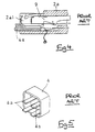
- Figure 4 illustrates the case where a terminal fitting 9 is not fully inserted.
- the conventional latching arm or lance 8 is unable to engage an aperture in the underside of the terminal, and thus remains in a downward condition where it obstructs proper entry of the half insertion detector 4a. It will be appreciated that when the lance is in the upper condition and the detector 4a fully inserted, the terminal is doubly stopped since the lance is locked against movement.
- each terminal half-insertion detector 4a projects for each terminal fitting insertion chamber 2a1, and as a result there is a problem that each terminal half-insertion detector 4a is relatively weak and easily broken.
- the present invention has been developed taking the above problem into consideration, and aims at presenting a double-stopping connector in which the terminal half-insertion detector can be strengthened.
- a retainer for a connector having a plurality of terminals engageable in sockets thereof, said retainer having two projections fully engageable in respective sockets of the connector when terminals of the sockets are correctly inserted, and not fully engageable when terminals of the sockets are not correctly inserted, characterised in that the projections are joined at the free ends thereof by a substantially orthogonal linking portion.
- the retainer is used in combination with a first connector comprising two terminal fitting insertion sockets for receiving respective terminal fittings in a terminal fitting insertion direction, said retainer being attachable to an end face of the housing and said sockets being connected by a slit adapted to receive said linking portion.
- a second connector engageable with the first connector has a locking plate for engagement with the first connector in the terminal fitting insertion direction; the second connector having a separation plate for engagement in the first connector, a through slit being formed in the retainer to receive the separation plate, and said separation plate passing between said projections and towards said linking portion.
- the cap-type retainer is attached to an end face of the first connector. Slits are formed in the retainer and the housing of the first connector to allow the insertion of the separation plate of the second connector.
- the projections of the retainer constitute half-insertion detectors that project into the terminal fitting insertion chambers of the first connector.
- the terminal half-insertion detectors are connected in pairs at the free ends, yet permit the insertion of the conventional separation plate. The terminal half-insertion detectors are thereby strengthened.
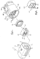
- FIGURE 1 is an exploded isometric view of a connector assembly relating to an embodiment of the present invention.
- FIGURE 2 is a schematic isometric view of the retainer of Fig.1 as seen from the rear.
- FIGURE 3 is an exploded isometric view of a prior art female water-proof connector using a conventional retainer.
- FIGURE 4 is a cross-sectional view through the housing of the female connector of Fig.3.
- FIGURE 5 is a schematic isometric view of the retainer of Fig.3 as seen from the rear.
- a female connector 10 comprises a tubular cavity member 21 which has terminal fitting insertion chambers 21a to the left and right and on an upper and lower level; a housing consisting of a tubular hood member 22 that surrounds this cavity member 21, a ring-shaped rubber seal 30 that can fit onto the external peripheral face of the cavity member 21, and a cap-shaped retainer 40 that can fit so as to cover the front end of the cavity member 21.
- Plate-shaped terminal half-insertion detectors 41 projecting from the rear face of the retainer 40 are insertable into portions formed on lower sides of the terminal fitting insertion chambers 21a located in the cavity member 21.
- the free ends of the terminal half-insertion detectors 41 on the left and right are mutually connected by a respective linking portion 44.
- the lower portions of the terminal fitting insertion chambers 21a to the left and right are mutually connected.
- a slit 21b is formed in an up-down direction (as viewed) in the cavity member 21 between the terminal fitting insertion chambers 21a provided to the left and right.
- the slit 21b extends into the terminal fitting insertion chambers 21a formed on both the upper and lower levels.
- a separation plate 7c located on the corresponding male connector 7.
- the retainer 40 In the retainer 40 are formed four terminal fitting insertion holes 42 facing the terminal fitting insertion chambers 21a. Furthermore, a slit 43 is formed between the terminal fitting insertion holes 42 located to the left and right. The slit 43 extends along the upper and lower levels where the terminal fitting insertion holes are located. The separation plate 7c of the male connector passes through this slit 43.
- the female connector 10 is provided with a housing 20 having a hood member 22 that surrounds the cavity 21.
- the hood member 22 may not be necessary.
- the rubber seal 30 is not indispensable.
- the male and female connectors are latched by a respective projection 31 and aperture 32 provided on a resilient arm 33.
- a latch is conventional and gives snap fitting engagement. Disengagement is by lifting the arm 33 and pulling the connector apart.
- female terminal fittings are inserted into each of the terminal fitting insertion chambers 21a and the rubber seal 30 is attached to the external periphery of the cavity member 21.
- the retainer 40 is attached to the outer end of the cavity member 21 and the ends of the terminal half-insertion detectors 41 are inserted fully into the corresponding cavity 21a of the terminal fittings are correctly installed.
- the separation plate passes through the slit 43 and into the slit 21b. Since the terminal half-insertion detectors 41 on the left and right mutually and independently project, insertion proceeds without interference.
- the terminal half-insertion detectors 41 are longer than the separation plate and remain connected inwardly of the plate. Accordingly, the connected portion of the detectors 41 does not interfere with the insertion of the separation plate. Compared to the conventional case where four individual terminal half-insertion detectors 41 are provided, the strength is increased.
Landscapes
- Connector Housings Or Holding Contact Members (AREA)
- Details Of Connecting Devices For Male And Female Coupling (AREA)
Abstract
Description
- The present invention relates to a double-stopping connector, and particularly to a double-stopping electrical connector provided with a cap-type retainer.
- Conventional double-stopping electrical connectors have provided a cap-type retainer that fits the front side of a tubular housing; this fitting direction constitutes the attachment direction for terminal fittings of the connector. Figures 3 to 5 of this specification show a conventional double stopping connector. A female connector 1 comprises a
housing 2, which has a main member 2a having terminal fitting insertion chambers 2a1 and ahood member 2b that envelops the main member 2a; a ring-shaped rubber seal 3 that fits within thehood member 2b; and a cap-shaped retainer 4 that is attachable to the front end of the main member 2a. As shown in Figures 4 and 5, the inner side face of theretainer 4 has terminal half-insertion detectors 4a formed thereon; thesedetectors 4a are inserted into the lower part of the terminal fitting insertion chambers 2a1 and can only be fully inserted if the terminal fitting is correctly installed; thedetectors 4a thus indicate whether the terminal fittings are in a partly-inserted condition. One terminal half-insertion detector 4a is provided for each terminal fitting insertion chamber 2a1. In the embodiment illustrated, four terminal half-insertion detectors 4a are formed for the corresponding terminal fitting insertion chambers 2a1 formed in an upper and lower row, and to the left and to the right. Furthermore, a slit 4b is formed in the retainer and a slit 2a2 is formed in the main member 2a in a vertical direction (as viewed) to allow insertion of a flat separation plate of a corresponding male connector. - A conventional male connector 5 (Fig.1) comprises a
housing 7 consisting of abase member 7a that supportsmale terminal fittings 6; ahood member 7b that surrounds themale terminal fittings 6 and that can be inserted into thehood member 2b; and aseparation plate 7c that projects in the direction of the slits 4b and 2a2 and that serves to prevent contact between adjacent terminals. - In use,
female terminal fittings 9 are inserted into the terminal fitting insertion chambers 2a1 of the main member 2a, and the ring-shaped rubber seal 3 is slipped on to the peripheral face of the main member 2a. When theretainer 4 is attached from the front, the four terminal half-insertion detectors 4a are inserted into the lower parts of the terminal fitting insertion chambers 2a1. If thefemale terminal fittings 9 are not in a half-inserted position, theretainer 4 fits against the front portion of the main member 2a. After this, themale connector 5 is inserted into thehood member 2b of the female connector 1. At this juncture, theseparation plate 7c passes into the slits 4b and 2a2, and the maleterminal fittings 6 pass through theretainer 4 and are engaged in the terminal fitting insertion chambers 2a1. - Figure 4 illustrates the case where a
terminal fitting 9 is not fully inserted. The conventional latching arm or lance 8 is unable to engage an aperture in the underside of the terminal, and thus remains in a downward condition where it obstructs proper entry of thehalf insertion detector 4a. It will be appreciated that when the lance is in the upper condition and thedetector 4a fully inserted, the terminal is doubly stopped since the lance is locked against movement. - In this manner the
male connector 5 is inserted into the female connector 1, and themale terminal fittings 6 make contact with thefemale terminal fittings 9. - In the double-stopping connector as described above, a corresponding terminal half-
insertion detector 4a projects for each terminal fitting insertion chamber 2a1, and as a result there is a problem that each terminal half-insertion detector 4a is relatively weak and easily broken. - The present invention has been developed taking the above problem into consideration, and aims at presenting a double-stopping connector in which the terminal half-insertion detector can be strengthened.
- According to the invention there is provided a retainer for a connector having a plurality of terminals engageable in sockets thereof, said retainer having two projections fully engageable in respective sockets of the connector when terminals of the sockets are correctly inserted, and not fully engageable when terminals of the sockets are not correctly inserted, characterised in that the projections are joined at the free ends thereof by a substantially orthogonal linking portion.
- The retainer is used in combination with a first connector comprising two terminal fitting insertion sockets for receiving respective terminal fittings in a terminal fitting insertion direction, said retainer being attachable to an end face of the housing and said sockets being connected by a slit adapted to receive said linking portion.
- A second connector engageable with the first connector has a locking plate for engagement with the first connector in the terminal fitting insertion direction; the second connector having a separation plate for engagement in the first connector, a through slit being formed in the retainer to receive the separation plate, and said separation plate passing between said projections and towards said linking portion.
- In the invention the cap-type retainer is attached to an end face of the first connector. Slits are formed in the retainer and the housing of the first connector to allow the insertion of the separation plate of the second connector. The projections of the retainer constitute half-insertion detectors that project into the terminal fitting insertion chambers of the first connector. The terminal half-insertion detectors are connected in pairs at the free ends, yet permit the insertion of the conventional separation plate. The terminal half-insertion detectors are thereby strengthened.
- Aspects of the present invention will be apparent from the following description of a preferred embodiment shown by way of example only in the accompanying drawings, in which:
- FIGURE 1 is an exploded isometric view of a connector assembly relating to an embodiment of the present invention.
- FIGURE 2 is a schematic isometric view of the retainer of Fig.1 as seen from the rear.
- FIGURE 3 is an exploded isometric view of a prior art female water-proof connector using a conventional retainer.
- FIGURE 4 is a cross-sectional view through the housing of the female connector of Fig.3.
- FIGURE 5 is a schematic isometric view of the retainer of Fig.3 as seen from the rear.
- With reference to Figs. 1 and 2, a
female connector 10 comprises atubular cavity member 21 which has terminalfitting insertion chambers 21a to the left and right and on an upper and lower level; a housing consisting of atubular hood member 22 that surrounds thiscavity member 21, a ring-shaped rubber seal 30 that can fit onto the external peripheral face of thecavity member 21, and a cap-shaped retainer 40 that can fit so as to cover the front end of thecavity member 21. - Plate-shaped terminal half-
insertion detectors 41 projecting from the rear face of theretainer 40 are insertable into portions formed on lower sides of the terminalfitting insertion chambers 21a located in thecavity member 21. The free ends of the terminal half-insertion detectors 41 on the left and right are mutually connected by a respective linkingportion 44. Similarly, the lower portions of the terminalfitting insertion chambers 21a to the left and right are mutually connected. - A
slit 21b is formed in an up-down direction (as viewed) in thecavity member 21 between the terminalfitting insertion chambers 21a provided to the left and right. Theslit 21b extends into the terminalfitting insertion chambers 21a formed on both the upper and lower levels. Into thisslit 21b is inserted aseparation plate 7c located on the correspondingmale connector 7. - In the
retainer 40 are formed four terminalfitting insertion holes 42 facing the terminalfitting insertion chambers 21a. Furthermore, a slit 43 is formed between the terminalfitting insertion holes 42 located to the left and right. The slit 43 extends along the upper and lower levels where the terminal fitting insertion holes are located. Theseparation plate 7c of the male connector passes through this slit 43. - In this embodiment the
female connector 10 is provided with ahousing 20 having ahood member 22 that surrounds thecavity 21. However, as long as the cap-shaped retainer 40 is attachable to the front end of thecavity member 21, thehood member 22 may not be necessary. Similarly, therubber seal 30 is not indispensable. - The male and female connectors are latched by a
respective projection 31 andaperture 32 provided on aresilient arm 33. Such a latch is conventional and gives snap fitting engagement. Disengagement is by lifting thearm 33 and pulling the connector apart. - In use, female terminal fittings are inserted into each of the terminal
fitting insertion chambers 21a and therubber seal 30 is attached to the external periphery of thecavity member 21. Theretainer 40 is attached to the outer end of thecavity member 21 and the ends of the terminal half-insertion detectors 41 are inserted fully into thecorresponding cavity 21a of the terminal fittings are correctly installed. - When the corresponding male connector is inserted, the separation plate passes through the slit 43 and into the
slit 21b. Since the terminal half-insertion detectors 41 on the left and right mutually and independently project, insertion proceeds without interference. The terminal half-insertion detectors 41 are longer than the separation plate and remain connected inwardly of the plate. Accordingly, the connected portion of thedetectors 41 does not interfere with the insertion of the separation plate. Compared to the conventional case where four individual terminal half-insertion detectors 41 are provided, the strength is increased.
Claims (8)
- A retainer 40 for a connector 10 having a plurality of terminals engageable in sockets thereof, said retainer 40 having two projections 41 fully engageable in respective sockets 21a of the connector when terminals of the sockets are correctly inserted, and not fully engageable when terminals of the sockets are not correctly inserted, characterised in that the projections 41 are joined at the free ends thereof by a substantially orthogonal linking portion 44.
- A retainer according to claim 1 wherein said projections 41 and linking portion 44 are laminar and coplanar.
- A retainer according to claim 1 or claim 2 wherein projections 41 are substantially identical.
- A retainer according to claim 3 wherein four projections 41 are provided, the respective two linking portions 44 being parallel.
- A retainer according to claim 4 wherein the projections 41 associated with each linking portion 44 are equi-spaced.
- A retainer according to claim 5 wherein the projections 41 are symmetrical about a mid-plane thereof.
- A retainer 40 according to claim 1 in combination with a first connector 10, the first connector 10 comprising two terminal fitting insertion sockets 21a for receiving respective terminal fittings in a terminal fitting insertion direction, said retainer 40 being attachable to an end face of the housing 21 and said sockets being connected by a slit adapted to receive said linking portion 44.
- A retainer 40 according to claim 7 and further comprising a second connector 7 engeageable with the first connector in the terminal fitting insertion direction; the second connector 7 having a separation plate 7c between terminals 6 for respective engagement in said socket 21a, said plate 7c being for engagement in the first connector 10, a through slit 4b being formed in the retainer 40 to receive the separation plate 7, and said separation plate 7 passing between said projections 41 and towards said linking portion 44.
Applications Claiming Priority (2)
| Application Number | Priority Date | Filing Date | Title |
|---|---|---|---|
| JP128992/95 | 1995-04-28 | ||
| JP7128992A JP2914223B2 (en) | 1995-04-28 | 1995-04-28 | Double locking connector with cap-type retainer |
Publications (2)
| Publication Number | Publication Date |
|---|---|
| EP0740367A1 true EP0740367A1 (en) | 1996-10-30 |
| EP0740367B1 EP0740367B1 (en) | 1998-11-25 |
Family
ID=14998458
Family Applications (1)
| Application Number | Title | Priority Date | Filing Date |
|---|---|---|---|
| EP96302325A Expired - Lifetime EP0740367B1 (en) | 1995-04-28 | 1996-04-02 | A connector with a cap-type retainer |
Country Status (5)
| Country | Link |
|---|---|
| US (1) | US5664966A (en) |
| EP (1) | EP0740367B1 (en) |
| JP (1) | JP2914223B2 (en) |
| CN (1) | CN1084063C (en) |
| DE (1) | DE69601012T2 (en) |
Cited By (3)
| Publication number | Priority date | Publication date | Assignee | Title |
|---|---|---|---|---|
| EP0895311A2 (en) * | 1997-07-29 | 1999-02-03 | Sumitomo Wiring Systems, Ltd. | Female connector |
| US6200163B1 (en) | 1999-08-30 | 2001-03-13 | Molex Incorporated | Electrical connector including means for terminating the shield of a high speed cable |
| EP3252876A1 (en) * | 2016-06-01 | 2017-12-06 | Delphi Technologies, Inc. | Electrical connector with encoding function |
Families Citing this family (11)
| Publication number | Priority date | Publication date | Assignee | Title |
|---|---|---|---|---|
| US6004158A (en) * | 1997-03-27 | 1999-12-21 | The Whitaker Corporation | Electrical connector with secondary locking plates |
| JP3591280B2 (en) * | 1998-03-02 | 2004-11-17 | 住友電装株式会社 | connector |
| JP3855748B2 (en) * | 2001-11-29 | 2006-12-13 | 住友電装株式会社 | connector |
| JP4755940B2 (en) * | 2006-05-23 | 2011-08-24 | 矢崎総業株式会社 | connector |
| CN103430392A (en) * | 2011-03-10 | 2013-12-04 | 三菱电机株式会社 | Connector retaining structure |
| US8979683B2 (en) * | 2012-01-31 | 2015-03-17 | Shimano Inc. | Bicycle electric actuator unit |
| JP6138428B2 (en) * | 2012-05-29 | 2017-05-31 | 矢崎総業株式会社 | connector |
| USD747271S1 (en) * | 2013-03-25 | 2016-01-12 | Dai-Ichi Seiko Co., Ltd. | Electric connector |
| JP5987795B2 (en) * | 2013-07-16 | 2016-09-07 | 住友電装株式会社 | connector |
| CN111336483A (en) * | 2020-02-27 | 2020-06-26 | 厦门普为光电科技有限公司 | Light modulation lamp |
| CN112612357B (en) * | 2020-12-22 | 2022-11-18 | 山东海量信息技术研究院 | Abnormal power-off protection system, method and equipment for sub-nodes in server of whole cabinet |
Citations (2)
| Publication number | Priority date | Publication date | Assignee | Title |
|---|---|---|---|---|
| EP0374492A2 (en) * | 1988-12-19 | 1990-06-27 | Yazaki Corporation | Electrical connector apparatus |
| DE4410950A1 (en) * | 1993-05-27 | 1994-12-01 | Siemens Ag | Electrical connector having primary and secondary locking of the contact elements |
Family Cites Families (3)
| Publication number | Priority date | Publication date | Assignee | Title |
|---|---|---|---|---|
| JPH07105246B2 (en) * | 1988-12-09 | 1995-11-13 | 矢崎総業株式会社 | Connector terminal locking structure |
| US5211583A (en) * | 1991-03-29 | 1993-05-18 | Yazaki Corporation | Connector |
| JPH0565996A (en) * | 1991-09-06 | 1993-03-19 | Kubota Corp | Liquified gas charger |
-
1995
- 1995-04-28 JP JP7128992A patent/JP2914223B2/en not_active Expired - Lifetime
-
1996
- 1996-04-02 DE DE69601012T patent/DE69601012T2/en not_active Expired - Lifetime
- 1996-04-02 EP EP96302325A patent/EP0740367B1/en not_active Expired - Lifetime
- 1996-04-22 CN CN96104904A patent/CN1084063C/en not_active Expired - Lifetime
- 1996-04-26 US US08/638,207 patent/US5664966A/en not_active Expired - Lifetime
Patent Citations (2)
| Publication number | Priority date | Publication date | Assignee | Title |
|---|---|---|---|---|
| EP0374492A2 (en) * | 1988-12-19 | 1990-06-27 | Yazaki Corporation | Electrical connector apparatus |
| DE4410950A1 (en) * | 1993-05-27 | 1994-12-01 | Siemens Ag | Electrical connector having primary and secondary locking of the contact elements |
Cited By (8)
| Publication number | Priority date | Publication date | Assignee | Title |
|---|---|---|---|---|
| EP0895311A2 (en) * | 1997-07-29 | 1999-02-03 | Sumitomo Wiring Systems, Ltd. | Female connector |
| EP0895311A3 (en) * | 1997-07-29 | 1999-12-01 | Sumitomo Wiring Systems, Ltd. | Female connector |
| US6123574A (en) * | 1997-07-29 | 2000-09-26 | Sumitomo Wiring Systems, Ltd. | Female connector |
| US6332803B1 (en) | 1997-07-29 | 2001-12-25 | Sumitomo Wiring Systems, Ltd. | Female connector |
| US6200163B1 (en) | 1999-08-30 | 2001-03-13 | Molex Incorporated | Electrical connector including means for terminating the shield of a high speed cable |
| EP3252876A1 (en) * | 2016-06-01 | 2017-12-06 | Delphi Technologies, Inc. | Electrical connector with encoding function |
| KR20170136435A (en) * | 2016-06-01 | 2017-12-11 | 델피 테크놀로지스 인코포레이티드 | Electrical connector with coding function |
| US10090622B2 (en) | 2016-06-01 | 2018-10-02 | Delphi Technologies, Inc. | Electrical connector with coding function |
Also Published As
| Publication number | Publication date |
|---|---|
| DE69601012D1 (en) | 1999-01-07 |
| EP0740367B1 (en) | 1998-11-25 |
| JPH08306432A (en) | 1996-11-22 |
| CN1084063C (en) | 2002-05-01 |
| JP2914223B2 (en) | 1999-06-28 |
| US5664966A (en) | 1997-09-09 |
| DE69601012T2 (en) | 1999-06-24 |
| CN1142697A (en) | 1997-02-12 |
Similar Documents
| Publication | Publication Date | Title |
|---|---|---|
| EP0740367B1 (en) | A connector with a cap-type retainer | |
| EP0415489B1 (en) | Mountable connector for cable assembly | |
| US8047861B2 (en) | Electrical Connector System | |
| US6257922B1 (en) | Connector | |
| US4784617A (en) | Electrical connector having positioning member to align contact sections of electrical contacts | |
| US6053753A (en) | Sealed electrical connector assembly | |
| JPH06236784A (en) | Electric connector with terminal position guaranteed member | |
| GB2262664A (en) | Connector with terminal position assurance member | |
| US11588274B2 (en) | Connecting device having a plug connector and a mating connector | |
| EP1049214A1 (en) | Connector | |
| US4486062A (en) | Waterproof connector | |
| US20030032321A1 (en) | Sealed connector | |
| EP0986145B1 (en) | Lamp socket | |
| US5791932A (en) | Releasable connector assembly | |
| US6186814B1 (en) | Watertight connector | |
| US6071148A (en) | Seal retention member | |
| JPH06302357A (en) | Connector | |
| JPH11265750A (en) | Connector device | |
| US6992248B1 (en) | Junction box assembly with connectivity assurance | |
| JPH06124745A (en) | Connector having terminal locking mechanism | |
| US5044982A (en) | Sealed bulkhead connector for vehicles | |
| US6315619B1 (en) | Three part electrical connector with preventation latching means | |
| JPH10172642A (en) | Electric plug connector | |
| EP0906644B1 (en) | Electrical connector including a mating assurance device | |
| JP3470026B2 (en) | Connector structure |
Legal Events
| Date | Code | Title | Description |
|---|---|---|---|
| PUAI | Public reference made under article 153(3) epc to a published international application that has entered the european phase |
Free format text: ORIGINAL CODE: 0009012 |
|
| AK | Designated contracting states |
Kind code of ref document: A1 Designated state(s): DE FR GB |
|
| 17P | Request for examination filed |
Effective date: 19970210 |
|
| GRAG | Despatch of communication of intention to grant |
Free format text: ORIGINAL CODE: EPIDOS AGRA |
|
| 17Q | First examination report despatched |
Effective date: 19980331 |
|
| GRAG | Despatch of communication of intention to grant |
Free format text: ORIGINAL CODE: EPIDOS AGRA |
|
| GRAH | Despatch of communication of intention to grant a patent |
Free format text: ORIGINAL CODE: EPIDOS IGRA |
|
| GRAH | Despatch of communication of intention to grant a patent |
Free format text: ORIGINAL CODE: EPIDOS IGRA |
|
| GRAA | (expected) grant |
Free format text: ORIGINAL CODE: 0009210 |
|
| AK | Designated contracting states |
Kind code of ref document: B1 Designated state(s): DE FR GB |
|
| REF | Corresponds to: |
Ref document number: 69601012 Country of ref document: DE Date of ref document: 19990107 |
|
| ET | Fr: translation filed | ||
| PLBE | No opposition filed within time limit |
Free format text: ORIGINAL CODE: 0009261 |
|
| STAA | Information on the status of an ep patent application or granted ep patent |
Free format text: STATUS: NO OPPOSITION FILED WITHIN TIME LIMIT |
|
| 26N | No opposition filed | ||
| REG | Reference to a national code |
Ref country code: GB Ref legal event code: IF02 |
|
| PGFP | Annual fee paid to national office [announced via postgrant information from national office to epo] |
Ref country code: GB Payment date: 20020327 Year of fee payment: 7 |
|
| PG25 | Lapsed in a contracting state [announced via postgrant information from national office to epo] |
Ref country code: GB Free format text: LAPSE BECAUSE OF NON-PAYMENT OF DUE FEES Effective date: 20030402 |
|
| PGFP | Annual fee paid to national office [announced via postgrant information from national office to epo] |
Ref country code: FR Payment date: 20030408 Year of fee payment: 8 |
|
| GBPC | Gb: european patent ceased through non-payment of renewal fee |
Effective date: 20030402 |
|
| PG25 | Lapsed in a contracting state [announced via postgrant information from national office to epo] |
Ref country code: FR Free format text: LAPSE BECAUSE OF NON-PAYMENT OF DUE FEES Effective date: 20041231 |
|
| REG | Reference to a national code |
Ref country code: FR Ref legal event code: ST |
|
| PGFP | Annual fee paid to national office [announced via postgrant information from national office to epo] |
Ref country code: DE Payment date: 20150324 Year of fee payment: 20 |
|
| REG | Reference to a national code |
Ref country code: DE Ref legal event code: R071 Ref document number: 69601012 Country of ref document: DE |