EP0740056A2 - Direct injection type compression ignition engine - Google Patents
Direct injection type compression ignition engine Download PDFInfo
- Publication number
- EP0740056A2 EP0740056A2 EP96106661A EP96106661A EP0740056A2 EP 0740056 A2 EP0740056 A2 EP 0740056A2 EP 96106661 A EP96106661 A EP 96106661A EP 96106661 A EP96106661 A EP 96106661A EP 0740056 A2 EP0740056 A2 EP 0740056A2
- Authority
- EP
- European Patent Office
- Prior art keywords
- fuel ratio
- air
- nox
- engine
- fuel
- Prior art date
- Legal status (The legal status is an assumption and is not a legal conclusion. Google has not performed a legal analysis and makes no representation as to the accuracy of the status listed.)
- Granted
Links
Images


Classifications
-
- F—MECHANICAL ENGINEERING; LIGHTING; HEATING; WEAPONS; BLASTING
- F01—MACHINES OR ENGINES IN GENERAL; ENGINE PLANTS IN GENERAL; STEAM ENGINES
- F01N—GAS-FLOW SILENCERS OR EXHAUST APPARATUS FOR MACHINES OR ENGINES IN GENERAL; GAS-FLOW SILENCERS OR EXHAUST APPARATUS FOR INTERNAL COMBUSTION ENGINES
- F01N3/00—Exhaust or silencing apparatus having means for purifying, rendering innocuous, or otherwise treating exhaust
- F01N3/08—Exhaust or silencing apparatus having means for purifying, rendering innocuous, or otherwise treating exhaust for rendering innocuous
- F01N3/0807—Exhaust or silencing apparatus having means for purifying, rendering innocuous, or otherwise treating exhaust for rendering innocuous by using absorbents or adsorbents
- F01N3/0828—Exhaust or silencing apparatus having means for purifying, rendering innocuous, or otherwise treating exhaust for rendering innocuous by using absorbents or adsorbents characterised by the absorbed or adsorbed substances
- F01N3/0842—Nitrogen oxides
-
- F—MECHANICAL ENGINEERING; LIGHTING; HEATING; WEAPONS; BLASTING
- F02—COMBUSTION ENGINES; HOT-GAS OR COMBUSTION-PRODUCT ENGINE PLANTS
- F02B—INTERNAL-COMBUSTION PISTON ENGINES; COMBUSTION ENGINES IN GENERAL
- F02B3/00—Engines characterised by air compression and subsequent fuel addition
- F02B3/06—Engines characterised by air compression and subsequent fuel addition with compression ignition
-
- F—MECHANICAL ENGINEERING; LIGHTING; HEATING; WEAPONS; BLASTING
- F02—COMBUSTION ENGINES; HOT-GAS OR COMBUSTION-PRODUCT ENGINE PLANTS
- F02D—CONTROLLING COMBUSTION ENGINES
- F02D41/00—Electrical control of supply of combustible mixture or its constituents
- F02D41/02—Circuit arrangements for generating control signals
- F02D41/021—Introducing corrections for particular conditions exterior to the engine
- F02D41/0235—Introducing corrections for particular conditions exterior to the engine in relation with the state of the exhaust gas treating apparatus
- F02D41/027—Introducing corrections for particular conditions exterior to the engine in relation with the state of the exhaust gas treating apparatus to purge or regenerate the exhaust gas treating apparatus
- F02D41/0275—Introducing corrections for particular conditions exterior to the engine in relation with the state of the exhaust gas treating apparatus to purge or regenerate the exhaust gas treating apparatus the exhaust gas treating apparatus being a NOx trap or adsorbent
-
- F—MECHANICAL ENGINEERING; LIGHTING; HEATING; WEAPONS; BLASTING
- F02—COMBUSTION ENGINES; HOT-GAS OR COMBUSTION-PRODUCT ENGINE PLANTS
- F02M—SUPPLYING COMBUSTION ENGINES IN GENERAL WITH COMBUSTIBLE MIXTURES OR CONSTITUENTS THEREOF
- F02M25/00—Engine-pertinent apparatus for adding non-fuel substances or small quantities of secondary fuel to combustion-air, main fuel or fuel-air mixture
- F02M25/10—Engine-pertinent apparatus for adding non-fuel substances or small quantities of secondary fuel to combustion-air, main fuel or fuel-air mixture adding acetylene, non-waterborne hydrogen, non-airborne oxygen, or ozone
-
- F—MECHANICAL ENGINEERING; LIGHTING; HEATING; WEAPONS; BLASTING
- F02—COMBUSTION ENGINES; HOT-GAS OR COMBUSTION-PRODUCT ENGINE PLANTS
- F02B—INTERNAL-COMBUSTION PISTON ENGINES; COMBUSTION ENGINES IN GENERAL
- F02B2275/00—Other engines, components or details, not provided for in other groups of this subclass
- F02B2275/14—Direct injection into combustion chamber
-
- F—MECHANICAL ENGINEERING; LIGHTING; HEATING; WEAPONS; BLASTING
- F02—COMBUSTION ENGINES; HOT-GAS OR COMBUSTION-PRODUCT ENGINE PLANTS
- F02D—CONTROLLING COMBUSTION ENGINES
- F02D41/00—Electrical control of supply of combustible mixture or its constituents
- F02D41/0002—Controlling intake air
- F02D2041/0022—Controlling intake air for diesel engines by throttle control
-
- F—MECHANICAL ENGINEERING; LIGHTING; HEATING; WEAPONS; BLASTING
- F02—COMBUSTION ENGINES; HOT-GAS OR COMBUSTION-PRODUCT ENGINE PLANTS
- F02D—CONTROLLING COMBUSTION ENGINES
- F02D2200/00—Input parameters for engine control
- F02D2200/02—Input parameters for engine control the parameters being related to the engine
- F02D2200/08—Exhaust gas treatment apparatus parameters
- F02D2200/0806—NOx storage amount, i.e. amount of NOx stored on NOx trap
-
- Y—GENERAL TAGGING OF NEW TECHNOLOGICAL DEVELOPMENTS; GENERAL TAGGING OF CROSS-SECTIONAL TECHNOLOGIES SPANNING OVER SEVERAL SECTIONS OF THE IPC; TECHNICAL SUBJECTS COVERED BY FORMER USPC CROSS-REFERENCE ART COLLECTIONS [XRACs] AND DIGESTS
- Y02—TECHNOLOGIES OR APPLICATIONS FOR MITIGATION OR ADAPTATION AGAINST CLIMATE CHANGE
- Y02T—CLIMATE CHANGE MITIGATION TECHNOLOGIES RELATED TO TRANSPORTATION
- Y02T10/00—Road transport of goods or passengers
- Y02T10/10—Internal combustion engine [ICE] based vehicles
- Y02T10/12—Improving ICE efficiencies
Definitions
- the present invention relates to a direct injection type compression ignition engine.
- the injected fuel When injecting fuel into an intake passage, the injected fuel is uniformly dispersed in the combustion chamber, so even if the mean air-fuel ratio in the combustion chamber is made the stoichiometric air-fuel ratio, no soot is produced, but in this case explosive combustion occurs. According, this technique could not be adopted.
- An object of the present invention is to provide a direct injection type compression ignition engine in which the output power can be improved.
- a compression ignition engine having a combustion chamber comprising fuel injection means for injecting fuel containing oxygen into the combustion chamber and means for determining an amount of fuel injected from the fuel injection means so that a mean value of an air-fuel ratio in the combustion chamber becomes equal to a target air-fuel ratio selected from one of the stoichiometric air-fuel ratio and a lean air-fuel ratio.
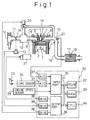
- reference numeral 1 is a direct injection type compression ignition engine proper
- 2 is a piston, 3 a combustion chamber, 4 a fuel injector for directly injecting fuel toward the combustion chamber 3, 5 an intake valve, 6 an intake port, 7 an exhaust valve, and 8 an exhaust port.
- the intake port 6 is connected to a surge tank 10 through a corresponding intake branch 9, while the surge tank 10 is connected to an air cleaner 12 through an intake duct 11.
- a throttle valve 14 controlled to open and close by a drive motor 13.
- the exhaust port 8 is connected to a catalytic converter 18 housing a three-way catalyst 17 through an exhaust manifold 15 and an exhaust pipe 16.
- the exhaust manifold 15 and surge tank 10 are connected to each other by an exhaust gas recirculation (EGR) passage 19.
- EGR exhaust gas recirculation
- the fuel injector 4 is connected to a fuel injection pump 21 driven by the engine. The fuel injected from the fuel injection pump 21 is supplied to the fuel injector 4.
- This fuel injection pump 21 is controlled in discharge based on the output signal of an electronic control unit 30 and therefore the amount of injection from the fuel injector 4 is controlled based on the output signal of the electronic control unit 30.
- the electronic control unit 30 is comprised of a digital computer which is provided with a read only memory (ROM) 32, a random access memory (RAM) 33, a microprocessor (CPU) 34, an input port 35, and an output port 36 connected to each other by a bi-directional bus 31.
- ROM read only memory
- RAM random access memory
- CPU microprocessor
- input port 35 an output port 36 connected to each other by a bi-directional bus 31.
- an air-fuel ratio sensor hereinafter also called an O 2 sensor
- the output signal of the O 2 sensor is input to the input port 35 through a corresponding A/D converter 37.
- an accelerator pedal 23 is connected to a load sensor 24 producing an output voltage proportional to the amount of depression of the accelerator pedal 23.
- the output voltage of the load sensor 24 is input to the input port 35 through a corresponding A/D converter 37. Further, the input port 35 has connected to it an engine speed sensor 35 producing an output pulse showing the engine speed. On the other hand, the output port 36 is connected to the drive motor 13, EGR control valve 20, and fuel injection pump 21 through a corresponding drive circuit 38.
- fuel containing oxygen is used as the fuel injected from the fuel injector 4 to the inside of the combustion chamber 3. Further, the mean air-fuel ratio in the combustion chamber 3 is maintained at substantially the stoichiometric air-fuel ratio.
- the fuel containing oxygen use may be made of either fuel containing oxygen atoms in the molecules themselves or fuel obtained by adding an additive containing oxygen. No matter which type of fuel is used, oxygen ends up being contained in the fuel injected from the fuel injector 4.
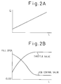
- Figure 2A shows the relationship between the amount Q of injection of fuel containing oxygen and the amount of depression L of the accelerator pedal 23 in the case of a constant engine speed.
- the fuel injection amount Q becomes larger the greater the amount of depression L of the accelerator pedal 23, that is, the greater the engine load.
- the fuel injection amount Q is a function of not only the amount of depression L of the accelerator pedal 23, but also the engine speed N. Accordingly, the fuel injection amount Q is stored in advance in the ROM 32 in the form of the map shown in Fig. 3A.
- the method may be employed of increasing the amount of recirculation of the EGR gas and reducing the amount of intake air supplied into the combustion chamber 3 the lower the engine load or the method may be employed of reducing the degree of opening of the throttle valve 14 and reducing the amount of intake air supplied into the combustion chamber 3 the lower the engine load. Further, these methods may be employed at the same time.
- Figure 2B shows the case of these methods employed simultaneously. In this case, as shown by Fig.
- the degree of opening of the EGR control valve 20 and the degree of opening of the throttle valve 14 are functions of not only the amount of depression L of the accelerator pedal 23, but also the engine speed N. Accordingly, the degree of opening G of the EGR control valve 20 and the degree of opening ⁇ of the throttle valve 14 are stored in advance in the ROM 32 in the form of the maps shown in Fig. 3B and 3C.
- the mean air-fuel ratio in the combustion chamber 3 becomes substantially the stoichiometric air-fuel ratio.
- oxygen is not included in the fuel, the fuel injected from the fuel injector 4 becomes extremely rich in the vaporized area and therefore a large amount of soot is produced.
- the oxygen is included in the fuel, so the oxygen is uniformly dispersed in the vaporized fuel and therefore the fuel particles are burned in the presence of sufficient oxygen and excellent combustion not accompanied by the production of soot can be obtained.
- the degree of opening G of the EGR control valve 20 shown in Fig. 3A and the degree of opening ⁇ of the throttle valve 14 shown in Fig. 3C of course are set so that the air-fuel ratio in the combustion chamber 3 becomes the stoichiometric air-fuel ratio after considering the amount of oxygen included in the fuel.
- the air-fuel ratio in the combustion chamber 3 can be maintained at substantially the stoichiometric air-fuel ratio, so it is possible to obtain a high engine output power.
- the fuel injection amount Q or the amount of EGR gas is feedback controlled based on the output signal of the O 2 sensor 22 so that the mean air-fuel ratio in the combustion chamber 3 becomes the stoichiometric air-fuel ratio. Note that performing feedback control in this way also enables the purification action of the three-way catalyst 17 on NOx, HC, and CO to be enhanced.
- the O 2 sensor 22 products an output voltage V of about 0.1V as shown in Fig. 4 when the mean air-fuel ratio in the combustion chamber 3 is lean and produces an output voltage V of about 0.9V when the mean air-fuel ratio in the combustion chamber 3 is rich.
- the fuel injection amount Q is corrected by the feedback correction coefficient FAF.
- This feedback correction coefficient FAF is controlled based on the output voltage V of the O 2 sensor 22 as shown in Fig. 4.
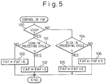
- Figure 5 shows the routine for controlling the feedback correction coefficient FAF based on the output voltage V of the O 2 sensor 22. This routine is performed by interruption every predetermined time interval.
- step 100 it is determined if the output voltage V of the O 2 sensor 22 is higher than a reference value Vr (Fig. 4).
- V > Vr that is, when the ratio is rich
- the routine proceeds to step 101, where it is determined if the ratio was lean at the time of the previous interruption.
- step 102 where a skip value S is subtracted from the feedback correction coefficient FAF.
- step 104 the integration value K (K ⁇ S) is subtracted from FAF. Accordingly, as shown in Fig. 4, when the ratio changes from lean to rich, the FAF is rapidly decreased by the skip amount S and then gradually decreased.
- step 104 it is determined if the ratio was rich at the time of the previous interruption.
- step 105 the skip valve S is added to FAF.
- step 106 the integration value K is added to FAF. Accordingly, as shown in Fig. 4, when the ratio changes from rich to lean, the FAF is rapidly increased by the skip amount S and then gradually increased.
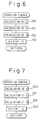
- Figure 6 shows the routine for controlling the operation of the engine. This routine is repeatedly executed.
- the fuel injection amount Q is calculated from the map shown in Fig. 3A.
- the degree of opening G of the EGR control valve 20 is calculated from the map shown in Fig. 3B and the degree of opening of the EGR control valve 20 is controlled to this degree of opening G.
- the degree of opening ⁇ of the throttle valve 14 is calculated from the map shown in Fig. 3C and the drive motor 13 is driven so that the throttle valve 14 becomes this degree of opening ⁇ .
- the feedback correction coefficient FAF is multiplied with the fuel injection amount Q so as to find the final fuel injection amount Q and the fuel injection pump 21 is controlled to be able to inject this amount Q.
- Figure 7 shows the routine for controlling the operation of the engine in the case of controlling the amount of EGR gas so that the mean air-fuel ratio in the combustion chamber 3 becomes the stoichiometric air-fuel ratio. Note that in this case as well, the routine shown in Fig. 5 is used for calculating the feedback correction coefficient FAF.
- the fuel injection amount Q is calculated from the map shown in Fig. 3A and the fuel injection pump 21 is controlled so as to be able to inject this amount Q.
- the degree of opening G of the EGR control valve 20 is calculated from the map shown in Fig. 3B.
- the degree of opening ⁇ of the throttle valve 13 is calculated from the map shown in Fig. 3C and the drive motor 13 is driven so that the throttle valve 14 becomes this degree of opening ⁇ .
- the feedback correction coefficient FAF is multiplied with the degree of opening G of the EGR control valve 20 so as to find the final degree of opening G of the EGR control valve 20.
- the degree of opening of the EGR control valve 20 is controlled to this degree of opening G.
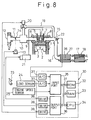
- Figure 8 to Fig. 18 show another embodiment.
- a fuel containing oxygen in the above way, it is possible to obtain excellent combustion not accompanied by the production of soot even if maintaining the air-fuel ratio at the stoichiometric air-fuel ratio.
- problems occur if maintaining the air-fuel ratio at the stoichiometric air-fuel ratio when the engine is operating under a light load or a heavy load.
- the casing 27 housing the NOx absorbent 26 is arranged in the engine exhaust passage upstream of the catalytic converter 18 housing the three-way catalyst 17.
- Figure 9 shows the relationship among the amount of depression L of the accelerator pedal 23, the engine speed N, and the target excess air rate ⁇ , that is, the target air-fuel ratio (A/F) 0 .
- the target excess air rate ⁇ is made 1.0, that is, the target air-fuel ratio (A/F) 0 is made the stoichiometric air-fuel ratio.
- the target excess air rate ⁇ is made larger than 1.0, that is, the target air-fuel ratio (A/F) 0 is made lean.
- the method may be employed of increasing the amount of recirculation of the EGR gas and reducing the amount of intake air supplied into the combustion chamber 3 the lower the engine load or the method may be employed of reducing the degree of opening of the throttle valve 14 and reducing the amount of intake air supplied into the combustion chamber 3 the lower the engine load. Further, these methods may be employed at the same time.
- the solid line in Fig. 10 shows the case of these methods employed simultaneously. In this case, as shown by the solid line in Fig.
- the degree of opening of the EGR control valve 20 and the degree of opening of the throttle valve 14 are functions of not only the amount of depression L of the accelerator pedal 23, but also the engine speed N. Accordingly, the degree of opening G of the EGR control valve 20 and the degree of opening ⁇ of the throttle valve 14 are stored in advance in the ROM 32 in the form of the maps shown in Fig. 11A and 11B.
- the mean air-fuel ratio in the combustion chamber 3 becomes the target air-fuel ratio (A/F) 0 .
- the degree of opening G of the EGR control valve 20 shown in Fig. 11A and the degree of opening ⁇ of the throttle valve 14 shown in Fig. 11B are set so that the air-fuel ratio in the combustion chamber 3 becomes the target air-fuel ratio (A/F) 0 after considering the amount of oxygen included in the fuel.
- the fuel injection amount Q is feedback controlled based on the output signal of the air-fuel ratio sensor 22 so that the mean air-fuel ratio in the combustion chamber 3 becomes the target air-fuel ratio (A/F) 0 .
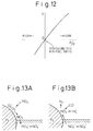
- the air-fuel ratio sensor 22 shown in Fig. 8 has properties different from the O 2 sensor 22 shown in Fig. 1.
- Figure 12 shows the relationship between the output voltage V of the air-fuel ratio sensor 22 shown in Fig. 8 and the mean air-fuel ratio A/F in the combustion chamber 3. From Fig. 12, it is learned that if the air-fuel ratio sensor 22 shown in Fig. 8 is used, it is possible to detect the mean air-fuel ratio A/F in the combustion chamber 3.
- the air-fuel ratio sensor 22 shown in Fig. 8 is used, it is possible to detect the mean air-fuel ratio A/F in the combustion chamber 3.
- the mean air-fuel ratio A/F is feedback controlled to the stoichiometric air-fuel ratio. At this time, the unburned HC, CO, and NOx contained in the exhaust gas are removed well by the three-way catalyst 17.
- the mean air-fuel ratio A/F is feedback controlled to the target air-fuel ratio (A/F) 0 . If the mean air-fuel ratio A/F is maintained lean, a large amount of NOx is produced, but this NOx is absorbed by the NOx absorbent 26. Next, therefore, this NOx absorbent 26 will be explained.
- the NOx absorbent 16 contained in the casing 27 is for example comprised of a carrier of alumina on which are carried for example a precious metal such as platinum Pt and at least one element selected from the group of alkali metals such as potassium K, sodium Na, lithium Li, and cesium Cs, alkali earths such as barium Ba and calcium Ca, and rare earths such as lanthanum La and yttrium Y.
- a precious metal such as platinum Pt and at least one element selected from the group of alkali metals such as potassium K, sodium Na, lithium Li, and cesium Cs, alkali earths such as barium Ba and calcium Ca, and rare earths such as lanthanum La and yttrium Y.
- the NOx absorbent 26 absorbs the NOx when the air-fuel ratio of the inflowing exhaust gas is lean and releases the absorbed NOx when the concentration of oxygen in the inflowing exhaust gas falls, that is, performs an NOx absorbing and releasing action.
- the air-fuel ratio of the inflowing exhaust gas matches with the mean air-fuel ratio in the combustion chamber 3 and therefore in this case the NOx absorbent 26 absorbs the NOx when the mean air-fuel ratio in the combustion chamber 3 is lean and releases the absorbed NOx when the concentration of oxygen in the combustion chamber 3 falls.
- the NOx absorbent 26 does in actuality act to absorb and release NOx, but there are parts of the detailed mechanism of this absorbing and releasing action which are not clear.
- This absorbing and releasing action is thought to be due to the mechanism as shown in Figs. 13A and 13B.
- This mechanism will be explained next taking as an example the case of carrying platinum Pt and barium Ba on the carrier, but the same mechanism works when using other precious metals, alkali metals, alkali earths, and rare earths.
- the concentration of oxygen in the inflowing exhaust gas is high. Therefore, at this time, as shown in Fig. 13A, the oxygen O 2 is deposited on the surface of the platinum Pt in the form of O 2 - or O 2- .
- the NO in the inflowing exhaust gas reacts with the O 2 - or O 2- on the surface of the platinum Pt to become NO 2 (2NO + O 2 ⁇ 2NO 2 ).
- part of the produced NO 2 is oxidized on the platinum Pt and absorbed in the absorbent where it is bonded with the barium oxide BaO and dispersed in the absorbent in the form of nitrate ions NO 3 - as shown in Fig. 13A. In this way, the NOx is absorbed in the NOx absorbent 26.
- NO 2 is produced on the surface of the platinum Pt so long as the concentration of oxygen in the inflowing exhaust gas is high. NO 2 is absorbed in the absorbent and nitrate ions NO 3 - are produced so long as the absorbent does not reach the end of its ability to absorb NOx. As opposed to this, when the concentration of oxygen in the inflowing exhaust gas falls and the amount of NO 2 produced drops, the reaction proceeds in the reverse direction (NO 3 - ⁇ NO 2 ) and therefore nitrate ions NO 3 - in the absorbent are released from the absorbent in the form of NO 2 . That is, when the concentration of oxygen in the inflowing exhaust gas falls, NOx is released from the NOx absorbent 26.
- the NOx absorbent 26 has the function of a reduction catalyst, the NOx released from the NOx absorbent 26 can be reduced even if the air-fuel ratio of the inflowing exhaust gas is made the stoichiometric air-fuel ratio.
- the NOx is released only gradually from the NOx absorbent 26, so it takes a somewhat long time to release all of the NOx absorbed in the NOx absorbent 26.
- the NOx absorbent 26 As explained above, when the mean air-fuel ratio A/F in the combustion chamber 3 is maintained lean, the NOx continues to be absorbed in the NOx absorbent 26. However, there is a limit to the ability of the NOx absorbent 26 to absorb NOx. When the NOx absorbent 26 reaches its limit in capacity to absorb NOx, the NOx absorbent 26 can no longer absorb NOx. Accordingly, it is necessary to release the NOx from the NOx absorbent 26 before the NOx absorbent 26 reaches the limit of its capacity to absorb NOx. Therefore, it is necessary to estimate what degree of NOx has been absorbed in the NOx absorbent 26. The method of estimating the amount of absorption of NOx will be explained briefly next.
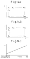
- the amount of NOx absorbed in the NOx absorbent 26 per unit time becomes a function of the engine load and the engine speed. Accordingly, in the embodiment shown in Fig. 8, the amount A of NOx absorbed in the NOx absorbent 26 per unit time is found in advance by experiments as a function of the amount of depression L of the accelerator pedal 23 and the engine speed N. The NOx amount A is stored in the advance in the ROM 32 in the form of the map shown in Fig. 14A as a function of L and N.
- the NOx release D released from the NOx absorbent 26 per unit time is proportional to the amount of exhaust gas and proportional to the degree of richness of the mean air-fuel ratio A/F.
- the amount of exhaust gas is a function of the amount of depression L of the accelerator pedal 23 and the engine speed N, so the NOx release D also becomes a function of the amount of depression L of the accelerator pedal 23 and the engine speed N.
- the NOx release D is stored in advance in the ROM 32 in the form of the map shown in Fig. 14B.
- Figure 15 shows the changes in the estimated absorbed NOx ⁇ NOx.
- the mean air-fuel ratio A/F when the mean air-fuel ratio A/F is lean, the estimated absorbed NOx ⁇ NOx gradually increases.
- the mean air-fuel ratio A/F is maintained at the stoichiometric air-fuel ratio, the estimated absorbed NOx ⁇ NOx is gradually reduced.
- the mean air-fuel ratio A/F exceeds a previously determined upper limit MAX, the mean air-fuel ratio A/F is made rich for a short period in a spike fashion, where the NOx is made to be discharged from the NOx absorbent 26.
- the mean air-fuel ratio A/F in the combustion chamber 3 is made rich.
- oxygen is included in the fuel, so the oxygen is uniformly dispersed in the vaporized fuel and accordingly the fuel particles are made to burn in the presence of a large amount of oxygen, so only a small amount of soot is produced. That is, by using fuel containing oxygen in this way, it becomes possible for the first time to make the mean air-fuel ratio in the combustion chamber 3 rich.
- the degree of opening of the EGR control valve 20 is made larger and the degree of opening of the throttle valve 14 is made smaller and, further, the amount of fuel injection is increased so as to make the mean air-fuel ratio A/F rich.
- Figure 16 shows the changes in the mean air-fuel ratio A/F etc. at this time. Note that the broken line in Fig. 10 shows the degree of opening G' of the EGR control valve 20 and the degree of opening ⁇ ' of the throttle valve 14 at this time.
- Figure 17 and Fig. 18 show the routine for controlling the operation of the engine.
- the routine is executed for example by interruption at predetermined time intervals.
- step 250 the fuel injection amount Q is calculated from the map shown in Fig. 3A.
- step 251 it is determined if the NOx releasing flag set when the NOx is to be released from the NOx absorbent 26 is set or not.
- the routine proceeds to step 252, where the degree of opening G of the EGR control valve 20 is calculated from the map shown in Fig. 11A, then at step 253, the degree of opening ⁇ of the throttle valve 14 is calculated from the map shown in Fig. 11B.
- step 254 it is determined if the mean air-fuel ratio A/F in the combustion chamber 3 detected by the air-fuel ratio sensor 22 is larger than the target air-fuel ratio (A/F) 0 .
- the routine proceeds to step 255, where a predetermined value K is added to the feedback correction coefficient FAF, then the routine proceeds to step 257.
- the routine proceeds to step 256, where the predetermined value K is subtracted from the feedback correction coefficient FAF, then the routine proceeds to step 257.
- step 258 it is determined if the target air-fuel ratio (A/F) 0 is the stoichiometric air-fuel ratio.
- the routine proceeds to step 259, where the NOx absorption A shown in the map of Fig. 14A is added to the estimated absorbed NOx ⁇ NOx, then the routine proceeds to step 263.
- step 260 the product K ⁇ D of the NOx release D found from Fig. 14B and the NOx release rate K found from Fig. 14C based on the mean air-fuel ratio ( 14.7 ⁇ Q/(Q+ ⁇ Q) ) is subtracted from the estimated absorbed NOx ⁇ NOx.
- step 261 it is determined if the estimated absorbed NOx ⁇ NOx has become negative or not.
- the routine proceeds to step 262, where the estimated absorbed NOx ⁇ NOx is made zero, then the routine proceeds to step 263.
- step 263 it is determined if the estimated absorbed NOx ⁇ NOx has exceeded the upper limit MAX.
- ⁇ NOx ⁇ MAX the processing cycle ends.
- the routine proceeds to step 264, where the NOx releasing flag is set.
- the routine proceeds from step 251 to step 265 where the release of NOx from the NOx absorbent 26 is controlled.
- step 265 the degree of opening G' of the EGR control valve 20 shown in Fig. 10 was calculated and the EGR control valve 20 was opened to this degree of opening G'.
- step 266 the degree of opening ⁇ ' of the throttle valve 14 shown in Fig. 10 was calculated and the throttle valve 14 was closed to this degree of opening ⁇ '.
- step 267 it is decided if a predetermined time has elapsed from the start of the operation for opening the EGR control valve 20 and the operation for closing the throttle valve 14. When a predetermined time has elapsed, the routine proceeds to step 268.
- the fuel injection amount Q is increased by exactly ⁇ Q whereby the mean air-fuel ratio A/F is made rich.
- the product K ⁇ D of the NOx release D found from Fig. 14B and the NOx release rate K found from Fig. 14C based on the mean air-fuel ratio ( 14.7 ⁇ Q/(Q+ ⁇ Q) ) is subtracted from the estimated absorbed NOx ⁇ NOx.
- step 271 the estimated absorbed NOx ⁇ NOx is made zero, then the routine proceeds to step 272, where the NOx releasing flag is reset.
- the NOx releasing flag is reset, at the next processing cycle, the EGR control valve 20 is closed to the degree of opening G and the throttle valve 14 is opened to the degree of opening ⁇ .
- the NOx absorbent 26 is arranged upstream of the three-way catalyst 17. If the NOx absorbent 26 is arranged upstream of the three-way catalyst 17 in this way, there is the advantage that the NOx which could not be reduced in the NOx absorbent 26 at the time of release of the NOx from the NOx absorbent 26 can be reduced by the three-way catalyst 17.
Abstract
Description
- The present invention relates to a direct injection type compression ignition engine.
- To obtain a high output power in an internal combustion engine, it is desirable to make the mean air-fuel ratio in the combustion chamber the stoichiometric air-fuel ratio. The same is true for a diesel engine. In a diesel engine which directly injects fuel into the combustion chamber, however, when the mean air-fuel ratio in the combustion chamber is made the stoichiometric air-fuel ratio, the atomized fuel becomes extremely rich and a large amount of soot is produced. Accordingly, in the past, it was not possible to make the air-fuel ratio in the combustion chamber of a diesel engine the stoichiometric air-fuel ratio and so the combustion chamber was given an excess of air (for example, see Japanese Unexamined Utility Model Publication (Kokai) No. 62-56743).
- When injecting fuel into an intake passage, the injected fuel is uniformly dispersed in the combustion chamber, so even if the mean air-fuel ratio in the combustion chamber is made the stoichiometric air-fuel ratio, no soot is produced, but in this case explosive combustion occurs. According, this technique could not be adopted.
- Therefore, in the past, there was the problem in diesel engines that the combustion chamber had to be given an excess of air and accordingly the engine output power could not be improved.
- An object of the present invention is to provide a direct injection type compression ignition engine in which the output power can be improved.
- According to the present invention, there is provided a compression ignition engine having a combustion chamber comprising fuel injection means for injecting fuel containing oxygen into the combustion chamber and means for determining an amount of fuel injected from the fuel injection means so that a mean value of an air-fuel ratio in the combustion chamber becomes equal to a target air-fuel ratio selected from one of the stoichiometric air-fuel ratio and a lean air-fuel ratio.
- The present invention may be more fully understood from the description of the preferred embodiments of the invention set forth below, together with the accompanying drawings, in which:
- Fig. 1 is an overall view of an internal combustion engine;
- Figs. 2A and 2B are views showing the amount of fuel injection, degree of opening of an EGR control valve, and degree of opening of a throttle valve;
- Figs. 3A, 3B, and 3C show maps of the amount of fuel injection etc.:
- Fig. 4 is a view of the changes in the feedback correction coefficient FAF;
- Fig. 5 is a flow chart of the control by the feedback correction coefficient;
- Fig. 6 is a flow chart of the control of the engine operation;
- Fig. 7 is a flow chart of another embodiment for control of the engine operation;
- Fig. 8 is an overall view of another embodiment of the internal combustion engine;
- Fig. 9 is a view of the excess air rate γ, that is, the target air-fuel ratio (A/F)0;
- Fig. 10 is a graph of the degrees of opening of the EGR control valve and throttle valve;
- Figs. 11A and 11B show maps of the degree of opening G of the EGR valve and the degree of opening θ of the throttle valve;
- Fig. 12 is a graph of the output of the air-fuel ratio sensor;
- Figs. 13A and 13B are views for explaining the absorbing and releasing action of an NOx absorbent;
- Figs. 14A, 14B, and 14C show maps of the amount A of NOx absorption etc.;
- Fig. 15 is a time chart of the changes in the estimated absorbed NOx ΣNOx;
- Fig. 16 is a time chart of the control of release of NOx; and
- Figs. 17 and 18 are flow charts for the control of the operation.
- Referring to Fig. 1,
reference numeral 1 is a direct injection type compression ignition engine proper, 2 is a piston, 3 a combustion chamber, 4 a fuel injector for directly injecting fuel toward thecombustion chamber intake port 6 is connected to asurge tank 10 through acorresponding intake branch 9, while thesurge tank 10 is connected to anair cleaner 12 through anintake duct 11. In theintake duct 11 is disposed athrottle valve 14 controlled to open and close by adrive motor 13. On the other hand, theexhaust port 8 is connected to acatalytic converter 18 housing a three-way catalyst 17 through anexhaust manifold 15 and anexhaust pipe 16. - The
exhaust manifold 15 andsurge tank 10 are connected to each other by an exhaust gas recirculation (EGR)passage 19. In thisEGR passage 19 is disposed anEGR control valve 20 for controlling the amount of EGR gas recirculated in thesurge tank 10 from theexhaust manifold 15. On the other hand, thefuel injector 4 is connected to afuel injection pump 21 driven by the engine. The fuel injected from thefuel injection pump 21 is supplied to thefuel injector 4. Thisfuel injection pump 21 is controlled in discharge based on the output signal of anelectronic control unit 30 and therefore the amount of injection from thefuel injector 4 is controlled based on the output signal of theelectronic control unit 30. - The
electronic control unit 30 is comprised of a digital computer which is provided with a read only memory (ROM) 32, a random access memory (RAM) 33, a microprocessor (CPU) 34, aninput port 35, and anoutput port 36 connected to each other by abi-directional bus 31. In theexhaust manifold 15 is disposed an air-fuel ratio sensor (hereinafter also called an O2 sensor) for detecting the mean air-fuel ratio in thecombustion chamber 3 from the concentration of oxygen in the exhaust gas. The output signal of the O2 sensor is input to theinput port 35 through a corresponding A/D converter 37. Further, anaccelerator pedal 23 is connected to aload sensor 24 producing an output voltage proportional to the amount of depression of theaccelerator pedal 23. The output voltage of theload sensor 24 is input to theinput port 35 through a corresponding A/D converter 37. Further, theinput port 35 has connected to it anengine speed sensor 35 producing an output pulse showing the engine speed. On the other hand, theoutput port 36 is connected to thedrive motor 13,EGR control valve 20, andfuel injection pump 21 through acorresponding drive circuit 38. - In the embodiment shown in Fig. 1, fuel containing oxygen is used as the fuel injected from the
fuel injector 4 to the inside of thecombustion chamber 3. Further, the mean air-fuel ratio in thecombustion chamber 3 is maintained at substantially the stoichiometric air-fuel ratio. In this case, as the fuel containing oxygen, use may be made of either fuel containing oxygen atoms in the molecules themselves or fuel obtained by adding an additive containing oxygen. No matter which type of fuel is used, oxygen ends up being contained in the fuel injected from thefuel injector 4. - Figure 2A shows the relationship between the amount Q of injection of fuel containing oxygen and the amount of depression L of the
accelerator pedal 23 in the case of a constant engine speed. As shown in Fig. 2A, the fuel injection amount Q becomes larger the greater the amount of depression L of theaccelerator pedal 23, that is, the greater the engine load. Note that in practice the fuel injection amount Q is a function of not only the amount of depression L of theaccelerator pedal 23, but also the engine speed N. Accordingly, the fuel injection amount Q is stored in advance in theROM 32 in the form of the map shown in Fig. 3A. - On the other hand, to maintain the mean air-fuel ratio in the
combustion chamber 3 at substantially the stoichiometric air-fuel ratio, the method may be employed of increasing the amount of recirculation of the EGR gas and reducing the amount of intake air supplied into thecombustion chamber 3 the lower the engine load or the method may be employed of reducing the degree of opening of thethrottle valve 14 and reducing the amount of intake air supplied into thecombustion chamber 3 the lower the engine load. Further, these methods may be employed at the same time. Figure 2B shows the case of these methods employed simultaneously. In this case, as shown by Fig. 2B, the smaller the amount of depression L of theaccelerator pedal 23, the greater the degree of opening theEGR control valve 20 is made, that is, the more the amount of EGR gas is increased and at the same time the smaller the degree of opening thethrottle valve 14 is made. Note that in practice the degree of opening of theEGR control valve 20 and the degree of opening of thethrottle valve 14 are functions of not only the amount of depression L of theaccelerator pedal 23, but also the engine speed N. Accordingly, the degree of opening G of theEGR control valve 20 and the degree of opening θ of thethrottle valve 14 are stored in advance in theROM 32 in the form of the maps shown in Fig. 3B and 3C. - Accordingly, based on the amount of depression L of the
accelerator pedal 23 and the engine speed N, when the value shown in Fig. 3A is made the fuel injection amount Q, the value shown in Fig. 3B is made the degree of opening G of theEGR control valve 20, and the value shown in Fig. 3C is made the degree of opening θ of thethrottle valve 14, the mean air-fuel ratio in thecombustion chamber 3 becomes substantially the stoichiometric air-fuel ratio. In this case, if oxygen is not included in the fuel, the fuel injected from thefuel injector 4 becomes extremely rich in the vaporized area and therefore a large amount of soot is produced. In the present invention, however, oxygen is included in the fuel, so the oxygen is uniformly dispersed in the vaporized fuel and therefore the fuel particles are burned in the presence of sufficient oxygen and excellent combustion not accompanied by the production of soot can be obtained. Note that the degree of opening G of theEGR control valve 20 shown in Fig. 3A and the degree of opening θ of thethrottle valve 14 shown in Fig. 3C of course are set so that the air-fuel ratio in thecombustion chamber 3 becomes the stoichiometric air-fuel ratio after considering the amount of oxygen included in the fuel. - In this way, in the embodiment shown in Fig. 1, the air-fuel ratio in the
combustion chamber 3 can be maintained at substantially the stoichiometric air-fuel ratio, so it is possible to obtain a high engine output power. - However, when the content of the oxygen in the fuel is different from the pretargeted content, if Q, G, and θ are determined from the maps shown in Figs. 3A, 3B, and 3C, the mean air-fuel ratio in the
combustion chamber 3 will end up deviated from the target air-fuel ratio (A/F)0. Therefore, in the embodiment shown in Fig. 1, the fuel injection amount Q or the amount of EGR gas is feedback controlled based on the output signal of the O2 sensor 22 so that the mean air-fuel ratio in thecombustion chamber 3 becomes the stoichiometric air-fuel ratio. Note that performing feedback control in this way also enables the purification action of the three-way catalyst 17 on NOx, HC, and CO to be enhanced. - Next, the feedback control will be explained. The O2 sensor 22 products an output voltage V of about 0.1V as shown in Fig. 4 when the mean air-fuel ratio in the
combustion chamber 3 is lean and produces an output voltage V of about 0.9V when the mean air-fuel ratio in thecombustion chamber 3 is rich. When performing feedback control on the fuel injection amount Q, the fuel injection amount Q is corrected by the feedback correction coefficient FAF. This feedback correction coefficient FAF is controlled based on the output voltage V of the O2 sensor 22 as shown in Fig. 4. - Figure 5 shows the routine for controlling the feedback correction coefficient FAF based on the output voltage V of the O2 sensor 22. This routine is performed by interruption every predetermined time interval.
- Referring to Fig. 5, first, at
step 100, it is determined if the output voltage V of the O2 sensor 22 is higher than a reference value Vr (Fig. 4). When V > Vr, that is, when the ratio is rich, the routine proceeds to step 101, where it is determined if the ratio was lean at the time of the previous interruption. When it was lean at the time of the previous interruption, the routine proceeds to step 102, where a skip value S is subtracted from the feedback correction coefficient FAF. As opposed to this, when the ratio was rich at the time of the previous interruption, the routine proceeds to step 104, where the integration value K (K <<S) is subtracted from FAF. Accordingly, as shown in Fig. 4, when the ratio changes from lean to rich, the FAF is rapidly decreased by the skip amount S and then gradually decreased. - On the other hand, when it is determined at
step 100 that V ≦ Vr, that is, when it is determined that the ratio is lean, the routine proceeds to step 104 where it is determined if the ratio was rich at the time of the previous interruption. When it was rich at the time of the previous interruption, the routine proceeds to step 105, where the skip valve S is added to FAF. As opposed to this, when it was lean at the time of the previous interruption, the routine proceeds to step 106, where the integration value K is added to FAF. Accordingly, as shown in Fig. 4, when the ratio changes from rich to lean, the FAF is rapidly increased by the skip amount S and then gradually increased. - Figure 6 shows the routine for controlling the operation of the engine. This routine is repeatedly executed.
- Referring to Fig. 6, first, at
step 150, the fuel injection amount Q is calculated from the map shown in Fig. 3A. Next, atstep 151, the degree of opening G of theEGR control valve 20 is calculated from the map shown in Fig. 3B and the degree of opening of theEGR control valve 20 is controlled to this degree of opening G. Next, atstep 152, the degree of opening θ of thethrottle valve 14 is calculated from the map shown in Fig. 3C and thedrive motor 13 is driven so that thethrottle valve 14 becomes this degree of opening θ. Next, atstep 153, the feedback correction coefficient FAF is multiplied with the fuel injection amount Q so as to find the final fuel injection amount Q and thefuel injection pump 21 is controlled to be able to inject this amount Q. - Figure 7 shows the routine for controlling the operation of the engine in the case of controlling the amount of EGR gas so that the mean air-fuel ratio in the
combustion chamber 3 becomes the stoichiometric air-fuel ratio. Note that in this case as well, the routine shown in Fig. 5 is used for calculating the feedback correction coefficient FAF. - Referring to Fig. 7, first, at
step 200, the fuel injection amount Q is calculated from the map shown in Fig. 3A and thefuel injection pump 21 is controlled so as to be able to inject this amount Q. Next, atstep 201, the degree of opening G of theEGR control valve 20 is calculated from the map shown in Fig. 3B. Next, atstep 202, the degree of opening θ of thethrottle valve 13 is calculated from the map shown in Fig. 3C and thedrive motor 13 is driven so that thethrottle valve 14 becomes this degree of opening θ. Next, atstep 203, the feedback correction coefficient FAF is multiplied with the degree of opening G of theEGR control valve 20 so as to find the final degree of opening G of theEGR control valve 20. The degree of opening of theEGR control valve 20 is controlled to this degree of opening G. - Figure 8 to Fig. 18 show another embodiment. When using a fuel containing oxygen in the above way, it is possible to obtain excellent combustion not accompanied by the production of soot even if maintaining the air-fuel ratio at the stoichiometric air-fuel ratio. However, with some types of direct injection compression ignition engines, problems occur if maintaining the air-fuel ratio at the stoichiometric air-fuel ratio when the engine is operating under a light load or a heavy load. That is, when the engine is operating under a light load, a large amount of EGR gas is recirculated, so the amount of air in the
combustion chamber 3 becomes small and therefore if the air-fuel ratio is maintained at the stoichiometric air-fuel ratio at this time, there is insufficient air, even if a fuel containing oxygen is used, and so the combustion becomes unstable. - Further, when the engine is operating under a high load with a large amount of fuel injection, the uneven dispersion of the injected fuel causes an overly rich air-fuel mixture region to be formed in the
combustion chamber 3 and therefore at this time if the air-fuel ratio is made the stoichiometric air-fuel ratio, even if fuel containing oxygen is used, there will be insufficient air and therefore soot will be produced. Accordingly, it is necessary to make the air-fuel ratio lean when the engine is operating under a light load and operating under a heavy load in a compression ignition engine of this type. Figure 8 to Fig. 18 show an embodiment suited to this type of compression ignition engine. - First, referring to Fig. 8, in this embodiment, the
casing 27 housing theNOx absorbent 26 is arranged in the engine exhaust passage upstream of thecatalytic converter 18 housing the three-way catalyst 17. - Figure 9 shows the relationship among the amount of depression L of the
accelerator pedal 23, the engine speed N, and the target excess air rate λ, that is, the target air-fuel ratio (A/F)0. As shown in Fig. 9, when the engine is operating at a medium speed under a medium load, the target excess air rate λ is made 1.0, that is, the target air-fuel ratio (A/F)0 is made the stoichiometric air-fuel ratio. In other areas, the target excess air rate λ is made larger than 1.0, that is, the target air-fuel ratio (A/F)0 is made lean. - On the other hand, to maintain the excess air rate λ at the target excess air rate shown in Fig. 9, that is, to maintain the mean air-fuel ratio in the
combustion chamber 3 at the target air-fuel ratio (A/F)0, the method may be employed of increasing the amount of recirculation of the EGR gas and reducing the amount of intake air supplied into thecombustion chamber 3 the lower the engine load or the method may be employed of reducing the degree of opening of thethrottle valve 14 and reducing the amount of intake air supplied into thecombustion chamber 3 the lower the engine load. Further, these methods may be employed at the same time. The solid line in Fig. 10 shows the case of these methods employed simultaneously. In this case, as shown by the solid line in Fig. 10, the smaller the amount of depression L of theaccelerator pedal 23, the greater the degree of opening theEGR control valve 20 is made, that is, the more the amount of EGR gas is increased and at the same time the smaller the degree of opening thethrottle valve 14 is made. Note that in practice the degree of opening of theEGR control valve 20 and the degree of opening of thethrottle valve 14 are functions of not only the amount of depression L of theaccelerator pedal 23, but also the engine speed N. Accordingly, the degree of opening G of theEGR control valve 20 and the degree of opening θ of thethrottle valve 14 are stored in advance in theROM 32 in the form of the maps shown in Fig. 11A and 11B. - Accordingly, based on the amount of depression L of the
accelerator pedal 23 and the engine speed N, when the value shown in Fig. 3A is made the fuel injection amount Q, the value shown in Fig. 11A is made the degree of opening G of theEGR control valve 20, and the value shown in Fig. 11B is made the degree of opening θ of thethrottle valve 14, the mean air-fuel ratio in thecombustion chamber 3 becomes the target air-fuel ratio (A/F)0. Note that the degree of opening G of theEGR control valve 20 shown in Fig. 11A and the degree of opening θ of thethrottle valve 14 shown in Fig. 11B are set so that the air-fuel ratio in thecombustion chamber 3 becomes the target air-fuel ratio (A/F)0 after considering the amount of oxygen included in the fuel. - However, when the content of the oxygen in the fuel is different from the pretargeted content, if Q, G, and θ are determined from the maps shown in Fig. 3A and Figs. 11A and 11B, the mean air-fuel ratio in the
combustion chamber 3 will end up deviated from the target air-fuel ratio (A/F)0. Therefore, in this embodiment as well, the fuel injection amount Q is feedback controlled based on the output signal of the air-fuel ratio sensor 22 so that the mean air-fuel ratio in thecombustion chamber 3 becomes the target air-fuel ratio (A/F)0. - Next, the feedback control will be simply explained. The air-
fuel ratio sensor 22 shown in Fig. 8 has properties different from the O2 sensor 22 shown in Fig. 1. Figure 12 shows the relationship between the output voltage V of the air-fuel ratio sensor 22 shown in Fig. 8 and the mean air-fuel ratio A/F in thecombustion chamber 3. From Fig. 12, it is learned that if the air-fuel ratio sensor 22 shown in Fig. 8 is used, it is possible to detect the mean air-fuel ratio A/F in thecombustion chamber 3. In the embodiment shown in Fig. 8, when the mean air-fuel ratio A/F detected by the air-fuel ratio sensor 22 is larger than the target air-fuel ratio (A/F)0, the fuel injection amount Q is increased, while when the mean air-fuel ratio A/F detected by the air-fuel ratio sensor 22 is smaller than the target air-fuel ratio (A/F)0, the fuel injection amount Q is reduced. The mean air-fuel ratio A/F is controlled to the target air-fuel ratio (A/F)0 in this way. - That is, in this embodiment, when the engine is operating at a medium speed under a medium load, the mean air-fuel ratio A/F is feedback controlled to the stoichiometric air-fuel ratio. At this time, the unburned HC, CO, and NOx contained in the exhaust gas are removed well by the three-
way catalyst 17. On the other hand, when the engine is operating other than at medium speed and under a medium load, the mean air-fuel ratio A/F is feedback controlled to the target air-fuel ratio (A/F)0. If the mean air-fuel ratio A/F is maintained lean, a large amount of NOx is produced, but this NOx is absorbed by theNOx absorbent 26. Next, therefore, thisNOx absorbent 26 will be explained. - The NOx absorbent 16 contained in the
casing 27 is for example comprised of a carrier of alumina on which are carried for example a precious metal such as platinum Pt and at least one element selected from the group of alkali metals such as potassium K, sodium Na, lithium Li, and cesium Cs, alkali earths such as barium Ba and calcium Ca, and rare earths such as lanthanum La and yttrium Y. If the ratio of the air and fuel supplied into the engine intake passage,combustion chamber 3, and exhaust passage upstream of theNOx absorbent 26 is defined as the air-fuel ratio of the inflowing exhaust gas flowing into theNOx absorbent 26, theNOx absorbent 26 absorbs the NOx when the air-fuel ratio of the inflowing exhaust gas is lean and releases the absorbed NOx when the concentration of oxygen in the inflowing exhaust gas falls, that is, performs an NOx absorbing and releasing action. Note that when the fuel or air is not supplied in the exhaust passage upstream of theNOx absorbent 26, the air-fuel ratio of the inflowing exhaust gas matches with the mean air-fuel ratio in thecombustion chamber 3 and therefore in this case theNOx absorbent 26 absorbs the NOx when the mean air-fuel ratio in thecombustion chamber 3 is lean and releases the absorbed NOx when the concentration of oxygen in thecombustion chamber 3 falls. - By placing the
above NOx absorbent 26 in the engine exhaust passage, theNOx absorbent 26 does in actuality act to absorb and release NOx, but there are parts of the detailed mechanism of this absorbing and releasing action which are not clear. This absorbing and releasing action, however, is thought to be due to the mechanism as shown in Figs. 13A and 13B. This mechanism will be explained next taking as an example the case of carrying platinum Pt and barium Ba on the carrier, but the same mechanism works when using other precious metals, alkali metals, alkali earths, and rare earths. - When the mean air-fuel ratio A/F in the
combustion chamber 3 is maintained lean, the concentration of oxygen in the inflowing exhaust gas is high. Therefore, at this time, as shown in Fig. 13A, the oxygen O2 is deposited on the surface of the platinum Pt in the form of O2 - or O2-. On the other hand, the NO in the inflowing exhaust gas reacts with the O2 - or O2- on the surface of the platinum Pt to become NO2
NOx absorbent 26. - NO2 is produced on the surface of the platinum Pt so long as the concentration of oxygen in the inflowing exhaust gas is high. NO2 is absorbed in the absorbent and nitrate ions NO3 - are produced so long as the absorbent does not reach the end of its ability to absorb NOx. As opposed to this, when the concentration of oxygen in the inflowing exhaust gas falls and the amount of NO2 produced drops, the reaction proceeds in the reverse direction

NOx absorbent 26. If the degree of leanness of the inflowing exhaust gas falls, the concentration of oxygen in inflowing exhaust gas falls. Therefore, if the degree of leanness of the inflowing exhaust gas falls, NOx is discharged from theNOx absorbent 26 even if the air-fuel ratio of the inflowing exhaust gas is lean. - On the other hand, when the mean air-fuel ratio in the
combustion chamber 3 is made rich and the air-fuel ratio of the inflowing exhaust gas becomes rich at this time, a large amount of unburned HC and CO are exhausted from the engine. These unburned HC and CO react with the oxygen O2 - or O2- on the platinum Pt to be oxidized. Further, when the air-fuel ratio of the inflowing exhaust gas becomes rich, the concentration of oxygen in the inflowing exhaust gas drops sharply, so NO2 is released from the absorbent. This NO2 is reduced by reaction with the unburned HC and CO as shown in Fig. 13B. When there is no longer any NO2 present on the surface of the platinum Pt, the NO2 is released from the absorbent. Accordingly, when the air-fuel ratio of the inflowing exhaust gas is made rich, the NOx is released from theNOx absorbent 26 in a short time. - That is, when the air-fuel ratio of the inflowing exhaust gas is made rich, first, the unburned HC and CO react immediately with the O2 - or O2- on the platinum Pt to be oxidized, then if there is still unburned HC or CO remaining even after the O2 - or O2- on the platinum Pt is consumed, the NOx released from the absorbent and the NOx exhausted from the engine are reduced. Accordingly, by making the air-fuel ratio of the inflowing exhaust gas rich, the NOx absorbed in the
NOx absorbent 26 is released in a short time and, further, the exhausted NOx is reduced, so it is possible to prevent the release of NOx into the atmosphere. Further, since theNOx absorbent 26 has the function of a reduction catalyst, the NOx released from theNOx absorbent 26 can be reduced even if the air-fuel ratio of the inflowing exhaust gas is made the stoichiometric air-fuel ratio. However, when making the air-fuel ratio of the inflowing exhaust gas the stoichiometric air-fuel ratio, the NOx is released only gradually from theNOx absorbent 26, so it takes a somewhat long time to release all of the NOx absorbed in theNOx absorbent 26. - As explained above, when the mean air-fuel ratio A/F in the
combustion chamber 3 is maintained lean, the NOx continues to be absorbed in theNOx absorbent 26. However, there is a limit to the ability of the NOx absorbent 26 to absorb NOx. When theNOx absorbent 26 reaches its limit in capacity to absorb NOx, theNOx absorbent 26 can no longer absorb NOx. Accordingly, it is necessary to release the NOx from theNOx absorbent 26 before theNOx absorbent 26 reaches the limit of its capacity to absorb NOx. Therefore, it is necessary to estimate what degree of NOx has been absorbed in theNOx absorbent 26. The method of estimating the amount of absorption of NOx will be explained briefly next. - When the mean air-fuel ratio in the
combustion chamber 3 is maintained lean, the higher the engine load becomes, the greater the NOx exhausted from the engine per unit time, so the greater the NOx absorbed in the NOx absorbent 26 per unit time. Further, the higher the engine speed, the greater the NOx exhausted from the engine per unit time, so the greater the NOx absorbed in the NOx absorbent 26 per unit time. Accordingly, the amount of NOx absorbed in the NOx absorbent 26 per unit time becomes a function of the engine load and the engine speed. Accordingly, in the embodiment shown in Fig. 8, the amount A of NOx absorbed in the NOx absorbent 26 per unit time is found in advance by experiments as a function of the amount of depression L of theaccelerator pedal 23 and the engine speed N. The NOx amount A is stored in the advance in theROM 32 in the form of the map shown in Fig. 14A as a function of L and N. - On the other hand, if the mean air-fuel ratio A/F becomes the stoichiometric air-fuel ratio or rich, the NOx is discharged from the
NOx absorbent 26. At this time, the NOx release D released from the NOx absorbent 26 per unit time is proportional to the amount of exhaust gas and proportional to the degree of richness of the mean air-fuel ratio A/F. In this case, the amount of exhaust gas is a function of the amount of depression L of theaccelerator pedal 23 and the engine speed N, so the NOx release D also becomes a function of the amount of depression L of theaccelerator pedal 23 and the engine speed N. The NOx release D is stored in advance in theROM 32 in the form of the map shown in Fig. 14B. On the other hand, when the degree of richness of the mean air-fuel ratio A/F becomes higher, the NOx release rate K becomes higher as shown in Fig. 14C and therefore when considering the NOx release rate K, the NOx release per unit time is expressed by K·D. - Since the NOx absorption per unit time is expressed by A and the NOx release per unit time is expressed by K·D in this way, the NOx estimated to be absorbed in the
NOx absorbent 26, that is, ΣNOx, is expressed by the following equation:
- Figure 15 shows the changes in the estimated absorbed NOx ΣNOx. As shown in Fig. 15, when the mean air-fuel ratio A/F is lean, the estimated absorbed NOx ΣNOx gradually increases. When the mean air-fuel ratio A/F is maintained at the stoichiometric air-fuel ratio, the estimated absorbed NOx ΣNOx is gradually reduced. Further, when the estimated absorbed NOx ΣNOx exceeds a previously determined upper limit MAX, the mean air-fuel ratio A/F is made rich for a short period in a spike fashion, where the NOx is made to be discharged from the
NOx absorbent 26. - In the embodiment shown in Fig. 8, in this way, when the NOx is to be discharged from the
NOx absorbent 26, the mean air-fuel ratio A/F in thecombustion chamber 3 is made rich. However, in the present invention, oxygen is included in the fuel, so the oxygen is uniformly dispersed in the vaporized fuel and accordingly the fuel particles are made to burn in the presence of a large amount of oxygen, so only a small amount of soot is produced. That is, by using fuel containing oxygen in this way, it becomes possible for the first time to make the mean air-fuel ratio in thecombustion chamber 3 rich. - However, if the controlling just the amount of fuel injection to make the mean air-fuel ratio in the
combustion chamber 3 rich, that is, making the mean air-fuel ratio rich just by increasing the amount of fuel injection, the output torque rapidly increases and a shock is produced. Therefore, in the embodiment shown in Fig. 8, the degree of opening of theEGR control valve 20 is made larger and the degree of opening of thethrottle valve 14 is made smaller and, further, the amount of fuel injection is increased so as to make the mean air-fuel ratio A/F rich. Figure 16 shows the changes in the mean air-fuel ratio A/F etc. at this time. Note that the broken line in Fig. 10 shows the degree of opening G' of theEGR control valve 20 and the degree of opening θ' of thethrottle valve 14 at this time. - Figure 17 and Fig. 18 show the routine for controlling the operation of the engine. The routine is executed for example by interruption at predetermined time intervals.
- Referring to Fig. 17 and Fig. 18, first, at
step 250, the fuel injection amount Q is calculated from the map shown in Fig. 3A. Next, atstep 251, it is determined if the NOx releasing flag set when the NOx is to be released from theNOx absorbent 26 is set or not. When the NOx releasing flag is not set, the routine proceeds to step 252, where the degree of opening G of theEGR control valve 20 is calculated from the map shown in Fig. 11A, then atstep 253, the degree of opening θ of thethrottle valve 14 is calculated from the map shown in Fig. 11B. - Next, at
step 254, it is determined if the mean air-fuel ratio A/F in thecombustion chamber 3 detected by the air-fuel ratio sensor 22 is larger than the target air-fuel ratio (A/F)0. When A/F > (A/F)0, the routine proceeds to step 255, where a predetermined value K is added to the feedback correction coefficient FAF, then the routine proceeds to step 257. As opposed to this, when A/F ≦ (A/F)0, the routine proceeds to step 256, where the predetermined value K is subtracted from the feedback correction coefficient FAF, then the routine proceeds to step 257. Atstep 257, the feedback correction coefficient FAF is multiplied with the fuel injection amount Q so as to calculate the final fuel injection amount
- Next, at
step 258, it is determined if the target air-fuel ratio (A/F)0 is the stoichiometric air-fuel ratio. When the target air-fuel ratio (A/F)0 is not the stoichiometric air-fuel ratio, that is, when the target air-fuel ratio (A/F)0 is lean, the routine proceeds to step 259, where the NOx absorption A shown in the map of Fig. 14A is added to the estimated absorbed NOx ΣNOx, then the routine proceeds to step 263. As opposed to this, when the target air-fuel ratio (A/F)0 is the stoichiometric air-fuel ratio, the routine proceeds to step 260, where the product K·D of the NOx release D found from Fig. 14B and the NOx release rate K found from Fig. 14C based on the mean air-fuel ratio (
step 261, it is determined if the estimated absorbed NOx ΣNOx has become negative or not. When ΣNOx < 0, the routine proceeds to step 262, where the estimated absorbed NOx ΣNOx is made zero, then the routine proceeds to step 263. - At
step 263, it is determined if the estimated absorbed NOx ΣNOx has exceeded the upper limit MAX. When ΣNOx ≦ MAX, the processing cycle ends. As opposed to this, when ΣNOx > MAX, the routine proceeds to step 264, where the NOx releasing flag is set. When the NOx releasing flag is set, at the next processing cycle, the routine proceeds fromstep 251 to step 265 where the release of NOx from theNOx absorbent 26 is controlled. - That is, at
step 265, the degree of opening G' of theEGR control valve 20 shown in Fig. 10 was calculated and theEGR control valve 20 was opened to this degree of opening G'. Next, atstep 266, the degree of opening θ' of thethrottle valve 14 shown in Fig. 10 was calculated and thethrottle valve 14 was closed to this degree of opening θ'. Next, atstep 267, it is decided if a predetermined time has elapsed from the start of the operation for opening theEGR control valve 20 and the operation for closing thethrottle valve 14. When a predetermined time has elapsed, the routine proceeds to step 268. - At
step 268, the fuel injection amount Q is increased by exactly ΔQ whereby the mean air-fuel ratio A/F is made rich. Next, atstep 269, the product K·D of the NOx release D found from Fig. 14B and the NOx release rate K found from Fig. 14C based on the mean air-fuel ratio (
step 270, it is determined if the estimated absorbed NOx ΣNOx has become negative or not. When ΣNOx < 0, that is, when all of the NOx has been released from theNOx absorbent 26, the routine proceeds to step 271, where the estimated absorbed NOx ΣNOx is made zero, then the routine proceeds to step 272, where the NOx releasing flag is reset. When the NOx releasing flag is reset, at the next processing cycle, theEGR control valve 20 is closed to the degree of opening G and thethrottle valve 14 is opened to the degree of opening θ. - Note that in the embodiment shown in Fig. 8, the
NOx absorbent 26 is arranged upstream of the three-way catalyst 17. If theNOx absorbent 26 is arranged upstream of the three-way catalyst 17 in this way, there is the advantage that the NOx which could not be reduced in theNOx absorbent 26 at the time of release of the NOx from theNOx absorbent 26 can be reduced by the three-way catalyst 17. - While the invention has been described by reference to specific embodiments chosen for purposes of illustration, it should be apparent that numerous modifications could be made thereto by those skilled in the art without departing from the basic concept and scope of the invention.
Claims (12)
- A compression ignition engine having a combustion chamber comprising:fuel injection means for injecting fuel containing oxygen therein into the combustion chamber; andmeans for determining an amount of fuel injected from said fuel injection means so that a mean value of an air-fuel ratio in the combustion chamber becomes equal to a target air-fuel ratio which is selected from the stoichiometric air-fuel ratio and a lean air-fuel ratio.
- A compression ignition engine as set forth in claim 1, wherein exhaust gas recirculation control means is provided for controlling an amount of exhaust gas recirculated from an engine exhaust passage to an engine intake passage and wherein the lower the engine load, the larger the amount of recirculated exhaust gas.
- A compression ignition engine as set forth in claim 2, wherein a throttle valve is arranged in an engine intake passage and wherein the lower the engine load, the smaller the degree of opening the throttle valve is made.
- A compression ignition engine as set forth in claim 1, wherein a three-way catalyst and air-fuel ratio sensor are arranged in an engine exhaust passage and wherein air-fuel ratio feedback control means is provided for performing feedback control of the air-fuel ratio in the combustion chamber to a target air-fuel ratio based on an output signal of the air-fuel ratio sensor.
- A compression ignition engine as set forth in claim 4, wherein said air-fuel ratio feedback control means performs feedback control of the air-fuel ratio in the combustion chamber to a target air-fuel ratio by controlling the amount of fuel injection.
- A compression ignition engine as set forth in claim 4, wherein exhaust gas recirculation control means is provided for controlling the amount of exhaust gas recirculated from an engine exhaust passage to an engine intake passage and wherein said air-fuel ratio feedback control means performs feedback control of the air-fuel ratio in the combustion chamber to a target air-fuel ratio by controlling the amount of recirculated exhaust gas.
- A compression ignition engine as set forth in claim 1, wherein an NOx absorbent for absorbing NOx when an air-fuel ratio of exhaust gas flowing into the NOx absorbent is lean and releasing the absorbed NOx when the air-fuel ratio of the exhaust gas flowing into the NOx absorbent is the stoichiometric air-fuel ratio or rich and an air-fuel ratio sensor are arranged in an engine exhaust passage and wherein air-fuel ratio feedback control means is provided for performing feedback control of the air-fuel ratio in the combustion chamber to a target air-fuel ratio based on an output signal of the air-fuel ratio sensor.
- A compression ignition engine as set forth in claim 7, wherein a three-way catalyst is arranged in the engine exhaust passage in addition to the NOx absorbent.
- A compression ignition engine as set forth in claim 8, wherein the three-way catalyst is arranged downstream of the NOx absorbent.
- A compression ignition engine as set forth in claim 7, wherein exhaust gas recirculation control means is provided for controlling an amount of exhaust gas recirculated from an engine exhaust passage to an engine intake passage and wherein the amount of fuel injection is increased when the mean air-fuel ratio in the combustion chamber is switched from lean to rich to release NOx from the NOx absorbent.
- A compression ignition engine as set forth in claim 7, wherein a throttle valve is arranged in an engine intake passage and the degree of opening of the throttle valve is made smaller when switching the mean air-fuel ratio in the combustion chamber from lean to rich so as to release NOx from the NOx absorbent.
- A compression ignition engine as set forth in claim 7, wherein the amount of fuel injection is increased when the mean air-fuel ratio in the combustion chamber is switched from lean to rich to release NOx from the NOx absorbent.
Applications Claiming Priority (6)
| Application Number | Priority Date | Filing Date | Title |
|---|---|---|---|
| JP103999/95 | 1995-04-27 | ||
| JP10399995 | 1995-04-27 | ||
| JP10399995 | 1995-04-27 | ||
| JP03994496A JP3724040B2 (en) | 1995-04-27 | 1996-02-27 | In-cylinder injection compression ignition internal combustion engine |
| JP3994496 | 1996-02-27 | ||
| JP39944/96 | 1996-02-27 |
Publications (3)
| Publication Number | Publication Date |
|---|---|
| EP0740056A2 true EP0740056A2 (en) | 1996-10-30 |
| EP0740056A3 EP0740056A3 (en) | 1996-11-20 |
| EP0740056B1 EP0740056B1 (en) | 2001-01-17 |
Family
ID=26379346
Family Applications (1)
| Application Number | Title | Priority Date | Filing Date |
|---|---|---|---|
| EP96106661A Expired - Lifetime EP0740056B1 (en) | 1995-04-27 | 1996-04-26 | Direct injection type compression ignition engine |
Country Status (4)
| Country | Link |
|---|---|
| US (1) | US5768887A (en) |
| EP (1) | EP0740056B1 (en) |
| JP (1) | JP3724040B2 (en) |
| DE (1) | DE69611567T2 (en) |
Cited By (12)
| Publication number | Priority date | Publication date | Assignee | Title |
|---|---|---|---|---|
| EP0879946A2 (en) * | 1997-05-21 | 1998-11-25 | Toyota Jidosha Kabushiki Kaisha | An internal combustion engine |
| EP0921285A3 (en) * | 1997-12-04 | 2000-02-16 | Toyota Jidosha Kabushiki Kaisha | Compression ignition type engine |
| EP0916829A3 (en) * | 1997-11-13 | 2000-10-18 | DaimlerChrysler AG | Method of operation of a diesel engine |
| EP0907016A3 (en) * | 1997-09-16 | 2000-11-29 | Toyota Jidosha Kabushiki Kaisha | Compression ignition type engine |
| EP0952323A3 (en) * | 1998-04-15 | 2001-05-02 | Toyota Jidosha Kabushiki Kaisha | Internal combustion engine |
| EP0952321A3 (en) * | 1998-04-15 | 2001-05-09 | Toyota Jidosha Kabushiki Kaisha | Internal combustion engine |
| DE10126828B4 (en) * | 2000-06-01 | 2004-02-05 | Toyota Jidosha Kabushiki Kaisha, Toyota | Device for cleaning exhaust gas in an internal combustion engine |
| US6913003B2 (en) | 2000-10-05 | 2005-07-05 | Orbital Engine Company (Australia) Pty Limited | Direct injected engine control strategy |
| EP2000653A1 (en) * | 2007-06-05 | 2008-12-10 | Delphi Technologies, Inc. | Method of operating a compression ignition engine |
| WO2008149234A2 (en) * | 2007-06-05 | 2008-12-11 | Delphi Technologies, Inc. | Internal combustion engine system |
| EP2592245A3 (en) * | 2011-11-08 | 2014-08-27 | International Engine Intellectual Property Company, LLC | Exhaust gas purification system for reducing NOx emissions |
| EP2860367A1 (en) | 2013-10-11 | 2015-04-15 | Peugeot Citroën Automobiles Sa | Device for treating exhaust gas for an exhaust line of a diesel vehicle including a pollution-cleaning conversion element |
Families Citing this family (25)
| Publication number | Priority date | Publication date | Assignee | Title |
|---|---|---|---|---|
| US20040086441A1 (en) | 1995-12-06 | 2004-05-06 | Masao Hori | Process for purifying exhaust gas from gasoline engines |
| JP3061019B2 (en) * | 1997-08-04 | 2000-07-10 | トヨタ自動車株式会社 | Internal combustion engine |
| JP3442621B2 (en) * | 1997-08-14 | 2003-09-02 | 本田技研工業株式会社 | Exhaust gas purification device for internal combustion engine |
| US6273076B1 (en) * | 1997-12-16 | 2001-08-14 | Servojet Products International | Optimized lambda and compression temperature control for compression ignition engines |
| US6152118A (en) * | 1998-06-22 | 2000-11-28 | Toyota Jidosha Kabushiki Kaisha | Internal combustion engine |
| US6301888B1 (en) * | 1999-07-22 | 2001-10-16 | The United States Of America As Represented By The Administrator Of The Environmental Protection Agency | Low emission, diesel-cycle engine |
| JP3496593B2 (en) * | 1999-09-30 | 2004-02-16 | マツダ株式会社 | Control device for spark ignition type direct injection engine |
| US6598584B2 (en) | 2001-02-23 | 2003-07-29 | Clean Air Partners, Inc. | Gas-fueled, compression ignition engine with maximized pilot ignition intensity |
| DE10133357C1 (en) * | 2001-07-13 | 2003-03-13 | Mtu Friedrichshafen Gmbh | Control and regulation method for IC engine adjusts air component of fuel/air mixture supplied to engine |
| JP2005048673A (en) * | 2003-07-29 | 2005-02-24 | Nissan Motor Co Ltd | Exhaust emission control device for engine |
| JP4500595B2 (en) * | 2004-06-15 | 2010-07-14 | 本田技研工業株式会社 | Control device for internal combustion engine |
| JP2007297918A (en) * | 2006-04-27 | 2007-11-15 | Toyota Motor Corp | Exhaust emission control device for internal combustion engine |
| DE102007041321A1 (en) * | 2007-08-31 | 2009-03-05 | Volkswagen Ag | Method for operating an internal combustion engine |
| JP2010534781A (en) * | 2007-10-17 | 2010-11-11 | デルファイ・テクノロジーズ・インコーポレーテッド | Internal combustion engine system |
| US8646435B2 (en) * | 2008-07-11 | 2014-02-11 | Tula Technology, Inc. | System and methods for stoichiometric compression ignition engine control |
| US9121363B2 (en) * | 2011-09-27 | 2015-09-01 | International Engine Intellectual Property Company, Llc | Fuel injection pattern and timing |
| HUE025999T2 (en) * | 2012-04-05 | 2016-04-28 | Delphi Int Operations Luxembourg Sarl | Lean nox trap desulfation process |
| US9903262B2 (en) | 2014-04-07 | 2018-02-27 | The Board Of Trustees Of The Leland Stanford Junior University | Stoichiometric high-temperature direct-injection compression-ignition engine |
| US11053828B2 (en) | 2015-11-11 | 2021-07-06 | Tula Technology, Inc. | Separately determining firing density and pumping density during firing density transitions for a lean-burn internal combustion engine |
| US10823029B2 (en) | 2015-11-11 | 2020-11-03 | Tula Technology, Inc. | Determining firing density of a skip fire controlled lean-burn engine using air-fuel ratio and exhaust temperatures |
| US10247072B2 (en) | 2015-11-11 | 2019-04-02 | Tula Technology, Inc. | Lean burn internal combustion engine exhaust gas temperature control |
| US11560818B2 (en) | 2015-11-11 | 2023-01-24 | Tula Technology, Inc. | Lean burn internal combustion engine exhaust gas control |
| BR112021022895A2 (en) | 2019-05-15 | 2022-01-18 | Clearflame Engines Inc | Cold start for high octane fuels in a diesel engine architecture |
| CA3172413A1 (en) | 2020-02-26 | 2021-09-02 | Clearflame Engines, Inc. | Fuel agnostic compression ignition engine |
| EP4179191A1 (en) | 2020-07-09 | 2023-05-17 | Clearflame Engines, Inc. | Systems and metods of cylinder deactivation in high-temperature mixing-controlled engines |
Citations (8)
| Publication number | Priority date | Publication date | Assignee | Title |
|---|---|---|---|---|
| GB2000222A (en) * | 1977-06-22 | 1979-01-04 | Elsbett L | Air compressing reciprocating internal combustion engine |
| EP0027689A1 (en) * | 1979-09-25 | 1981-04-29 | Norbert L. Osborn | Application of turbocharger to an internal combustion engine |
| JPS627943A (en) * | 1985-07-03 | 1987-01-14 | Nissan Motor Co Ltd | Exhaust reflux device of diesel engine |
| JPS6361765A (en) * | 1986-09-01 | 1988-03-17 | Mitsubishi Heavy Ind Ltd | Charging device for diesel engine |
| GB2256603A (en) * | 1991-06-12 | 1992-12-16 | Ford Motor Co | Operation of an internal combustion engine |
| JPH0633839A (en) * | 1992-07-16 | 1994-02-08 | Nippon Steel Corp | Combustion method and device for internal combustion engine |
| EP0598917A1 (en) * | 1992-06-12 | 1994-06-01 | Toyota Jidosha Kabushiki Kaisha | Exhaust emission control system for internal combustion engine |
| WO1995027128A1 (en) * | 1994-04-04 | 1995-10-12 | William Galen Ii Brown | Three-way catalytic oxidizer for diesel engines |
Family Cites Families (15)
| Publication number | Priority date | Publication date | Assignee | Title |
|---|---|---|---|---|
| JPS562433A (en) * | 1979-06-22 | 1981-01-12 | Nissan Motor Co Ltd | Air-fuel ratio controlling device for diesel engine |
| US4450825A (en) * | 1981-12-28 | 1984-05-29 | Nippon Soken, Inc. | EGR Control system for diesel engine |
| JPS611634U (en) * | 1984-06-10 | 1986-01-08 | マツダ株式会社 | Diesel engine intake system |
| DE3444877A1 (en) * | 1984-08-14 | 1986-04-17 | Robert Bosch Gmbh, 7000 Stuttgart | CONTROL DEVICE FOR AN INTERNAL COMBUSTION ENGINE AND METHOD FOR CONTROLLING THE GASES SUPPLIED FROM THE COMBUSTION AREAS OF A SELF-IGNITION COMBUSTION ENGINE CONSISTING OF AIR AND EXHAUST GAS RECOVERY AMOUNTS |
| JPH066922B2 (en) * | 1985-03-07 | 1994-01-26 | トヨタ自動車株式会社 | Initial adjustment method for internal combustion engine air-fuel ratio controller |
| JPS6256743A (en) * | 1985-09-05 | 1987-03-12 | Matsushita Electric Ind Co Ltd | Heat collector |
| JP2792988B2 (en) * | 1990-02-09 | 1998-09-03 | 株式会社ジョモテクニカルリサーチセンター | Fuel oil for diesel engines |
| KR960002348B1 (en) * | 1991-10-03 | 1996-02-16 | 도요다 지도오샤 가부시끼가이샤 | Device for purifying exhaust of internal combustion engine |
| JPH0739582B2 (en) * | 1991-11-22 | 1995-05-01 | 吉彦 篠尾 | Low pollution fuel composition |
| JPH0739583B2 (en) * | 1992-01-29 | 1995-05-01 | 吉彦 篠尾 | Low pollution fuel composition |
| DE9203528U1 (en) * | 1992-03-18 | 1992-07-09 | Ruhrgas Ag, 4300 Essen, De | |
| JP3345927B2 (en) * | 1992-03-19 | 2002-11-18 | 三菱自動車工業株式会社 | How to clean diesel engine exhaust |
| JPH06123218A (en) * | 1992-10-07 | 1994-05-06 | Mitsubishi Motors Corp | Exhaust gas purifying device |
| JPH07229439A (en) * | 1994-02-17 | 1995-08-29 | Unisia Jecs Corp | Air-fuel ratio control device of internal combustion engine |
| DE4418117C1 (en) * | 1994-05-24 | 1995-06-29 | Daimler Benz Ag | Petrol driven IC engine |
-
1996
- 1996-02-27 JP JP03994496A patent/JP3724040B2/en not_active Expired - Fee Related
- 1996-04-24 US US08/636,927 patent/US5768887A/en not_active Expired - Lifetime
- 1996-04-26 DE DE69611567T patent/DE69611567T2/en not_active Expired - Lifetime
- 1996-04-26 EP EP96106661A patent/EP0740056B1/en not_active Expired - Lifetime
Patent Citations (8)
| Publication number | Priority date | Publication date | Assignee | Title |
|---|---|---|---|---|
| GB2000222A (en) * | 1977-06-22 | 1979-01-04 | Elsbett L | Air compressing reciprocating internal combustion engine |
| EP0027689A1 (en) * | 1979-09-25 | 1981-04-29 | Norbert L. Osborn | Application of turbocharger to an internal combustion engine |
| JPS627943A (en) * | 1985-07-03 | 1987-01-14 | Nissan Motor Co Ltd | Exhaust reflux device of diesel engine |
| JPS6361765A (en) * | 1986-09-01 | 1988-03-17 | Mitsubishi Heavy Ind Ltd | Charging device for diesel engine |
| GB2256603A (en) * | 1991-06-12 | 1992-12-16 | Ford Motor Co | Operation of an internal combustion engine |
| EP0598917A1 (en) * | 1992-06-12 | 1994-06-01 | Toyota Jidosha Kabushiki Kaisha | Exhaust emission control system for internal combustion engine |
| JPH0633839A (en) * | 1992-07-16 | 1994-02-08 | Nippon Steel Corp | Combustion method and device for internal combustion engine |
| WO1995027128A1 (en) * | 1994-04-04 | 1995-10-12 | William Galen Ii Brown | Three-way catalytic oxidizer for diesel engines |
Non-Patent Citations (5)
| Title |
|---|
| Paper 845126, FISITA XX, 1984 * |
| Paper 905112 FISITA XXIII; 1990 * |
| PATENT ABSTRACTS OF JAPAN vol. 011, no. 175 (M-596), 5 June 1987 & JP-A-62 007943 (NISSAN MOTOR CO LTD), 14 January 1987, * |
| PATENT ABSTRACTS OF JAPAN vol. 012, no. 286 (M-727), 5 August 1988 & JP-A-63 061765 (MITSUBISHI HEAVY IND LTD), 17 March 1988, * |
| PATENT ABSTRACTS OF JAPAN vol. 018, no. 249 (M-1604), 12 May 1994 & JP-A-06 033839 (NIPPON STEEL CORP), 8 February 1994, * |
Cited By (18)
| Publication number | Priority date | Publication date | Assignee | Title |
|---|---|---|---|---|
| EP0879946A3 (en) * | 1997-05-21 | 1999-05-26 | Toyota Jidosha Kabushiki Kaisha | An internal combustion engine |
| EP0879946A2 (en) * | 1997-05-21 | 1998-11-25 | Toyota Jidosha Kabushiki Kaisha | An internal combustion engine |
| EP0907016A3 (en) * | 1997-09-16 | 2000-11-29 | Toyota Jidosha Kabushiki Kaisha | Compression ignition type engine |
| EP1630394A2 (en) * | 1997-11-13 | 2006-03-01 | DaimlerChrysler AG | Diesel engine |
| EP0916829A3 (en) * | 1997-11-13 | 2000-10-18 | DaimlerChrysler AG | Method of operation of a diesel engine |
| EP1630394A3 (en) * | 1997-11-13 | 2012-01-11 | Daimler AG | Diesel engine |
| EP0921285A3 (en) * | 1997-12-04 | 2000-02-16 | Toyota Jidosha Kabushiki Kaisha | Compression ignition type engine |
| US6240723B1 (en) | 1997-12-04 | 2001-06-05 | Toyota Jidosha Kabushiki Kaisha | Compression ignition type engine |
| EP0952323A3 (en) * | 1998-04-15 | 2001-05-02 | Toyota Jidosha Kabushiki Kaisha | Internal combustion engine |
| EP0952321A3 (en) * | 1998-04-15 | 2001-05-09 | Toyota Jidosha Kabushiki Kaisha | Internal combustion engine |
| DE10126828B4 (en) * | 2000-06-01 | 2004-02-05 | Toyota Jidosha Kabushiki Kaisha, Toyota | Device for cleaning exhaust gas in an internal combustion engine |
| US6913003B2 (en) | 2000-10-05 | 2005-07-05 | Orbital Engine Company (Australia) Pty Limited | Direct injected engine control strategy |
| EP2000653A1 (en) * | 2007-06-05 | 2008-12-10 | Delphi Technologies, Inc. | Method of operating a compression ignition engine |
| WO2008149234A2 (en) * | 2007-06-05 | 2008-12-11 | Delphi Technologies, Inc. | Internal combustion engine system |
| EP2009265A1 (en) * | 2007-06-05 | 2008-12-31 | Delphi Technologies, Inc. | Internal combustion engine system |
| WO2008149234A3 (en) * | 2007-06-05 | 2009-04-02 | Delphi Tech Inc | Internal combustion engine system |
| EP2592245A3 (en) * | 2011-11-08 | 2014-08-27 | International Engine Intellectual Property Company, LLC | Exhaust gas purification system for reducing NOx emissions |
| EP2860367A1 (en) | 2013-10-11 | 2015-04-15 | Peugeot Citroën Automobiles Sa | Device for treating exhaust gas for an exhaust line of a diesel vehicle including a pollution-cleaning conversion element |
Also Published As
| Publication number | Publication date |
|---|---|
| DE69611567D1 (en) | 2001-02-22 |
| US5768887A (en) | 1998-06-23 |
| EP0740056B1 (en) | 2001-01-17 |
| DE69611567T2 (en) | 2001-08-23 |
| JP3724040B2 (en) | 2005-12-07 |
| EP0740056A3 (en) | 1996-11-20 |
| JPH0914026A (en) | 1997-01-14 |
Similar Documents
| Publication | Publication Date | Title |
|---|---|---|
| US5768887A (en) | Direct injection type compression ignition engine and method of use | |
| US5433074A (en) | Exhaust gas purification device for an engine | |
| EP0636770B1 (en) | Exhaust gas cleaning device for an internal combustion engine | |
| US5412945A (en) | Exhaust purification device of an internal combustion engine | |
| EP0560991B9 (en) | Device for purifying exhaust of internal combustion engine | |
| EP0597106B1 (en) | Exhaust and purification device for internal combustion engines | |
| US6378297B1 (en) | Air-fuel control system for exhaust gas purification on ice | |
| US5826427A (en) | Compression ignition type engine | |
| US6058700A (en) | Device for purifying exhaust gas of engine | |
| EP0598916B1 (en) | Exhaust emission control system for internal combustion engine | |
| US5423181A (en) | Exhaust gas purification device of an engine | |
| EP0629771B1 (en) | An engine exhaust gas purification device | |
| EP1304457B1 (en) | Exhaust emission control device of internal combustion engine | |
| US5388403A (en) | Exhaust gas purification device for an engine | |
| JP2002155724A (en) | Exhaust emission control device | |
| EP1176298B1 (en) | Emission control system and method for internal combustion engine | |
| EP1079084A2 (en) | Internal combustion engine | |
| JP4449242B2 (en) | Exhaust gas purification device for internal combustion engine | |
| JP3287083B2 (en) | Exhaust gas purification device for internal combustion engine | |
| JP3580188B2 (en) | Exhaust gas purification device for internal combustion engine | |
| JP3070376B2 (en) | Exhaust gas purification device for internal combustion engine | |
| JP3186393B2 (en) | Exhaust gas purification device for internal combustion engine | |
| JPH07189660A (en) | Exhaust emission control device of internal combustion engine | |
| JP3512062B2 (en) | Exhaust gas purification device for internal combustion engine | |
| JP4003683B2 (en) | Control device for internal combustion engine |
Legal Events
| Date | Code | Title | Description |
|---|---|---|---|
| PUAI | Public reference made under article 153(3) epc to a published international application that has entered the european phase |
Free format text: ORIGINAL CODE: 0009012 |
|
| PUAL | Search report despatched |
Free format text: ORIGINAL CODE: 0009013 |
|
| 17P | Request for examination filed |
Effective date: 19960522 |
|
| AK | Designated contracting states |
Kind code of ref document: A2 Designated state(s): DE FR IT |
|
| AK | Designated contracting states |
Kind code of ref document: A3 Designated state(s): DE FR IT |
|
| 17Q | First examination report despatched |
Effective date: 19990222 |
|
| GRAG | Despatch of communication of intention to grant |
Free format text: ORIGINAL CODE: EPIDOS AGRA |
|
| GRAG | Despatch of communication of intention to grant |
Free format text: ORIGINAL CODE: EPIDOS AGRA |
|
| GRAH | Despatch of communication of intention to grant a patent |
Free format text: ORIGINAL CODE: EPIDOS IGRA |
|
| GRAH | Despatch of communication of intention to grant a patent |
Free format text: ORIGINAL CODE: EPIDOS IGRA |
|
| GRAA | (expected) grant |
Free format text: ORIGINAL CODE: 0009210 |
|
| AK | Designated contracting states |
Kind code of ref document: B1 Designated state(s): DE FR IT |
|
| ET | Fr: translation filed | ||
| REF | Corresponds to: |
Ref document number: 69611567 Country of ref document: DE Date of ref document: 20010222 |
|
| ITF | It: translation for a ep patent filed |
Owner name: STUDIO TORTA S.R.L. |
|
| PLBE | No opposition filed within time limit |
Free format text: ORIGINAL CODE: 0009261 |
|
| STAA | Information on the status of an ep patent application or granted ep patent |
Free format text: STATUS: NO OPPOSITION FILED WITHIN TIME LIMIT |
|
| 26N | No opposition filed | ||
| REG | Reference to a national code |
Ref country code: FR Ref legal event code: D6 |
|
| PGFP | Annual fee paid to national office [announced via postgrant information from national office to epo] |
Ref country code: DE Payment date: 20120502 Year of fee payment: 17 |
|
| PGFP | Annual fee paid to national office [announced via postgrant information from national office to epo] |
Ref country code: FR Payment date: 20120504 Year of fee payment: 17 |
|
| PGFP | Annual fee paid to national office [announced via postgrant information from national office to epo] |
Ref country code: IT Payment date: 20120419 Year of fee payment: 17 |
|
| PG25 | Lapsed in a contracting state [announced via postgrant information from national office to epo] |
Ref country code: DE Free format text: LAPSE BECAUSE OF NON-PAYMENT OF DUE FEES Effective date: 20131101 |
|
| REG | Reference to a national code |
Ref country code: FR Ref legal event code: ST Effective date: 20131231 |
|
| REG | Reference to a national code |
Ref country code: DE Ref legal event code: R119 Ref document number: 69611567 Country of ref document: DE Effective date: 20131101 |
|
| PG25 | Lapsed in a contracting state [announced via postgrant information from national office to epo] |
Ref country code: FR Free format text: LAPSE BECAUSE OF NON-PAYMENT OF DUE FEES Effective date: 20130430 Ref country code: IT Free format text: LAPSE BECAUSE OF NON-PAYMENT OF DUE FEES Effective date: 20130426 |