EP0739733A2 - Write head control device and method - Google Patents
Write head control device and method Download PDFInfo
- Publication number
- EP0739733A2 EP0739733A2 EP96106437A EP96106437A EP0739733A2 EP 0739733 A2 EP0739733 A2 EP 0739733A2 EP 96106437 A EP96106437 A EP 96106437A EP 96106437 A EP96106437 A EP 96106437A EP 0739733 A2 EP0739733 A2 EP 0739733A2
- Authority
- EP
- European Patent Office
- Prior art keywords
- ink
- write head
- liquid metal
- temperature
- heating element
- Prior art date
- Legal status (The legal status is an assumption and is not a legal conclusion. Google has not performed a legal analysis and makes no representation as to the accuracy of the status listed.)
- Granted
Links
Images


Classifications
-
- B—PERFORMING OPERATIONS; TRANSPORTING
- B41—PRINTING; LINING MACHINES; TYPEWRITERS; STAMPS
- B41J—TYPEWRITERS; SELECTIVE PRINTING MECHANISMS, i.e. MECHANISMS PRINTING OTHERWISE THAN FROM A FORME; CORRECTION OF TYPOGRAPHICAL ERRORS
- B41J2/00—Typewriters or selective printing mechanisms characterised by the printing or marking process for which they are designed
- B41J2/005—Typewriters or selective printing mechanisms characterised by the printing or marking process for which they are designed characterised by bringing liquid or particles selectively into contact with a printing material
- B41J2/01—Ink jet
- B41J2/17—Ink jet characterised by ink handling
- B41J2/175—Ink supply systems ; Circuit parts therefor
-
- B—PERFORMING OPERATIONS; TRANSPORTING
- B41—PRINTING; LINING MACHINES; TYPEWRITERS; STAMPS
- B41J—TYPEWRITERS; SELECTIVE PRINTING MECHANISMS, i.e. MECHANISMS PRINTING OTHERWISE THAN FROM A FORME; CORRECTION OF TYPOGRAPHICAL ERRORS
- B41J2/00—Typewriters or selective printing mechanisms characterised by the printing or marking process for which they are designed
- B41J2/005—Typewriters or selective printing mechanisms characterised by the printing or marking process for which they are designed characterised by bringing liquid or particles selectively into contact with a printing material
- B41J2/01—Ink jet
- B41J2/015—Ink jet characterised by the jet generation process
- B41J2/04—Ink jet characterised by the jet generation process generating single droplets or particles on demand
- B41J2/045—Ink jet characterised by the jet generation process generating single droplets or particles on demand by pressure, e.g. electromechanical transducers
- B41J2/04501—Control methods or devices therefor, e.g. driver circuits, control circuits
- B41J2/04528—Control methods or devices therefor, e.g. driver circuits, control circuits aiming at warming up the head
-
- B—PERFORMING OPERATIONS; TRANSPORTING
- B41—PRINTING; LINING MACHINES; TYPEWRITERS; STAMPS
- B41J—TYPEWRITERS; SELECTIVE PRINTING MECHANISMS, i.e. MECHANISMS PRINTING OTHERWISE THAN FROM A FORME; CORRECTION OF TYPOGRAPHICAL ERRORS
- B41J2/00—Typewriters or selective printing mechanisms characterised by the printing or marking process for which they are designed
- B41J2/005—Typewriters or selective printing mechanisms characterised by the printing or marking process for which they are designed characterised by bringing liquid or particles selectively into contact with a printing material
- B41J2/01—Ink jet
- B41J2/015—Ink jet characterised by the jet generation process
- B41J2/04—Ink jet characterised by the jet generation process generating single droplets or particles on demand
- B41J2/045—Ink jet characterised by the jet generation process generating single droplets or particles on demand by pressure, e.g. electromechanical transducers
- B41J2/04501—Control methods or devices therefor, e.g. driver circuits, control circuits
- B41J2/04541—Specific driving circuit
-
- B—PERFORMING OPERATIONS; TRANSPORTING
- B41—PRINTING; LINING MACHINES; TYPEWRITERS; STAMPS
- B41J—TYPEWRITERS; SELECTIVE PRINTING MECHANISMS, i.e. MECHANISMS PRINTING OTHERWISE THAN FROM A FORME; CORRECTION OF TYPOGRAPHICAL ERRORS
- B41J2/00—Typewriters or selective printing mechanisms characterised by the printing or marking process for which they are designed
- B41J2/005—Typewriters or selective printing mechanisms characterised by the printing or marking process for which they are designed characterised by bringing liquid or particles selectively into contact with a printing material
- B41J2/01—Ink jet
- B41J2/015—Ink jet characterised by the jet generation process
- B41J2/04—Ink jet characterised by the jet generation process generating single droplets or particles on demand
- B41J2/045—Ink jet characterised by the jet generation process generating single droplets or particles on demand by pressure, e.g. electromechanical transducers
- B41J2/04501—Control methods or devices therefor, e.g. driver circuits, control circuits
- B41J2/04563—Control methods or devices therefor, e.g. driver circuits, control circuits detecting head temperature; Ink temperature
-
- B—PERFORMING OPERATIONS; TRANSPORTING
- B41—PRINTING; LINING MACHINES; TYPEWRITERS; STAMPS
- B41J—TYPEWRITERS; SELECTIVE PRINTING MECHANISMS, i.e. MECHANISMS PRINTING OTHERWISE THAN FROM A FORME; CORRECTION OF TYPOGRAPHICAL ERRORS
- B41J2/00—Typewriters or selective printing mechanisms characterised by the printing or marking process for which they are designed
- B41J2/005—Typewriters or selective printing mechanisms characterised by the printing or marking process for which they are designed characterised by bringing liquid or particles selectively into contact with a printing material
- B41J2/01—Ink jet
- B41J2/015—Ink jet characterised by the jet generation process
- B41J2/04—Ink jet characterised by the jet generation process generating single droplets or particles on demand
- B41J2/045—Ink jet characterised by the jet generation process generating single droplets or particles on demand by pressure, e.g. electromechanical transducers
- B41J2/04501—Control methods or devices therefor, e.g. driver circuits, control circuits
- B41J2/04586—Control methods or devices therefor, e.g. driver circuits, control circuits controlling heads of a type not covered by groups B41J2/04575 - B41J2/04585, or of an undefined type
-
- B—PERFORMING OPERATIONS; TRANSPORTING
- B41—PRINTING; LINING MACHINES; TYPEWRITERS; STAMPS
- B41J—TYPEWRITERS; SELECTIVE PRINTING MECHANISMS, i.e. MECHANISMS PRINTING OTHERWISE THAN FROM A FORME; CORRECTION OF TYPOGRAPHICAL ERRORS
- B41J2/00—Typewriters or selective printing mechanisms characterised by the printing or marking process for which they are designed
- B41J2/005—Typewriters or selective printing mechanisms characterised by the printing or marking process for which they are designed characterised by bringing liquid or particles selectively into contact with a printing material
- B41J2/01—Ink jet
- B41J2/135—Nozzles
- B41J2/14—Structure thereof only for on-demand ink jet heads
-
- B—PERFORMING OPERATIONS; TRANSPORTING
- B41—PRINTING; LINING MACHINES; TYPEWRITERS; STAMPS
- B41J—TYPEWRITERS; SELECTIVE PRINTING MECHANISMS, i.e. MECHANISMS PRINTING OTHERWISE THAN FROM A FORME; CORRECTION OF TYPOGRAPHICAL ERRORS
- B41J2/00—Typewriters or selective printing mechanisms characterised by the printing or marking process for which they are designed
- B41J2/005—Typewriters or selective printing mechanisms characterised by the printing or marking process for which they are designed characterised by bringing liquid or particles selectively into contact with a printing material
- B41J2/01—Ink jet
- B41J2/07—Ink jet characterised by jet control
- B41J2/075—Ink jet characterised by jet control for many-valued deflection
- B41J2/10—Ink jet characterised by jet control for many-valued deflection magnetic field-control type
-
- B—PERFORMING OPERATIONS; TRANSPORTING
- B41—PRINTING; LINING MACHINES; TYPEWRITERS; STAMPS
- B41J—TYPEWRITERS; SELECTIVE PRINTING MECHANISMS, i.e. MECHANISMS PRINTING OTHERWISE THAN FROM A FORME; CORRECTION OF TYPOGRAPHICAL ERRORS
- B41J2/00—Typewriters or selective printing mechanisms characterised by the printing or marking process for which they are designed
- B41J2/005—Typewriters or selective printing mechanisms characterised by the printing or marking process for which they are designed characterised by bringing liquid or particles selectively into contact with a printing material
- B41J2/01—Ink jet
- B41J2/07—Ink jet characterised by jet control
- B41J2/11—Ink jet characterised by jet control for ink spray
-
- B—PERFORMING OPERATIONS; TRANSPORTING
- B41—PRINTING; LINING MACHINES; TYPEWRITERS; STAMPS
- B41J—TYPEWRITERS; SELECTIVE PRINTING MECHANISMS, i.e. MECHANISMS PRINTING OTHERWISE THAN FROM A FORME; CORRECTION OF TYPOGRAPHICAL ERRORS
- B41J2/00—Typewriters or selective printing mechanisms characterised by the printing or marking process for which they are designed
- B41J2/005—Typewriters or selective printing mechanisms characterised by the printing or marking process for which they are designed characterised by bringing liquid or particles selectively into contact with a printing material
- B41J2/01—Ink jet
- B41J2/015—Ink jet characterised by the jet generation process
- B41J2/04—Ink jet characterised by the jet generation process generating single droplets or particles on demand
- B41J2002/041—Electromagnetic transducer
-
- B—PERFORMING OPERATIONS; TRANSPORTING
- B41—PRINTING; LINING MACHINES; TYPEWRITERS; STAMPS
- B41J—TYPEWRITERS; SELECTIVE PRINTING MECHANISMS, i.e. MECHANISMS PRINTING OTHERWISE THAN FROM A FORME; CORRECTION OF TYPOGRAPHICAL ERRORS
- B41J2202/00—Embodiments of or processes related to ink-jet or thermal heads
- B41J2202/01—Embodiments of or processes related to ink-jet heads
- B41J2202/04—Heads using conductive ink
Definitions
- the present invention relates to a write head for an ink jet printer, and more particularly, to a write head utilising a liquid metal for ejecting ink droplets.
- ink jet printers of portraying characters on a recording medium is based upon ejecting individual ink droplets from the nozzle of a write head that is a component part of the printer.
- the ink drops are ejected from the nozzle under the influence of a control means in the printer.
- Characters and/or graphic patterns are typically constructed on a grid-like matrix on the recording medium by co-ordinating the ejection of individual droplets and the relative motion between the recording medium and the write head.
- the operational reliability and the quality of the recording are highly dependent on the uniformity of the droplet ejection, ie the individual droplets ejected by a drive pulse must leave the nozzle of the write head with the same speed.
- a bubble jet printer includes a write head with a heating device for suddenly heating the ink in the region of an ink channel so as to form an ink vapour bubble. Bubbling of the ink caused by a heating device in turn causes ejection of ink from the nozzle.
- a heating device of the type described above serves as a heating element for heating the ink.
- the heating device includes a heating element and a temperature sensor arranged on a write head carrier as well as a voltage regulator component.
- the heating element is supplied with a constant load current via a regulating circuit until an adjustable operating temperature is reached.
- a control means comprising a temperature sensor and a heating element which serves as a heating device for warming and controlling the temperature of the ink does not guarantee reliable regulation of temperature.
- Ink storage chamber 12 is provided inside the body 11 of a write head 10 in a conventional ink printer.
- a nozzle 13 which ejects individual ink droplets is provided at the central area of the top surface of the ink storage chamber.
- a couple of ink channels arranged opposite each other supply ink from an outside ink cartridge (not shown) to inside the ink storage chamber 12.
- a pair of electrodes 16, 17 and a pair of magnetic bodies having respective N and S polarities are arranged perpendicular to each other around the periphery of the lower portion of the ink storage chamber, so that the electrodes are disposed symmetrically and arranged at an angle of 90 degrees with respect to the magnetic bodies.
- the influence of the electric resistance of ink 15 utilised in the construction of such a write head mechanism is critical for complete droplet ejection.
- the electric resistance should be lower than 5 Ohm, but this is unattainable in reality.
- a diaphragm may be employed, for example a piezoelectric material, so that ink 15 is ejected indirectly by the diaphragm.
- Liquid metal has also been proposed in lieu of a diaphragm and US Patent No. 4,845,517 discloses a write head for an ink jet printer employing a liquid metal as an ejector.
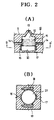
- Figs 2A and 2B illustrate respective sectional views of a write head where liquid metal 20 is utilised in an ink jet printer.
- liquid metal 20 is supplied to ink storage chamber 12.
- the liquid metal is a compound consisting of indium (In) and gallium (Ga), and would also meet the requirement for electric resistance (less than 5 Ohm) which it is impossible to attain with ink. Accordingly, liquid metal serves as an actuator of kinetic energy in lieu of a mass of ink. Therefore, ink 15 is caused to be discharged from the tip of nozzle 13 by virtue of applied kinetic energy generated by operation of the Lorentz force equation via the liquid metal.
- Liquid metal used as above is known to require a temperature not less than a constant value, e.g. 18°C, so as to remain in the liquid state.
- a constant value e.g. 18°C
- a write head for an ink jet printer comprising:
- the heating element is so arranged as indirectly to heat the liquid metal by directly heating the ink. This ensures that the heating of the liquid metal is more homogeneous than might be the case were it heated directly.
- the means for passing an electric current through the liquid metal may comprise a pair of electrodes located on opposite sides of the chamber.
- the means for establishing a magnetic field across the liquid metal may comprise a pair of magnetic bodies located on opposite sides of the chamber.
- the said angle is substantially equal to 90 degrees.
- the temperature sensor and the heating element may be shared by a plurality of chamber/nozzle assemblies.
- the temperature sensor and/or the heating element may be located adjacent to the ink reservoir, adjacent to the lower portion of the chamber, within the ink channel, on a surface of the write head or within the body.
- control means includes a control circuit comprising:
- the present invention also provides a method of controlling a write head in an ink jet printer, in which the write head comprises a chamber having a lower portion containing a quantity of liquid metal and an upper ink reservoir, an ink channel adapted to connect the ink reservoir to an ink cartridge and a nozzle for ejecting ink droplets from the ink reservoir; and means for establishing a magnetic field across the liquid metal and passing an electric current through the liquid metal at an angle to the magnetic field to cause the liquid metal to move and expel an ink droplet from the ink reservoir through the nozzle;
- the liquid metal is heated indirectly by directly heating the ink.
- the write head may be as described above as being in accordance with the invention.
- the present invention also extends to a write head for an ink jet printer adapted to operate according to a method according to the invention.
- the present invention provides an ink jet printer including a write head according to the invention.
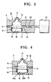
- FIG. 3 there is illustrated one preferred embodiment of a write head of the present invention.
- a plurality of ink storage chamber 12 are provided inside body 11 of a write head 10, which chambers are arranged either separately or collectively linked with each other by respective ink channel 14.
- a nozzle 13 is provided at a portion of an ink storage chamber 12, preferably at the top portion, through which ink droplets are ejected during the operational printing mode.
- the ink storage chamber is supplied with ink from an ink cartridge 23 via ink channel 14.
- a pair of electrodes 16 and 17 are oppositely located in the body 11, while a pair of magnetic bodies 18 and 19 are arranged at a right angle with respect to the electrodes as is described with reference to Figs. 1 and 2. Also, a liquid metal mass 20 is provided at the bottom of the chamber 12.
- a temperature sensor 21 for indirectly detecting the temperature of the liquid metal mass 20 and a heating element 22 for indirectly heating the liquid metal mass 20 are provided in ink channel 14.
- the heating element 22 heats ink and thus liquid metal mass 20 is indirectly heated by warm ink.
- Temperature sensor 21 and heating device 22 may be embodied in a write head 10 on every nozzle 13, or otherwise solely or collectively installed in groups or blocks as necessary.
- heating element 22 heats ink 15 and thus indirectly warms liquid metal 20, and may be position anywhere enabling heating of liquid metal 20. Any location may be chosen for heating device 22; for instance, any surface area of write head 10, inside ink channel 14 or any sidewall of the ink storage chamber. Additionally, temperature sensor 21 may be located adjacent to liquid metal 20 so as to sense the temperature. Indeed, any location at which a temperature of liquid metal 20 can be sensed directly or indirectly may be chosen for temperature sensor 21; for example, body 11, inner sidewalls adjacent to either storage portion of ink or liquid metal in ink storage chamber 12, ink channel 14 and any surface portion of head 10.
- both the heating element and the temperature sensor may be located adjacent the liquid metal and sense its temperature directly or heat it directly as the case may be, rather than indirectly via the ink.
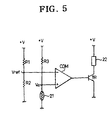
- the electrodes 16 and 17 and magnetic segments 18 and 19 in Figs 3 and 4 are controlled by a control circuit shown in Fig 5.
- the control circuit includes a first voltage divider having two fixed resistor R1 and R2, and a second voltage divider having a fixed resistor R3 and the temperature sensor 21 as an variable resistor, a comparator (COM) having inverting and non-inverting inputs and a transistor (TR) connected to an output of the comparator (COM) for turning on or off the heating element 22.
- a predetermined reference voltage Vref which is voltage divided by first voltage divider, resistors R1 and R2, connected in series to a ground potential, is applied to a non-inverting terminal (-) of comparator COM.
- a potential Va at a varying voltage level generated by second voltage divider, at the junction of resistor R3 and temperature sensor 21, is applied to an inverting terminal (+) of comparator COM.
- the output terminal of comparator COM is connected to the base electrode of transistor TR, the emitter electrode of which is grounded and the collector electrode of which is connected to a power source +V via heating element 22.
- the temperature sensor 21 is a negative temperature coefficient type device and has an internal resistance which increases if the temperature is higher than a predefined temperature (preferably 18°C to 23°C).
- the voltage (Va) of the second voltage divider becomes higher than the reference voltage (Vref) because of the increased resistance of the sensor 21.
- the voltage (Va) is supplied to the comparator and then the comparator outputs a high level signal to the transistor to turn on the heating element 22.
- the internal resistance of the sensor 21 is lowered and the voltage (Va) of the second voltage divider is lower than the reference voltage (Vref) of the first voltage divider, so that the comparator outputs a low level signal to the transistor to turn off the heating element 22. Accordingly, the liquid metal can be maintained in the liquid phase.
- the predefined temperature is preferably in the range of 0°-5°C higher than the metal's melting point.
- heating element 22 dissipates heats, and the temperature of liquid metal 20 increases.
- Fig 6 is a block diagram of a portion of the circuitry of an ink jet printer.
- the circuit shown in Fig 6 incorporates a temperature sensor 21 for sensing the temperature of ink 15; a converter 21B for converting the varying resistance of temperature sensor 21 into a voltage level; a controller 30 for controlling the overall operation of the circuitry in the printer; a memory device 31, for supplying prestored data to the controller, which device may be internal or external; a heating element 22;and a driving circuit 22B for driving the heating element 22.
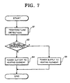
- a flow chart demonstrating the control operation is illustrated. Firstly, a predetermined program is stored into memory device 31. When the circuit is energised then the program is fetched to be executed in controller 30. Temperature sensor 21 senses the temperature and applies the sensed value to a converter 21B. A signal converted in converter 21B is fed to controller 30. (Step 1).
- the controller determines whether the input signal applied from converter 21B, indicative of the temperature of liquid metal 20, is lower than a predetermined temperature which is present at a relevant addresses in memory. (Step 2).
- controller 30 If the input signal represents a temperature below a preset value, then controller 30 outputs a signal to the driving circuit so as to initiate a heat dissipation operation of heating element 22. (Step 3).
- Step 2 if the input signal turned out to indicate a value higher than a preset value, then controller 30 outputs no signal and heating element 22 ceases heat dissipation. (Step 4).
- the present invention holds the temperature of the liquid metal at or above its melting point temperature, allowing the operational temperature of the write head to be properly maintained, thus enhancing the overall performance of the ink jet printer.
Landscapes
- Ink Jet (AREA)
- Particle Formation And Scattering Control In Inkjet Printers (AREA)
Abstract
Description
- The present invention relates to a write head for an ink jet printer, and more particularly, to a write head utilising a liquid metal for ejecting ink droplets.
- As is known the principle in ink jet printers of portraying characters on a recording medium is based upon ejecting individual ink droplets from the nozzle of a write head that is a component part of the printer. The ink drops are ejected from the nozzle under the influence of a control means in the printer. Characters and/or graphic patterns are typically constructed on a grid-like matrix on the recording medium by co-ordinating the ejection of individual droplets and the relative motion between the recording medium and the write head. The operational reliability and the quality of the recording are highly dependent on the uniformity of the droplet ejection, ie the individual droplets ejected by a drive pulse must leave the nozzle of the write head with the same speed.
- Conventionally, a bubble jet printer includes a write head with a heating device for suddenly heating the ink in the region of an ink channel so as to form an ink vapour bubble. Bubbling of the ink caused by a heating device in turn causes ejection of ink from the nozzle. A heating device of the type described above serves as a heating element for heating the ink.
- It is known from US Patent Number 5,182,578 to provide a heating device for warming the ink in an ink channel arranged in the write head of an ink jet printer. The heating device includes a heating element and a temperature sensor arranged on a write head carrier as well as a voltage regulator component. The heating element is supplied with a constant load current via a regulating circuit until an adjustable operating temperature is reached.
- Owing to the frequency of heating cycles for the ink, the innate characteristics of the ink are detrimentally affected. This causes the expected life span of the write head to be short lived as well as that of a heating element itself. As a result, a control means comprising a temperature sensor and a heating element which serves as a heating device for warming and controlling the temperature of the ink does not guarantee reliable regulation of temperature.
- In view of the above, and referring to Figs 1A and 1B, a detailed explanation of the conventionally employed scheme will now be described.
Ink storage chamber 12 is provided inside thebody 11 of a writehead 10 in a conventional ink printer. Anozzle 13 which ejects individual ink droplets is provided at the central area of the top surface of the ink storage chamber. A couple of ink channels arranged opposite each other supply ink from an outside ink cartridge (not shown) to inside theink storage chamber 12. - A pair of
electrodes - The ejection of individual ink droplets from the tip of
nozzle 13 in writehead 20 is subject to the influence of the Lorentz force equation. Thus the magnitude of the force applied to ink in the path of magnetic flux lines derived from the magnetic bodies is determined by Fleming's left-hand rule. Ink is forced to move perpendicular to the directions of the magnetic flux lines formed betweenmagnetic substances electrodes 16 and 17 (usually supplied with a constant current). - The influence of the electric resistance of
ink 15 utilised in the construction of such a write head mechanism is critical for complete droplet ejection. The electric resistance should be lower than 5 Ohm, but this is unattainable in reality. - It has been suggested that a diaphragm may be employed, for example a piezoelectric material, so that
ink 15 is ejected indirectly by the diaphragm. Liquid metal has also been proposed in lieu of a diaphragm and US Patent No. 4,845,517 discloses a write head for an ink jet printer employing a liquid metal as an ejector. - Figs 2A and 2B illustrate respective sectional views of a write head where
liquid metal 20 is utilised in an ink jet printer. - In this configuration, a predetermined quantity of
liquid metal 20 is supplied toink storage chamber 12. The liquid metal is a compound consisting of indium (In) and gallium (Ga), and would also meet the requirement for electric resistance (less than 5 Ohm) which it is impossible to attain with ink. Accordingly, liquid metal serves as an actuator of kinetic energy in lieu of a mass of ink. Therefore,ink 15 is caused to be discharged from the tip ofnozzle 13 by virtue of applied kinetic energy generated by operation of the Lorentz force equation via the liquid metal. - Liquid metal used as above is known to require a temperature not less than a constant value, e.g. 18°C, so as to remain in the liquid state. As a result, normal operation of portraying characters and/or graphics on a recording medium is highly dependent on the temperature of liquid metal since below a melting point temperature, the liquid metal remains solid. This often hinders the normal operational mode of an ink jet printer.
- Therefore it is an object of the present invention to provide a write head control device for an ink jet printer utilising a liquid metal in which the liquid metal is maintained in the liquid state.
- To achieve these and other objects, there is provided a write head for an ink jet printer comprising:
- a chamber having a lower portion containing a quantity of liquid metal and an upper ink reservoir, an ink channel adapted to connect the ink reservoir to an ink cartridge and a nozzle for ejecting ink droplets from the ink reservoir;
- means for establishing a magnetic field across the liquid metal and passing an electric current through the liquid metal at an angle to the magnetic field to cause the liquid metal to move and expel an ink droplet from the ink reservoir through the nozzle;
- a temperature sensor for sensing the temperature at a predetermined position on the write head;
- a heating element for heating the liquid metal; and
- control means for controlling the heating element so as to maintain the temperature of the liquid metal above its melting point.
- Preferably, the heating element is so arranged as indirectly to heat the liquid metal by directly heating the ink. This ensures that the heating of the liquid metal is more homogeneous than might be the case were it heated directly.
- The means for passing an electric current through the liquid metal may comprise a pair of electrodes located on opposite sides of the chamber. The means for establishing a magnetic field across the liquid metal may comprise a pair of magnetic bodies located on opposite sides of the chamber.
- Preferably, to maximise the Lorentz force on the liquid metal, the said angle is substantially equal to 90 degrees.
- The temperature sensor and the heating element may be shared by a plurality of chamber/nozzle assemblies.
- The temperature sensor and/or the heating element may be located adjacent to the ink reservoir, adjacent to the lower portion of the chamber, within the ink channel, on a surface of the write head or within the body.
- Preferably, the control means includes a control circuit comprising:
- a first pair of voltage dividing resistors connected in series, for supplying a reference voltage at a constant level from a junction node;
- a second pair of voltage dividing means consisting of a resistor and the temperature sensor, connected in series, for supplying a varying voltage;
- a comparator receiving the reference voltage at its non-inverting input terminal and the said varying voltage at its inverting input terminal;
- a transistor having a base electrode receiving the output of the comparator, an emitter electrode connected to ground potential and a collector electrode coupled to a power source via the heating element.
- The present invention also provides a method of controlling a write head in an ink jet printer, in which the write head comprises a chamber having a lower portion containing a quantity of liquid metal and an upper ink reservoir, an ink channel adapted to connect the ink reservoir to an ink cartridge and a nozzle for ejecting ink droplets from the ink reservoir; and means for establishing a magnetic field across the liquid metal and passing an electric current through the liquid metal at an angle to the magnetic field to cause the liquid metal to move and expel an ink droplet from the ink reservoir through the nozzle;
-
- the method comprising:
- sensing the temperature at a predetermined position on the write head;
- heating the liquid metal when the said temperature falls below a first predetermined value; and
- ceasing to heat the ink when the said temperature rises above a second predetermined value, so as to maintain the temperature of the liquid metal above its melting point.
- Preferably, the liquid metal is heated indirectly by directly heating the ink.
- The write head may be as described above as being in accordance with the invention.
- The present invention also extends to a write head for an ink jet printer adapted to operate according to a method according to the invention.
- Finally, the present invention provides an ink jet printer including a write head according to the invention.
- A more complete appreciation of the invention, and many of its attendant advantages, will become apparent as the same becomes better understood by reference to the following detailed description of preferred embodiments when considered in conjunction with the accompanying drawings in which like reference numerals and symbols indicate the same or similar components and in which:
- Fig 1A is a schematic sectional view illustrating a conventional write head in an ink jet printer employing a sole ink storage chamber;
- Fig 1B is an enlarged sectional view of the write head, taken along the line A - A in Fig 1A;
- Fig 2A is a schematic sectional view of a conventional a write head in an ink jet printer utilising a liquid metal;
- Fig 2B is an enlarged sectional view of the write head, taken along the line B - B in Fig 2B;
- Fig 3 is a schematic section view of one preferred embodiment of a write head according to the present invention;
- Fig 4 is a schematic sectional view of another preferred embodiment of a write head according to the present invention;
- Fig 5 is a schematic circuit diagram of a driving circuit of a preferred embodiment of the present invention;
- Fig 6 is a block diagram illustrating a portion of the circuitry of an ink jet printer incorporating the driving circuit of Fig 5; and
- Fig 7 is flow chart illustrating the control operation of a circuit as shown in Fig 6.
- Referring to Fig. 3, there is illustrated one preferred embodiment of a write head of the present invention. A plurality of
ink storage chamber 12 are provided insidebody 11 of awrite head 10, which chambers are arranged either separately or collectively linked with each other byrespective ink channel 14. - When the construction is such that a plurality of linked ink channels are present, either a single ink storage chamber of mass storage capability or isolated ink storage chambers would be used as necessary. A
nozzle 13 is provided at a portion of anink storage chamber 12, preferably at the top portion, through which ink droplets are ejected during the operational printing mode. The ink storage chamber is supplied with ink from anink cartridge 23 viaink channel 14. - A pair of
electrodes body 11, while a pair ofmagnetic bodies liquid metal mass 20 is provided at the bottom of thechamber 12. - According to the present invention, a
temperature sensor 21 for indirectly detecting the temperature of theliquid metal mass 20 and aheating element 22 for indirectly heating theliquid metal mass 20 are provided inink channel 14. Theheating element 22 heats ink and thusliquid metal mass 20 is indirectly heated by warm ink. -
Temperature sensor 21 andheating device 22 may be embodied in awrite head 10 on everynozzle 13, or otherwise solely or collectively installed in groups or blocks as necessary. - In Fig. 3,
heating element 22heats ink 15 and thus indirectly warmsliquid metal 20, and may be position anywhere enabling heating ofliquid metal 20. Any location may be chosen forheating device 22; for instance, any surface area ofwrite head 10, insideink channel 14 or any sidewall of the ink storage chamber. Additionally,temperature sensor 21 may be located adjacent toliquid metal 20 so as to sense the temperature. Indeed, any location at which a temperature ofliquid metal 20 can be sensed directly or indirectly may be chosen fortemperature sensor 21; for example,body 11, inner sidewalls adjacent to either storage portion of ink or liquid metal inink storage chamber 12,ink channel 14 and any surface portion ofhead 10. - As can be seen from Fig. 4, another preferred embodiment of the present invention, both the heating element and the temperature sensor may be located adjacent the liquid metal and sense its temperature directly or heat it directly as the case may be, rather than indirectly via the ink.
- The
electrodes magnetic segments temperature sensor 21 as an variable resistor, a comparator (COM) having inverting and non-inverting inputs and a transistor (TR) connected to an output of the comparator (COM) for turning on or off theheating element 22. A predetermined reference voltage Vref which is voltage divided by first voltage divider, resistors R1 and R2, connected in series to a ground potential, is applied to a non-inverting terminal (-) of comparator COM. A potential Va at a varying voltage level generated by second voltage divider, at the junction of resistor R3 andtemperature sensor 21, is applied to an inverting terminal (+) of comparator COM. - The output terminal of comparator COM is connected to the base electrode of transistor TR, the emitter electrode of which is grounded and the collector electrode of which is connected to a power source +V via
heating element 22. Preferably, thetemperature sensor 21 is a negative temperature coefficient type device and has an internal resistance which increases if the temperature is higher than a predefined temperature (preferably 18°C to 23°C). - When the
sensor 21 detects a temperature lower than 18°C which is the melting point of the liquid metal, the voltage (Va) of the second voltage divider becomes higher than the reference voltage (Vref) because of the increased resistance of thesensor 21. Thus the voltage (Va) is supplied to the comparator and then the comparator outputs a high level signal to the transistor to turn on theheating element 22. - When the temperature detected by the
sensor 21 is higher than the predefined temperature, the internal resistance of thesensor 21 is lowered and the voltage (Va) of the second voltage divider is lower than the reference voltage (Vref) of the first voltage divider, so that the comparator outputs a low level signal to the transistor to turn off theheating element 22. Accordingly, the liquid metal can be maintained in the liquid phase. The predefined temperature is preferably in the range of 0°-5°C higher than the metal's melting point. - As a result, if transistor turns on, then heating
element 22 dissipates heats, and the temperature ofliquid metal 20 increases. - When the temperature of
liquid metal 20 exceeds a predetermined value, then potential Va becomes lower due to decreased internal resistance oftemperature sensor 21 thereby enabling comparator COM to generate a signal of the low level, which in turn cuts off the electrical conduction path in transistor TR. At this moment,heating element 22 ceases a heat dissipation. With the above described operation, a constant temperature is maintained in theliquid metal 20. - Fig 6 is a block diagram of a portion of the circuitry of an ink jet printer. The circuit shown in Fig 6 incorporates a
temperature sensor 21 for sensing the temperature ofink 15; a converter 21B for converting the varying resistance oftemperature sensor 21 into a voltage level; acontroller 30 for controlling the overall operation of the circuitry in the printer; amemory device 31, for supplying prestored data to the controller, which device may be internal or external; aheating element 22;and adriving circuit 22B for driving theheating element 22. - Referring to Fig 7, a flow chart demonstrating the control operation is illustrated. Firstly, a predetermined program is stored into
memory device 31. When the circuit is energised then the program is fetched to be executed incontroller 30.Temperature sensor 21 senses the temperature and applies the sensed value to a converter 21B. A signal converted in converter 21B is fed tocontroller 30. (Step 1). - The controller determines whether the input signal applied from converter 21B, indicative of the temperature of
liquid metal 20, is lower than a predetermined temperature which is present at a relevant addresses in memory. (Step 2). - If the input signal represents a temperature below a preset value, then
controller 30 outputs a signal to the driving circuit so as to initiate a heat dissipation operation ofheating element 22. (Step 3). - In
Step 2, however, if the input signal turned out to indicate a value higher than a preset value, thencontroller 30 outputs no signal andheating element 22 ceases heat dissipation. (Step 4). - The sequential operations as above enable the liquid metal to hold its temperature at a relatively constant value, not less than its critical melting point temperature.
- As disclosed above, the present invention holds the temperature of the liquid metal at or above its melting point temperature, allowing the operational temperature of the write head to be properly maintained, thus enhancing the overall performance of the ink jet printer.
Claims (19)
- A write head for an ink jet printer comprising:a chamber having a lower portion containing a quantity of liquid metal and an upper ink reservoir, an ink channel adapted to connect the ink reservoir to an ink cartridge and a nozzle for ejecting ink droplets from the ink reservoir;means for establishing a magnetic field across the liquid metal and passing an electric current through the liquid metal at an angle to the magnetic field to cause the liquid metal to move and expel an ink droplet from the ink reservoir through the nozzle;a temperature sensor for sensing the temperature at a predetermined position on the write head;a heating element for heating the liquid metal; andcontrol means for controlling the heating element so as to maintain the temperature of the liquid metal above its melting point.
- A write head according to claim 1 in which the heating element is so arranged as indirectly to heat the liquid metal by directly heating the ink.
- A write head according to claim 1 or claim 2 in which the means for passing an electric current through the liquid metal comprises a pair of electrodes located on opposite sides of the chamber.
- A write head according to any preceding claim in which the means for establishing a magnetic field across the liquid metal comprises a pair of magnetic bodies located on opposite sides of the chamber.
- A write head according to any preceding claim in which the said angle is substantially equal to 90 degrees.
- A write head according to any preceding claim in which the temperature sensor and the heating element are shared by a plurality of chamber/nozzle assemblies.
- A write head according to any preceding claim in which the temperature sensor and/or the heating element are located adjacent to the ink reservoir.
- A write head device according to any one of claims 1-6 in which the temperature sensor and/or the heating element are located adjacent to the lower portion of the chamber.
- A write head according to any one of claims 1-6 in which the temperature sensor and/or the heating element are located within the ink channel.
- A write head according to any preceding claim in which the temperature sensor and/or the heating element are located on a surface of the write head.
- A write head according to any one of claims 1-9 in which the temperature sensor and/or the heating element are located within the body.
- A write head according to any preceding claim in which the control means includes a control circuit comprising:a first pair of voltage dividing resistors connected in series, for supplying a reference voltage at a constant level from a junction node;a second pair of voltage dividing means consisting of a resistor and the temperature sensor, connected in series, for supplying a varying voltage;a comparator receiving the reference voltage at its non-inverting input terminal and the said varying voltage at its inverting input terminal;a transistor having a base electrode receiving the output of the comparator, an emitter electrode connected to ground potential and a collector electrode coupled to a power source via the heating element.
- A write head for an ink jet printer as described herein with reference to and as illustrated in Figs. 3 and 5-7 of the accompanying drawings.
- A write head for an ink jet printer as described herein with reference to and as illustrated in Figs. 4-7 of the accompanying drawings.
- A method of controlling a write head in an ink jet printer, in which the write head comprises a chamber having a lower portion containing a quantity of liquid metal and an upper ink reservoir, an ink channel adapted to connect the ink reservoir to an ink cartridge and a nozzle for ejecting ink droplets from the ink reservoir; and means for establishing a magnetic field across the liquid metal and passing an electric current through the liquid metal at an angle to the magnetic field to cause the liquid metal to move and expel an ink droplet from the ink reservoir through the nozzle;the method comprising:sensing the temperature at a predetermined position on the write head;heating the liquid metal when the said temperature falls below a first predetermined value; andceasing to heat the ink when the said temperature rises above a second predetermined value, so as to maintain the temperature of the liquid metal above its melting point.
- A method according to claim 15 in which the liquid metal is heated indirectly by directly heating the ink.
- A method according to claim 15 or claim 16 in which the write head is as claimed in any one of claims 1-14.
- A write head for an ink jet printer adapted to operate according to the method of claim 15 or claim 16.
- An ink jet printer including a write head according to any one of claims 1-14 or 18.
Applications Claiming Priority (2)
| Application Number | Priority Date | Filing Date | Title |
|---|---|---|---|
| KR1019950009586A KR0147902B1 (en) | 1995-04-24 | 1995-04-24 | Control apparatus and method of ink jet printer head using liquid metal |
| KR9509586 | 1995-04-24 |
Publications (3)
| Publication Number | Publication Date |
|---|---|
| EP0739733A2 true EP0739733A2 (en) | 1996-10-30 |
| EP0739733A3 EP0739733A3 (en) | 1997-06-25 |
| EP0739733B1 EP0739733B1 (en) | 2000-07-05 |
Family
ID=19412756
Family Applications (1)
| Application Number | Title | Priority Date | Filing Date |
|---|---|---|---|
| EP96106437A Expired - Lifetime EP0739733B1 (en) | 1995-04-24 | 1996-04-24 | Write head control device and method |
Country Status (5)
| Country | Link |
|---|---|
| US (1) | US5831643A (en) |
| EP (1) | EP0739733B1 (en) |
| JP (1) | JPH08318626A (en) |
| KR (1) | KR0147902B1 (en) |
| DE (1) | DE69609113T2 (en) |
Families Citing this family (17)
| Publication number | Priority date | Publication date | Assignee | Title |
|---|---|---|---|---|
| US6540316B1 (en) * | 1999-06-04 | 2003-04-01 | Canon Kabushiki Kaisha | Liquid discharge head and liquid discharge apparatus |
| DE60016503T2 (en) * | 1999-06-04 | 2005-12-15 | Canon K.K. | Liquid ejection head, liquid ejection device and method of manufacturing a liquid ejection head |
| JP3880411B2 (en) * | 2001-01-31 | 2007-02-14 | キヤノン株式会社 | Recording device |
| US7730746B1 (en) | 2005-07-14 | 2010-06-08 | Imaging Systems Technology | Apparatus to prepare discrete hollow microsphere droplets |
| US7802866B2 (en) * | 2006-06-19 | 2010-09-28 | Canon Kabushiki Kaisha | Recording head that detects temperature information corresponding to a plurality of electro-thermal transducers on the recording head and recording apparatus using the recording head |
| JP2009190380A (en) * | 2008-02-18 | 2009-08-27 | Riso Kagaku Corp | Printing device |
| US8220896B2 (en) * | 2009-03-17 | 2012-07-17 | Xerox Corporation | Printhead de-prime system and method for solid ink systems |
| JP5679825B2 (en) * | 2010-01-21 | 2015-03-04 | キヤノン株式会社 | Liquid discharge apparatus and liquid discharge head abnormality detection method |
| US9559162B2 (en) | 2013-06-19 | 2017-01-31 | Globalfoundries Inc. | Thermoresistance sensor structure for integrated circuits and method of making |
| CN104425207A (en) * | 2013-08-20 | 2015-03-18 | 中国科学院理化技术研究所 | Multi-die electronic direct writing ballpoint pen |
| JP6448227B2 (en) | 2014-06-19 | 2019-01-09 | キヤノン株式会社 | Element substrate and liquid discharge head |
| JP6448228B2 (en) * | 2014-06-19 | 2019-01-09 | キヤノン株式会社 | Element substrate and liquid discharge head |
| CN107414080B (en) * | 2016-05-23 | 2024-04-16 | 中国科学院理化技术研究所 | Liquid metal 3D prints shower nozzle device and is equipped with device's 3D printer |
| MX2019010002A (en) * | 2017-02-24 | 2019-12-16 | Jfe Steel Corp | Continuous molten metal plating apparatus and molten metal plating method using said apparatus. |
| US10870273B2 (en) | 2017-07-18 | 2020-12-22 | Hewlett-Packard Development Company, L.P. | Dies including strain gauge sensors and temperature sensors |
| DE102020108317A1 (en) * | 2020-03-26 | 2021-09-30 | Phoenix Contact Gmbh & Co. Kg | Inkjet printhead |
| US11400714B2 (en) * | 2020-12-22 | 2022-08-02 | Xerox Corporation | Method for magnetohydrodynamic (MHD) printhead/nozzle reuse |
Family Cites Families (4)
| Publication number | Priority date | Publication date | Assignee | Title |
|---|---|---|---|---|
| US4845517A (en) * | 1988-01-11 | 1989-07-04 | Am International, Inc. | Droplet deposition apparatus |
| WO1990000115A1 (en) * | 1988-06-29 | 1990-01-11 | Siemens Aktiengesellschaft | Arrangement for warming up the ink in the write head of an ink printing machine |
| US5560543A (en) * | 1994-09-19 | 1996-10-01 | Board Of Regents, The University Of Texas System | Heat-resistant broad-bandwidth liquid droplet generators |
| US5598200A (en) * | 1995-01-26 | 1997-01-28 | Gore; David W. | Method and apparatus for producing a discrete droplet of high temperature liquid |
-
1995
- 1995-04-24 KR KR1019950009586A patent/KR0147902B1/en not_active Expired - Fee Related
-
1996
- 1996-04-24 US US08/639,091 patent/US5831643A/en not_active Expired - Fee Related
- 1996-04-24 DE DE69609113T patent/DE69609113T2/en not_active Expired - Fee Related
- 1996-04-24 EP EP96106437A patent/EP0739733B1/en not_active Expired - Lifetime
- 1996-04-24 JP JP8127739A patent/JPH08318626A/en active Pending
Also Published As
| Publication number | Publication date |
|---|---|
| EP0739733B1 (en) | 2000-07-05 |
| JPH08318626A (en) | 1996-12-03 |
| EP0739733A3 (en) | 1997-06-25 |
| KR960037288A (en) | 1996-11-19 |
| DE69609113D1 (en) | 2000-08-10 |
| DE69609113T2 (en) | 2001-03-22 |
| US5831643A (en) | 1998-11-03 |
| KR0147902B1 (en) | 1998-08-17 |
Similar Documents
| Publication | Publication Date | Title |
|---|---|---|
| EP0739733B1 (en) | Write head control device and method | |
| EP0838334B1 (en) | Ink jet recording apparatus having temperature control function | |
| US4719472A (en) | Ink jet recording head | |
| US6729707B2 (en) | Self-calibration of power delivery control to firing resistors | |
| US4007684A (en) | Ink liquid warmer for ink jet system printer | |
| KR970011234B1 (en) | Ink-jet recording head and ink-jet recording apparatus | |
| US5264865A (en) | Ink jet recording method and apparatus utilizing temperature dependent, pre-discharge, meniscus retraction | |
| US4514737A (en) | Printing head driving apparatus | |
| EP0752313B1 (en) | Ink-jet print head thermal working condition stabilization method | |
| US7625056B2 (en) | Device and method for driving jetting head | |
| EP0763429B1 (en) | Ink jet printhead heating | |
| EP1151868A2 (en) | Method for using highly energetic droplet firing events to improve droplet ejection reliability | |
| JPS62111750A (en) | Ink jet recorder | |
| JPH02162054A (en) | Temperature controller for ink jet printer | |
| US5881646A (en) | Method and apparatus for image recording by emitting evaporated ink onto a recording medium | |
| EP0758584A2 (en) | Ink-jet printer using ink containing pigment particles | |
| US6886903B2 (en) | Determination of turn-on energy for a printhead | |
| JPH09150505A (en) | Inkjet recording head drive circuit | |
| JPH03218845A (en) | Ink jet printer | |
| JPH02151447A (en) | inkjet recording device | |
| CA2296908C (en) | Ink jet recording apparatus having temperature control function | |
| JPH0939237A (en) | Inkjet head drive power supply circuit | |
| JPH04307258A (en) | inkjet printer | |
| JPS6290250A (en) | Temperature controller of ink jet printer | |
| JPH05185635A (en) | Protection circuit of thermal head |
Legal Events
| Date | Code | Title | Description |
|---|---|---|---|
| PUAI | Public reference made under article 153(3) epc to a published international application that has entered the european phase |
Free format text: ORIGINAL CODE: 0009012 |
|
| AK | Designated contracting states |
Kind code of ref document: A2 Designated state(s): DE FR GB |
|
| PUAL | Search report despatched |
Free format text: ORIGINAL CODE: 0009013 |
|
| AK | Designated contracting states |
Kind code of ref document: A3 Designated state(s): DE FR GB |
|
| 17P | Request for examination filed |
Effective date: 19960424 |
|
| R17P | Request for examination filed (corrected) |
Effective date: 19980109 |
|
| 17Q | First examination report despatched |
Effective date: 19990223 |
|
| GRAG | Despatch of communication of intention to grant |
Free format text: ORIGINAL CODE: EPIDOS AGRA |
|
| GRAG | Despatch of communication of intention to grant |
Free format text: ORIGINAL CODE: EPIDOS AGRA |
|
| GRAH | Despatch of communication of intention to grant a patent |
Free format text: ORIGINAL CODE: EPIDOS IGRA |
|
| GRAH | Despatch of communication of intention to grant a patent |
Free format text: ORIGINAL CODE: EPIDOS IGRA |
|
| GRAA | (expected) grant |
Free format text: ORIGINAL CODE: 0009210 |
|
| AK | Designated contracting states |
Kind code of ref document: B1 Designated state(s): DE FR GB |
|
| REF | Corresponds to: |
Ref document number: 69609113 Country of ref document: DE Date of ref document: 20000810 |
|
| ET | Fr: translation filed | ||
| PLBE | No opposition filed within time limit |
Free format text: ORIGINAL CODE: 0009261 |
|
| STAA | Information on the status of an ep patent application or granted ep patent |
Free format text: STATUS: NO OPPOSITION FILED WITHIN TIME LIMIT |
|
| 26N | No opposition filed | ||
| REG | Reference to a national code |
Ref country code: GB Ref legal event code: IF02 |
|
| PGFP | Annual fee paid to national office [announced via postgrant information from national office to epo] |
Ref country code: DE Payment date: 20070419 Year of fee payment: 12 |
|
| PGFP | Annual fee paid to national office [announced via postgrant information from national office to epo] |
Ref country code: GB Payment date: 20070418 Year of fee payment: 12 |
|
| PGFP | Annual fee paid to national office [announced via postgrant information from national office to epo] |
Ref country code: FR Payment date: 20080312 Year of fee payment: 13 |
|
| GBPC | Gb: european patent ceased through non-payment of renewal fee |
Effective date: 20080424 |
|
| PG25 | Lapsed in a contracting state [announced via postgrant information from national office to epo] |
Ref country code: DE Free format text: LAPSE BECAUSE OF NON-PAYMENT OF DUE FEES Effective date: 20081101 |
|
| PG25 | Lapsed in a contracting state [announced via postgrant information from national office to epo] |
Ref country code: GB Free format text: LAPSE BECAUSE OF NON-PAYMENT OF DUE FEES Effective date: 20080424 |
|
| REG | Reference to a national code |
Ref country code: FR Ref legal event code: ST Effective date: 20091231 |
|
| PG25 | Lapsed in a contracting state [announced via postgrant information from national office to epo] |
Ref country code: FR Free format text: LAPSE BECAUSE OF NON-PAYMENT OF DUE FEES Effective date: 20091222 |