EP0739290B1 - A vessel for production and/or loading/unloading and transport of hydrocarbons from offshore fields, and/or for carrying out well operations - Google Patents
A vessel for production and/or loading/unloading and transport of hydrocarbons from offshore fields, and/or for carrying out well operations Download PDFInfo
- Publication number
- EP0739290B1 EP0739290B1 EP95908395A EP95908395A EP0739290B1 EP 0739290 B1 EP0739290 B1 EP 0739290B1 EP 95908395 A EP95908395 A EP 95908395A EP 95908395 A EP95908395 A EP 95908395A EP 0739290 B1 EP0739290 B1 EP 0739290B1
- Authority
- EP
- European Patent Office
- Prior art keywords
- vessel
- loading
- buoy
- stern
- deck
- Prior art date
- Legal status (The legal status is an assumption and is not a legal conclusion. Google has not performed a legal analysis and makes no representation as to the accuracy of the status listed.)
- Expired - Lifetime
Links
- 238000004519 manufacturing process Methods 0.000 title claims abstract description 11
- 229930195733 hydrocarbon Natural products 0.000 title claims abstract description 6
- 150000002430 hydrocarbons Chemical class 0.000 title claims abstract description 6
- 230000008878 coupling Effects 0.000 claims abstract description 6
- 238000010168 coupling process Methods 0.000 claims abstract description 6
- 238000005859 coupling reaction Methods 0.000 claims abstract description 6
- 238000012423 maintenance Methods 0.000 claims description 10
- 238000000034 method Methods 0.000 claims description 8
- 241000237519 Bivalvia Species 0.000 claims 1
- 235000020639 clam Nutrition 0.000 claims 1
- 239000003129 oil well Substances 0.000 description 4
- 238000012546 transfer Methods 0.000 description 3
- 230000000694 effects Effects 0.000 description 2
- 238000012544 monitoring process Methods 0.000 description 2
- 238000004873 anchoring Methods 0.000 description 1
- 238000009434 installation Methods 0.000 description 1
- 238000012545 processing Methods 0.000 description 1
- 239000007858 starting material Substances 0.000 description 1
- 238000012360 testing method Methods 0.000 description 1
- 230000000699 topical effect Effects 0.000 description 1
- XLYOFNOQVPJJNP-UHFFFAOYSA-N water Substances O XLYOFNOQVPJJNP-UHFFFAOYSA-N 0.000 description 1
- 239000003643 water by type Substances 0.000 description 1
Images


Classifications
-
- B—PERFORMING OPERATIONS; TRANSPORTING
- B63—SHIPS OR OTHER WATERBORNE VESSELS; RELATED EQUIPMENT
- B63B—SHIPS OR OTHER WATERBORNE VESSELS; EQUIPMENT FOR SHIPPING
- B63B27/00—Arrangement of ship-based loading or unloading equipment for cargo or passengers
- B63B27/24—Arrangement of ship-based loading or unloading equipment for cargo or passengers of pipe-lines
-
- B—PERFORMING OPERATIONS; TRANSPORTING
- B63—SHIPS OR OTHER WATERBORNE VESSELS; RELATED EQUIPMENT
- B63B—SHIPS OR OTHER WATERBORNE VESSELS; EQUIPMENT FOR SHIPPING
- B63B22/00—Buoys
- B63B22/02—Buoys specially adapted for mooring a vessel
- B63B22/021—Buoys specially adapted for mooring a vessel and for transferring fluids, e.g. liquids
- B63B22/026—Buoys specially adapted for mooring a vessel and for transferring fluids, e.g. liquids and with means to rotate the vessel around the anchored buoy
-
- B—PERFORMING OPERATIONS; TRANSPORTING
- B63—SHIPS OR OTHER WATERBORNE VESSELS; RELATED EQUIPMENT
- B63B—SHIPS OR OTHER WATERBORNE VESSELS; EQUIPMENT FOR SHIPPING
- B63B22/00—Buoys
- B63B22/02—Buoys specially adapted for mooring a vessel
- B63B2022/028—Buoys specially adapted for mooring a vessel submerged, e.g. fitting into ship-borne counterpart with or without rotatable turret, or being releasably connected to moored vessel
Definitions
- the invention relates to a vessel for use in production or transport of hydrocarbons from offshore fields. Further, the invention relates to a method for loading of oil from a loading haze which is connected to an underwater buoy and which, for connection, is pulled up onto the deck of a vessel and connected to a loading manifold on the deck.
- a vessel of the introductorily stated type of claim 1 which, according to the invention, is characterized in that the vessel near to its forward end comprises a submerged receiving space for receiving an underwater buoy, and a service shaft extending between the receiving space and the deck of the vessel, and that the vessel further, at its stern on the deck, comprises a coupling head and equipment for connection of a hose for loading/unloading of oil.
- An advantageous embodiment of the vessel according to the invention is characterized in that its stern in plan view has a pointed, rounded shape (bow shape).
- bow shape pointed, rounded shape
- An additional advantage of this hull shape is achieved if a load transfer between two vessels is to be undertaken. If the vessels during the load transfer should get in contact with each other, possible damages will be substantially reduced compared to if the vessel has a traditional, transverse stern which the rearwardly located vessel runs into.
- the placing of loading/unloading equipment at the stern of the vessel has an additional advantage if the vessel operates as a traditional shuttle tanker and is to load from a submerged hose, for example in connection with a buoy of the UKOLS type. In such situations the vessel will be lying with the bow against the wind and connect itself to the loading hose with the stern to leeward.
- a method of the introductorily stated type of claim 7 which, according to the invention, is characterized in that the loading manifold is placed at the stern of the vessel, that the ship prior to the connection is positioned with the bow towards the wind at the windward side of the buoy, and that the vessel is moved from this position so that its stern gets into position to be connected to the loading hose.
- the wheelhouse of the vessel and its engine room can be placed quite at the bow portion of the vessel.
- the service shaft up from the receiving space of the vessel then will be placed just behind the wheelhouse, and thus will be under the lee of the wheelhouse.
- the vessel Since the vessel is to be able to change between different fields of activity, it is preferable that the whole process installation is divided into smaller portable modules.
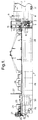
- a vessel 1 according to the invention is schematically shown in side view in Fig. 1.
- a submerged, downwardly open receiving space 2 for receiving an underwater buoy 3 at the forward end of the vessel there is arranged a submerged, downwardly open receiving space 2 for receiving an underwater buoy 3, and a service shaft 4 extends between the receiving space 2 and the deck 5 of the vessel.
- the arrangement is designed such that a submerged buoy for loading/unloading of hydrocarbons can be pulled up and secured in the receiving space, as further shown and described in the Norwegian patent applications Nos. 923814 - 923816, and further such that a buoy which is arranged to cooperate with a swivel unit arranged at the lower end of the shaft, can be pulled up and secured, for use of the vessel as a production vessel, as further shown and described in the Norwegian patent applications Nos. 922043 - 922045. Reference is here made to said applications, for a further description of the topical embodiments.
- the wheelhouse 6 of the vessel is placed near to the bow 7 of the vessel, and further the engine room 8 with the diesel-electric main machinery thereof is placed below the wheelhouse.
- the service shaft 4, which extends between the buoy 3 and the deck 5 of the vessel, is placed just behind the wheelhouse, so that crew which is to go down into the shaft, will be in lee behind the wheelhouse.
- a loading manifold/swivel 9 for connection to the buoy 3, and also a connecting pipe with an oil pipe valve 10.
- monitoring means 11 e.g. TV cameras
- a shutter 12 for shutting-off the shaft 4 over the receiving space
- a guide means 13 for use in connection with pulling-up of the buoy.
- a pulling winch 14 On the deck there is further shown to be arranged a pulling winch 14, a storage unit 15 and a service crane 16 for use in connection with i.a. maintenance.
- a pair of bow propellers 17 In the bow of the vessel there is arranged a pair of bow propellers 17.
- Fig. 1 shows a coupling head in the form of a loading manifold 20 with a swivel, a hose windlass 21, a hose handling winch 22 and TV monitoring equipment 23. Further, there are shown a control room 24 and a hydraulics room 25. Additional elements forming part of the loading/unloading equipment at the stern are to be mentioned in connection with Figs. 4-6.
- Process equipment for the processing of oil is arranged on the deck between the forward and the rearward part of the vessel. This equipment is shown in the form of a number of portable modules 26. Between the forward and the rearward part, the vessel contains a number of cargo compartments or tanks 28. In the rearward area there is also shown to be arranged a flare boom 27. The main propeller 29 of the vessel is shown to be connected to an electric driving motor 30.
- Fig. 2 shows an application wherein produced oil from an oil well is supplied to the vessel from a manifold 35 at the sea bed 36, at the same time as maintenance is effected of an oil well 37 which is connected to the manifold 35.
- necessary equipment for carrying out the maintenance operations is arranged at the stern of the vessel, where the equipment by suitable means 38 is guided down to the well head via e.g. a wire or pipeline 39.
- the manifold 35 at the sea bed is connected to the buoy 3 via flexible risers 40.
- the buoy 3 is bottom-anchored by means of a suitable anchor system (not shown in the drawings), so that the buoy also constitutes an anchoring buoy for the vessel.
- This application of the vessel is particularly advantageous when a number of wells 37 are arranged in a circle at the sea bed around the manifold 35, and the distance between the manifold and the wells is essentially equal to the length of the vessel.
- the vessel then can be permanently connected to the manifold 35 via the buoy 3, and produce oil from the manifold, at the same time as maintenance of the different wells can be carried out from the stern of the vessel, the vessel being able to be turned about the buoy as required, so that its stern can be placed over the well of interest. In this manner maintenance/control of bottom-mounted multiphase equipment and process equipment can be carried out during production, which is very advantageous, especially in deep waters.
- the vessel of course also can be used only for production from an oil well via the buoy in the receiving space, or only for well maintenance via the rearward end of the vessel, without combining these operations. Possibly, well maintenance can be carried out via the service shaft 4 and the receiving space 2, with dynamic positioning of the vessel.
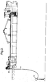
- FIG. 3 shows another application wherein oil is loaded from a loading hose 41 which is connected to an underwater buoy 42, the hose being pulled up onto the deck of the vessel and connected to the loading manifold 20.
- Such buoy loading advantageously is carried out in accordance with the method mentioned in the introduction.
- Oil may also be loaded via a transfer conduit or a riser which is coupled to a loading buoy in the receiving space, where the buoy is of the type which, for example, is mentioned in the aforementioned patent application No. 923815.
- Oil loading also may take place via the stern of the vessel in connection with other types of loading devices, e.g. spar-buoy buoys (spar type loading), buoys floating on the surface of the water, or articulated (buoy) columns.
- other types of loading devices e.g. spar-buoy buoys (spar type loading), buoys floating on the surface of the water, or articulated (buoy) columns.
- the vessel also may be used for carrying out well tests, both via the forward service shaft and from the stern of the vessel, in both cases with dynamic positioning.
- the vessel also may constitute a storage for oil, and according to requirement unload the oil over to e.g. a shuttle tanker by means of a hose connection between the stern of the vessel and the shuttle tanker.
- a guide roller 45 In addition to the elements mentioned above, in the side view of Fig. 4 and in the plan view of Fig. 5 there are shown a guide roller 45, a hydraulic pump station 46, a storage unit 47, a service crane 48, a pulling winch 49, a fairlead 50, bunker line drums 51 and a chain stopper 52.
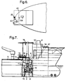
- Fig. 6 shows the poop deck of the vessel where the loading manifold 20 and the hose handling winch 22 are arranged. Further, the Figure shows a manifold control console 53 and a storage unit 54.
- Fig. 7 which shows the forward part of the vessel, the buoy 3 is omitted.
- a steering console 55 arranged on the navigating bridge, and there are also suggested a hydraulic pump station 56 and starter cabinets 57.
- a hydraulic pump station 56 and starter cabinets 57 in other respects reference is made to the aforementioned patent applications, for a further description of the constructive embodiments of the buoy, and the equipment arranged in connection with the receiving space and the service shaft.
Landscapes
- Chemical & Material Sciences (AREA)
- Engineering & Computer Science (AREA)
- Combustion & Propulsion (AREA)
- Mechanical Engineering (AREA)
- Ocean & Marine Engineering (AREA)
- Ship Loading And Unloading (AREA)
- Loading And Unloading Of Fuel Tanks Or Ships (AREA)
- Jib Cranes (AREA)
- Filling Or Discharging Of Gas Storage Vessels (AREA)
Abstract
Description
Claims (7)
- A vessel (1)for use in production or transport of hydrocarbons from offshore fields, characterized in that the vessel near to its forward end comprises a submerged receiving space (2) for receiving an underwater buoy (3), and a service shaft (4) extending between the receiving space and the deck (5) of the vessel, and that the vessel,at its stern on the deck comprises a coupling head and equipment (21,22) for connection of a hose (41) for loading/unloading of oil.
- A vessel according to claim 1, characterized in that its stern in plan view has a pointed, rounded shape (bow shape).
- A vessel according to claim 1 or 2, comprising a wheelhouse (6) and an engine room (8) characterized in that the wheelhouse is placed near to the bow of the vessel, that the engine room with diesel-electric propulsion machinery is placed under the wheelhouse, and that the receiving space (2) for the buoy and the service shaft up from the receiving space are placed just behind the wheelhouse, so that crew which is to go down into the shaft will be in lee behind the wheelhouse.
- A vessel according to any of the clams 1-3, characterized in that equipment for well maintenance is arranged in connection with the service shaft (4).
- A vessel according to any of the claims 1-4, characterized in that equipment for well maintenance is arranged on the deck at the stern of the vessel.
- A vessel according to any of the claims 1-5, characterized in that a swivel unit for coupling of the underwater buoy (3) to a pipe system on the vessel is arranged at the lower end of the service shaft (4), the swivel unit being movably arranged, to be taken away from the shaft and clear the shaft when the swivel is not in use.
- A method for loading of oil from a loading hose (41) which is connected to an underwater buoy (42) and which, for connection, is pulled up onto the deck of a vessel and connected to a loading manifold (20) on the deck, characterized in that the loading manifold is placed at the stern of the vessel, that the ship prior to the connection is positioned with the bow towards the wind at the windward side of the buoy, and that the vessel is moved from this position so that its stern gets into position to be connected to the loading hose.
Applications Claiming Priority (3)
| Application Number | Priority Date | Filing Date | Title |
|---|---|---|---|
| NO940352 | 1994-02-02 | ||
| NO19940352A NO311075B1 (en) | 1994-02-02 | 1994-02-02 | Vessels that can alternate between operating as a production vessel for hydrocarbon production / storage vessels on offshore fields and as shuttle tanks |
| PCT/NO1995/000022 WO1995021091A1 (en) | 1994-02-02 | 1995-02-01 | A vessel for production and/or loading/unloading and transport of hydrocarbons from offshore fields, and/or for carrying out well operations |
Publications (2)
| Publication Number | Publication Date |
|---|---|
| EP0739290A1 EP0739290A1 (en) | 1996-10-30 |
| EP0739290B1 true EP0739290B1 (en) | 1998-12-16 |
Family
ID=19896811
Family Applications (1)
| Application Number | Title | Priority Date | Filing Date |
|---|---|---|---|
| EP95908395A Expired - Lifetime EP0739290B1 (en) | 1994-02-02 | 1995-02-01 | A vessel for production and/or loading/unloading and transport of hydrocarbons from offshore fields, and/or for carrying out well operations |
Country Status (17)
| Country | Link |
|---|---|
| US (1) | US5749758A (en) |
| EP (1) | EP0739290B1 (en) |
| JP (1) | JP4018134B2 (en) |
| KR (1) | KR100397362B1 (en) |
| CN (1) | CN1051518C (en) |
| AU (1) | AU686328B2 (en) |
| BR (1) | BR9506693A (en) |
| CA (1) | CA2182293C (en) |
| DE (1) | DE69506687T2 (en) |
| DK (1) | DK0739290T3 (en) |
| ES (1) | ES2128042T3 (en) |
| FI (1) | FI112056B (en) |
| GB (1) | GB2300836B (en) |
| NO (1) | NO311075B1 (en) |
| PL (1) | PL315775A1 (en) |
| RU (1) | RU2144611C1 (en) |
| WO (1) | WO1995021091A1 (en) |
Families Citing this family (25)
| Publication number | Priority date | Publication date | Assignee | Title |
|---|---|---|---|---|
| NO964979L (en) * | 1996-11-22 | 1998-05-25 | Ship Based Systems As | multipurpose Ship |
| GB9930450D0 (en) * | 1999-12-23 | 2000-02-16 | Eboroil Sa | Subsea well intervention vessel |
| US6364021B1 (en) * | 2000-07-11 | 2002-04-02 | Halliburton Energy Services, Inc. | Well management system and method of operation |
| NO312359B1 (en) * | 2000-07-20 | 2002-04-29 | Statoil Asa | Cargo transfer system from a ship-based production and storage unit to a dynamically positioned tanker |
| US7958938B2 (en) * | 2004-05-03 | 2011-06-14 | Exxonmobil Upstream Research Company | System and vessel for supporting offshore fields |
| BRPI0506432A8 (en) * | 2004-10-15 | 2018-04-24 | Exxonmobil Upstream Res Co | system and method for transporting a cryogenic fluid |
| RU2286904C1 (en) * | 2005-03-22 | 2006-11-10 | Александров Владимир Леонидович | Method of transportation of liquid cargoes in bulk (versions) |
| RU2286915C1 (en) * | 2005-03-22 | 2006-11-10 | Александров Владимир Леонидович | Method of transportation of liquid cargoes in bulk (versions) |
| NO335910B1 (en) * | 2006-02-02 | 2015-03-23 | Framo Eng As | Procedure for converting a tanker |
| NO332006B1 (en) * | 2006-03-23 | 2012-05-21 | Framo Eng As | Method and system of connecting a floating unit to a buoy |
| US7717762B2 (en) * | 2006-04-24 | 2010-05-18 | Sofec, Inc. | Detachable mooring system with bearings mounted on submerged buoy |
| GB2437526A (en) * | 2006-04-27 | 2007-10-31 | Multi Operational Service Tank | A sub-sea well intervention vessel and method |
| WO2008086225A2 (en) * | 2007-01-05 | 2008-07-17 | Sofec, Inc. | Detachable mooring and fluid transfer system |
| WO2008095106A2 (en) * | 2007-01-31 | 2008-08-07 | Sofec, Inc. | Mooring arrangement with bearing isolation ring |
| US8418639B2 (en) * | 2007-09-07 | 2013-04-16 | Apl Technology As | Mooring system for a vessel |
| EP2240362B1 (en) * | 2007-12-03 | 2012-08-01 | Single Buoy Moorings Inc. | Hydrocarbon transfer system with a pivotal boom |
| FR2967990B1 (en) * | 2010-11-30 | 2014-11-28 | Saipem Sa | SUPPORT INSTALLED AT SEA EQUIPPED WITH A CONNECTION DEVICE AND VALVES USEFUL FOR PURGING FLEXIBLE CONDUITS |
| FR2968058B1 (en) * | 2010-11-30 | 2012-12-28 | Saipem Sa | SUPPORT AT SEA EQUIPPED WITH A DEVICE FOR STORING AND GUIDING FLEXIBLE CONDUITS USEFUL FOR THE TRANSFER AT SEA OF PETROLEUM PRODUCTS |
| KR20120118729A (en) * | 2011-04-19 | 2012-10-29 | 미래인더스트리(주) | An offshore anchoring winch control system and operation method of the same |
| KR101325702B1 (en) * | 2012-04-26 | 2013-11-06 | 삼성중공업 주식회사 | Water injection apparatus and oil process system having the same |
| KR101387753B1 (en) * | 2012-04-30 | 2014-04-21 | 삼성중공업 주식회사 | Oil treatment system |
| AP2016009001A0 (en) * | 2013-06-26 | 2016-01-31 | Cefront Tech As | Cargo transfer vessel |
| CN104590494B (en) * | 2015-02-15 | 2017-03-01 | 中国人民解放军总后勤部油料研究所 | One kind no harbour oil tanker offshore oil transportation method |
| JP7088452B2 (en) * | 2017-05-31 | 2022-06-21 | 三井E&S造船株式会社 | Offshore floating structure |
| BR112022027042A2 (en) * | 2020-07-03 | 2023-03-07 | Single Buoy Moorings | UNMANNED VESSEL FOR THE PRODUCTION, STORAGE AND DISCHARGE OF OFFSHORE HYDROCARBONS |
Family Cites Families (20)
| Publication number | Priority date | Publication date | Assignee | Title |
|---|---|---|---|---|
| US1402875A (en) * | 1919-08-08 | 1922-01-10 | Westinghouse Electric & Mfg Co | Power-developing apparatus |
| US3129682A (en) * | 1961-12-13 | 1964-04-21 | Mcmullen Ass John J | Propulsion arrangement for merchant ship |
| NL6505345A (en) * | 1965-04-27 | 1966-10-28 | ||
| US3602302A (en) * | 1969-11-10 | 1971-08-31 | Westinghouse Electric Corp | Oil production system |
| DE2051588A1 (en) * | 1970-10-21 | 1972-05-04 | Liquid Gas Anlagen Union GmbH, 5480 Remagen | Method and floating device for extracting and utilizing natural gas and its components extracted in the shelf and other areas |
| US3766938A (en) * | 1972-01-26 | 1973-10-23 | Exxon Research Engineering Co | Cargo transfer system for a floating storage vessel and offtaker moored in tandem |
| US3880105A (en) * | 1973-10-01 | 1975-04-29 | Offshore Co | Drilling vessel and drilling vessel mooring system and method |
| US4273066A (en) * | 1978-03-13 | 1981-06-16 | Sea Terminals Limited | Oil storage vessel, mooring apparatus and oil delivery for the off-shore production of oil |
| FR2473981A1 (en) * | 1980-01-17 | 1981-07-24 | Elf Aquitaine | ANCHORING DEVICE FOR HYDROCARBON PRODUCTION VESSEL |
| DE3344116A1 (en) * | 1983-12-07 | 1985-06-20 | Blohm + Voss Ag, 2000 Hamburg | ANCHORING AND TAKEOVER SYSTEM FOR LIQUID AND GASEOUS MEDIA ON A SHIP END OF A TANKER |
| US4677930A (en) * | 1985-07-31 | 1987-07-07 | Exxon Production Research Co. | Apparatus for quick-release of a storage vessel from a riser |
| FR2592456B1 (en) * | 1985-12-30 | 1988-08-26 | Inst Francais Du Petrole | DEVICE FOR AVOIDING TORSION OF A FLEXIBLE LINE |
| ES2022364B3 (en) * | 1986-08-27 | 1991-12-01 | Taylor Woodrow Construction Ltd | MOORING SYSTEM |
| US5316509A (en) * | 1991-09-27 | 1994-05-31 | Sofec, Inc. | Disconnectable mooring system |
| JP3413196B2 (en) * | 1991-11-27 | 2003-06-03 | デン・ノルスク・ステーツ・オルジエセルスカプ・アクシエセルスカプ | Loading buoy |
| NO176131C (en) * | 1992-05-25 | 1997-07-08 | Norske Stats Oljeselskap | System for use in offshore petroleum production |
| NO176129C (en) * | 1992-05-25 | 1997-07-08 | Norske Stats Oljeselskap | System for use in offshore petroleum production |
| NO176130C (en) * | 1992-05-25 | 1997-07-08 | Norske Stats Oljeselskap | System for use in offshore petroleum production |
| GB2300605B (en) * | 1993-02-19 | 1997-06-04 | Roger Dyer | An oil production ship, vessel or barge |
| NO177778C (en) * | 1993-07-06 | 1995-11-22 | Statoil As | System for offshore production of hydrocarbons |
-
1994
- 1994-02-02 NO NO19940352A patent/NO311075B1/en not_active IP Right Cessation
-
1995
- 1995-02-01 CN CN95191460A patent/CN1051518C/en not_active Expired - Lifetime
- 1995-02-01 PL PL95315775A patent/PL315775A1/en unknown
- 1995-02-01 WO PCT/NO1995/000022 patent/WO1995021091A1/en not_active Ceased
- 1995-02-01 EP EP95908395A patent/EP0739290B1/en not_active Expired - Lifetime
- 1995-02-01 RU RU96117324A patent/RU2144611C1/en active
- 1995-02-01 AU AU16730/95A patent/AU686328B2/en not_active Expired
- 1995-02-01 DK DK95908395T patent/DK0739290T3/en active
- 1995-02-01 KR KR1019960704139A patent/KR100397362B1/en not_active Expired - Lifetime
- 1995-02-01 ES ES95908395T patent/ES2128042T3/en not_active Expired - Lifetime
- 1995-02-01 GB GB9615479A patent/GB2300836B/en not_active Expired - Lifetime
- 1995-02-01 US US08/687,597 patent/US5749758A/en not_active Expired - Lifetime
- 1995-02-01 BR BR9506693A patent/BR9506693A/en not_active IP Right Cessation
- 1995-02-01 CA CA002182293A patent/CA2182293C/en not_active Expired - Lifetime
- 1995-02-01 JP JP52052295A patent/JP4018134B2/en not_active Expired - Lifetime
- 1995-02-01 DE DE69506687T patent/DE69506687T2/en not_active Expired - Lifetime
-
1996
- 1996-08-01 FI FI963044A patent/FI112056B/en not_active IP Right Cessation
Also Published As
| Publication number | Publication date |
|---|---|
| CA2182293C (en) | 2005-06-14 |
| RU2144611C1 (en) | 2000-01-20 |
| AU686328B2 (en) | 1998-02-05 |
| KR100397362B1 (en) | 2004-03-30 |
| FI112056B (en) | 2003-10-31 |
| AU1673095A (en) | 1995-08-21 |
| PL315775A1 (en) | 1996-12-09 |
| DE69506687D1 (en) | 1999-01-28 |
| CA2182293A1 (en) | 1995-08-10 |
| DK0739290T3 (en) | 1999-08-23 |
| JPH09511469A (en) | 1997-11-18 |
| GB2300836A (en) | 1996-11-20 |
| GB2300836B (en) | 1998-02-04 |
| EP0739290A1 (en) | 1996-10-30 |
| ES2128042T3 (en) | 1999-05-01 |
| FI963044A0 (en) | 1996-08-01 |
| BR9506693A (en) | 1997-11-18 |
| WO1995021091A1 (en) | 1995-08-10 |
| JP4018134B2 (en) | 2007-12-05 |
| CN1139908A (en) | 1997-01-08 |
| NO940352L (en) | 1995-08-03 |
| DE69506687T2 (en) | 1999-05-20 |
| US5749758A (en) | 1998-05-12 |
| FI963044L (en) | 1996-08-01 |
| NO940352D0 (en) | 1994-02-02 |
| NO311075B1 (en) | 2001-10-08 |
| GB9615479D0 (en) | 1996-09-04 |
| CN1051518C (en) | 2000-04-19 |
Similar Documents
| Publication | Publication Date | Title |
|---|---|---|
| US5749758A (en) | Vessel for production and/or loading/unloading and transport of hydrocarbons from offshore fields, and/or for carrying out well operations | |
| EP0613438B1 (en) | Method and system for connecting a loading buoy to a floating vessel | |
| US3525312A (en) | Storage or similar vessel | |
| US10526046B2 (en) | Cargo transfer vessel | |
| US20080274655A1 (en) | Floating LNG import terminal and method for docking | |
| US5893333A (en) | Loading/unloading terminal, especially for loading or unloading of petroleum products | |
| US6485343B1 (en) | Dynamic positioning dock-loading buoy (DPDL-buoy) and method for use of such a DPDL-buoy | |
| Rutkowski | A comparison between conventional buoy mooring CBM, single point mooring SPM and single anchor loading sal systems considering the hydro-meteorological condition limits for safe ship’s operation offshore | |
| AU2008239946B2 (en) | System for loading of hydrocarbons from a floating vessel | |
| EP1533224B1 (en) | Ice breaker (variants), method and system for single-support mooring and servicing ships | |
| US20100212570A1 (en) | Vessel mooring systems and methods | |
| CA2495936C (en) | System for transferring liquid load to a tanker | |
| AU745877B2 (en) | Floating loading hose | |
| WO2000078603A1 (en) | Equipment for storage of a loading hose in a body of water, and method of transferring the hose from the storage position to a position of use | |
| CA2203022C (en) | A loading/unloading terminal, especially for loading or unloading of petroleum products |
Legal Events
| Date | Code | Title | Description |
|---|---|---|---|
| PUAI | Public reference made under article 153(3) epc to a published international application that has entered the european phase |
Free format text: ORIGINAL CODE: 0009012 |
|
| 17P | Request for examination filed |
Effective date: 19960827 |
|
| AK | Designated contracting states |
Kind code of ref document: A1 Designated state(s): BE DE DK ES FR GR IE IT MC NL PT SE |
|
| GRAG | Despatch of communication of intention to grant |
Free format text: ORIGINAL CODE: EPIDOS AGRA |
|
| RBV | Designated contracting states (corrected) |
Designated state(s): BE DE DK ES FR GR IE IT MC NL PT SE |
|
| 17Q | First examination report despatched |
Effective date: 19980212 |
|
| GRAG | Despatch of communication of intention to grant |
Free format text: ORIGINAL CODE: EPIDOS AGRA |
|
| GRAG | Despatch of communication of intention to grant |
Free format text: ORIGINAL CODE: EPIDOS AGRA |
|
| GRAH | Despatch of communication of intention to grant a patent |
Free format text: ORIGINAL CODE: EPIDOS IGRA |
|
| GRAH | Despatch of communication of intention to grant a patent |
Free format text: ORIGINAL CODE: EPIDOS IGRA |
|
| GRAA | (expected) grant |
Free format text: ORIGINAL CODE: 0009210 |
|
| AK | Designated contracting states |
Kind code of ref document: B1 Designated state(s): BE DE DK ES FR GR IE IT MC NL PT SE |
|
| PG25 | Lapsed in a contracting state [announced via postgrant information from national office to epo] |
Ref country code: GR Free format text: LAPSE BECAUSE OF NON-PAYMENT OF DUE FEES Effective date: 19981216 Ref country code: BE Free format text: LAPSE BECAUSE OF FAILURE TO SUBMIT A TRANSLATION OF THE DESCRIPTION OR TO PAY THE FEE WITHIN THE PRESCRIBED TIME-LIMIT Effective date: 19981216 |
|
| REF | Corresponds to: |
Ref document number: 69506687 Country of ref document: DE Date of ref document: 19990128 |
|
| REG | Reference to a national code |
Ref country code: IE Ref legal event code: FG4D |
|
| ITF | It: translation for a ep patent filed | ||
| PG25 | Lapsed in a contracting state [announced via postgrant information from national office to epo] |
Ref country code: SE Free format text: LAPSE BECAUSE OF FAILURE TO SUBMIT A TRANSLATION OF THE DESCRIPTION OR TO PAY THE FEE WITHIN THE PRESCRIBED TIME-LIMIT Effective date: 19990316 Ref country code: PT Free format text: LAPSE BECAUSE OF FAILURE TO SUBMIT A TRANSLATION OF THE DESCRIPTION OR TO PAY THE FEE WITHIN THE PRESCRIBED TIME-LIMIT Effective date: 19990316 |
|
| ET | Fr: translation filed | ||
| REG | Reference to a national code |
Ref country code: ES Ref legal event code: FG2A Ref document number: 2128042 Country of ref document: ES Kind code of ref document: T3 |
|
| REG | Reference to a national code |
Ref country code: DK Ref legal event code: T3 |
|
| PG25 | Lapsed in a contracting state [announced via postgrant information from national office to epo] |
Ref country code: MC Free format text: LAPSE BECAUSE OF NON-PAYMENT OF DUE FEES Effective date: 19990831 |
|
| PLBE | No opposition filed within time limit |
Free format text: ORIGINAL CODE: 0009261 |
|
| STAA | Information on the status of an ep patent application or granted ep patent |
Free format text: STATUS: NO OPPOSITION FILED WITHIN TIME LIMIT |
|
| 26N | No opposition filed | ||
| PGFP | Annual fee paid to national office [announced via postgrant information from national office to epo] |
Ref country code: IT Payment date: 20120224 Year of fee payment: 18 |
|
| REG | Reference to a national code |
Ref country code: DE Ref legal event code: R082 Ref document number: 69506687 Country of ref document: DE Representative=s name: DIPL.-ING. A. STRACKE & KOLLEGEN, DE |
|
| REG | Reference to a national code |
Ref country code: FR Ref legal event code: TP Owner name: STATOIL PETROLEUM AS, NO Effective date: 20130704 Ref country code: FR Ref legal event code: CJ Effective date: 20130704 Ref country code: FR Ref legal event code: CD Owner name: STATOIL PETROLEUM AS, NO Effective date: 20130704 |
|
| REG | Reference to a national code |
Ref country code: DE Ref legal event code: R082 Ref document number: 69506687 Country of ref document: DE Representative=s name: DIPL.-ING. A. STRACKE & KOLLEGEN, DE Effective date: 20130624 Ref country code: DE Ref legal event code: R081 Ref document number: 69506687 Country of ref document: DE Owner name: STATOIL PETROLEUM AS, NO Free format text: FORMER OWNER: STATOIL ASA, STAVANGER, NO Effective date: 20130624 Ref country code: DE Ref legal event code: R081 Ref document number: 69506687 Country of ref document: DE Owner name: STATOIL PETROLEUM AS, NO Free format text: FORMER OWNER: DEN NORSKE STATS OLJESELSKAP A/S, STAVANGER, NO Effective date: 20130624 Ref country code: DE Ref legal event code: R081 Ref document number: 69506687 Country of ref document: DE Owner name: STATOIL PETROLEUM AS, NO Free format text: FORMER OWNER: STATOIL HYDRO ASA, STAVANGER, NO Effective date: 20130624 |
|
| REG | Reference to a national code |
Ref country code: ES Ref legal event code: PC2A Owner name: STATOIL PETROLEUM AS Effective date: 20131218 |
|
| REG | Reference to a national code |
Ref country code: NL Ref legal event code: TD Effective date: 20131220 Ref country code: NL Ref legal event code: SD Effective date: 20131220 |
|
| PGFP | Annual fee paid to national office [announced via postgrant information from national office to epo] |
Ref country code: IE Payment date: 20140221 Year of fee payment: 20 Ref country code: NL Payment date: 20140218 Year of fee payment: 20 Ref country code: DE Payment date: 20140219 Year of fee payment: 20 Ref country code: DK Payment date: 20140218 Year of fee payment: 20 |
|
| PGFP | Annual fee paid to national office [announced via postgrant information from national office to epo] |
Ref country code: ES Payment date: 20140226 Year of fee payment: 20 Ref country code: FR Payment date: 20140219 Year of fee payment: 20 |
|
| REG | Reference to a national code |
Ref country code: DK Ref legal event code: EUP Effective date: 20150201 |
|
| REG | Reference to a national code |
Ref country code: DE Ref legal event code: R071 Ref document number: 69506687 Country of ref document: DE |
|
| REG | Reference to a national code |
Ref country code: NL Ref legal event code: V4 Effective date: 20150201 |
|
| REG | Reference to a national code |
Ref country code: IE Ref legal event code: MK9A |
|
| REG | Reference to a national code |
Ref country code: ES Ref legal event code: FD2A Effective date: 20150424 |
|
| PG25 | Lapsed in a contracting state [announced via postgrant information from national office to epo] |
Ref country code: IE Free format text: LAPSE BECAUSE OF EXPIRATION OF PROTECTION Effective date: 20150201 |
|
| PG25 | Lapsed in a contracting state [announced via postgrant information from national office to epo] |
Ref country code: ES Free format text: LAPSE BECAUSE OF EXPIRATION OF PROTECTION Effective date: 20150202 |
|
| PG25 | Lapsed in a contracting state [announced via postgrant information from national office to epo] |
Ref country code: IT Free format text: LAPSE BECAUSE OF NON-PAYMENT OF DUE FEES Effective date: 20140201 |