EP0739270B1 - Metal heat insulator - Google Patents
Metal heat insulator Download PDFInfo
- Publication number
- EP0739270B1 EP0739270B1 EP95908007A EP95908007A EP0739270B1 EP 0739270 B1 EP0739270 B1 EP 0739270B1 EP 95908007 A EP95908007 A EP 95908007A EP 95908007 A EP95908007 A EP 95908007A EP 0739270 B1 EP0739270 B1 EP 0739270B1
- Authority
- EP
- European Patent Office
- Prior art keywords
- metal
- sheets
- separator
- heat insulator
- insulator
- Prior art date
- Legal status (The legal status is an assumption and is not a legal conclusion. Google has not performed a legal analysis and makes no representation as to the accuracy of the status listed.)
- Expired - Lifetime
Links
- 229910052751 metal Inorganic materials 0.000 title claims abstract description 168
- 239000002184 metal Substances 0.000 title claims abstract description 168
- 239000012212 insulator Substances 0.000 title claims abstract description 128
- 230000006872 improvement Effects 0.000 claims abstract description 6
- 239000011888 foil Substances 0.000 claims description 29
- 230000002093 peripheral effect Effects 0.000 claims description 21
- 229910052782 aluminium Inorganic materials 0.000 claims description 12
- XAGFODPZIPBFFR-UHFFFAOYSA-N aluminium Chemical compound [Al] XAGFODPZIPBFFR-UHFFFAOYSA-N 0.000 claims description 12
- 239000011248 coating agent Substances 0.000 claims description 12
- 238000000576 coating method Methods 0.000 claims description 12
- 229910000831 Steel Inorganic materials 0.000 claims description 7
- 239000010959 steel Substances 0.000 claims description 7
- RYGMFSIKBFXOCR-UHFFFAOYSA-N Copper Chemical compound [Cu] RYGMFSIKBFXOCR-UHFFFAOYSA-N 0.000 claims description 6
- 229910052802 copper Inorganic materials 0.000 claims description 6
- 239000010949 copper Substances 0.000 claims description 6
- 229910001369 Brass Inorganic materials 0.000 claims description 5
- 229910000906 Bronze Inorganic materials 0.000 claims description 5
- ATJFFYVFTNAWJD-UHFFFAOYSA-N Tin Chemical compound [Sn] ATJFFYVFTNAWJD-UHFFFAOYSA-N 0.000 claims description 5
- 239000010951 brass Substances 0.000 claims description 5
- 239000010974 bronze Substances 0.000 claims description 5
- KUNSUQLRTQLHQQ-UHFFFAOYSA-N copper tin Chemical compound [Cu].[Sn] KUNSUQLRTQLHQQ-UHFFFAOYSA-N 0.000 claims description 5
- 239000011135 tin Substances 0.000 claims description 5
- 229910052718 tin Inorganic materials 0.000 claims description 5
- 230000006835 compression Effects 0.000 claims description 4
- 238000007906 compression Methods 0.000 claims description 4
- 239000010935 stainless steel Substances 0.000 claims description 4
- 229910001220 stainless steel Inorganic materials 0.000 claims description 4
- 238000005260 corrosion Methods 0.000 claims description 2
- 239000004744 fabric Substances 0.000 description 63
- 239000000463 material Substances 0.000 description 20
- 230000007423 decrease Effects 0.000 description 10
- 230000003247 decreasing effect Effects 0.000 description 9
- 238000002788 crimping Methods 0.000 description 7
- 230000001186 cumulative effect Effects 0.000 description 7
- 239000000835 fiber Substances 0.000 description 7
- 230000005855 radiation Effects 0.000 description 7
- 238000005452 bending Methods 0.000 description 6
- 230000008901 benefit Effects 0.000 description 4
- 230000000670 limiting effect Effects 0.000 description 4
- 239000007769 metal material Substances 0.000 description 4
- 238000005192 partition Methods 0.000 description 4
- 238000003466 welding Methods 0.000 description 4
- 238000004519 manufacturing process Methods 0.000 description 3
- 230000003647 oxidation Effects 0.000 description 3
- 238000007254 oxidation reaction Methods 0.000 description 3
- 238000003825 pressing Methods 0.000 description 3
- 239000004575 stone Substances 0.000 description 3
- 238000010521 absorption reaction Methods 0.000 description 2
- 239000010953 base metal Substances 0.000 description 2
- 238000010438 heat treatment Methods 0.000 description 2
- 238000009413 insulation Methods 0.000 description 2
- 239000007788 liquid Substances 0.000 description 2
- 238000000034 method Methods 0.000 description 2
- 230000036961 partial effect Effects 0.000 description 2
- 230000008569 process Effects 0.000 description 2
- 230000002829 reductive effect Effects 0.000 description 2
- 229910000838 Al alloy Inorganic materials 0.000 description 1
- VYZAMTAEIAYCRO-UHFFFAOYSA-N Chromium Chemical compound [Cr] VYZAMTAEIAYCRO-UHFFFAOYSA-N 0.000 description 1
- DGAQECJNVWCQMB-PUAWFVPOSA-M Ilexoside XXIX Chemical compound C[C@@H]1CC[C@@]2(CC[C@@]3(C(=CC[C@H]4[C@]3(CC[C@@H]5[C@@]4(CC[C@@H](C5(C)C)OS(=O)(=O)[O-])C)C)[C@@H]2[C@]1(C)O)C)C(=O)O[C@H]6[C@@H]([C@H]([C@@H]([C@H](O6)CO)O)O)O.[Na+] DGAQECJNVWCQMB-PUAWFVPOSA-M 0.000 description 1
- BQCADISMDOOEFD-UHFFFAOYSA-N Silver Chemical compound [Ag] BQCADISMDOOEFD-UHFFFAOYSA-N 0.000 description 1
- HCHKCACWOHOZIP-UHFFFAOYSA-N Zinc Chemical compound [Zn] HCHKCACWOHOZIP-UHFFFAOYSA-N 0.000 description 1
- NMFHJNAPXOMSRX-PUPDPRJKSA-N [(1r)-3-(3,4-dimethoxyphenyl)-1-[3-(2-morpholin-4-ylethoxy)phenyl]propyl] (2s)-1-[(2s)-2-(3,4,5-trimethoxyphenyl)butanoyl]piperidine-2-carboxylate Chemical compound C([C@@H](OC(=O)[C@@H]1CCCCN1C(=O)[C@@H](CC)C=1C=C(OC)C(OC)=C(OC)C=1)C=1C=C(OCCN2CCOCC2)C=CC=1)CC1=CC=C(OC)C(OC)=C1 NMFHJNAPXOMSRX-PUPDPRJKSA-N 0.000 description 1
- 230000002730 additional effect Effects 0.000 description 1
- 230000015572 biosynthetic process Effects 0.000 description 1
- 239000000919 ceramic Substances 0.000 description 1
- 230000008859 change Effects 0.000 description 1
- 229910052804 chromium Inorganic materials 0.000 description 1
- 239000011651 chromium Substances 0.000 description 1
- 238000012669 compression test Methods 0.000 description 1
- 230000001010 compromised effect Effects 0.000 description 1
- 238000010276 construction Methods 0.000 description 1
- 238000005520 cutting process Methods 0.000 description 1
- 229910003460 diamond Inorganic materials 0.000 description 1
- 239000010432 diamond Substances 0.000 description 1
- 230000000694 effects Effects 0.000 description 1
- 239000003365 glass fiber Substances 0.000 description 1
- 238000007373 indentation Methods 0.000 description 1
- 238000009940 knitting Methods 0.000 description 1
- 238000002844 melting Methods 0.000 description 1
- 230000008018 melting Effects 0.000 description 1
- 239000002557 mineral fiber Substances 0.000 description 1
- 239000004033 plastic Substances 0.000 description 1
- 229920003023 plastic Polymers 0.000 description 1
- 230000009467 reduction Effects 0.000 description 1
- 238000007789 sealing Methods 0.000 description 1
- 229910052709 silver Inorganic materials 0.000 description 1
- 239000004332 silver Substances 0.000 description 1
- 229910052708 sodium Inorganic materials 0.000 description 1
- 239000011734 sodium Substances 0.000 description 1
- 239000007787 solid Substances 0.000 description 1
- 229920002994 synthetic fiber Polymers 0.000 description 1
- XLYOFNOQVPJJNP-UHFFFAOYSA-N water Substances O XLYOFNOQVPJJNP-UHFFFAOYSA-N 0.000 description 1
- 239000013585 weight reducing agent Substances 0.000 description 1
- 239000002759 woven fabric Substances 0.000 description 1
- 229910052725 zinc Inorganic materials 0.000 description 1
- 239000011701 zinc Substances 0.000 description 1
Images




Classifications
-
- B—PERFORMING OPERATIONS; TRANSPORTING
- B32—LAYERED PRODUCTS
- B32B—LAYERED PRODUCTS, i.e. PRODUCTS BUILT-UP OF STRATA OF FLAT OR NON-FLAT, e.g. CELLULAR OR HONEYCOMB, FORM
- B32B3/00—Layered products comprising a layer with external or internal discontinuities or unevennesses, or a layer of non-planar shape; Layered products comprising a layer having particular features of form
- B32B3/10—Layered products comprising a layer with external or internal discontinuities or unevennesses, or a layer of non-planar shape; Layered products comprising a layer having particular features of form characterised by a discontinuous layer, i.e. formed of separate pieces of material
-
- B—PERFORMING OPERATIONS; TRANSPORTING
- B21—MECHANICAL METAL-WORKING WITHOUT ESSENTIALLY REMOVING MATERIAL; PUNCHING METAL
- B21D—WORKING OR PROCESSING OF SHEET METAL OR METAL TUBES, RODS OR PROFILES WITHOUT ESSENTIALLY REMOVING MATERIAL; PUNCHING METAL
- B21D47/00—Making rigid structural elements or units, e.g. honeycomb structures
-
- F—MECHANICAL ENGINEERING; LIGHTING; HEATING; WEAPONS; BLASTING
- F16—ENGINEERING ELEMENTS AND UNITS; GENERAL MEASURES FOR PRODUCING AND MAINTAINING EFFECTIVE FUNCTIONING OF MACHINES OR INSTALLATIONS; THERMAL INSULATION IN GENERAL
- F16L—PIPES; JOINTS OR FITTINGS FOR PIPES; SUPPORTS FOR PIPES, CABLES OR PROTECTIVE TUBING; MEANS FOR THERMAL INSULATION IN GENERAL
- F16L59/00—Thermal insulation in general
- F16L59/08—Means for preventing radiation, e.g. with metal foil
-
- Y—GENERAL TAGGING OF NEW TECHNOLOGICAL DEVELOPMENTS; GENERAL TAGGING OF CROSS-SECTIONAL TECHNOLOGIES SPANNING OVER SEVERAL SECTIONS OF THE IPC; TECHNICAL SUBJECTS COVERED BY FORMER USPC CROSS-REFERENCE ART COLLECTIONS [XRACs] AND DIGESTS
- Y10—TECHNICAL SUBJECTS COVERED BY FORMER USPC
- Y10T—TECHNICAL SUBJECTS COVERED BY FORMER US CLASSIFICATION
- Y10T29/00—Metal working
- Y10T29/18—Expanded metal making
-
- Y—GENERAL TAGGING OF NEW TECHNOLOGICAL DEVELOPMENTS; GENERAL TAGGING OF CROSS-SECTIONAL TECHNOLOGIES SPANNING OVER SEVERAL SECTIONS OF THE IPC; TECHNICAL SUBJECTS COVERED BY FORMER USPC CROSS-REFERENCE ART COLLECTIONS [XRACs] AND DIGESTS
- Y10—TECHNICAL SUBJECTS COVERED BY FORMER USPC
- Y10T—TECHNICAL SUBJECTS COVERED BY FORMER US CLASSIFICATION
- Y10T29/00—Metal working
- Y10T29/30—Foil or other thin sheet-metal making or treating
- Y10T29/301—Method
- Y10T29/302—Clad or other composite foil or thin metal making
-
- Y—GENERAL TAGGING OF NEW TECHNOLOGICAL DEVELOPMENTS; GENERAL TAGGING OF CROSS-SECTIONAL TECHNOLOGIES SPANNING OVER SEVERAL SECTIONS OF THE IPC; TECHNICAL SUBJECTS COVERED BY FORMER USPC CROSS-REFERENCE ART COLLECTIONS [XRACs] AND DIGESTS
- Y10—TECHNICAL SUBJECTS COVERED BY FORMER USPC
- Y10T—TECHNICAL SUBJECTS COVERED BY FORMER US CLASSIFICATION
- Y10T29/00—Metal working
- Y10T29/30—Foil or other thin sheet-metal making or treating
- Y10T29/301—Method
- Y10T29/303—Method with assembling or disassembling of a pack
-
- Y—GENERAL TAGGING OF NEW TECHNOLOGICAL DEVELOPMENTS; GENERAL TAGGING OF CROSS-SECTIONAL TECHNOLOGIES SPANNING OVER SEVERAL SECTIONS OF THE IPC; TECHNICAL SUBJECTS COVERED BY FORMER USPC CROSS-REFERENCE ART COLLECTIONS [XRACs] AND DIGESTS
- Y10—TECHNICAL SUBJECTS COVERED BY FORMER USPC
- Y10T—TECHNICAL SUBJECTS COVERED BY FORMER US CLASSIFICATION
- Y10T29/00—Metal working
- Y10T29/49—Method of mechanical manufacture
- Y10T29/4935—Heat exchanger or boiler making
-
- Y—GENERAL TAGGING OF NEW TECHNOLOGICAL DEVELOPMENTS; GENERAL TAGGING OF CROSS-SECTIONAL TECHNOLOGIES SPANNING OVER SEVERAL SECTIONS OF THE IPC; TECHNICAL SUBJECTS COVERED BY FORMER USPC CROSS-REFERENCE ART COLLECTIONS [XRACs] AND DIGESTS
- Y10—TECHNICAL SUBJECTS COVERED BY FORMER USPC
- Y10T—TECHNICAL SUBJECTS COVERED BY FORMER US CLASSIFICATION
- Y10T428/00—Stock material or miscellaneous articles
- Y10T428/12—All metal or with adjacent metals
- Y10T428/12361—All metal or with adjacent metals having aperture or cut
-
- Y—GENERAL TAGGING OF NEW TECHNOLOGICAL DEVELOPMENTS; GENERAL TAGGING OF CROSS-SECTIONAL TECHNOLOGIES SPANNING OVER SEVERAL SECTIONS OF THE IPC; TECHNICAL SUBJECTS COVERED BY FORMER USPC CROSS-REFERENCE ART COLLECTIONS [XRACs] AND DIGESTS
- Y10—TECHNICAL SUBJECTS COVERED BY FORMER USPC
- Y10T—TECHNICAL SUBJECTS COVERED BY FORMER US CLASSIFICATION
- Y10T428/00—Stock material or miscellaneous articles
- Y10T428/12—All metal or with adjacent metals
- Y10T428/1241—Nonplanar uniform thickness or nonlinear uniform diameter [e.g., L-shape]
-
- Y—GENERAL TAGGING OF NEW TECHNOLOGICAL DEVELOPMENTS; GENERAL TAGGING OF CROSS-SECTIONAL TECHNOLOGIES SPANNING OVER SEVERAL SECTIONS OF THE IPC; TECHNICAL SUBJECTS COVERED BY FORMER USPC CROSS-REFERENCE ART COLLECTIONS [XRACs] AND DIGESTS
- Y10—TECHNICAL SUBJECTS COVERED BY FORMER USPC
- Y10T—TECHNICAL SUBJECTS COVERED BY FORMER US CLASSIFICATION
- Y10T428/00—Stock material or miscellaneous articles
- Y10T428/12—All metal or with adjacent metals
- Y10T428/12444—Embodying fibers interengaged or between layers [e.g., paper, etc.]
Definitions
- the present invention relates to metal heat insulators, of a known type, having at least two generally elongated, planar, thin metal sheets disposed generally one above the other in a spaced-apart relationship with a metal separator therebetween contacting both of the sheets for maintaining that spaced-apart relationship. More particularly, the present invention relates to an improvement in the separator of such metal heat insulators.
- Heat insulators take many forms in the art, including insulators formed of woven and non-woven fibers of natural and synthetic materials, e.g. plastics, glass fibers, mineral fibers and ceramic fibers. These fiber insulators are specially designed for specific purposes, bearing in mind the environment in which these insulators must operate. However, there is a particular application of heat insulators where such usual insulators are unacceptable, i.e. in very high temperature environments and where those environments may include high moisture conditions and/or corrosive conditions. In these environments, the usual fiber insulators are ineffective, since the melting temperature or softening temperature of those fibers is less than the temperature at which the insulator must operate.
- the usual fiber insulators absorb moisture and that absorbed moisture very substantially reduces the insulating value of such insulators.
- those environments which include both high temperature and moisture often also include corrosive conditions, and such corrosive conditions can easily degradate conventional fiber insulators.
- metal heat insulators are the best choice.
- These metal heat insulators generally, have at least two generally elongated, planar, thin metal sheets disposed generally one above the other in a spaced-apart relationship, with a metal separator therebetween contacting both of the thin metal sheets for maintaining that spaced-apart relationship. Since these insulators are made entirely of metal, they can withstand the high temperatures and specialized environments.
- the thin metal sheets can be sealed at peripheral edges thereof, such as to make the insulator, essentially, watertight, and thus prevent the egress of moisture into the insulator.
- the metal of the insulator can be made of an anti-corrosive metal or, alternatively, have an anti-corrosive coating or finish thereon, or parts thereof.
- the metal heat insulators thereof are useful for insulating pipes or tubes carrying very hot liquids, such as liquid sodium.
- the insulator is made of a plurality of thin metal sheets having reflective surfaces of low thermal emissivity and a separator formed from a woven metal cloth, screen or mesh is disposed between adjacent thin metal sheets to maintain the spacing therebetween.
- the insulators of the Sheridan, et al patents are adapted for use in insulating high temperature sources from temperature sensitive elements relatively adjacent thereto, and such insulators have been used, for example, in insulating high temperature exhaust components of an automobile from other temperature sensitive parts of the automobile, e.g. the floorpan.
- insulation is achieved by the spaced-apart thin metal sheets, such as thin aluminum sheets.
- Heat radiating from a heat source, e.g. an exhaust component, toward a first thin metal sheet of an insulator is, in part, absorbed by that first thin metal sheet.
- a heat source e.g. an exhaust component
- that absorbed heat is spread across the length and width of that first sheet for dissipation by radiation, e.g. to a cooler part of an automobile under carriage, and by convection to air flowing over the insulator.
- a critical element of such metal insulators is the means of spacing apart the thin metal sheets. At every point of contact between the separator and an adjacent thin metal sheet, unwanted conduction heat transfer through the insulator will occur.
- the separator will, at least in part, decrease movement of convection currents between adjacent thin metal sheets, and such decreased movement will decrease unwanted heat transfer by convection through the insulator.
- the shape, size and configuration of the separator substantially affects the ability to form or configure the insulator into more complex shapes, such as to accommodate, for example, the underbody of an automobile, while not collapsing the insulator in the transverse direction, i.e. the Z-direction.
- Rhudy patent suggests woven cloth, screen or mesh as the separator, and while each of these will provide substantial rigidity to the insulator in the Z-direction, i.e. transverse to the planar direction of the sheets, for conforming the insulator to more complex shapes as promised by Rhudy, each of these forms also makes substantial metal-to-metal contact with adjacent thin metal sheets, and, accordingly, the unwanted conductive heat transfer through the insulator is substantial.
- each of these forms of separators allows substantial heat transfer by convection.
- the Sheridan, et al patents disclose embossments of at least one of adjacent thin metal sheets, which serve to maintain the spaced-apart relationship. These embossments limit the metal-to-metal contact between adjacent sheets and, therefore, limit conduction heat transfer through the insulator, as opposed to the greater metal-to-metal contact of the separators of the Rhudy patent. Therefore, there is a decrease in the amount of conduction heat transferred through the insulator. However, those embossments will allow substantial air currents between adjacent sheets and, therefore, heat transfer through the insulator by convection is significant.
- the embossments are, something in the configuration of an egg crate design, such that conduction heat transfer between adjacent sheets is limited to that conduction occurring between the metal-to-metal contact of the embossments and an adjacent sheet.
- the embossments of the Sheridan, et al patents are fairly large, relative to the thickness of the sheets, and, in toto, the embossments still provide substantial area of metal-to-metal contact between the embossments and an adjacent thin metal sheet, through which substantial conduction heat transfer takes place.
- the embossments are formed from relatively thin metal sheets, e.g. aluminum foil, those relatively thin embossments provide very little compressive strength to the insulator in the Z-direction, i.e. the transverse direction to the planar direction of the sheets.
- the heat shield can be seriously dented in that transverse direction by ordinary road hazards, such as thrown stones, or can be damaged by misadventures of mechanics working in the area of the heat shield.
- the insulator since the compressive strength, or rigidity, of the insulator in the transverse direction is relatively low, the insulator may buckle when being formed into necessary contours, e.g. for deployment as a heat shield under an automobile body, and especially when, complex contours are required.
- each dented or buckled area constitutes an area for substantially increased unwanted conduction heat transfer. This causes serious reliability problems for the insulators of the Sheridan, et al patents, especially when used as a heat shield under an automobile, as briefly noted above.
- the present invention is based on several primary discoveries and several subsidiary discoveries.
- non-woven, substantially open, metal materials have substantial degrees of freedom in the X and Y-directions, as opposed to the woven .materials of the Rhudy patent.
- the non-woven material can easily bend, expand or contract in all planar directions and to a significant extent in the Z-direction. This allows formation of complex shapes and contours of a heat shield without buckling or other deformation.
- the certain non-woven metal materials of the present invention used as the separator, have in common a substantial Z-direction dimension and a decreased contact surface area on the upper and lower contact surfaces thereof, i.e. the surfaces which contact an adjacent thin metal sheet. More specifically, these certain non-woven metal materials have contact surfaces with contact surface areas less than about 30% of a planar area of the separator parallel to the X and Y-dimensions of the separator.
- the surface area of a plane parallel to the X and Y dimensions equals A x B
- the present non-woven metal separators must have an upper surface (which contacts one adjacent thin metal sheet) and a lower surface (which contacts the next adjacent thin metal sheet) where total area of contact between the upper and lower surfaces is less than 300 of A ⁇ B.
- the present invention relates to an improvement in a generally elongated, thin, metal sheet heat insulator having at least two generally elongated, thin, metal sheets disposed generally one above the other in a spaced apart relationship and a metal separator therebetween contacting both said sheets for maintaining the spaced apart relationship, the improvement comprising:
- the present heat insulator e.g. in the form of an automobile heat shield, generally, 1 (see Figure 1B) can be in a very complex configuration (see Figure 1A) and still enjoy the advantages briefly described above.
- separators 2 space apart thin metal sheets 3, 4, 5, 6 and 7. Any number of thin metal sheets may be used, e.g. 2 to 20 or more, and a separator is between adjacent thin metal sheets to hold those sheets in the required spaced-apart relationship.
- the peripheral edges 9 are usually sealed, e.g. may be clamped together by clamp 10.
- Figures 1 and 2 illustrate the usual arrangement of prior art insulators.
- FIGS 1 through 5 show preferred embodiments of the present invention. However, for a more general understanding of the invention and differences between the invention and the prior art, Figures 9 through 13 are more instructive. Hence, those Figures will be first discussed in detail.
- Figure 9 shows a cross-section of a Rhudy patent insulator having thin metal sheets 90 and 91 which are spaced apart in the Z-direction by a woven separator, generally, 93.
- the separator 93 consists of woven warp threads 94 and weft threads 95 (only one being shown).
- These contact surfaces generally, lie in contact planes 98a and 98b, which contact planes are substantially parallel to each other and substantially parallel to a planar area 99 (the plane being into the paper of the drawings).
- a cross-section of the Rhudy insulator showing a cross-section through the weft threads 93, as opposed to the cross-section of Figure 9 through the warp threads 94, would be identical to Figure 9.
- both the upper contact surface 97a and the lower contact surface 97b form a total contact surface area of 50% of the planar area 99 of the separator parallel to the X and Y-dimensions thereof.
- the Z-direction dimension of the woven separator is not substantial, as defined more specifically below, and this is inherent in a woven fabric because of the necessary lie of the warp and weft threads.
- the sheets must either lie close to one another or multiple layers of the woven separators must be used between sheets, which significantly increases cost and weight of the insulator.
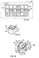
- Figure 10 shows a top view of an idealized embodiment of the invention.
- a thin metal sheet 100 (shown in phantom dashed lines) overlies and contacts upper contact surface 101.
- the contact surface area 102 of any segment 103 of the separator will be a small percentage of a planar area of the separator (the area encompassing all of the various segments 103), e.g. no more than 30% of the planar area, more usually less than 20% or 10% or even 5% and even lower than 1% of the planar area in connection with an embodiment.
- the contact surface is open, i.e. not continuous in an X-Y direction uppermost plane.
- FIG. 11 This can better be seen from Figure 11 where one unit 105 of Figure 10 is shown as an isolated unit 110.
- the contact surface area 111 (shown hatched) is open and, thus, a small percentage of the planar area 112 (shown cross-hatched) of that isolated unit 110, e.g. 10% or less of the planar area 112. This considerably decreases the contact surface area 111, i.e. by the percentage of the open area, and, consequently, the unwanted conduction heat transfer in the Z-direction.
- the units 105 of Figure 10 may have a variety of shapes which decrease the contact surface area, i.e. increase the open area, such as units 106, 107 and 108 of Figure 10, which variety of shapes is exemplified in Figure 12 where sides 120 have increased open area and, hence, decreased contact surface areas 121 (shown hatched), as opposed to the contact surface area 122 of side 123, which side has an open area and, hence, a contact surface area 122 identical to the contact surface area 111 of a side of a unit 110 in Figure 11.
- Such shapes of sides 120 provide a plurality of contact portions 125 which are generally spaced apart, with intervening open area, as shown in Figure 12, and with such shapes and spacing apart, the cumulative contact surface area with a thin metal sheet 128 (shown in dashed phantom lines) can easily be 10% or less of the planar area 112, shown in Figure 11.
- the open area need not extend entirely through the shape in the Z-direction, and may have a partition portion or a partial partition portion, for example, disposed along, for example, planar area 112.
- These shapes can take a wide variety of form, as exemplified in Figure 12, including but not limited to the shown "V" shape, "toothed” shape, "H” shape, and circular or oval shape, as well as many others.
- the contact portions 125 on both the upper and lower contact surfaces 121 and 129 should be connected by Z-direction connectors 130 which are capable of being substantially compressively loaded (e.g. columnar loading), so as to increase transverse rigidity and avoid crushing or damage or crimping of the insulators in the Z-direction, for the reasons briefly discussed above.
- This compressive loading is easily achieved by the shapes shown in Figure 12.
- the contact portions 125 be connected to at least one other contact portion 125 by X and/or Y-direction connectors 131, or the partition or partial partitions noted above, so as to, again, provide structural integrity of the separators, and more preferably where substantially all of the contact portions 125 are connected to adjacent contact portions by said X and Y-direction connectors, as shown in Figure 10.
- the X and/or Y-direction connectors do not substantially contact the thin metal sheet 128, as shown in Figure 12, as opposed to substantial contact thereof, as shown in Figure 10. This means that shapes, as exemplified in Figure 11, are most preferred.
- Figure 13 shows a cross-section of an insulator of the Sheridan, et al patents, and as can be seen, the Sheridan, et al patents attempt to reduce the Z-direction conduction heat transfer by replacing the separate and distinct woven separator of Rhudy with a plurality of embossments 136 extending from layers 138a through 138e of-the thin metal sheets, with the layers being offset with respect to each other such that at least some of the embossments are not aligned in the Z-direction.
- the embossments can also be in a non-uniform pattern or shape. While this arrangement limits conduction heat transfer in the Z-direction because of the limited contact portions 139 forming limited contact surface area on one end of the embossments, the other end of the embossments 140 have essentially no reduction in the contact portion, and, hence, contact surface area, which allows, essentially, unimpeded conduction heat transfer therethrough.
- the conduction heat transfer can be reduced by the corresponding number of embossments, but this, also correspondingly, reduces the Z-direction rigidity and resistance to damage, crimping, etc., as explained above.
- the shape of the embossments are not conducive to compressive, i.e.
- the separators are made from a knitted, metal wire, fabric, i.e. a non-woven, open material, as shown in Figure 3, which is commercially available and relatively inexpensive.
- the most preferred embodiment is where the separators are made from a twisted, open, expanded metal foil, as shown in Figures 5A and 5B, since such foils provide Z-direction integrity almost as good as the knitted fabric, but are much less expensive and provide lighter heat shields for automobiles, where cost and weight reduction are always important.
- the separators may be a combination of the knitted fabric and the twisted, expanded metal foil. For clarity purposes, the knitted fabric embodiment will be first discussed.
- the knitted fabric separator 2 is composed of interlocking loops 8 (also see Figure 3), in the usual manner of constructing a knitted fabric. While Figure 2 shows five thin metal sheets 3 through 7, and four separate and distinct knitted, metal wire, fabric separators 2, of course, the number of thin metal sheets and knitted fabric separators will depend upon the particular application of the insulator, and may be as little as only two thin metal sheets and one knitted fabric separator, or as many as fifteen to twenty-five thin metal sheets and fourteen to twenty-four knitted fabric separators.
- the peripheral edges of the insulator may be open, but, most preferably, especially when the insulator is in the form of a heat shield -for automobiles, in order to prevent egress of moisture or water, the peripheral edges are closed or sealed or at least partially closed or sealed.
- the peripheral edges may be closed in a number of different manners, and the particular manner of closing the peripheral edges is, not critical, but, optionally, the peripheral edges may be closed by a crimp and/or weld 9 or a clamp 10, as shown in Figure 2.
- a crimp and/or weld 9 or a clamp 10 as shown in Figure 2.
- the thickness of the thin metal sheets is not critical, but generally will range from 0.0127 to .762 mm (0.0005 to 0.030 inch), and more preferably from 0.0254 mm to .254 mm (0.001 inch to 0.010 inch). However, since it is important to have a high surface area to thickness of the thin metal sheets in order to maximize radiation heat transfer from the sheets, per unit weight of the sheets, it is preferable that the surface area to thickness ratio of the thin metal sheets be at least 1000:1., and more preferable at least 2000:1, and even more preferably at least 3000:1.
- the material of the thin metal sheets is not critical and may be, among others, steel, stainless steel, aluminum, copper, brass, bronze and tin.
- the thin metal sheets may be constructed with a base metal layer, e.g. a base metal of steel, aluminum, etc., and with a coating thereon, e.g. aluminum, copper, brass, bronze and tin.
- the coating is preferably an anti-corrosion coating, such as zinc, copper, silver or chromium.
- the distance that the sheets are spaced apart affects the heat transfer by both radiation and convection, and it is, accordingly, preferable that the sheets not be either too close together or too far apart.
- the insulator becomes bulky. It is, therefore, preferable that the sheets are spaced apart from 1.27 mm to 25.4 mm (0.050 inch to one inch), and more preferably 2.54 mm or 0.508 mm to 12.7 mm (0.100 inch or 0.020 inch to 0.500 inch).
- the sheets have a low thermal emissivity, especially an emissivity less than 0.1, and more preferably less than 0.05.
- the knitted, metal wire, fabric separator can be made of any metal which can be formed into a wire for knitting purposes, but, preferably, the wire of the knitted, metal wire, fabric separator is steel, stainless steel, aluminum, copper, brass, bronze and tin, similarly to the sheets, the metal wire may have a coating thereon, the same as described above in connection with the sheets, and, when corrosive environments are encountered, preferably the coating is an anti-corrosive coating, which anti-corrosive coating is the same as that described above in connection with the sheets.
- the wire may simply have an oxidized film thereon, such as the oxidation film of aluminum wire.
- the oxidation film forms a heat resistant film on the wire, which decreases heat transfer by conduction.
- Such an oxidation film may also be used on the surfaces of the thin metal sheets, if desired.
- the diameter of the wire can be from as little as 0.0127 mm (0.0005 inch) to much higher, such as 0.762 mm (0.030 inch), but more usually will be 0.0254 mm to 0.127 mm (0.001 inch to 0.005 inch).
- the knitted fabric has at least three knit loops per linear inch, and more preferably at least five knit loops per linear inch, and even more preferably at least ten knit loops per linear inch.
- the number of loops shown in that illustrative pattern is four loops per linear inch, as indicated by arrows 21.
- the loops of the knitted, metal wire, fabric separator, at the outermost end 25 thereof have arcs 26 with a radius no more than the distance 27 between the spaced-apart sheets, e.g. sheets 3 and 4.
- the arc shown in Figure 4 is, of course, considerably less than that distance 27.
- the radius of that arc should be no more than 6.35 mm (0.25 inch), and far more preferably no more than 2.54 mm (0.1 inch).
- the radius of those arcs can be quite small, however, e.g. 0.254 mm (0.01 inch) or less.
- any conventional knit configuration is useful, but a very convenient pattern of knit is the over-hand knit, as shown in Figure 3, and this is a convenient form of the knit for purposes of the present invention.
- other knit configurations may be used, as desired.
- the knitted fabric separator 2 may be substantially co-extensive with at least one of the sheets, e.g. sheet 30 of Figure 6, but it may be less than co-extensive as shown on sheet 31 of Figure 6, which shows the knitted, metal wire, fabric separator in strips.
- disc 33 of the knitted, metal wire, fabric separator may be used, e.g. discs of 0.5 to 4 inches or more.
- the knitted, metal wire, fabric separator may be in strips of particular configurations, such as strips 34 on sheet 35 of Figure 6.
- the knitted fabric separator need not be planar, such as shown by knitted fabric separator 60, in Figure 7, but may have a non-planar configuration, such as the crimped configuration of knitted fabric separator 61, as shown in Figure 7.
- peripheral edges of the sheets may be in contact with each other, as shown at the crimped edge 9 of Figure 2.
- the peripheral edges of the sheets may be in contact with the knitted fabric, again as shown in Figure 2 at crimped peripheral edge 9.
- at least some of the sheets, e.g. sheet 6 may terminate before reaching the peripheral edge 70 and some of the knitted fabric separators may also terminate prior to reaching the peripheral edge 70, as shown by the edge 71 of knitted fabric separator 2 in Figure 2. While this could appear to provide a decreased X-Y stability of the, insulator in view of the separators being separate and distinct from the sheets, e.g. not attached or formed therefrom, surprisingly, this is not the case.
- the contact portions, while each being small, are large in number, and the resulting friction between the separate and distinct separators and the sheets is great, giving good X-Y stability.
- All of the sheets used in the insulator need not be spaced apart the same distance as other sheets, and at least two adjacent sheets may be spaced apart a different distance from two other adjacent sheets, as shown by the distances 81 and 82 of Figure 2.
- the heat shield 1 may be in the form of a complex configured heat shield, as shown in Figure 8, e.g. where the heat source is part of an exhaust system, generally 92, of an automobile, again as shown in Figure 8.
- the Z-direction compressive strength of the knitted fabric is sufficient to prevent substantial Z-direction compression of the insulator upon impact thereof by usual road hazards. This must be achieved, while at the same time limiting heat transfer through the insulator in the Z-direction (transverse direction), by either conduction or convection heat transfer, as also explained above.
- the ability of the present knitted fabric to achieve these results can best be understood by reference to Figure 4.
- a loop 25 of knitted fabric separator 2 will, generally, upstand from the planar area of the knitted fabric and contact a thin metal sheet 3 at a tangent, or contact portion 27. It is only at that tangent, or contact portion 27 that heat can be transferred by conduction from sheet 3 through the tangent, or contact portion 27, wire loop 25, wire loop 28 and the tangent, or contact portion 29 to the next under thin metal sheet 4. Thus, the limiting factor in such heat conduction is the tangent, or contact portions 27 and 29. If the area of those contact portions is kept small by a small arc 26 of loop 25, the area for heat conduction will be decreased.
- the use of the knitted fabric of the present invention avoids the difficulties of a woven material, according to the Rhudy patent or the embossments of the Sheridan, et al patents.
- the knitted fabric is a very improved fabric for limiting conduction and convection heat transfer between adjacent thin metal sheets, which transfer is to be avoided to the extent possible, but, in addition thereto, the knitted fabric provides very substantial Z-direction strength, as briefly noted above.
- the knitted, metal wire, fabric separator 2 is interdisposed between adjacent thin metal sheets 3, 4, 5, 6 and 7.
- the loops of the knitted fabric separator have small tangent, or contact portions (27 and 29 in Figure 4), there are a large number of such loops contacting adjacent thin metal sheets.
- This could be analogized to a multitude of small points of support, spacing apart adjacent sheets, but, cumulative, provide very substantial support for maintaining that spaced-apart relationship, even when a substantial stress is applied to the insulator in the Z-direction. That stress could, among others, be a result of a road hazard for an automobile (e.g.
- the thin metal sheets are so supported by the knitted fabric that the sheets will not be dented or otherwise unduly stressed, as opposed to the embossment arrangement of the Sheridan, et al patents.
- the knitted fabric separator since the knitted fabric separator has substantial Z-direction columnar (compressive) loading capabilities, this allows the insulator to be configured into complex shapes without the insulator substantially buckling or crinkling or indenting, which would, again, increase the above-noted heat transfer.
- a knit inherently, has essentially full degrees of freedom in the X and Y-directions (planar directions) thereof, the knit can stretch or compact in both of these directions, since it is separate and distinct from the sheets (not attached), and this very greatly facilitates the forming of the insulator into very complex shapes without the insulator crinkling, buckling or indenting.
- the use of the knitted fabric separator also provides very important advantages in construction of the insulator. As opposed to the Sheridan, et al patents, where embossments are required in the thin metal sheets, no such embossments are required with the present invention, and the complex and complicated machinery for forming the embossments of the Sheridan, et al patents may be totally eliminated. Likewise, the embossed sheets of the Sheridan!
- the knitted fabric separator may be simply laid on the thin metal sheets without any particular care in such laying, and the insulator formed by closing the peripheral edges (totally or partially) by usual manufacturing methods, e.g. crimping or welding or a combination thereof. Further, no special care is required in forming the insulator into complex configurations, since, with the present knitted fabric, those complex configurations can be achieved without fear of causing undue Z-direction stress and the attendant difficulties, e.g. buckling, crinkling and the like.
- the knitted, metal wire, fabric separator is commercially available, and the thin metal sheets are, of course, readily commercially available. Accordingly, the process for producing the present insulators is quite simple. All that is required is that of laying a thin metal sheet on a support, overlaying that thin metal sheet with the knitted fabric separator, and repeating that process until the desired number of thin metal sheets and knitted fabric separator layers are provided. That assembly is then cut to size and placed in a conventional crimper or the like to crimp peripheral edges (the entire peripheral edge or a part thereof), and, if desired, that edge may also be welded, e.g. spot welded with a conventional spot welding machine, for added security of the insulator.
- the insulator requires special contours, those contours can be achieved simply by placing the so-formed insulator into a die/press for forming the insulator in the complex configuration. Since the thin metal sheets are still pliable and the knit, as explained above, has degrees of freedom in the X and Y-directions, and substantial freedom in the Z-direction, that die/press operation need not be carried out with any heating and may a cold forming operation. If desired, the top and bottom thin metal sheets may have a pattern of light or heavy score lines 11 (see Figures 1A and 1 B) of conventional nature to facilitate such forming.
- the knitted fabric separator embodiment is equally applicable to the twisted, expanded foil embodiment of the separator and will not be repeated for sake of conciseness.
- the twisted, expanded foil embodiment of the separator is shown in Figures 5A and 5B. While the expanded foil embodiment of the separator does not have as good Z-direction rigidity as the knitted fabric embodiment and, in that sense, is not a preferred embodiment for general applications of the insulator, the expanded foil embodiment does have advantages for the specialized application of an automobile heat shield, e.g. near an exhaust system thereof; and, in that sense, is the preferred embodiment of the separator for such application.
- the expanded foil is less expensive and lighter in weight than the knitted fabric, and both of these are important for automobile application of the insulator.
- the peripheral edges (see Figures 1A and 2) must be sufficiently sealed near compressed portions 20 to substantially prevent egress of moisture, as noted above.
- a conventional pressing operation i.e. a conventional crimping operation
- some welding e.g. spot welding, or other sealing means, e.g. clamps, may be required, and this increases the cost, and possibly the weight, of a so-produced insulator, both of which are undesired for automobile use.
- the expanded foil embodiment is easy to compress at its edges with conventional pressing operations since it is collapsible in the Z-direction to essentially a planar configuration, as opposed to a knitted fabric.
- the foil may be sealed in such a conventional pressing operation, e.g. a conventional "toy" crimping operation, and, in this sense, is superior in function to the knitted fabric for an automobile exhaust system heat shield, and, thus, a preferred embodiment therefor.
- the twisted expanded foil separator, generally, 45 is a relatively new manufacture and is made by simultaneously cutting a thin metal sheet and stretching the metal sheet while bending at about a 180° angle, such that all of the X, Y and Z-dimensions are greater than the original, e.g. 2 to 50 times in the X and Y-directions to 200 times or more in the Z-direction.
- the vertically disposed portions extend further from a central plane of the expanded foil than do the twisted portions.
- This is idealized in Figure 5A where there are a plurality of generally vertically disposed portions 46 connected by twisted portions 47. All parts of the twisted portions 47 lie closer to a central plane 48 of the expanded foil than do all parts of the vertically disposed portions 46, and, therefore, the generally vertical portions 46 have an upper surface 49 and a lower surface 50 which extend, respectively, further from central plane 48 than do the twisted portions 47.
- a twisted, expanded, metal foil provides contact portions, as indicated by arrows 52 (the upper and lower parts of vertical portions 50) having contact surfaces the same as described above in connection with the generalized embodiments of Figures 10, 11 and 12.
- the open structure and, hence, cumulative contact surface area of the contact portions 52 is small compared with the planar area 48, as required above in connection with the generalized embodiments of Figures 10, 11 and 12 and, indeed, considerably less than 30% of that planar area, i.e. less than 1%. In the embodiment of the following example, the surface area is only 0.3%.
- the contact portions 52 are spaced apart and, thus, provide the same spaced-apart contact surfaces, as also required by the generalized embodiments.
- the contact portions on the upper and lower surfaces are spaced apart by a substantial Z-direction dimension and are connected by Z-direction connectors, i.e. the main body of the vertical portions 50, and are capable of substantial compressive loading.
- each contact portion (vertical portion 50) is connected to another contact portion by X and/or Y-connectors, i.e. twisted portions 47 which do not substantially contact a thin metal sheet when used as a separator.
- the twisted, expanded foil meets all the requirements as explained above in connection with the generalized embodiments, but is also light in weight, inexpensive, and sealable at the peripheral edges, which makes it ideal for use in providing the automobile exhaust heat shield.
- the present open separators with substantial Z-direction dimension can function well in the present insulators.
- the separators should have a Z-direction dimension with a ratio of at least 0.10, preferably 0.15 and more preferably 0.20, and up to 0.5 or more of a unit planar area.
- the Z-direction dimension should be at least 0.1 centimeter, i.e. a ratio of 0.1.
- the Z-direction increase compared with the non-expanded metal foil, is very great, e.g. the Z-direction expansion can easily be 190 times or more, e.g. from a non-expanded metal sheet of 0.0508 mm (0.002 inch) to an expanded sheet of 9.525 mm (0.375 inch).
- An automobile exhaust system heat shield was produced by laying a bottom thin metal sheet of aluminum foil of 0.0508 mm (0.002 inch) thickness.
- the aluminum was a bright finish grade of 1145 aluminum alloy with a 1/4 hard temper and a lightly scored 19.05 mm by 6.35 mm (.75 inch by .25 inch) diamond pattern was on the surface thereof.
- Twisted expanded aluminum foil 0.0508 mm (0.002 inch) original thickness and about 9.525 mm (3/8 inch) final thickness, with a Z-direction ratio of about 0.15 and a density of 105.94 grams per cubic meter (3 grams per cubic foot)) was laid on the bottom sheet. Additional layers of sheet and expanded foil were also laid and lastly a top thin metal sheet was placed thereon, the top metal sheet being the same as the bottom sheet, except that it had a thickness of 0.1016 mm (0.004 inch).
- the so assembled layers were simultaneously cut with steel rule trim dies to approximately desired sizes.
- the outer one inch edge of the die cut assembly was flattened for crimping and folding purposes and the assembly was crimped in a "Toy Curl" crimper such that 6.35 to 12.7 mm (1/4 to 1/2 inch) of the peripheral edge was folded under toward the bottom sheet by using 3 HIT punch dies (Generalizer Tool & Die Co., Greensboro, Ohio) to seal the peripheral edges.
- test shields were made having various numbers of such layers.
- the test shields were serially placed in a heatbox with a 211,011.2 Kilojoules/hr (200,000 BTU/hr).
- torch generator heating a 57.15 mm (2.25 inch) pipe (to simulate an automobile exhaust pipe) and a simulated automobile floorpan (20 gauge sheet steel) was placed about one inch from the pipe.
- a fan simulated air flow over the test assembly (simulates a moving automobile).
- Each test sample was placed between the pipe and floorpan, and the pipe was heated for 30 minutes at 537.8°C ⁇ 6.67°C (1,000°F ⁇ 20°F) and with a wind speed (by the fan) of 60.96 meters/min (200 feet/min).
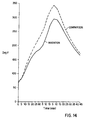
- Figure 14 shows the results of the present assembly having 10 layers of thin metal sheets and 9 layers of expanded foil labelled "Invention” and compared with a 10-layered embodiment of the Sheridan, et al patents, labelled "Comparison”.
- the maximum floorpan temperature of the Invention assembly was about 143.3°C (290°F)
- the maximum floorpan temperature of the Comparison assembly was about 171.1 °C (340°F)
- the Invention assembly decreases heat transfer by about 32%.
- Figure 15 shows the outer sheet temperature of a similar test, except that the "soak" period was eliminated and the heat was continuous at 565.6°C ⁇ 6.67°C (1,050°F ⁇ 20°F) for an assembly of 6 layers of both the Invention assembly and the Comparison assembly for samples of 0.3048 meters by 0.3048 meters (12 inches by 12 inches). It can be seen that the Invention assembly reduced the outer sheet temperatures by an average of 14%.
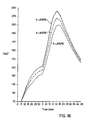
- Figure 16 shows floorpan temperatures of a similar test, but with 6 layers, 5 layers and 4 layers of the Invention assembly. It will be seen that the temperature profiles are similar, but the floorpan temperature drops 7.78°C (18°F) on average for each additional layer.
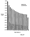
- the initial thickness of the Invention sample (6 layers) was 10.4 mm (0.410 inch), while the thickness of the comparison sample (6 layers) was 7.87 mm (0.310 inch), which is a result of the present greater Z-direction dimension of the present expanded foil separators.
- the Invention sample compressed to 9.6 mm (0.378 inch) (7.8%), while, with that same weight, the Comparison sample compressed to 5.97 mm (0.235 inch) (24%). Both samples, thereafter, gradually compressed through a loading of a total of 1200 grams (42 ounces). This portion of the test simulates road hazards, e.g. stones thrown into the heat shield of an automobile at different speeds or weights. It can be seen, therefore, that the Invention sample is quite superior to the Comparison sample in this regard.
- the invention provides a 32% decrease in heat transfer, a decrease in outer sheet temperature of 14%, and a quite significant increase in Z-direction compressive strength. Results of this nature provide a substantially improved metal heat insulator.
Landscapes
- Engineering & Computer Science (AREA)
- Mechanical Engineering (AREA)
- General Engineering & Computer Science (AREA)
- Laminated Bodies (AREA)
- Thermal Insulation (AREA)
- Inorganic Insulating Materials (AREA)
- Insulated Conductors (AREA)
- Exhaust Gas After Treatment (AREA)
- Exhaust Silencers (AREA)
Abstract
Description
- The present invention relates to metal heat insulators, of a known type, having at least two generally elongated, planar, thin metal sheets disposed generally one above the other in a spaced-apart relationship with a metal separator therebetween contacting both of the sheets for maintaining that spaced-apart relationship. More particularly, the present invention relates to an improvement in the separator of such metal heat insulators.
- Heat insulators take many forms in the art, including insulators formed of woven and non-woven fibers of natural and synthetic materials, e.g. plastics, glass fibers, mineral fibers and ceramic fibers. These fiber insulators are specially designed for specific purposes, bearing in mind the environment in which these insulators must operate. However, there is a particular application of heat insulators where such usual insulators are unacceptable, i.e. in very high temperature environments and where those environments may include high moisture conditions and/or corrosive conditions. In these environments, the usual fiber insulators are ineffective, since the melting temperature or softening temperature of those fibers is less than the temperature at which the insulator must operate. In addition, when the insulators operate in high moisture conditions, the usual fiber insulators absorb moisture and that absorbed moisture very substantially reduces the insulating value of such insulators. Further, those environments which include both high temperature and moisture, often also include corrosive conditions, and such corrosive conditions can easily degradate conventional fiber insulators.
- For these very specialized environments, it has been known in the art that metal heat insulators are the best choice. These metal heat insulators, generally, have at least two generally elongated, planar, thin metal sheets disposed generally one above the other in a spaced-apart relationship, with a metal separator therebetween contacting both of the thin metal sheets for maintaining that spaced-apart relationship. Since these insulators are made entirely of metal, they can withstand the high temperatures and specialized environments. In addition, the thin metal sheets can be sealed at peripheral edges thereof, such as to make the insulator, essentially, watertight, and thus prevent the egress of moisture into the insulator. Also, in view of the very high temperatures of the environments, any moisture which does egress into the insulator is vaporized and, generally, expelled. Further, in corrosive conditions, the metal of the insulator, including both the thin metal sheets and the separator, can be made of an anti-corrosive metal or, alternatively, have an anti-corrosive coating or finish thereon, or parts thereof.
- Probably the earliest successful example of such a metal heat insulator is disclosed in U. S. Patent 3,212,864 to Rhudy, issued on October 19, 1965. As disclosed in that patent, the metal heat insulators thereof are useful for insulating pipes or tubes carrying very hot liquids, such as liquid sodium. The insulator is made of a plurality of thin metal sheets having reflective surfaces of low thermal emissivity and a separator formed from a woven metal cloth, screen or mesh is disposed between adjacent thin metal sheets to maintain the spacing therebetween.
- A more recent example of such insulators is shown in U. S. Patents 5,011,743 and 5,111,577 to Sheridan, et al, which patents have a common assignee. These patents, very similarly to the Rhudy arrangement, use a plurality of spaced-apart thin metal sheets, disposed one above the other, but the thin metal sheets of those patents are spaced apart by a plurality of embossments extending from at least one of adjacent thin metal sheets, as opposed to the separate separator of the Rhudy patent. Thus, the embossments of the sheets maintain the spacing of the sheets, and no separate independent separator, such as that shown in the Rhudy patent, is required. The insulators of the Sheridan, et al patents are adapted for use in insulating high temperature sources from temperature sensitive elements relatively adjacent thereto, and such insulators have been used, for example, in insulating high temperature exhaust components of an automobile from other temperature sensitive parts of the automobile, e.g. the floorpan.
- Very basically, in insulators of the nature described by the Rhudy patent and the Sheridan, et al patents, insulation is achieved by the spaced-apart thin metal sheets, such as thin aluminum sheets. Heat radiating from a heat source, e.g. an exhaust component, toward a first thin metal sheet of an insulator is, in part, absorbed by that first thin metal sheet. By conduction, that absorbed heat is spread across the length and width of that first sheet for dissipation by radiation, e.g. to a cooler part of an automobile under carriage, and by convection to air flowing over the insulator. Also, heat is radiated from that first sheet to a next underneath second sheet, but conduction between those two sheets is largely avoided, due to the spaced-apart configuration of those sheets, since the air gap between the two sheets significantly impedes heat transfer by conduction. This same insulating operation is continued to a next under sheet, etc., until a last underneath sheet again functions in the manner described above in connection with the first sheet.
- Thus, when heat is absorbed by the first sheet, part of that heat is dissipated by radiation to cooler parts of the undercarriage of the automobile, and part of that heat is radiated to the next under sheet. That heat is again conductively transferred laterally in the second sheet, the same as the first sheet, and again radiates to cooler parts of, the automobile. As this insulating function continues to the last underneath sheet, radiation and convection heat transfer to air flow over that last underneath sheet dissipates the heat and keeps that last underneath sheet relatively cool. In turn, an automobile component adjacent to the last underneath sheet is kept relatively cool, e. g. a floorpan of an automobile. The insulators, therefore, depend on maximum heat radiation from the insulator and minimum conductive heat transfer through the insulator.
- As can, therefore, be appreciated, a critical element of such metal insulators is the means of spacing apart the thin metal sheets. At every point of contact between the separator and an adjacent thin metal sheet, unwanted conduction heat transfer through the insulator will occur. In addition, the separator will, at least in part, decrease movement of convection currents between adjacent thin metal sheets, and such decreased movement will decrease unwanted heat transfer by convection through the insulator. Also, the shape, size and configuration of the separator substantially affects the ability to form or configure the insulator into more complex shapes, such as to accommodate, for example, the underbody of an automobile, while not collapsing the insulator in the transverse direction, i.e. the Z-direction.
- As noted above, the Rhudy patent suggests woven cloth, screen or mesh as the separator, and while each of these will provide substantial rigidity to the insulator in the Z-direction, i.e. transverse to the planar direction of the sheets, for conforming the insulator to more complex shapes as promised by Rhudy, each of these forms also makes substantial metal-to-metal contact with adjacent thin metal sheets, and, accordingly, the unwanted conductive heat transfer through the insulator is substantial. In addition, each of these forms of separators allows substantial heat transfer by convection.
- On the other hand, the Sheridan, et al patents disclose embossments of at least one of adjacent thin metal sheets, which serve to maintain the spaced-apart relationship. These embossments limit the metal-to-metal contact between adjacent sheets and, therefore, limit conduction heat transfer through the insulator, as opposed to the greater metal-to-metal contact of the separators of the Rhudy patent. Therefore, there is a decrease in the amount of conduction heat transferred through the insulator. However, those embossments will allow substantial air currents between adjacent sheets and, therefore, heat transfer through the insulator by convection is significant.
- While the Sheridan, et al patents provide some latitude for the configuration of those embossments, the embossments are, something in the configuration of an egg crate design, such that conduction heat transfer between adjacent sheets is limited to that conduction occurring between the metal-to-metal contact of the embossments and an adjacent sheet.
- However, this arrangement leads to three serious difficulties. Firstly, the embossments of the Sheridan, et al patents are fairly large, relative to the thickness of the sheets, and, in toto, the embossments still provide substantial area of metal-to-metal contact between the embossments and an adjacent thin metal sheet, through which substantial conduction heat transfer takes place.
- Secondly, those relatively large embossments allow significant movement of air currents between adjacent thin metal sheets, and, hence, convection heat transfer between adjacent thin metal sheets is quite significant.
- Thirdly, since the embossments are formed from relatively thin metal sheets, e.g. aluminum foil, those relatively thin embossments provide very little compressive strength to the insulator in the Z-direction, i.e. the transverse direction to the planar direction of the sheets. When such an insulator is deployed as a heat shield under the body of an automobile, e.g. between a hot source of the exhaust system and the floorpan, the heat shield can be seriously dented in that transverse direction by ordinary road hazards, such as thrown stones, or can be damaged by misadventures of mechanics working in the area of the heat shield. Also, since the compressive strength, or rigidity, of the insulator in the transverse direction is relatively low, the insulator may buckle when being formed into necessary contours, e.g. for deployment as a heat shield under an automobile body, and especially when, complex contours are required. Of course, each dented or buckled area constitutes an area for substantially increased unwanted conduction heat transfer. This causes serious reliability problems for the insulators of the Sheridan, et al patents, especially when used as a heat shield under an automobile, as briefly noted above.
- It would, therefore, be of decided advantage to the art to provide such insulator, e. g. as heat shields, of the above nature, but which heat shields have decreased transverse conduction and convection heat transfer and, at the same time, provides substantial transverse direction compressive strength, or rigidity, such that the heat shields can withstand ordinary road hazards and can be conformed into complex contours without buckling or other deformation.
- The present invention is based on several primary discoveries and several subsidiary discoveries.
- As a first discovery, it was found that, if the separator between adjacent thin metal sheets is separate and distinct, i.e. not permanently attached to or part of the sheets as in the Sheridan, et al patents, and made of certain non-woven, substantially open, metal materials, as opposed to the woven materials of the Rhudy patent, and has a substantial Z-direction dimension, that material will provide high transverse direction compressive strengths to the insulator, while at the same time very significantly reduces conductive heat transfer through the insulator.
- As a second primary discovery, it was found that these certain non-woven, substantially open, metal materials have substantial degrees of freedom in the X and Y-directions, as opposed to the woven .materials of the Rhudy patent. Thus, the non-woven material can easily bend, expand or contract in all planar directions and to a significant extent in the Z-direction. This allows formation of complex shapes and contours of a heat shield without buckling or other deformation.
- As a subsidiary discovery in the foregoing regard, it was found that those certain non-woven materials have substantial Z-direction columnar strengths, i.e. compressive strengths, or rigidity, and the bending for producing complex shapes will not cause any substantial change in the Z-direction thickness of the insulator. Thus, the insulator will, essentially, stay intact in the Z-direction dimension, even with significant bending for contouring or configuring the insulator to a necessary shape for use as a heat shield fitted underneath an automobile body.
- As another primary discovery, it was found that, when those certain non-woven materials have a substantial Z-direction dimension, only a small portion of the surfaces of the materials will actually contact an adjacent thin metal sheet. In view of this very small contact area, cumulative, the contact area of the materials with adjacent sheets is quite small, and, therefore, conduction heat, transfer through the insulator is not substantially compromised, as opposed to the woven materials of the Rhudy patent.
- As another primary discovery, it was found that, with the substantial Z-direction dimension of the non-woven material, as opposed to the more flat configuration of the woven materials of the Rhudy patent, significant transverse direction openings occur, and those openings substantially decrease movement of, air currents between adjacent thin metal sheets, and, accordingly, heat transfer by convection is decreased, e.g. as opposed to the Sheridan, et al patents.
- As a further subsidiary discovery, it was found that certain of the non-woven materials have substantial degrees of freedom in all directions, i.e. in the X, Y and Z-directions, and, therefore, substantial flexing of the insulator, e.g. as that which can be occasioned in use as a heat shield under automobile bodies, will not substantially deform the heat shield, as opposed to the heat shield of the Sheridan, et al patents.
- The certain non-woven metal materials of the present invention, used as the separator, have in common a substantial Z-direction dimension and a decreased contact surface area on the upper and lower contact surfaces thereof, i.e. the surfaces which contact an adjacent thin metal sheet. More specifically, these certain non-woven metal materials have contact surfaces with contact surface areas less than about 30% of a planar area of the separator parallel to the X and Y-dimensions of the separator. Stated another way, in a separator having X and Y-dimensions of A and B, the surface area of a plane parallel to the X and Y dimensions equals A x B, and the present non-woven metal separators must have an upper surface (which contacts one adjacent thin metal sheet) and a lower surface (which contacts the next adjacent thin metal sheet) where total area of contact between the upper and lower surfaces is less than 300 of A × B.
- Thus, very briefly stated, the present invention relates to an improvement in a generally elongated, thin, metal sheet heat insulator having at least two generally elongated, thin, metal sheets disposed generally one above the other in a spaced apart relationship and a metal separator therebetween contacting both said sheets for maintaining the spaced apart relationship, the improvement comprising:
- non-woven, substantially open, metal separator which is not permanently attached to or part of the sheets and has a substantial Z-direction dimension and has substantially parallel upper and lower contact surfaces spaced apart in a Z-direction ; said separator being in the form of a twisted expanded ;metal foil having spaced apart substantially vertically disposed portions and cut twisted portions connecting the vertically disposed portions and the vertically disposed portions extending further from a central plane of the foil than the twisted portions such that the twisted portions do not substantially contact the thin metal sheets and the upper contact surface and a lower contact surface formed by the vertically disposed portions have contact surface areas of less than 30% of a planar area of the separator parallel to X and Y-dimensions of the separator.
-
- Figure 1A is a partly elevated isometric view of a contoured insulator according to the present invention and suitable for use as an automobile heat shield, and Figure 1B is a top view thereof;
- Figure 2 is a cross-sectional view of Figure 1 taken along lines I-II;
- Figure 3 is a representative pattern of a typical knitted separator useful with the present invention;
- Figure 4 is a highly idealized diagrammatic illustration of contact between the present knitted separator and adjacent thin metal sheets;
- Figure 5A is an isometric representative pattern of a typical twisted expanded foil separator useful with the present invention, and Figure 5B is a plan view thereof;
- Figure 6 is an illustration of various arrangements of the separator on one of the thin metal sheets;
- Figure 7 is an idealized cross-section of two thin metal sheets with multiple layers of separators;
- Figure 8 is a diagrammatic illustration of the placement of the present insulator, in the form of a heat shield, underneath an automobile body and adjacent to an exhaust component;
- Figure 9 is a diagrammatic illustration of a typical woven separator of the prior art;
- Figures 10, 11 and 12 are diagrammatic illustrations of differences between the prior art separator of Figure 9 and the present separators;
- Figure 13 is an illustration of other prior art and, in comparison with Figures 10, 11 and 12, illustrates differences between that prior art of Figure 13 and the present invention; and
- Figures 14, 15, 16 and 17 graphically present the data reported in the working example.
- As can be seen in Figures 1A and 1B, the present heat insulator, e.g. in the form of an automobile heat shield, generally, 1 (see Figure 1B) can be in a very complex configuration (see Figure 1A) and still enjoy the advantages briefly described above. As shown in Figure 2,
separators 2 space apartthin metal sheets peripheral edges 9 are usually sealed, e.g. may be clamped together byclamp 10. Thus, as so far described, Figures 1 and 2 illustrate the usual arrangement of prior art insulators. - Figures 1 through 5 show preferred embodiments of the present invention. However, for a more general understanding of the invention and differences between the invention and the prior art, Figures 9 through 13 are more instructive. Hence, those Figures will be first discussed in detail.
- Figure 9 shows a cross-section of a Rhudy patent insulator having
thin metal sheets separator 93 consists of wovenwarp threads 94 and weft threads 95 (only one being shown). The inherent curvature of theweft threads 95, going under and over thewarp threads 94, results in upper andlower contact portions thin metal sheets contact surfaces 97a and 97b. These contact surfaces, generally, lie incontact planes 98a and 98b, which contact planes are substantially parallel to each other and substantially parallel to a planar area 99 (the plane being into the paper of the drawings). Of course" a cross-section of the Rhudy insulator showing a cross-section through theweft threads 93, as opposed to the cross-section of Figure 9 through thewarp threads 94, would be identical to Figure 9. - As can therefor be seen from Figure 9, both the upper contact surface 97a and the
lower contact surface 97b, for a typical woven separator, form a total contact surface area of 50% of theplanar area 99 of the separator parallel to the X and Y-dimensions thereof. In practical terms, this means that the contact surface areas ofcontact planes 98a and 98b are only 50% less than that of a theoretical solid cross-section separator and, thus, 50% of the conduction heat transfer through such a theoretical separator in the Z-direction will take place through the contact surface areas ofcontact planes 98a and 98b. This is simply too much contact surface area and very substantially reduces the efficiency and heat resistance of the insulator. - In addition, the Z-direction dimension of the woven separator is not substantial, as defined more specifically below, and this is inherent in a woven fabric because of the necessary lie of the warp and weft threads. Thus, the sheets must either lie close to one another or multiple layers of the woven separators must be used between sheets, which significantly increases cost and weight of the insulator.
- Figure 10 shows a top view of an idealized embodiment of the invention. In this figure, a thin metal sheet 100 (shown in phantom dashed lines) overlies and contacts
upper contact surface 101. It can be seen that thecontact surface area 102 of anysegment 103 of the separator will be a small percentage of a planar area of the separator (the area encompassing all of the various segments 103), e.g. no more than 30% of the planar area, more usually less than 20% or 10% or even 5% and even lower than 1% of the planar area in connection with an embodiment. This is because the contact surface is open, i.e. not continuous in an X-Y direction uppermost plane. By so decreasing the contact surface area, unwanted conduction heat transfer through the Z-direction of the present insulator is correspondingly decreased. - This can better be seen from Figure 11 where one
unit 105 of Figure 10 is shown as anisolated unit 110. As can be seen from Figure 11, the contact surface area 111 (shown hatched) is open and, thus, a small percentage of the planar area 112 (shown cross-hatched) of thatisolated unit 110, e.g. 10% or less of the planar area 112. This considerably decreases thecontact surface area 111, i.e. by the percentage of the open area, and, consequently, the unwanted conduction heat transfer in the Z-direction. - To even further reduce the
contact surface area 111, theunits 105 of Figure 10 may have a variety of shapes which decrease the contact surface area, i.e. increase the open area, such asunits sides 120 have increased open area and, hence, decreased contact surface areas 121 (shown hatched), as opposed to thecontact surface area 122 ofside 123, which side has an open area and, hence, acontact surface area 122 identical to thecontact surface area 111 of a side of aunit 110 in Figure 11. - Such shapes of
sides 120 provide a plurality ofcontact portions 125 which are generally spaced apart, with intervening open area, as shown in Figure 12, and with such shapes and spacing apart, the cumulative contact surface area with a thin metal sheet 128 (shown in dashed phantom lines) can easily be 10% or less of the planar area 112, shown in Figure 11. The open area need not extend entirely through the shape in the Z-direction, and may have a partition portion or a partial partition portion, for example, disposed along, for example, planar area 112. These shapes can take a wide variety of form, as exemplified in Figure 12, including but not limited to the shown "V" shape, "toothed" shape, "H" shape, and circular or oval shape, as well as many others. - However, whatever shape is adopted, for purposes of structural integrity of the separator the
contact portions 125 on both the upper and lower contact surfaces 121 and 129 should be connected by Z-direction connectors 130 which are capable of being substantially compressively loaded (e.g. columnar loading), so as to increase transverse rigidity and avoid crushing or damage or crimping of the insulators in the Z-direction, for the reasons briefly discussed above. This compressive loading is easily achieved by the shapes shown in Figure 12. - It is also most preferred that at least some of the
contact portions 125 be connected to at least oneother contact portion 125 by X and/or Y-direction connectors 131, or the partition or partial partitions noted above, so as to, again, provide structural integrity of the separators, and more preferably where substantially all of thecontact portions 125 are connected to adjacent contact portions by said X and Y-direction connectors, as shown in Figure 10. Of course, to limit transverse conduction heat transfer through the X and/or Y-direction connectors, it is even more preferable that the X and/or Y-direction connectors do not substantially contact thethin metal sheet 128, as shown in Figure 12, as opposed to substantial contact thereof, as shown in Figure 10. This means that shapes, as exemplified in Figure 11, are most preferred. - The foregoing makes clear the present invention and how, in certain respects, it departs from the prior art shown in Figure 9, i.e. the woven separators of the Rhudy patent. Figure 13 shows a cross-section of an insulator of the Sheridan, et al patents, and as can be seen, the Sheridan, et al patents attempt to reduce the Z-direction conduction heat transfer by replacing the separate and distinct woven separator of Rhudy with a plurality of
embossments 136 extending fromlayers 138a through 138e of-the thin metal sheets, with the layers being offset with respect to each other such that at least some of the embossments are not aligned in the Z-direction. The embossments can also be in a non-uniform pattern or shape. While this arrangement limits conduction heat transfer in the Z-direction because of thelimited contact portions 139 forming limited contact surface area on one end of the embossments, the other end of theembossments 140 have essentially no reduction in the contact portion, and, hence, contact surface area, which allows, essentially, unimpeded conduction heat transfer therethrough. The conduction heat transfer can be reduced by the corresponding number of embossments, but this, also correspondingly, reduces the Z-direction rigidity and resistance to damage, crimping, etc., as explained above. In addition, the shape of the embossments are not conducive to compressive, i.e. columnar, loading and the Z-direction rigidity is inherently much, less than that of the Rhudy patent arrangement, which is a serious disadvantage, as explained above. All of the foregoing combine to result in a less than desirable insulator, all in terms of conduction heat transfer, ultimate "skin" temperature (the temperature of an outside thin metal sheet) and resistance to damage, as clearly shown by the data of the below example. - Thus, it can be seen that the present invention, as explained in connection with the generalized embodiments of Figures 10, 11 and 12, not only significantly reduce the Z-direction unwanted conduction heat transfer, as opposed to the Rhudy patent and Sheridan, et al patents arrangements, but also provide Z-direction rigidity similar to the arrangement of the Rhudy patent, and very much better than the Sheridan, et al patents, as the below example shows, which is a very substantial improvement in the art.
- It will also be understood that, while the present generalized arrangements of Figures 10, 11 and 12 are quite improved arrangements, as noted above, those arrangements are also quite expensive to manufacture and, thus, would not be suitable for low cost insulators, such as required by automobile manufacturers. However, it has been found that the above-discussed properties of those generalized arrangements can be closely approximated with separators made of commercially available, low cost materials, and Figures 1 through 7 show those embodiments which are preferred because, only, of the low cost thereof.
- Thus, turning back to Figures 1 through 7, in a preferred embodiment, the separators are made from a knitted, metal wire, fabric, i.e. a non-woven, open material, as shown in Figure 3, which is commercially available and relatively inexpensive. The most preferred embodiment is where the separators are made from a twisted, open, expanded metal foil, as shown in Figures 5A and 5B, since such foils provide Z-direction integrity almost as good as the knitted fabric, but are much less expensive and provide lighter heat shields for automobiles, where cost and weight reduction are always important. Alternatively, the separators may be a combination of the knitted fabric and the twisted, expanded metal foil. For clarity purposes, the knitted fabric embodiment will be first discussed.
- As can be seen from Figure 2, the
knitted fabric separator 2 is composed of interlocking loops 8 (also see Figure 3), in the usual manner of constructing a knitted fabric. While Figure 2 shows fivethin metal sheets 3 through 7, and four separate and distinct knitted, metal wire,fabric separators 2, of course, the number of thin metal sheets and knitted fabric separators will depend upon the particular application of the insulator, and may be as little as only two thin metal sheets and one knitted fabric separator, or as many as fifteen to twenty-five thin metal sheets and fourteen to twenty-four knitted fabric separators. It is only necessary that there be at least two generally elongated thin metal sheets disposed generally one above the other in a spaced-apart relationship, as shown in Figure 2, and the knitted, metal wire, fabric separator (or any other separator of the invention) is between those at least two sheets and contacts both of the sheets for maintaining the spaced-apart relationship. - The peripheral edges of the insulator may be open, but, most preferably, especially when the insulator is in the form of a heat shield -for automobiles, in order to prevent egress of moisture or water, the peripheral edges are closed or sealed or at least partially closed or sealed. The peripheral edges may be closed in a number of different manners, and the particular manner of closing the peripheral edges is, not critical, but, optionally, the peripheral edges may be closed by a crimp and/or
weld 9 or aclamp 10, as shown in Figure 2. Of course, in thearea 20 where the crimping commences, compression of the knitted fabric separators will take place, with attendant increased conduction heat transfer, and, hence, thatarea 20 of compression should be as small as practical for the particular application. - The thickness of the thin metal sheets is not critical, but generally will range from 0.0127 to .762 mm (0.0005 to 0.030 inch), and more preferably from 0.0254 mm to .254 mm (0.001 inch to 0.010 inch). However, since it is important to have a high surface area to thickness of the thin metal sheets in order to maximize radiation heat transfer from the sheets, per unit weight of the sheets, it is preferable that the surface area to thickness ratio of the thin metal sheets be at least 1000:1., and more preferable at least 2000:1, and even more preferably at least 3000:1.
- The material of the thin metal sheets is not critical and may be, among others, steel, stainless steel, aluminum, copper, brass, bronze and tin. Alternatively, the thin metal sheets may be constructed with a base metal layer, e.g. a base metal of steel, aluminum, etc., and with a coating thereon, e.g. aluminum, copper, brass, bronze and tin. However, where corrosive atmospheres are encountered, the coating is preferably an anti-corrosion coating, such as zinc, copper, silver or chromium.
- The distance that the sheets are spaced apart affects the heat transfer by both radiation and convection, and it is, accordingly, preferable that the sheets not be either too close together or too far apart. In addition, if the sheets are far apart, the insulator becomes bulky. It is, therefore, preferable that the sheets are spaced apart from 1.27 mm to 25.4 mm (0.050 inch to one inch), and more preferably 2.54 mm or 0.508 mm to 12.7 mm (0.100 inch or 0.020 inch to 0.500 inch). By providing an open separator with substantial Z-direction dimensions, as explained in more detail below, this can be easily achieved while yet limiting both conduction heat transfer and weight.
- Also, in order to provide the radiation function from an adjacent sheet to another adjacent sheet or from a sheet to an adjacent heat absorption component, for example, a component of an automobile undercarriage, for heat absorption, as explained above it is preferable that the sheets have a low thermal emissivity, especially an emissivity less than 0.1, and more preferably less than 0.05.
- The knitted, metal wire, fabric separator can be made of any metal which can be formed into a wire for knitting purposes, but, preferably, the wire of the knitted, metal wire, fabric separator is steel, stainless steel, aluminum, copper, brass, bronze and tin, similarly to the sheets, the metal wire may have a coating thereon, the same as described above in connection with the sheets, and, when corrosive environments are encountered, preferably the coating is an anti-corrosive coating, which anti-corrosive coating is the same as that described above in connection with the sheets. However, in connection with the wire, in addition, the wire may simply have an oxidized film thereon, such as the oxidation film of aluminum wire. The oxidation film forms a heat resistant film on the wire, which decreases heat transfer by conduction. Such an oxidation film may also be used on the surfaces of the thin metal sheets, if desired.
- The diameter of the wire can be from as little as 0.0127 mm (0.0005 inch) to much higher, such as 0.762 mm (0.030 inch), but more usually will be 0.0254 mm to 0.127 mm (0.001 inch to 0.005 inch).
- A wide variety of knit configurations may be used in the knitted, metal wire, fabric separator, and any of the conventional knit configurations are suitable for purposes of the present invention. However, for the reasons explained more fully below, it is preferable that the knitted fabric has at least three knit loops per linear inch, and more preferably at least five knit loops per linear inch, and even more preferably at least ten knit loops per linear inch. As can be seen from Figure 3, the number of loops shown in that illustrative pattern is four loops per linear inch, as indicated by
arrows 21. - As can be seen from Figure 2, which shows a variety of different knit configurations in regard to
knitted separator 2, the loops of the knitted, metal wire, fabric separator, at theoutermost end 25 thereof (see Figure 4) have arcs 26 with a radius no more than thedistance 27 between the spaced-apart sheets,e.g. sheets distance 27. In any event, in order to keep conduction heat transfer between adjacent sheets to useful limits, the radius of that arc should be no more than 6.35 mm (0.25 inch), and far more preferably no more than 2.54 mm (0.1 inch). The radius of those arcs can be quite small, however, e.g. 0.254 mm (0.01 inch) or less. - As noted above, any conventional knit configuration is useful, but a very convenient pattern of knit is the over-hand knit, as shown in Figure 3, and this is a convenient form of the knit for purposes of the present invention. However, other knit configurations may be used, as desired.
- The
knitted fabric separator 2 may be substantially co-extensive with at least one of the sheets,e.g. sheet 30 of Figure 6, but it may be less than co-extensive as shown onsheet 31 of Figure 6, which shows the knitted, metal wire, fabric separator in strips. Alternative to strips, however,disc 33 of the knitted, metal wire, fabric separator may be used, e.g. discs of 0.5 to 4 inches or more. Further alternatively, the knitted, metal wire, fabric separator may be in strips of particular configurations, such asstrips 34 onsheet 35 of Figure 6. - While there must be at least one, layer of knitted, metal wire, fabric separator between adjacent thin metal sheets, there may be more than one layer, e.g. two or more layers, e.g. up to six or seven or eight layers of the knitted fabric, as shown by
layers thin metal sheets fabric separator 60, in Figure 7, but may have a non-planar configuration, such as the crimped configuration of knittedfabric separator 61, as shown in Figure 7. - Referring to Figure 2, peripheral edges of the sheets may be in contact with each other, as shown at the
crimped edge 9 of Figure 2. In addition, the peripheral edges of the sheets may be in contact with the knitted fabric, again as shown in Figure 2 at crimpedperipheral edge 9. However, this is not necessary, and, as shown at the right-hand portion of Figure 2, at least some of the sheets,e.g. sheet 6, may terminate before reaching theperipheral edge 70 and some of the knitted fabric separators may also terminate prior to reaching theperipheral edge 70, as shown by theedge 71 of knittedfabric separator 2 in Figure 2. While this could appear to provide a decreased X-Y stability of the, insulator in view of the separators being separate and distinct from the sheets, e.g. not attached or formed therefrom, surprisingly, this is not the case. The contact portions, while each being small, are large in number, and the resulting friction between the separate and distinct separators and the sheets is great, giving good X-Y stability. - All of the sheets used in the insulator need not be spaced apart the same distance as other sheets, and at least two adjacent sheets may be spaced apart a different distance from two other adjacent sheets, as shown by the
distances - As noted above, for particular applications, for example where the insulator is configured to insulate a heat source 90 (see Figure 8) underneath an automobile from another
part 91 of the automobile, the heat shield 1 may be in the form of a complex configured heat shield, as shown in Figure 8, e.g. where the heat source is part of an exhaust system, generally 92, of an automobile, again as shown in Figure 8. In such a configuration, as explained above, it is important that the Z-direction compressive strength of the knitted fabric is sufficient to prevent substantial Z-direction compression of the insulator upon impact thereof by usual road hazards. This must be achieved, while at the same time limiting heat transfer through the insulator in the Z-direction (transverse direction), by either conduction or convection heat transfer, as also explained above. The ability of the present knitted fabric to achieve these results can best be understood by reference to Figure 4. - As shown in that Figure, a
loop 25 of knittedfabric separator 2 will, generally, upstand from the planar area of the knitted fabric and contact athin metal sheet 3 at a tangent, orcontact portion 27. It is only at that tangent, orcontact portion 27 that heat can be transferred by conduction fromsheet 3 through the tangent, orcontact portion 27,wire loop 25,wire loop 28 and the tangent, orcontact portion 29 to the next underthin metal sheet 4. Thus, the limiting factor in such heat conduction is the tangent, orcontact portions small arc 26 ofloop 25, the area for heat conduction will be decreased. On the other hand, if thearc 26 ofloop 28 is larger, as shown bycontact portion 29, the heat conduction will be larger. It is for this reason that, as noted above, the loops of the knitted metal wire fabric, at the outermost ends 22, have arcs 26 with a general radius of very small dimensions. These smaller radiuses produce smaller tangent, orcontact portions thin metal sheets - Accordingly, it can be seen that the use of the knitted fabric of the present invention avoids the difficulties of a woven material, according to the Rhudy patent or the embossments of the Sheridan, et al patents.
- It will also be observed that the loops of the knitted fabric, as opposed to the relatively large embossments of the Sheridan, et al patents, allows less air currents between adjacent thin metal sheets, and, consequently, also considerably reduces convection heat transfer between the sheets. Thus, the knitted fabric is a very improved fabric for limiting conduction and convection heat transfer between adjacent thin metal sheets, which transfer is to be avoided to the extent possible, but, in addition thereto, the knitted fabric provides very substantial Z-direction strength, as briefly noted above.
- In this latter regard, as can be seen from Figure 2, the knitted, metal wire,
fabric separator 2 is interdisposed between adjacentthin metal sheets - However, with the present knitted fabric, the thin metal sheets are so supported by the knitted fabric that the sheets will not be dented or otherwise unduly stressed, as opposed to the embossment arrangement of the Sheridan, et al patents. In addition, since the knitted fabric separator has substantial Z-direction columnar (compressive) loading capabilities, this allows the insulator to be configured into complex shapes without the insulator substantially buckling or crinkling or indenting, which would, again, increase the above-noted heat transfer. Further, since a knit, inherently, has essentially full degrees of freedom in the X and Y-directions (planar directions) thereof, the knit can stretch or compact in both of these directions, since it is separate and distinct from the sheets (not attached), and this very greatly facilitates the forming of the insulator into very complex shapes without the insulator crinkling, buckling or indenting.
- All of the above properties are surprising, especially when considered with the additional property that the knitted fabric separator improves the insulation properties of the insulator.
- The use of the knitted fabric separator also provides very important advantages in construction of the insulator. As opposed to the Sheridan, et al patents, where embossments are required in the thin metal sheets, no such embossments are required with the present invention, and the complex and complicated machinery for forming the embossments of the Sheridan, et al patents may be totally eliminated. Likewise, the embossed sheets of the Sheridan! et al patents require special handling for assembling the embossed sheets, optionally with unembossed sheets, but with the present invention, the knitted fabric separator may be simply laid on the thin metal sheets without any particular care in such laying, and the insulator formed by closing the peripheral edges (totally or partially) by usual manufacturing methods, e.g. crimping or welding or a combination thereof. Further, no special care is required in forming the insulator into complex configurations, since, with the present knitted fabric, those complex configurations can be achieved without fear of causing undue Z-direction stress and the attendant difficulties, e.g. buckling, crinkling and the like.
- The knitted, metal wire, fabric separator is commercially available, and the thin metal sheets are, of course, readily commercially available. Accordingly, the process for producing the present insulators is quite simple. All that is required is that of laying a thin metal sheet on a support, overlaying that thin metal sheet with the knitted fabric separator, and repeating that process until the desired number of thin metal sheets and knitted fabric separator layers are provided. That assembly is then cut to size and placed in a conventional crimper or the like to crimp peripheral edges (the entire peripheral edge or a part thereof), and, if desired, that edge may also be welded, e.g. spot welded with a conventional spot welding machine, for added security of the insulator. If the insulator requires special contours, those contours can be achieved simply by placing the so-formed insulator into a die/press for forming the insulator in the complex configuration. Since the thin metal sheets are still pliable and the knit, as explained above, has degrees of freedom in the X and Y-directions, and substantial freedom in the Z-direction, that die/press operation need not be carried out with any heating and may a cold forming operation. If desired, the top and bottom thin metal sheets may have a pattern of light or heavy score lines 11 (see Figures 1A and 1 B) of conventional nature to facilitate such forming.
- Essentially all of the above discussion with respect to the knitted fabric separator embodiment is equally applicable to the twisted, expanded foil embodiment of the separator and will not be repeated for sake of conciseness. The twisted, expanded foil embodiment of the separator is shown in Figures 5A and 5B. While the expanded foil embodiment of the separator does not have as good Z-direction rigidity as the knitted fabric embodiment and, in that sense, is not a preferred embodiment for general applications of the insulator, the expanded foil embodiment does have advantages for the specialized application of an automobile heat shield, e.g. near an exhaust system thereof; and, in that sense, is the preferred embodiment of the separator for such application.
- In this latter regard, first of all, the expanded foil is less expensive and lighter in weight than the knitted fabric, and both of these are important for automobile application of the insulator. In addition, for use as an exhaust heat shield, the peripheral edges (see Figures 1A and 2) must be sufficiently sealed near
compressed portions 20 to substantially prevent egress of moisture, as noted above. When the knitted fabric is used as the separator, and it is substantially co-extensive with the thin metal sheets, it is difficult to produce a fully reliable seal at those peripheral edges by a conventional pressing operation, i.e. a conventional crimping operation, because of difficulty in fully compressing the knitted fabric to effect such a seal. Hence, some welding, e.g. spot welding, or other sealing means, e.g. clamps, may be required, and this increases the cost, and possibly the weight, of a so-produced insulator, both of which are undesired for automobile use. - However, the expanded foil embodiment is easy to compress at its edges with conventional pressing operations since it is collapsible in the Z-direction to essentially a planar configuration, as opposed to a knitted fabric. Hence, the foil may be sealed in such a conventional pressing operation, e.g. a conventional "toy" crimping operation, and, in this sense, is superior in function to the knitted fabric for an automobile exhaust system heat shield, and, thus, a preferred embodiment therefor.
- Turning now to Figures 5A and 5B, the twisted expanded foil separator, generally, 45 is a relatively new manufacture and is made by simultaneously cutting a thin metal sheet and stretching the metal sheet while bending at about a 180° angle, such that all of the X, Y and Z-dimensions are greater than the original, e.g. 2 to 50 times in the X and Y-directions to 200 times or more in the Z-direction. The portions of the sheet between cuts, when the sheet is stretched and bent at about 180°, becomes twisted portions, i.e. during stretching and bending, the cut portions twist from the plane of the metal sheet and produce spaced apart, substantially vertically disposed portions, connected together by twisted cut portions. The vertically disposed portions extend further from a central plane of the expanded foil than do the twisted portions. This is idealized in Figure 5A where there are a plurality of generally vertically disposed
portions 46 connected bytwisted portions 47. All parts of thetwisted portions 47 lie closer to acentral plane 48 of the expanded foil than do all parts of the vertically disposedportions 46, and, therefore, the generallyvertical portions 46 have anupper surface 49 and alower surface 50 which extend, respectively, further fromcentral plane 48 than do thetwisted portions 47. Thus, inherently, a twisted, expanded, metal foil provides contact portions, as indicated by arrows 52 (the upper and lower parts of vertical portions 50) having contact surfaces the same as described above in connection with the generalized embodiments of Figures 10, 11 and 12. As can be easily seen, the open structure and, hence, cumulative contact surface area of thecontact portions 52 is small compared with theplanar area 48, as required above in connection with the generalized embodiments of Figures 10, 11 and 12 and, indeed, considerably less than 30% of that planar area, i.e. less than 1%. In the embodiment of the following example, the surface area is only 0.3%. It can also be seen that thecontact portions 52 are spaced apart and, thus, provide the same spaced-apart contact surfaces, as also required by the generalized embodiments. Likewise, the contact portions on the upper and lower surfaces are spaced apart by a substantial Z-direction dimension and are connected by Z-direction connectors, i.e. the main body of thevertical portions 50, and are capable of substantial compressive loading. Also, each contact portion (vertical portion 50) is connected to another contact portion by X and/or Y-connectors, i.e.twisted portions 47 which do not substantially contact a thin metal sheet when used as a separator. - Thus, the twisted, expanded foil meets all the requirements as explained above in connection with the generalized embodiments, but is also light in weight, inexpensive, and sealable at the peripheral edges, which makes it ideal for use in providing the automobile exhaust heat shield.
- From the above, it can be seen that the present open separators, with substantial Z-direction dimension can function well in the present insulators. In this regard, preferably, the separators should have a Z-direction dimension with a ratio of at least 0.10, preferably 0.15 and more preferably 0.20, and up to 0.5 or more of a unit planar area. For example, with a unit planar area of one square centimeter, the Z-direction dimension should be at least 0.1 centimeter, i.e. a ratio of 0.1. This, coupled with the contact surface area being less than 30% of a planar area of the separator (which indicates the open configuration), as explained above, and especially the latter, provides the improved heat transfer properties of the present insulator, as shown by the example which follows. In the expanded foil embodiment, the Z-direction increase, compared with the non-expanded metal foil, is very great, e.g. the Z-direction expansion can easily be 190 times or more, e.g. from a non-expanded metal sheet of 0.0508 mm (0.002 inch) to an expanded sheet of 9.525 mm (0.375 inch).
- The invention will now be illustrated by the following example, but it is to be understood that the invention is not limited to the illustrative example but extends to the scope of the foregoing disclosure. In the example, as well as the specification and claims, all percentages and parts are by weight, unless otherwise indicated.
- An automobile exhaust system heat shield was produced by laying a bottom thin metal sheet of aluminum foil of 0.0508 mm (0.002 inch) thickness. The aluminum was a bright finish grade of 1145 aluminum alloy with a 1/4 hard temper and a lightly scored 19.05 mm by 6.35 mm (.75 inch by .25 inch) diamond pattern was on the surface thereof. Twisted expanded aluminum foil 0.0508 mm (0.002 inch) original thickness and about 9.525 mm (3/8 inch) final thickness, with a Z-direction ratio of about 0.15 and a density of 105.94 grams per cubic meter (3 grams per cubic foot)) was laid on the bottom sheet. Additional layers of sheet and expanded foil were also laid and lastly a top thin metal sheet was placed thereon, the top metal sheet being the same as the bottom sheet, except that it had a thickness of 0.1016 mm (0.004 inch).
- The so assembled layers were simultaneously cut with steel rule trim dies to approximately desired sizes. The outer one inch edge of the die cut assembly was flattened for crimping and folding purposes and the assembly was crimped in a "Toy Curl" crimper such that 6.35 to 12.7 mm (1/4 to 1/2 inch) of the peripheral edge was folded under toward the bottom sheet by using 3 HIT punch dies (Generalizer Tool & Die Co., Greensboro, Ohio) to seal the peripheral edges.
- In tests, heat shields were made having various numbers of such layers. The test shields were serially placed in a heatbox with a 211,011.2 Kilojoules/hr (200,000 BTU/hr). torch generator heating a 57.15 mm (2.25 inch) pipe (to simulate an automobile exhaust pipe) and a simulated automobile floorpan (20 gauge sheet steel) was placed about one inch from the pipe. A fan simulated air flow over the test assembly (simulates a moving automobile). Each test sample was placed between the pipe and floorpan, and the pipe was heated for 30 minutes at 537.8°C ± 6.67°C (1,000°F ± 20°F) and with a wind speed (by the fan) of 60.96 meters/min (200 feet/min). Then the pipe temperature was increased to 565.6°C ± 6.67°C (1,050°F ± 20°F) for 15 minutes and with a wind speed of 36.58 meters/min (120 feet/min). Finally, the heat and fan were turned off, and the test assembly "soaked" in the heatbox for 45 minutes.
- The same above test was also performed with a heat shield manufactured by the assignee of, and according to, the Sheridan, et al patents, which, instead of the present expanded foil, uses embossments to separate the thin metal sheets
- In all tests, the temperature of the floorpan or the outer surface (skin) of the heat shield was determined.
- Figure 14 shows the results of the present assembly having 10 layers of thin metal sheets and 9 layers of expanded foil labelled "Invention" and compared with a 10-layered embodiment of the Sheridan, et al patents, labelled "Comparison". As can be seen from Figure 14, the maximum floorpan temperature of the Invention assembly was about 143.3°C (290°F), while the maximum floorpan temperature of the Comparison assembly was about 171.1 °C (340°F), i.e. the Invention assembly decreases heat transfer by about 32%.
- Figure 15 shows the outer sheet temperature of a similar test, except that the "soak" period was eliminated and the heat was continuous at 565.6°C ± 6.67°C (1,050°F ± 20°F) for an assembly of 6 layers of both the Invention assembly and the Comparison assembly for samples of 0.3048 meters by 0.3048 meters (12 inches by 12 inches). It can be seen that the Invention assembly reduced the outer sheet temperatures by an average of 14%.
- Figure 16 shows floorpan temperatures of a similar test, but with 6 layers, 5 layers and 4 layers of the Invention assembly. It will be seen that the temperature profiles are similar, but the floorpan temperature drops 7.78°C (18°F) on average for each additional layer.
- In addition, Z-direction compressive strengths were performed on the Invention and Comparison samples of Figure 15. In the test, a penetrometer with a one inch diameter foot is loaded with increasing amounts of weight, and the sample is allowed to compress in the Z-direction. The resulting thickness of the sample at each weight increment is recorded.
- As can be seen from Figure 17, the initial thickness of the Invention sample (6 layers) was 10.4 mm (0.410 inch), while the thickness of the comparison sample (6 layers) was 7.87 mm (0.310 inch), which is a result of the present greater Z-direction dimension of the present expanded foil separators. With the application of 85 grams (3 ounces) of weight, the Invention sample compressed to 9.6 mm (0.378 inch) (7.8%), while, with that same weight, the Comparison sample compressed to 5.97 mm (0.235 inch) (24%). Both samples, thereafter, gradually compressed through a loading of a total of 1200 grams (42 ounces). This portion of the test simulates road hazards, e.g. stones thrown into the heat shield of an automobile at different speeds or weights. It can be seen, therefore, that the Invention sample is quite superior to the Comparison sample in this regard.
- Also note that the last compression test loaded to 3286 grams (115 ounces (7.2 pounds)) which simulates a possible misadventure of a mechanic working underneath an automobile and near the heat shield. Note that the Invention sample compressed from 7.6 mm to 7.06 mm (about 0.301 inch to 0.278 inch) (7.6%), while the Comparison sample compressed from about 5.28 mm to 4.52 mm (0.208 inch to 0.178 inch) (14.4%).
- Thus, it can be seen that the invention provides a 32% decrease in heat transfer, a decrease in outer sheet temperature of 14%, and a quite significant increase in Z-direction compressive strength. Results of this nature provide a substantially improved metal heat insulator.
- The invention is set forth in the attached claims, but it will be easily understood that the invention admits to many obvious variations, and the claims are intended to include such variations within the scope thereof.
Claims (21)
- In a generally elongated, thin, metal sheet heat insulator having at least two generally elongated, thin, metal sheets disposed generally one above the other in a spaced apart relationship and a metal separator therebetween contacting both said sheets for maintaining the spaced apart relationship, the improvement comprising:non-woven, substantially open, metal separator which is not permanently attached to or part of the sheets and has a substantial Z-direction dimension and has substantially parallel upper and lower contact surfaces spaced apart in a Z-direction ; said separator being in the form of a twisted expanded ;metal foil having spaced apart substantially vertically disposed portions and cut twisted portions connecting the vertical disposed portions and the vertically disposed portions extending further from a central plane of the foil than the twisted portions such that the twisted portions do not substantially contact the thin metal sheets and the upper contact surface and a lower contact surface formed by the vertically disposed portions have contact surface areas of less than 30% of a planar area of the separator parallel to X and Y-dimensions of the separator.
- The metal heat insulator of claim 1, wherein the thin metal sheets have a thickness of 0.0127 mm to 0.762 mm (0.0005 inch to 0.030 inch).
- The metal heat insulator of claim 1, wherein the sheets have a surface area to thickness ratio of at least 1000:1.
- The metal heat insulator of claim 1, wherein the contact surface area is less than 1% of the planar area.
- The metal heat insulator of claim 1, wherein the metal of the sheets is selected from the group consisting of steel, stainless steel, aluminum, copper, brass, bronze and tin.
- The metal heat insulator of claim 1, wherein the metal sheets have a metal coating thereon.
- The metal heat insulator of claim 6, wherein the metal coating is an anti-corrosion coating.
- The metal heat insulator of claim 1, wherein the sheets are spaced apart at least 0.508 mm (0.020 inch).
- The metal heat insulator of claim 1, wherein the ratio of the Z-dimension to a unit planar area is at least 0.10.
- The metal heat insulator of claim 1, wherein the metal sheets have a bright surface with a low thermal emissivity.
- The heat metal insulator of claim 10, wherein the emissivity is less than 0.1.
- The metal heat insulator of claim 4 wherein the separator is made of a metal selected from the group consisting of steel, stainless steel, aluminum, copper, brass, bronze and tin.
- The metal heat insulator of claim 12, wherein the metal has a coating thereon.
- The metal heat insulator of claim 1, wherein the separator is crimped.
- The metal heat insulator of claim 1, wherein the separator is substantially co-extensive with at least one of the sheets.
- The metal heat insulator of claim 1, wherein there are, more than two sheets.
- The metal heat insulator of claim 1, wherein peripheral edges of the sheets are in contact with each other and with said separator.
- The metal heat insulator of claim 1, wherein there are two or more layers of the separator between adjacent sheets.
- The metal heat insulator of claim 1, configured to insulate a heat source underneath the body of an automobile from another part of the automobile.
- The metal heat insulator of claim 19, wherein the heat source is at least part of the exhaust system of the automobile.
- The metal heat insulator of claim 20, wherein the Z-direction compressive strength of the separator is sufficient to prevent substantial Z-direction compression of the insulator upon impact thereof by usual road hazards.
Applications Claiming Priority (3)
| Application Number | Priority Date | Filing Date | Title |
|---|---|---|---|
| US179122 | 1994-01-10 | ||
| US08/179,122 US5424139A (en) | 1994-01-10 | 1994-01-10 | Metal heat insulator |
| PCT/US1995/000249 WO1995018716A1 (en) | 1994-01-10 | 1995-01-09 | Metal heat insulator |
Publications (3)
| Publication Number | Publication Date |
|---|---|
| EP0739270A1 EP0739270A1 (en) | 1996-10-30 |
| EP0739270A4 EP0739270A4 (en) | 2000-04-05 |
| EP0739270B1 true EP0739270B1 (en) | 2006-12-27 |
Family
ID=22655319
Family Applications (1)
| Application Number | Title | Priority Date | Filing Date |
|---|---|---|---|
| EP95908007A Expired - Lifetime EP0739270B1 (en) | 1994-01-10 | 1995-01-09 | Metal heat insulator |
Country Status (8)
| Country | Link |
|---|---|
| US (2) | US5424139A (en) |
| EP (1) | EP0739270B1 (en) |
| JP (1) | JP2860171B2 (en) |
| KR (1) | KR100216861B1 (en) |
| AT (1) | ATE349314T1 (en) |
| CA (1) | CA2176225C (en) |
| DE (2) | DE739270T1 (en) |
| WO (1) | WO1995018716A1 (en) |
Families Citing this family (43)
| Publication number | Priority date | Publication date | Assignee | Title |
|---|---|---|---|---|
| US5524406A (en) * | 1994-03-24 | 1996-06-11 | Atd Corporation | Insulating apparatus and method for attaching an insulating pad to a support |
| US5670264A (en) * | 1994-05-10 | 1997-09-23 | Shertech, Inc. | Thermal barrier |
| SE506929C2 (en) * | 1996-07-04 | 1998-03-02 | Volvo Ab | Construction material in vehicles consisting of moldable, metallic sandwich element |
| US5958603A (en) * | 1997-06-09 | 1999-09-28 | Atd Corporation | Shaped multilayer metal foil shield structures and method of making |
| BR9809999A (en) | 1997-06-09 | 2001-08-28 | Atd Corp | Protective structures of metal bellows formed of multiple layers and manufacturing process |
| US5939212A (en) * | 1997-06-09 | 1999-08-17 | Atd Corporation | Flexible corrugated multilayer metal foil shields and method of making |
| MXPA01000276A (en) | 1998-07-09 | 2002-06-04 | Atd Corp | Portable gas grill. |
| WO2000046493A1 (en) | 1999-02-02 | 2000-08-10 | Rieter Automotive (International) Ag | Method of producing a sound-absorbent insulating element and insulating element produced according to this method |
| US6494130B2 (en) | 2000-02-04 | 2002-12-17 | The Garland Group | Cooking apparatus insulated by non-fibrous means |
| WO2001092001A1 (en) * | 2000-05-26 | 2001-12-06 | University Of Virginia Patent Foundation | Multifunctional periodic cellular solids and the method of making thereof |
| WO2002006747A1 (en) * | 2000-07-14 | 2002-01-24 | University Of Virginia Patent Foundation | Heat exchange foam |
| FR2836282B1 (en) * | 2002-02-19 | 2004-04-02 | Commissariat Energie Atomique | ALVEOLAR STRUCTURE AND METHOD OF MANUFACTURING SUCH A STRUCTURE |
| WO2003101722A1 (en) * | 2002-05-30 | 2003-12-11 | University Of Virginia Patent Foundation | Active energy absorbing cellular metals and method of manufacturing and using the same |
| AU2003270086A1 (en) | 2002-09-03 | 2004-03-29 | University Of Virginia Patent Foundation | Method for manufacture of truss core sandwich structures and related structures thereof |
| AU2003270085A1 (en) * | 2002-09-03 | 2004-03-29 | University Of Virginia Patent Foundation | Blast and ballistic protection systems and method of making the same |
| WO2005014216A2 (en) * | 2003-02-14 | 2005-02-17 | University Of Virginia Patent Foundation | Methods for manufacture of multilayered multifunctional truss structures and related structures there from |
| JP4402362B2 (en) * | 2003-04-04 | 2010-01-20 | キヤノン株式会社 | Image reading apparatus, control method therefor, program, and storage medium |
| US20060286342A1 (en) * | 2003-05-28 | 2006-12-21 | Elzey Dana M | Re-entrant cellular multifunctional structure for energy absorption and method of manufacturing and using the same |
| US6966402B2 (en) * | 2003-06-02 | 2005-11-22 | Dana Corporation | Acoustical heat shield |
| DE20311697U1 (en) | 2003-07-29 | 2003-09-25 | G + H ISOLITE GMBH, 67063 Ludwigshafen | Insulated component |
| EP2381011B1 (en) * | 2003-08-04 | 2012-12-05 | LG Display Co., Ltd. | Evaporation source for evaporating an organic electroluminescent layer |
| DE20319319U1 (en) * | 2003-12-12 | 2005-04-28 | Carcoustics Tech Center Gmbh | Sound absorbing heat shield |
| US7842396B2 (en) * | 2004-10-29 | 2010-11-30 | Thermo-Tec Automotive Products, Inc. | Air cooled heat shield |
| DE102004061826B4 (en) * | 2004-12-22 | 2011-04-07 | Federal-Mogul Sealing Systems Gmbh | Shielding element for motor vehicles |
| FR2889616B1 (en) * | 2005-08-02 | 2008-05-30 | Hutchinson Sa | ACOUSTIC PANEL OF TYPE A BLADE OF AIR |
| US8360361B2 (en) | 2006-05-23 | 2013-01-29 | University Of Virginia Patent Foundation | Method and apparatus for jet blast deflection |
| AU2006101048B4 (en) * | 2006-12-13 | 2007-01-18 | Bellmax Acoustic Pty Ltd | Multi-Layered Heat Shield |
| US10400839B1 (en) * | 2018-03-12 | 2019-09-03 | Goodrich Corporation | Aircraft brake heat shield |
| MX2022000101A (en) | 2019-08-06 | 2022-02-03 | Halliburton Energy Services Inc | Expandable metal gas lift mandrel plug. |
| MY210348A (en) | 2020-01-17 | 2025-09-12 | Halliburton Energy Services Inc | Heaters to accelerate setting of expandable metal |
| AU2021209133B2 (en) | 2020-01-17 | 2025-08-28 | Halliburton Energy Services, Inc. | Voltage to accelerate/decelerate expandable metal |
| GB2606899B (en) | 2020-02-28 | 2024-01-17 | Halliburton Energy Services Inc | Textured surfaces of expanding metal for centralizer, mixing, and differential sticking |
| WO2022035700A1 (en) | 2020-08-13 | 2022-02-17 | Halliburton Energy Services, Inc. | Expandable metal displacement plug |
| CA3193429A1 (en) * | 2020-12-30 | 2022-07-07 | Halliburton Energy Services, Inc. | Expanding metal sealed and anchored joints and applications therefor |
| GB2618745B (en) | 2021-04-12 | 2025-07-09 | Halliburton Energy Services Inc | Expandable metal as backup for elastomeric elements |
| AU2021445878A1 (en) | 2021-05-21 | 2023-08-10 | Halliburton Energy Services, Inc. | A wellbore anchor including one or more activation chambers |
| CA3213939A1 (en) | 2021-05-28 | 2022-12-01 | Stephen Michael Greci | Individual separate chunks of expandable metal |
| RO138042A2 (en) | 2021-05-28 | 2024-03-29 | Halliburton Energy Services, Inc. | Rapid setting expandable metal |
| MX2023012186A (en) | 2021-05-29 | 2023-10-25 | Halliburton Energy Services Inc | Using expandable metal as an alternate to existing metal to metal seals. |
| WO2022255988A1 (en) | 2021-06-01 | 2022-12-08 | Halliburton Energy Services, Inc. | Expanding metal used in forming support structures |
| WO2023059312A1 (en) | 2021-10-05 | 2023-04-13 | Halliburton Energy Services, Inc. | Expandable metal sealing/anchoring tool |
| US12305459B2 (en) | 2022-06-15 | 2025-05-20 | Halliburton Energy Services, Inc. | Sealing/anchoring tool employing an expandable metal circlet |
| US12385340B2 (en) | 2022-12-05 | 2025-08-12 | Halliburton Energy Services, Inc. | Reduced backlash sealing/anchoring assembly |
Family Cites Families (31)
| Publication number | Priority date | Publication date | Assignee | Title |
|---|---|---|---|---|
| US1934174A (en) * | 1925-11-23 | 1933-11-07 | Int Alfol Mij Nv | Heat insulation for air spaces |
| US2212481A (en) * | 1936-12-12 | 1940-08-20 | American Rolling Mill Co | Multicellular expanded material and process of manufacturing same |
| GB521009A (en) * | 1938-11-08 | 1940-05-09 | William George Still | Improvements in thermal insulating material |
| GB524571A (en) * | 1939-02-01 | 1940-08-09 | Commercial Ingredients Corp | Resilient sheets |
| US2312987A (en) * | 1939-11-15 | 1943-03-02 | Alfol Insulation Company Inc | Heat insulating panel |
| US2338520A (en) * | 1941-08-29 | 1944-01-04 | Budd Edward G Mfg Co | Heat insulating panel |
| US2720948A (en) * | 1950-03-04 | 1955-10-18 | Glenn L Martin Co | Honeycomb panel constructed for bolting or riveting to framework or another panel |
| US2924471A (en) * | 1954-06-24 | 1960-02-09 | Johns Manville | Gaskets |
| US2814717A (en) * | 1954-12-13 | 1957-11-26 | Fairchild Engine & Airplane | Resistance welding |
| US2815795A (en) * | 1955-02-16 | 1957-12-10 | Armstrong Cork Co | Honeycomb core material and method of fabricating the same |
| US3153279A (en) * | 1959-05-29 | 1964-10-20 | Horst Corp Of America V D | Heat resistant solid structure |
| US3212864A (en) * | 1960-04-11 | 1965-10-19 | Gen Electric | Thermal insulation |
| US3149742A (en) * | 1963-03-27 | 1964-09-22 | Nat Res Corp | Vacuum device |
| US3672022A (en) * | 1969-04-01 | 1972-06-27 | Wire Core Dev Corp | Wire core structure for sandwich material |
| US3869778A (en) * | 1971-12-27 | 1975-03-11 | Raymond W Yancey | Article of manufacture with twisted web |
| US3884646A (en) * | 1972-12-05 | 1975-05-20 | James T Kenney | Structural panel and method of fabrication thereof |
| FR2217628B1 (en) * | 1973-02-15 | 1975-03-07 | Commissariat Energie Atomique | |
| US4037751A (en) * | 1973-04-18 | 1977-07-26 | Summa Corporation | Insulation system |
| FR2382642A1 (en) * | 1977-03-04 | 1978-09-29 | Weiss Hardy | Synthetic material thermal insulation cladding - comprises highly reflective sheets assembled alternately with spacing material and filled with gas |
| US4170675A (en) * | 1977-05-02 | 1979-10-09 | Flexipane Limited | Reinforced flexible panels comprising plastic sheeting on opposed sides of a mesh layer and a metal foil layer in association with a plastic sheet layer |
| US4703159A (en) * | 1980-07-02 | 1987-10-27 | The United States Of America As Represented By The Administrator Of The National Aeronautics And Space Administration | Method of manufacturing lightweight thermo-barrier material |
| US4336292A (en) * | 1980-07-11 | 1982-06-22 | Rohr Industries, Inc. | Multi-layer honeycomb thermo-barrier material |
| US4298061A (en) * | 1980-08-15 | 1981-11-03 | The Singer Company | Heat exchanger with crimped flange seam |
| US4595120A (en) * | 1982-09-28 | 1986-06-17 | Logan Eugene T | Insulated cooking utensil |
| US4489852A (en) * | 1982-09-28 | 1984-12-25 | Logan Eugene T | Insulated cooking utensil |
| US4678115A (en) * | 1985-04-15 | 1987-07-07 | Ontario Technologies Corporation | Method for making layered foil structure |
| US4926935A (en) * | 1989-03-06 | 1990-05-22 | Robinson Fin Machines, Inc. | Compressed fin heat sink |
| US5011743A (en) * | 1990-01-22 | 1991-04-30 | Atd Corporation | Pad including heat sink and thermal insulation areas |
| US5111577A (en) * | 1990-01-22 | 1992-05-12 | Atd Corporation | Pad including heat sink and thermal insulation areas |
| JP2911532B2 (en) * | 1990-03-19 | 1999-06-23 | 日本ユーキ株式会社 | Insulation |
| DE4141855C2 (en) * | 1991-12-18 | 1996-06-20 | Rex Patent | Thermal and acoustic insulating laminate |
-
1994
- 1994-01-10 US US08/179,122 patent/US5424139A/en not_active Expired - Lifetime
-
1995
- 1995-01-09 DE DE0739270T patent/DE739270T1/en active Pending
- 1995-01-09 CA CA002176225A patent/CA2176225C/en not_active Expired - Fee Related
- 1995-01-09 WO PCT/US1995/000249 patent/WO1995018716A1/en not_active Ceased
- 1995-01-09 KR KR1019960702504A patent/KR100216861B1/en not_active Expired - Fee Related
- 1995-01-09 JP JP7518647A patent/JP2860171B2/en not_active Expired - Fee Related
- 1995-01-09 EP EP95908007A patent/EP0739270B1/en not_active Expired - Lifetime
- 1995-01-09 AT AT95908007T patent/ATE349314T1/en not_active IP Right Cessation
- 1995-01-09 DE DE69535351T patent/DE69535351T2/en not_active Expired - Lifetime
-
1996
- 1996-06-04 US US08/658,204 patent/US5768781A/en not_active Expired - Lifetime
Also Published As
| Publication number | Publication date |
|---|---|
| DE739270T1 (en) | 1997-04-30 |
| KR960705676A (en) | 1996-11-08 |
| DE69535351D1 (en) | 2007-02-08 |
| EP0739270A1 (en) | 1996-10-30 |
| CA2176225A1 (en) | 1995-07-13 |
| DE69535351T2 (en) | 2007-06-28 |
| ATE349314T1 (en) | 2007-01-15 |
| US5768781A (en) | 1998-06-23 |
| AU1600295A (en) | 1995-08-01 |
| AU676963B2 (en) | 1997-03-27 |
| KR100216861B1 (en) | 1999-09-01 |
| JPH09510151A (en) | 1997-10-14 |
| JP2860171B2 (en) | 1999-02-24 |
| WO1995018716A1 (en) | 1995-07-13 |
| EP0739270A4 (en) | 2000-04-05 |
| CA2176225C (en) | 2007-03-27 |
| US5424139A (en) | 1995-06-13 |
Similar Documents
| Publication | Publication Date | Title |
|---|---|---|
| US5424139A (en) | Metal heat insulator | |
| US5670264A (en) | Thermal barrier | |
| US3151712A (en) | Insulating structure | |
| WO1994017993A1 (en) | Formable cellular material | |
| EP0439046B1 (en) | Pad including heat sink and thermal insulation areas and laminate having shapability | |
| AU756037B2 (en) | Corrugated multilayer metal foil insulation panels and methods of making | |
| US6183836B1 (en) | Folded-sheet honeycomb structure | |
| US20010010865A1 (en) | Flexible corrugated multilayer metal foil shields and method of making | |
| US4138997A (en) | Solar heat collector | |
| EP2414198B1 (en) | Structured metal heat shield | |
| AU2001292020B2 (en) | Improved edge insulation for vacuum insulation panels | |
| EP0604550B1 (en) | Material in the form of a strip, plate, foil, sheet, board or the like, which is provided with a stiffening corrugation or embossing | |
| AU676963C (en) | Metal heat insulator | |
| CA2297467C (en) | Flexible corrugated multilayer metal foil shields and method of making | |
| US5126183A (en) | Curved paneling including honeycomb core material having crimps in one edge | |
| GB2144656A (en) | Stiffened panel | |
| RU2175606C2 (en) | Metallic laminate shaped housing and method for making it | |
| US5064493A (en) | Method of producing curved honeycomb core material having crimps in one edge | |
| CA2297035C (en) | Method for producing an insulating pack for an insulating part | |
| US6063507A (en) | Double-layered sheet metal; process for its production and use of such double-layered sheet metal | |
| KR101239723B1 (en) | 8 Type Heat-Screen For Vehicle And Manufacturing Method Thereby | |
| JPH0450509B2 (en) | ||
| JPH08326243A (en) | Kaku gutter manufacturing method | |
| IT8967977A1 (en) | PROCEDURE FOR THE REALIZATION OF SHEET PANELS CONTAINING AN INTERNAL HYDRAULIC CIRCUIT, IN PARTICULAR OF HEAT EXCHANGER PANELS. | |
| WO1995019477A1 (en) | Structural members with predetermined thermal expansivity |
Legal Events
| Date | Code | Title | Description |
|---|---|---|---|
| PUAI | Public reference made under article 153(3) epc to a published international application that has entered the european phase |
Free format text: ORIGINAL CODE: 0009012 |
|
| 17P | Request for examination filed |
Effective date: 19960705 |
|
| AK | Designated contracting states |
Kind code of ref document: A1 Designated state(s): AT BE CH DE FR GB IT LI LU NL SE |
|
| EL | Fr: translation of claims filed | ||
| TCAT | At: translation of patent claims filed | ||
| DET | De: translation of patent claims | ||
| RBV | Designated contracting states (corrected) |
Designated state(s): AT BE CH DE FR GB IT LI LU NL SE |
|
| A4 | Supplementary search report drawn up and despatched |
Effective date: 20000222 |
|
| AK | Designated contracting states |
Kind code of ref document: A4 Designated state(s): AT BE CH DE FR GB IT LI LU NL SE |
|
| RIC1 | Information provided on ipc code assigned before grant |
Free format text: 7B 32B 3/24 A, 7F 16L 59/02 B, 7F 16L 59/08 B |
|
| 17Q | First examination report despatched |
Effective date: 20020121 |
|
| GRAP | Despatch of communication of intention to grant a patent |
Free format text: ORIGINAL CODE: EPIDOSNIGR1 |
|
| GRAS | Grant fee paid |
Free format text: ORIGINAL CODE: EPIDOSNIGR3 |
|
| GRAA | (expected) grant |
Free format text: ORIGINAL CODE: 0009210 |
|
| AK | Designated contracting states |
Kind code of ref document: B1 Designated state(s): AT BE CH DE FR GB IT LI LU NL SE |
|
| PG25 | Lapsed in a contracting state [announced via postgrant information from national office to epo] |
Ref country code: NL Free format text: LAPSE BECAUSE OF FAILURE TO SUBMIT A TRANSLATION OF THE DESCRIPTION OR TO PAY THE FEE WITHIN THE PRESCRIBED TIME-LIMIT Effective date: 20061227 Ref country code: AT Free format text: LAPSE BECAUSE OF FAILURE TO SUBMIT A TRANSLATION OF THE DESCRIPTION OR TO PAY THE FEE WITHIN THE PRESCRIBED TIME-LIMIT Effective date: 20061227 |
|
| REG | Reference to a national code |
Ref country code: GB Ref legal event code: FG4D |
|
| REG | Reference to a national code |
Ref country code: SE Ref legal event code: TRGR |
|
| REF | Corresponds to: |
Ref document number: 69535351 Country of ref document: DE Date of ref document: 20070208 Kind code of ref document: P |
|
| REG | Reference to a national code |
Ref country code: CH Ref legal event code: NV Representative=s name: KELLER & PARTNER PATENTANWAELTE AG |
|
| NLV1 | Nl: lapsed or annulled due to failure to fulfill the requirements of art. 29p and 29m of the patents act | ||
| ET | Fr: translation filed | ||
| PLBE | No opposition filed within time limit |
Free format text: ORIGINAL CODE: 0009261 |
|
| STAA | Information on the status of an ep patent application or granted ep patent |
Free format text: STATUS: NO OPPOSITION FILED WITHIN TIME LIMIT |
|
| GBPC | Gb: european patent ceased through non-payment of renewal fee |
Effective date: 20070327 |
|
| 26N | No opposition filed |
Effective date: 20070928 |
|
| PG25 | Lapsed in a contracting state [announced via postgrant information from national office to epo] |
Ref country code: GB Free format text: LAPSE BECAUSE OF NON-PAYMENT OF DUE FEES Effective date: 20070327 |
|
| PG25 | Lapsed in a contracting state [announced via postgrant information from national office to epo] |
Ref country code: LU Free format text: LAPSE BECAUSE OF NON-PAYMENT OF DUE FEES Effective date: 20070109 |
|
| PGFP | Annual fee paid to national office [announced via postgrant information from national office to epo] |
Ref country code: IT Payment date: 20120124 Year of fee payment: 18 |
|
| PGFP | Annual fee paid to national office [announced via postgrant information from national office to epo] |
Ref country code: CH Payment date: 20130125 Year of fee payment: 19 Ref country code: DE Payment date: 20130129 Year of fee payment: 19 Ref country code: SE Payment date: 20130129 Year of fee payment: 19 Ref country code: FR Payment date: 20130211 Year of fee payment: 19 |
|
| PGFP | Annual fee paid to national office [announced via postgrant information from national office to epo] |
Ref country code: BE Payment date: 20140127 Year of fee payment: 20 |
|
| REG | Reference to a national code |
Ref country code: DE Ref legal event code: R119 Ref document number: 69535351 Country of ref document: DE |
|
| REG | Reference to a national code |
Ref country code: CH Ref legal event code: PL |
|
| REG | Reference to a national code |
Ref country code: SE Ref legal event code: EUG |
|
| REG | Reference to a national code |
Ref country code: DE Ref legal event code: R119 Ref document number: 69535351 Country of ref document: DE Effective date: 20140801 |
|
| PG25 | Lapsed in a contracting state [announced via postgrant information from national office to epo] |
Ref country code: CH Free format text: LAPSE BECAUSE OF NON-PAYMENT OF DUE FEES Effective date: 20140131 Ref country code: LI Free format text: LAPSE BECAUSE OF NON-PAYMENT OF DUE FEES Effective date: 20140131 Ref country code: DE Free format text: LAPSE BECAUSE OF NON-PAYMENT OF DUE FEES Effective date: 20140801 |
|
| REG | Reference to a national code |
Ref country code: FR Ref legal event code: ST Effective date: 20140930 |
|
| PG25 | Lapsed in a contracting state [announced via postgrant information from national office to epo] |
Ref country code: FR Free format text: LAPSE BECAUSE OF NON-PAYMENT OF DUE FEES Effective date: 20140131 Ref country code: SE Free format text: LAPSE BECAUSE OF NON-PAYMENT OF DUE FEES Effective date: 20140110 |
|
| PG25 | Lapsed in a contracting state [announced via postgrant information from national office to epo] |
Ref country code: IT Free format text: LAPSE BECAUSE OF NON-PAYMENT OF DUE FEES Effective date: 20140109 |