EP0739158A2 - Device for fastening a connection module to a support and cabinet with said device - Google Patents
Device for fastening a connection module to a support and cabinet with said device Download PDFInfo
- Publication number
- EP0739158A2 EP0739158A2 EP96105958A EP96105958A EP0739158A2 EP 0739158 A2 EP0739158 A2 EP 0739158A2 EP 96105958 A EP96105958 A EP 96105958A EP 96105958 A EP96105958 A EP 96105958A EP 0739158 A2 EP0739158 A2 EP 0739158A2
- Authority
- EP
- European Patent Office
- Prior art keywords
- module
- carrier
- cabinet
- connection
- circuit board
- Prior art date
- Legal status (The legal status is an assumption and is not a legal conclusion. Google has not performed a legal analysis and makes no representation as to the accuracy of the status listed.)
- Granted
Links
Images

Classifications
-
- H—ELECTRICITY
- H05—ELECTRIC TECHNIQUES NOT OTHERWISE PROVIDED FOR
- H05K—PRINTED CIRCUITS; CASINGS OR CONSTRUCTIONAL DETAILS OF ELECTRIC APPARATUS; MANUFACTURE OF ASSEMBLAGES OF ELECTRICAL COMPONENTS
- H05K7/00—Constructional details common to different types of electric apparatus
- H05K7/14—Mounting supporting structure in casing or on frame or rack
- H05K7/1462—Mounting supporting structure in casing or on frame or rack for programmable logic controllers [PLC] for automation or industrial process control
- H05K7/1474—Mounting of modules, e.g. on a base or rail or wall
Definitions
- the invention relates to a device for fastening a cuboid connection module to a carrier according to the preamble of claim 1 and a cabinet with such a device according to the preamble of claim 6.
- DE-GM 93 11 526 describes a cabinet frame of an automation system which consists of longitudinal and transverse bars. In the frame subracks are built, which with modules such. B. digital input and output modules are equipped.
- a disadvantage of these terminal blocks is their large space requirement, since they are also housed in the interior of the cabinet Need to become. Furthermore, the use of a top-hat rail as a mounting bracket for the terminal blocks is disadvantageous, since a large number of length variants of the top-hat rail would be required due to the different mounting variants of the cabinets. This would make scheduling and warehousing considerably more difficult and thus make the automation system more expensive.
- the invention has for its object to provide a device for attaching a cuboid connection module to a carrier, which makes it possible to accommodate connection modules in a small space, for example in a cabinet of an automation system, with little installation effort. Another object is to equip a cabinet with such a device.
- the invention has the advantage that cuboid connection modules can be quickly installed in cabinets without additional tools. The assembly can also be done later.
- the cuboid connection modules can be arranged in a modular manner and can be provided with a continuous label. With the connection modules you can react flexibly and modularly to the different connection technologies of the different device families.
- the device according to the invention can be integrated into the known construction technology with little additional effort. If the cuboid connection modules are equipped with screw or spring-loaded terminals, cables with a connection cross section of 0.5 mm 2 to 2.5 mm 2 can be inserted. Many connection points are possible per volume unit. The effort and cost per connection element are low compared to terminal blocks with top-hat rails.
- the wiring from the input and output side of the cuboid connection module is clear, freely accessible and easy to handle.
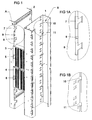
- two longitudinal spars 1 and 2 are shown, which can be installed vertically in a cabinet of an automation system.
- the longitudinal spar 1 also serves to accommodate subracks.
- the two longitudinal spars 1 and 2 are arranged with their flat sides parallel to one another.
- two cuboid connection modules 3 and 4 are installed in between, two cuboid connection modules 3 and 4 are installed.
- the cuboid connection module 3 is provided with a locking lever 5, the connection module 4 with a locking lever 6.
- These locking levers 5 and 6 have locking lugs (not visible in FIG. 1) which are locked in perforations in the longitudinal spar 2 and fix the position of the connection modules 3 and 4.
- perforations 7 and 8 are provided, which are L-shaped and are arranged such that the first leg begins almost at right angles on the side edge and the second leg runs parallel to the side edge downwards .
- Corresponding perforations for the tabs on the other side of the connection module are located on the opposite side of the longitudinal spar 1 and are covered in FIG. 1.
- a perforation 9 is for the locking lug of the locking lever intended.
- section A with the perforations 7, 8 and 9 described is shown enlarged again.
- connection module For installation, a connection module is first inserted with its tabs on the right-hand side into the invisible perforations of the longitudinal spar 1, then aligned with its sides parallel to the sides of the longitudinal spars 1 and 2 and moved parallel backwards and downwards until it is is in its end position. In the end position, the locking lug of the locking lever, which is pressed against the longitudinal spar 2 by spring force, automatically engages.
- the connection module is fixed in its position to the rear, front and bottom. The position of the connection panel upwards is achieved by the locking connection of the locking lug of the locking lever and the corresponding perforation 9 in the longitudinal spar 2.
- connection modules are located in the rear space between the two longitudinal spars 1 and 2. Connection modules can be installed there so that their connection elements are accessible from the rear and the locking lever is seen from the rear on the right side.
- the perforations 10 and 11 required for installation for the tabs on the left-hand side of a connection module, which are located in cutout B, are shown enlarged in the detailed drawing in FIG. 1B.
- a cuboid connection module essentially consists of a housing 12 and a printed circuit board 13 which is equipped with screw or spring-loaded terminals 14. These are arranged in 24 rows with four terminals per row. The pitch from row to row is 5.08 mm. The outer and the inner two terminals are each electrically connected to a conductor track on the printed circuit board 13. This results in 48 passes per connection module.
- the printed circuit board 13 is inserted into the plastic housing 12 and not there by one in FIG. 2 visible locking connection held.
- the plastic housing 12 has an opening 15 in the region of each terminal for the application of a line and an opening 16 for an actuating tool.
- a central elevation 17 of the plastic housing 12 serves as a receptacle for an identification strip of the connection line.
- the circuit board 13 has on the right and left side two fastening tabs which protrude beyond the plastic housing 12 in the installed state. In Figure 2, only the two tabs 18 and 19 are visible.
- a locking lever 20 is resiliently suspended from the plastic housing 12 and protrudes from the front thereof.
- the connection module can advantageously be removed with one hand by the thumb operating the locking lever 20 and the remaining fingers reaching behind the central elevation 17 of the plastic housing 12. After the snap connection is unlocked, the connection module is lifted up and pulled out to the front.
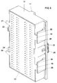
- connection module In the rear view of the connection module according to Figure 3, the mounting tabs 21 and 22 are visible, which are located on the right side of the connection module when viewed from the front. In addition, locking lugs 23 and 24 are arranged, which fix the circuit board 13 in the housing 12. Reference symbols already introduced in FIG. 2 are also used in FIG. 3 for identical parts. A latch 25 of the locking lever 20 snaps into the opening 9 of the longitudinal spar 2 (FIG. 1, 1A) when the cuboid connection module is installed and locks the connection module.
- Guide grooves 26 on the plastic housing 12 ensure parallel displacement of the connection module along the sides of the longitudinal spars 1 and 2, for a clear positional fixation of the connection module on the longitudinal spar 2 and for a reliable function of the latching connection of the locking lever 20 the longitudinal spars 1 and 2 easily manageable.
Landscapes
- Engineering & Computer Science (AREA)
- Automation & Control Theory (AREA)
- Microelectronics & Electronic Packaging (AREA)
- Casings For Electric Apparatus (AREA)
Abstract
Description
Die Erfindung betrifft eine Vorrichtung zur Befestigung eines quaderförmigen Anschlußmoduls an einem Träger nach dem Oberbegriff des Anspruchs 1 sowie einen Schrank mit einer derartigen Vorrichtung nach dem Oberbegriff des Anspruchs 6.The invention relates to a device for fastening a cuboid connection module to a carrier according to the preamble of
In der DE-GM 93 11 526 ist ein Schrankgestell eines Automatisierungssystems beschrieben, welches aus Längs- und Querholmen besteht. In das Gestell sind Baugruppenträger eingebaut, die mit Baugruppen, z. B. digitalen Ein- und Ausgabebaugruppen, bestückt sind.DE-GM 93 11 526 describes a cabinet frame of an automation system which consists of longitudinal and transverse bars. In the frame subracks are built, which with modules such. B. digital input and output modules are equipped.
In derartigen Schränken müssen Signalleitungen, die von der Prozeßperipherie kommen, mit der Auswertungselektronik, die sich in den Baugruppenträgern befindet, verbunden werden. Neben einer reinrassigen Bestückung dieser Schränke mit nur einer Gerätefamilie sind häufig auch Schränke mit gemischter Bestückung unterschiedlicher Gerätefamilien erforderlich. Unterschiedliche Gerätefamilien erfordern auch eine unterschiedliche Anschlußtechnik für die Prozeßperipherie. Periphere Leitungen können somit nicht direkt auf die Anschlußstellen der Baugruppenträger aufgelegt werden, da die Leitungen häufig nicht der erforderlichen Anschlußtechnik entsprechen. Sie werden also zunächst auf zusätzliche Anschlußelemente geführt, die wiederum selbst durch geeignete Leitungen mit den Anschlußstellen der Auswertungselektronik verbunden sind. Als Anschlußelemente sind beispielsweise Reihenklemmen geeignet, die von verschiedenen Herstellern angeboten werden. Diese Reihenklemmen benötigen zur Montage ein Standardprofil, das auch als Hutschiene bezeichnet wird. Nachteilig bei diesen Reihenklemmen ist ihr großer Raumbedarf, da sie zusätzlich im Innenraum des Schranks untergebracht werden müssen. Weiterhin ist die Verwendung einer Hutschiene als Montageträger der Reihenklemmen von Nachteil, da aufgrund der unterschiedlichen Bestückungsvarianten der Schränke eine Vielzahl von Längenvarianten der Hutschiene erforderlich wären. Dies würde die Disposition und Lagerhaltung erheblich erschweren und somit das Automatisierungssystem verteuern.In such cabinets, signal lines that come from the process periphery must be connected to the evaluation electronics that are located in the subracks. In addition to purely equipping these cabinets with just one device family, cabinets with mixed equipment from different device families are often required. Different device families also require different connection technology for the process periphery. Peripheral cables can therefore not be placed directly on the connection points of the subracks, since the cables often do not correspond to the required connection technology. They are therefore initially routed to additional connection elements, which in turn are themselves connected to the connection points of the evaluation electronics by suitable lines. Terminal blocks, for example, which are offered by various manufacturers, are suitable as connecting elements. These terminal blocks require a standard profile for assembly, which is also known as a DIN rail. A disadvantage of these terminal blocks is their large space requirement, since they are also housed in the interior of the cabinet Need to become. Furthermore, the use of a top-hat rail as a mounting bracket for the terminal blocks is disadvantageous, since a large number of length variants of the top-hat rail would be required due to the different mounting variants of the cabinets. This would make scheduling and warehousing considerably more difficult and thus make the automation system more expensive.
Der Erfindung liegt die Aufgabe zugrunde, eine Vorrichtung zur Befestigung eines quaderförmigen Anschlußmoduls an einen Träger zu schaffen, die es ermöglicht, mit geringem Montageaufwand Anschlußmodule auf engem Raum, beispielsweise in einem Schrank eines Automatisierungssystems, unterzubringen. Eine weitere Aufgabe ist es, einen Schrank mit einer derartigen Vorrichtung auszurüsten.The invention has for its object to provide a device for attaching a cuboid connection module to a carrier, which makes it possible to accommodate connection modules in a small space, for example in a cabinet of an automation system, with little installation effort. Another object is to equip a cabinet with such a device.
Die Erfindung hat den Vorteil, daß quaderförmige Anschlußmodule ohne zusätzliches Werkzeug schnell in Schränken montierbar sind. Die Montage kann auch nachträglich erfolgen. Die quaderförmigen Anschlußmodule sind modular aneinanderreihbar und können mit einer durchgängigen Beschriftung versehen werden. Mit den Anschlußmodulen kann flexibel und modular auf die unterschiedlichen Anschlußtechniken der verschiedenen Gerätefamilien reagiert werden. Dabei ist die erfindungsgemäße Vorrichtung mit geringem Zusatzaufwand in die bekannte Aufbautechnik integrierbar. Bei einer Bestückung der quaderförmigen Anschlußmodule mit Schraub- oder Federkraftklemmen können Leitungen mit einem Anschlußquerschnitt von 0,5 mm2 bis 2,5 mm2 eingelegt werden. Pro Volumeneinheit werden sehr viele Anschlußpunkte möglich. Dabei sind Aufwand und Kosten je Anschlußelement gegenüber Reihenklemmen mit Hutschienen gering. Die Verdrahtung von Ein- und Ausgangsseite des quaderförmigen Anschlußmoduls ist übersichtlich, frei zugänglich und gut handhabbar.The invention has the advantage that cuboid connection modules can be quickly installed in cabinets without additional tools. The assembly can also be done later. The cuboid connection modules can be arranged in a modular manner and can be provided with a continuous label. With the connection modules you can react flexibly and modularly to the different connection technologies of the different device families. The device according to the invention can be integrated into the known construction technology with little additional effort. If the cuboid connection modules are equipped with screw or spring-loaded terminals, cables with a connection cross section of 0.5 mm 2 to 2.5 mm 2 can be inserted. Many connection points are possible per volume unit. The effort and cost per connection element are low compared to terminal blocks with top-hat rails. The wiring from the input and output side of the cuboid connection module is clear, freely accessible and easy to handle.
Anhand der Zeichnungen, in denen ein Ausführungsbeispiel der Erfindung dargestellt ist, werden im folgenden die Erfindung sowie Ausgestaltungen und Vorteile näher erläutert.Based on the drawings, in which an embodiment of the invention is shown, the invention and embodiments and advantages are explained in more detail below.
Es zeigen:
Figur 1- - an einem Träger befestigte Anschlußmodule,
- Figuren 1A und 1B
- - Ausschnitte aus
Figur 1, Figur 2- ein geöffnetes quaderförmiges Anschlußmodul und
Figur 3- eine Rückansicht eines zusammengebauten Anschlußmoduls.
- Figure 1
- - connection modules attached to a carrier,
- Figures 1A and 1B
- - sections from FIG. 1,
- Figure 2
- an open cuboid connection module and
- Figure 3
- a rear view of an assembled connection module.
In Figur 1 sind zwei Längsholme 1 und 2 dargestellt, die in einem Schrank eines Automatisierungssystems senkrecht eingebaut werden können. Der Längsholm 1 dient auch zur Aufnahme von Baugruppenträgern. Die beiden Längsholme 1 und 2 sind mit ihren flachen Seiten parallel zueinander angeordnet. Dazwischen sind zwei quaderförmige Anschlußmodule 3 und 4 eingebaut. Das quaderförmige Anschlußmodul 3 ist mit einem Verriegelungshebel 5, das Anschlußmodul 4 mit einem Verriegelungshebel 6 versehen. Diese Verriegelungshebel 5 und 6 weisen in Figur 1 nicht sichtbare Rastnasen auf, die in Perforationen des Längsholms 2 eingerastet sind und die Lage der Anschlußmodule 3 und 4 fixieren. Oberhalb des Anschlußmoduls 3 sowie unterhalb des Anschlußmoduls 4 befindet sich jeweils ein Einbauplatz für ein weiteres Anschlußmodul. An dem freien Einbauplatz oberhalb des Anschlußmoduls 3 sind im Ausschnitt A die zum Einbau eines Anschlußmoduls vorgesehenen Perforationen im Längsholm 2 gut sichtbar. Für an der Rückseite eines Anschlußmoduls befindliche, nach außen ragende, senkrechte Laschen sind Perforationen 7 und 8 vorgesehen, die L-förmig ausgebildet und derart angeordnet sind, daß der erste Schenkel nahezu rechtwinklig am Seitenrand beginnt und der zweite Schenkel parallel zum Seitenrand nach unten verläuft. Auf der gegenüberliegenden Seite des Längsholms 1 befinden sich dazu korrespondierende Perforationen für die Laschen der anderen Seite des Anschlußmoduls, die in Figur 1 verdeckt sind. Eine Perforation 9 ist für die Rastnase des Verriegelungshebels vorgesehen. In Figur 1A ist der Ausschnitt A mit den beschriebenen Perforationen 7, 8 und 9 noch einmal vergrößert dargestellt. Zum Einbau wird ein Anschlußmodul zuerst mit seinen an der rechten Seite befindlichen Laschen in die nicht sichtbaren Perforationen des Längsholms 1 eingelegt, dann mit seinen Seiten parallel zu den Seiten der Längsholme 1 und 2 ausgerichtet und parallel nach hinten und nach unten verschoben, bis er sich in seiner Endlage befindet. In der Endlage rastet selbständig die Rastnase des Verriegelungshebels, der durch Federkraft gegen den Längsholm 2 gedrückt wird, ein. Durch das Zusammenwirken der Laschen und der in Figur 1 nicht sichtbaren Perforationen im Längsholm 1 sowie der Perforationen 7 und 8 im Längsholm 2 wird das Anschlußmodul in seiner Lage nach hinten, vorne und unten fixiert. Die Lagefixierung des Anschlußfeldes nach oben wird durch die Rastverbindung der Rastnase des Verriegelungshebels und der korrespondierenden Perforation 9 im Längsholm 2 erreicht. Weitere Einbauplätze für quaderförmige Schrankanschlußmodule befinden sich im rückseitigen Zwischenraum zwischen den beiden Längsholmen 1 und 2. Anschlußmodule können dort so eingebaut werden, daß ihre Anschlußelemente von der Rückseite aus zugänglich sind und sich der Verriegelungshebel von der Rückseite aus gesehen auf der rechten Seite befindet. Die zum Einbau erforderlichen Perforationen 10 und 11 für die Laschen auf der linken Seite eines Anschlußmoduls, die sich im Ausschnitt B befinden, sind in der Detailzeichnung Figur 1B vergrößert dargestellt.In Figure 1, two
Ein quaderförmiges Anschlußmodul besteht nach Figur 2 im wesentlichen aus einem Gehäuse 12 und einer Leiterplatte 13, die mit Schraub- oder Federkraftklemmen 14 bestückt ist. Diese sind in 24 Zeilen mit je vier Klemmen pro Zeile angeordnet. Der Teilungsabstand von Zeile zu Zeile beträgt 5,08 mm. Die äußeren sowie die inneren beiden Klemmen sind je mit einer Leiterbahn auf der Leiterplatte 13 elektrisch verbunden. Damit ergeben sich 48 Durchgänge je Anschlußmodul. Die bestückte Leiterplatte 13 wird in das Kunststoffgehäuse 12 eingelegt und dort durch eine in Figur 2 nicht sichtbare Rastverbindung gehalten. Das Kunststoffgehäuse 12 hat im Bereich jeder Klemme eine Öffnung 15 zum Anlegen einer Leitung und eine Öffnung 16 für ein Betätigungswerkzeug. Eine mittige Erhöhung 17 des Kunststoffgehäuses 12 dient als Aufnahme für einen Kennzeichnungsstreifen der Anschlußzeile. Die Leiterplatte 13 besitzt auf der rechten und linken Seite je zwei Befestigungslaschen, die im eingebauten Zustand über das Kunststoffgehäuse 12 hinausragen. In Figur 2 sind lediglich die beiden Laschen 18 und 19 sichtbar. Ein Verriegelungshebel 20 ist federnd am Kunststoffgehäuse 12 aufgehängt und ragt über dessen Frontseite heraus. Der Ausbau des Anschlußmoduls kann vorteilhaft mit einer Hand erfolgen, indem der Daumen den Verriegelungshebel 20 bedient und die restlichen Finger hinter die mittige Erhöhung 17 des Kunststoffgehäuses 12 greifen. Nachdem die Rastverbindung entriegelt ist, wird das Anschlußmodul nach oben angehoben und nach vorne herausgezogen.According to FIG. 2, a cuboid connection module essentially consists of a
In der Rückansicht des Anschlußmoduls nach Figur 3 sind auch die Befestigungslaschen 21 und 22 sichtbar, die sich von der Vorderseite aus gesehen auf der rechten Seite des Anschlußmoduls befinden. Daneben sind Rastnasen 23 und 24 angeordnet, welche die Leiterplatte 13 im Gehäuse 12 fixieren. Bereits in Figur 2 eingeführte Bezugszeichen werden für gleiche Teile auch in Figur 3 verwendet. Eine Rastnase 25 des Verriegelungshebels 20 rastet beim Einbau des quaderförmigen Anschlußmoduls in die Öffnung 9 des Längsholms 2 (Figur 1, 1A) ein und verriegelt das Anschlußmodul. Führungsnuten 26 am Kunststoffgehäuse 12 sorgen für paralleles Verschieben des Anschlußmoduls entlang der Seiten der Längsholme 1 und 2, für eine eindeutige Lagefixierung des Anschlußmoduls an dem Längsholm 2 und für eine sichere Funktion der Rastverbindung des Verriegelungshebels 20. Durch die Führungsnuten 26 sind zudem größere Abstandstoleranzen zwischen den Längsholmen 1 und 2 leicht beherrschbar.In the rear view of the connection module according to Figure 3, the mounting
Claims (7)
Applications Claiming Priority (2)
| Application Number | Priority Date | Filing Date | Title |
|---|---|---|---|
| DE29506631U | 1995-04-19 | ||
| DE29506631U DE29506631U1 (en) | 1995-04-19 | 1995-04-19 | Device for fastening a cuboid connection module to a carrier and cabinet with such a device |
Publications (3)
| Publication Number | Publication Date |
|---|---|
| EP0739158A2 true EP0739158A2 (en) | 1996-10-23 |
| EP0739158A3 EP0739158A3 (en) | 1997-05-21 |
| EP0739158B1 EP0739158B1 (en) | 1999-03-10 |
Family
ID=8007035
Family Applications (1)
| Application Number | Title | Priority Date | Filing Date |
|---|---|---|---|
| EP19960105958 Expired - Lifetime EP0739158B1 (en) | 1995-04-19 | 1996-04-16 | Device for fastening a connection module to a support and cabinet with said device |
Country Status (4)
| Country | Link |
|---|---|
| EP (1) | EP0739158B1 (en) |
| DE (2) | DE29506631U1 (en) |
| DK (1) | DK0739158T3 (en) |
| ES (1) | ES2130710T3 (en) |
Cited By (1)
| Publication number | Priority date | Publication date | Assignee | Title |
|---|---|---|---|---|
| EP0924806A1 (en) * | 1997-12-17 | 1999-06-23 | Berg Electronics Manufacturing B.V. | Connectors with floating terminals and a terminal for such a connector |
Citations (8)
| Publication number | Priority date | Publication date | Assignee | Title |
|---|---|---|---|---|
| DE3209205A1 (en) * | 1982-03-13 | 1983-09-22 | Licentia Patent-Verwaltungs-Gmbh, 6000 Frankfurt | Guide holder for electronic assemblies |
| DE3409022A1 (en) * | 1984-03-13 | 1985-09-19 | Brown, Boveri & Cie Ag, 6800 Mannheim | Mounting rack for electronic apparatuses |
| FR2579138A1 (en) * | 1985-03-21 | 1986-09-26 | Achat Distr Articles Classemen | Modular storage box |
| FR2580869A1 (en) * | 1985-04-23 | 1986-10-24 | Amp Inc | Modular closure element for an electrical connector and this connector |
| DE3704128A1 (en) * | 1987-02-11 | 1988-08-25 | Bbc Brown Boveri & Cie | Electronics cabinet having mounting units arranged therein |
| US5095403A (en) * | 1990-03-08 | 1992-03-10 | Merlin Gerin | Low voltage switchboard |
| US5287428A (en) * | 1991-10-16 | 1994-02-15 | Fujitsu Limited | Optical fiber cable distribution apparatus |
| DE9311526U1 (en) * | 1993-08-02 | 1994-09-15 | Siemens Ag | Arrangement for the electrical connection of components with electrical conductors |
-
1995
- 1995-04-19 DE DE29506631U patent/DE29506631U1/en not_active Expired - Lifetime
-
1996
- 1996-04-16 DE DE59601406T patent/DE59601406D1/en not_active Expired - Fee Related
- 1996-04-16 EP EP19960105958 patent/EP0739158B1/en not_active Expired - Lifetime
- 1996-04-16 ES ES96105958T patent/ES2130710T3/en not_active Expired - Lifetime
- 1996-04-16 DK DK96105958T patent/DK0739158T3/en active
Patent Citations (8)
| Publication number | Priority date | Publication date | Assignee | Title |
|---|---|---|---|---|
| DE3209205A1 (en) * | 1982-03-13 | 1983-09-22 | Licentia Patent-Verwaltungs-Gmbh, 6000 Frankfurt | Guide holder for electronic assemblies |
| DE3409022A1 (en) * | 1984-03-13 | 1985-09-19 | Brown, Boveri & Cie Ag, 6800 Mannheim | Mounting rack for electronic apparatuses |
| FR2579138A1 (en) * | 1985-03-21 | 1986-09-26 | Achat Distr Articles Classemen | Modular storage box |
| FR2580869A1 (en) * | 1985-04-23 | 1986-10-24 | Amp Inc | Modular closure element for an electrical connector and this connector |
| DE3704128A1 (en) * | 1987-02-11 | 1988-08-25 | Bbc Brown Boveri & Cie | Electronics cabinet having mounting units arranged therein |
| US5095403A (en) * | 1990-03-08 | 1992-03-10 | Merlin Gerin | Low voltage switchboard |
| US5287428A (en) * | 1991-10-16 | 1994-02-15 | Fujitsu Limited | Optical fiber cable distribution apparatus |
| DE9311526U1 (en) * | 1993-08-02 | 1994-09-15 | Siemens Ag | Arrangement for the electrical connection of components with electrical conductors |
Cited By (1)
| Publication number | Priority date | Publication date | Assignee | Title |
|---|---|---|---|---|
| EP0924806A1 (en) * | 1997-12-17 | 1999-06-23 | Berg Electronics Manufacturing B.V. | Connectors with floating terminals and a terminal for such a connector |
Also Published As
| Publication number | Publication date |
|---|---|
| EP0739158A3 (en) | 1997-05-21 |
| DE59601406D1 (en) | 1999-04-15 |
| EP0739158B1 (en) | 1999-03-10 |
| DE29506631U1 (en) | 1996-05-30 |
| ES2130710T3 (en) | 1999-07-01 |
| DK0739158T3 (en) | 1999-10-04 |
Similar Documents
| Publication | Publication Date | Title |
|---|---|---|
| EP0677986B1 (en) | Assembly of an automation apparatus | |
| EP2005486A2 (en) | Electrical connecting device for flat conductors | |
| DE102008033430B4 (en) | Distribution terminal module for telecommunications and data technology | |
| DE212016000059U1 (en) | Rail-mountable control system with improved attachment | |
| DE3719689C1 (en) | Arrangement of modular assemblies | |
| DE4113559A1 (en) | CONNECTOR MOUNTING ARRANGEMENT | |
| EP0702441B1 (en) | Electrical installation apparatus, especially for cable ducts | |
| EP1159158A1 (en) | Metal housing, especially for an airbag control device | |
| DE4232622C1 (en) | Contacting device for connecting a conductor foil having a plurality of contact conductor tracks | |
| EP0844691A2 (en) | Decentralised data in and out modul for databus | |
| EP1867021B1 (en) | Electric switching system and base module for an electric switching system | |
| DE4001104A1 (en) | Plug connector for PCB - is flexible enough to allow interchanging of connection arrangement and connected elements | |
| DE19507724C1 (en) | Mechanical coding device for plug-in circuit module reception location | |
| WO2001069994A2 (en) | Extendable housing consisting of assembly frames | |
| EP0739158A2 (en) | Device for fastening a connection module to a support and cabinet with said device | |
| DE4301602C1 (en) | Electrical connector part with synthetic housing - has guide rails leading from entry opening of admission chamber to plug-in opening for mating contact element | |
| DE3417451A1 (en) | Plug-in housing | |
| DE202005020655U1 (en) | Carrier unit for forming terminal strip, has closing walls spaced from each other and slots for retaining respective connecting terminals that are fixed to unit at its front/bottom sides, where terminals are fixed in slots using fastener | |
| DE19610037C2 (en) | Subrack | |
| DE3144535C2 (en) | Display device with liquid crystal display | |
| WO1998047336A1 (en) | Electrical appliance with two identically built casing shells | |
| EP0886992B1 (en) | Equipment chassis for electronic equipment | |
| DE3201169C2 (en) | Device for clamping electrical conductors, in particular wires | |
| DE3208161A1 (en) | Switch box and/or distribution box for the installation of electrical installation apparatuses | |
| DE3409021A1 (en) | Device for attaching and ejecting electronic assemblies |
Legal Events
| Date | Code | Title | Description |
|---|---|---|---|
| PUAI | Public reference made under article 153(3) epc to a published international application that has entered the european phase |
Free format text: ORIGINAL CODE: 0009012 |
|
| AK | Designated contracting states |
Kind code of ref document: A2 Designated state(s): BE CH DE DK ES FR GB IT LI NL SE |
|
| PUAL | Search report despatched |
Free format text: ORIGINAL CODE: 0009013 |
|
| AK | Designated contracting states |
Kind code of ref document: A3 Designated state(s): BE CH DE DK ES FR GB IT LI NL SE |
|
| 17P | Request for examination filed |
Effective date: 19970617 |
|
| GRAG | Despatch of communication of intention to grant |
Free format text: ORIGINAL CODE: EPIDOS AGRA |
|
| 17Q | First examination report despatched |
Effective date: 19980622 |
|
| GRAG | Despatch of communication of intention to grant |
Free format text: ORIGINAL CODE: EPIDOS AGRA |
|
| GRAH | Despatch of communication of intention to grant a patent |
Free format text: ORIGINAL CODE: EPIDOS IGRA |
|
| GRAH | Despatch of communication of intention to grant a patent |
Free format text: ORIGINAL CODE: EPIDOS IGRA |
|
| GRAA | (expected) grant |
Free format text: ORIGINAL CODE: 0009210 |
|
| AK | Designated contracting states |
Kind code of ref document: B1 Designated state(s): BE CH DE DK ES FR GB IT LI NL SE |
|
| REG | Reference to a national code |
Ref country code: CH Ref legal event code: NV Representative=s name: SIEMENS SCHWEIZ AG Ref country code: CH Ref legal event code: EP |
|
| REF | Corresponds to: |
Ref document number: 59601406 Country of ref document: DE Date of ref document: 19990415 |
|
| ET | Fr: translation filed | ||
| GBT | Gb: translation of ep patent filed (gb section 77(6)(a)/1977) |
Effective date: 19990511 |
|
| REG | Reference to a national code |
Ref country code: ES Ref legal event code: FG2A Ref document number: 2130710 Country of ref document: ES Kind code of ref document: T3 |
|
| REG | Reference to a national code |
Ref country code: DK Ref legal event code: T3 |
|
| PLBE | No opposition filed within time limit |
Free format text: ORIGINAL CODE: 0009261 |
|
| STAA | Information on the status of an ep patent application or granted ep patent |
Free format text: STATUS: NO OPPOSITION FILED WITHIN TIME LIMIT |
|
| 26N | No opposition filed | ||
| REG | Reference to a national code |
Ref country code: GB Ref legal event code: IF02 |
|
| PGFP | Annual fee paid to national office [announced via postgrant information from national office to epo] |
Ref country code: GB Payment date: 20020409 Year of fee payment: 7 Ref country code: DK Payment date: 20020409 Year of fee payment: 7 |
|
| PGFP | Annual fee paid to national office [announced via postgrant information from national office to epo] |
Ref country code: NL Payment date: 20020410 Year of fee payment: 7 |
|
| PGFP | Annual fee paid to national office [announced via postgrant information from national office to epo] |
Ref country code: ES Payment date: 20020419 Year of fee payment: 7 |
|
| PGFP | Annual fee paid to national office [announced via postgrant information from national office to epo] |
Ref country code: SE Payment date: 20020423 Year of fee payment: 7 |
|
| PGFP | Annual fee paid to national office [announced via postgrant information from national office to epo] |
Ref country code: BE Payment date: 20020426 Year of fee payment: 7 |
|
| PGFP | Annual fee paid to national office [announced via postgrant information from national office to epo] |
Ref country code: FR Payment date: 20020430 Year of fee payment: 7 |
|
| PGFP | Annual fee paid to national office [announced via postgrant information from national office to epo] |
Ref country code: DE Payment date: 20020618 Year of fee payment: 7 |
|
| PGFP | Annual fee paid to national office [announced via postgrant information from national office to epo] |
Ref country code: CH Payment date: 20020711 Year of fee payment: 7 |
|
| PG25 | Lapsed in a contracting state [announced via postgrant information from national office to epo] |
Ref country code: GB Free format text: LAPSE BECAUSE OF NON-PAYMENT OF DUE FEES Effective date: 20030416 |
|
| PG25 | Lapsed in a contracting state [announced via postgrant information from national office to epo] |
Ref country code: SE Free format text: LAPSE BECAUSE OF NON-PAYMENT OF DUE FEES Effective date: 20030417 |
|
| PG25 | Lapsed in a contracting state [announced via postgrant information from national office to epo] |
Ref country code: ES Free format text: LAPSE BECAUSE OF NON-PAYMENT OF DUE FEES Effective date: 20030419 |
|
| PG25 | Lapsed in a contracting state [announced via postgrant information from national office to epo] |
Ref country code: LI Free format text: LAPSE BECAUSE OF NON-PAYMENT OF DUE FEES Effective date: 20030430 Ref country code: DK Free format text: LAPSE BECAUSE OF NON-PAYMENT OF DUE FEES Effective date: 20030430 Ref country code: CH Free format text: LAPSE BECAUSE OF NON-PAYMENT OF DUE FEES Effective date: 20030430 Ref country code: BE Free format text: LAPSE BECAUSE OF NON-PAYMENT OF DUE FEES Effective date: 20030430 |
|
| BERE | Be: lapsed |
Owner name: *SIEMENS A.G. Effective date: 20030430 |
|
| PG25 | Lapsed in a contracting state [announced via postgrant information from national office to epo] |
Ref country code: NL Free format text: LAPSE BECAUSE OF NON-PAYMENT OF DUE FEES Effective date: 20031101 Ref country code: DE Free format text: LAPSE BECAUSE OF NON-PAYMENT OF DUE FEES Effective date: 20031101 |
|
| NLV4 | Nl: lapsed or anulled due to non-payment of the annual fee |
Effective date: 20031101 |
|
| EUG | Se: european patent has lapsed | ||
| GBPC | Gb: european patent ceased through non-payment of renewal fee |
Effective date: 20030416 |
|
| REG | Reference to a national code |
Ref country code: DK Ref legal event code: EBP |
|
| REG | Reference to a national code |
Ref country code: CH Ref legal event code: PL |
|
| PG25 | Lapsed in a contracting state [announced via postgrant information from national office to epo] |
Ref country code: FR Free format text: LAPSE BECAUSE OF NON-PAYMENT OF DUE FEES Effective date: 20031231 |
|
| REG | Reference to a national code |
Ref country code: FR Ref legal event code: ST |
|
| REG | Reference to a national code |
Ref country code: ES Ref legal event code: FD2A Effective date: 20030419 |
|
| PG25 | Lapsed in a contracting state [announced via postgrant information from national office to epo] |
Ref country code: IT Free format text: LAPSE BECAUSE OF NON-PAYMENT OF DUE FEES Effective date: 20050416 |