EP0738904B1 - Adaptive illumination device, in particular vehicle headlight - Google Patents
Adaptive illumination device, in particular vehicle headlight Download PDFInfo
- Publication number
- EP0738904B1 EP0738904B1 EP96106114A EP96106114A EP0738904B1 EP 0738904 B1 EP0738904 B1 EP 0738904B1 EP 96106114 A EP96106114 A EP 96106114A EP 96106114 A EP96106114 A EP 96106114A EP 0738904 B1 EP0738904 B1 EP 0738904B1
- Authority
- EP
- European Patent Office
- Prior art keywords
- microoptics
- matrix
- illumination device
- adaptive illumination
- elements
- Prior art date
- Legal status (The legal status is an assumption and is not a legal conclusion. Google has not performed a legal analysis and makes no representation as to the accuracy of the status listed.)
- Expired - Lifetime
Links
- 238000005286 illumination Methods 0.000 title claims description 41
- 230000003044 adaptive effect Effects 0.000 title claims description 40
- 239000011159 matrix material Substances 0.000 claims description 122
- 230000003287 optical effect Effects 0.000 claims description 58
- 238000007493 shaping process Methods 0.000 claims description 11
- 230000004075 alteration Effects 0.000 claims description 6
- 230000001747 exhibiting effect Effects 0.000 claims description 5
- 230000010287 polarization Effects 0.000 claims description 4
- 238000012937 correction Methods 0.000 claims description 2
- 230000004048 modification Effects 0.000 claims description 2
- 238000012986 modification Methods 0.000 claims description 2
- 230000004044 response Effects 0.000 claims description 2
- 238000013519 translation Methods 0.000 claims description 2
- 230000000737 periodic effect Effects 0.000 claims 1
- 239000000243 solution Substances 0.000 description 9
- 230000001427 coherent effect Effects 0.000 description 5
- 230000000694 effects Effects 0.000 description 5
- 239000011521 glass Substances 0.000 description 3
- 239000000758 substrate Substances 0.000 description 3
- XAGFODPZIPBFFR-UHFFFAOYSA-N aluminium Chemical compound [Al] XAGFODPZIPBFFR-UHFFFAOYSA-N 0.000 description 2
- 229910052782 aluminium Inorganic materials 0.000 description 2
- 239000004411 aluminium Substances 0.000 description 2
- 238000013461 design Methods 0.000 description 2
- 230000004907 flux Effects 0.000 description 2
- 238000000034 method Methods 0.000 description 2
- 239000004033 plastic Substances 0.000 description 2
- 229920003023 plastic Polymers 0.000 description 2
- 239000004417 polycarbonate Substances 0.000 description 2
- 229920000515 polycarbonate Polymers 0.000 description 2
- QNRATNLHPGXHMA-XZHTYLCXSA-N (r)-(6-ethoxyquinolin-4-yl)-[(2s,4s,5r)-5-ethyl-1-azabicyclo[2.2.2]octan-2-yl]methanol;hydrochloride Chemical compound Cl.C([C@H]([C@H](C1)CC)C2)CN1[C@@H]2[C@H](O)C1=CC=NC2=CC=C(OCC)C=C21 QNRATNLHPGXHMA-XZHTYLCXSA-N 0.000 description 1
- 230000004888 barrier function Effects 0.000 description 1
- 230000005540 biological transmission Effects 0.000 description 1
- 239000011248 coating agent Substances 0.000 description 1
- 238000000576 coating method Methods 0.000 description 1
- 238000010276 construction Methods 0.000 description 1
- 230000001419 dependent effect Effects 0.000 description 1
- 238000001312 dry etching Methods 0.000 description 1
- 238000005516 engineering process Methods 0.000 description 1
- 230000002349 favourable effect Effects 0.000 description 1
- 238000001746 injection moulding Methods 0.000 description 1
- 239000007788 liquid Substances 0.000 description 1
- 238000004519 manufacturing process Methods 0.000 description 1
- 239000000463 material Substances 0.000 description 1
- 230000007246 mechanism Effects 0.000 description 1
- 239000003595 mist Substances 0.000 description 1
- 229920003229 poly(methyl methacrylate) Polymers 0.000 description 1
- 239000004926 polymethyl methacrylate Substances 0.000 description 1
- 230000008569 process Effects 0.000 description 1
- 230000006798 recombination Effects 0.000 description 1
- 238000005215 recombination Methods 0.000 description 1
- 230000006641 stabilisation Effects 0.000 description 1
- 238000011105 stabilization Methods 0.000 description 1
- 230000001629 suppression Effects 0.000 description 1
- 238000001039 wet etching Methods 0.000 description 1
Images



Classifications
-
- G—PHYSICS
- G02—OPTICS
- G02B—OPTICAL ELEMENTS, SYSTEMS OR APPARATUS
- G02B5/00—Optical elements other than lenses
- G02B5/18—Diffraction gratings
- G02B5/1876—Diffractive Fresnel lenses; Zone plates; Kinoforms
- G02B5/188—Plurality of such optical elements formed in or on a supporting substrate
-
- F—MECHANICAL ENGINEERING; LIGHTING; HEATING; WEAPONS; BLASTING
- F21—LIGHTING
- F21S—NON-PORTABLE LIGHTING DEVICES; SYSTEMS THEREOF; VEHICLE LIGHTING DEVICES SPECIALLY ADAPTED FOR VEHICLE EXTERIORS
- F21S41/00—Illuminating devices specially adapted for vehicle exteriors, e.g. headlamps
- F21S41/20—Illuminating devices specially adapted for vehicle exteriors, e.g. headlamps characterised by refractors, transparent cover plates, light guides or filters
- F21S41/25—Projection lenses
- F21S41/255—Lenses with a front view of circular or truncated circular outline
-
- F—MECHANICAL ENGINEERING; LIGHTING; HEATING; WEAPONS; BLASTING
- F21—LIGHTING
- F21S—NON-PORTABLE LIGHTING DEVICES; SYSTEMS THEREOF; VEHICLE LIGHTING DEVICES SPECIALLY ADAPTED FOR VEHICLE EXTERIORS
- F21S41/00—Illuminating devices specially adapted for vehicle exteriors, e.g. headlamps
- F21S41/20—Illuminating devices specially adapted for vehicle exteriors, e.g. headlamps characterised by refractors, transparent cover plates, light guides or filters
- F21S41/285—Refractors, transparent cover plates, light guides or filters not provided in groups F21S41/24 - F21S41/2805
-
- F—MECHANICAL ENGINEERING; LIGHTING; HEATING; WEAPONS; BLASTING
- F21—LIGHTING
- F21S—NON-PORTABLE LIGHTING DEVICES; SYSTEMS THEREOF; VEHICLE LIGHTING DEVICES SPECIALLY ADAPTED FOR VEHICLE EXTERIORS
- F21S41/00—Illuminating devices specially adapted for vehicle exteriors, e.g. headlamps
- F21S41/60—Illuminating devices specially adapted for vehicle exteriors, e.g. headlamps characterised by a variable light distribution
- F21S41/63—Illuminating devices specially adapted for vehicle exteriors, e.g. headlamps characterised by a variable light distribution by acting on refractors, filters or transparent cover plates
- F21S41/635—Illuminating devices specially adapted for vehicle exteriors, e.g. headlamps characterised by a variable light distribution by acting on refractors, filters or transparent cover plates by moving refractors, filters or transparent cover plates
-
- F—MECHANICAL ENGINEERING; LIGHTING; HEATING; WEAPONS; BLASTING
- F21—LIGHTING
- F21V—FUNCTIONAL FEATURES OR DETAILS OF LIGHTING DEVICES OR SYSTEMS THEREOF; STRUCTURAL COMBINATIONS OF LIGHTING DEVICES WITH OTHER ARTICLES, NOT OTHERWISE PROVIDED FOR
- F21V14/00—Controlling the distribution of the light emitted by adjustment of elements
- F21V14/06—Controlling the distribution of the light emitted by adjustment of elements by movement of refractors
-
- F—MECHANICAL ENGINEERING; LIGHTING; HEATING; WEAPONS; BLASTING
- F21—LIGHTING
- F21V—FUNCTIONAL FEATURES OR DETAILS OF LIGHTING DEVICES OR SYSTEMS THEREOF; STRUCTURAL COMBINATIONS OF LIGHTING DEVICES WITH OTHER ARTICLES, NOT OTHERWISE PROVIDED FOR
- F21V17/00—Fastening of component parts of lighting devices, e.g. shades, globes, refractors, reflectors, filters, screens, grids or protective cages
- F21V17/02—Fastening of component parts of lighting devices, e.g. shades, globes, refractors, reflectors, filters, screens, grids or protective cages with provision for adjustment
-
- F—MECHANICAL ENGINEERING; LIGHTING; HEATING; WEAPONS; BLASTING
- F21—LIGHTING
- F21V—FUNCTIONAL FEATURES OR DETAILS OF LIGHTING DEVICES OR SYSTEMS THEREOF; STRUCTURAL COMBINATIONS OF LIGHTING DEVICES WITH OTHER ARTICLES, NOT OTHERWISE PROVIDED FOR
- F21V5/00—Refractors for light sources
- F21V5/002—Refractors for light sources using microoptical elements for redirecting or diffusing light
-
- G—PHYSICS
- G02—OPTICS
- G02B—OPTICAL ELEMENTS, SYSTEMS OR APPARATUS
- G02B3/00—Simple or compound lenses
- G02B3/0006—Arrays
- G02B3/0037—Arrays characterized by the distribution or form of lenses
- G02B3/0043—Inhomogeneous or irregular arrays, e.g. varying shape, size, height
-
- G—PHYSICS
- G02—OPTICS
- G02B—OPTICAL ELEMENTS, SYSTEMS OR APPARATUS
- G02B3/00—Simple or compound lenses
- G02B3/0006—Arrays
- G02B3/0037—Arrays characterized by the distribution or form of lenses
- G02B3/0056—Arrays characterized by the distribution or form of lenses arranged along two different directions in a plane, e.g. honeycomb arrangement of lenses
-
- G—PHYSICS
- G02—OPTICS
- G02B—OPTICAL ELEMENTS, SYSTEMS OR APPARATUS
- G02B5/00—Optical elements other than lenses
- G02B5/18—Diffraction gratings
- G02B5/1876—Diffractive Fresnel lenses; Zone plates; Kinoforms
- G02B5/188—Plurality of such optical elements formed in or on a supporting substrate
- G02B5/1885—Arranged as a periodic array
Definitions
- the present invention relates to an adaptive illumination device which is particularly useful for use as a vehicle headlight.
- the shaping of the light beam emitted by a headlight should be modified dynamically as a function of the conditions of travel of the vehicle, for example taking account of the speed, of the steering angle, of the inclination of the road and/or of the vehicle (this being linked with the latter's conditions of load), as well as of the meteorological conditions (fog, rain) and/or of external factors (illumination).
- the simplest of such dynamical shapings is the passage from main beam to dipped beam when crossing with other vehicles.
- vergence is understood to mean the angle of aperture of the beam (which, when it is equal to 0° defines collimated beams, all the rays being parallel, when it is greater than 0° defines divergent beams and, when it is less than 0°, defines convergent beams).
- geometric characteristics is to be intended the totality of the geometrical characteristics which govern the propagation of a beam, i.e. its direction, its inclination with respect to the optical axis of the illumination device, and its vergence.
- the aim of the invention is to provide an adaptive illumination device, i.e. one capable of rapidly varying not only the vergence, but also all the other distribution parameters of an emitted light beam, in such a way as to be able to adapt, in the case of vehicle headlights, the light emitted to the conditions of travel and/or ambient conditions, using any single light source.
- the aim of the invention is also to provide a compact and reliable device which is relatively simple to construct.
- an adaptive illumination device in particular a vehicle headlight, able to selectively emit a plurality of light beams with different preset characteristics, of the type comprising a light source, a first and a second transparent support arranged in front of the source and provided, respectively, with first and second optical elements, a reflector arranged on the opposite side from the supports in order to direct towards the latter respective light rays emitted by the source not directly towards the supports, and actuator means for moving the supports relatively in front of the source; wherein the first optical elements are each defined by an individual microoptic and are arranged on the first support in the form of a first microoptics matrix able to generate, for each element, a corresponding microbeam controlled in its overall geometric characteristics; and where in the second optical elements are arranged on the second support in the form of a second microoptics matrix which is arranged in cascade with the first matrix; each said second optical element consisting either of an individual microoptic having optical characteristics varying over the area covered thereby, or of
- the second matrix of microoptics comprises a number of microoptics greater than (or equal to) that of the first optical elements of the first matrix.
- the microoptics forming the said first matrix are all mutually identical microoptics or, at most, differ from one another, exhibiting exclusively predefined phase variations with respect to one another.
- this microoptic is an hybrid one, for instance it is a microoptic shaped at its edge and so sized to comprise at least two zones apt to contribute to beam shaping in a different way.
- a suitable quantity of micromasks and of elements able to vary the intensity distribution of the beam it will be possible to convert a main beam into a dipped beam or the latter into a fog beam.
- suitable deviating microoptics in the second matrix it will be possible to vary the vergence of the beam leaving the device, in such a way as to follow a bend or a gradient.
- the variations in distribution and shape of the beam will be obtainable under the manual control of the user (for example passing from main to dipped and vice versa), or else will be controllable automatically, for example by operating the actuator means through a central control unit connected to at least one of the following sensors: steering angle sensor, vehicle speed sensor, sensor of meteorological conditions, for example wetness of the road, visibility, etc.
- the microoptics of the said first matrix are of a type each able to generate a microbeam having geometrical characteristics identical to those of at least one of the said beams with preset characteristics to be generated, and also control at least part of the intensity distribution of such a beam, the microoptics of said first matrix being of a type able to vary the intensity of each of the said microbeams individually.
- the tasks of shaping and distributing the plurality of beams which can be generated with the device of the invention become subdivided between the two matrices of microoptics, making it possible to perform with the second matrix solely intensity redistribution operations (which may go as far as the suppression of individual rays) or operations directing the microbeams generated by the first matrix.
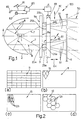
- an illumination device in this instance a vehicle headlight, essentially comprising a casing (which is known but not illustrated for the sake of simplicity) inside which are arranged a light source 1 and a reflector 2, and which is closed externally (for example in a fluid-tight manner) by a transparent screen 6 arranged somehow in front of the reflector 2 and the source 1.
- a vehicle headlight essentially comprising a casing (which is known but not illustrated for the sake of simplicity) inside which are arranged a light source 1 and a reflector 2, and which is closed externally (for example in a fluid-tight manner) by a transparent screen 6 arranged somehow in front of the reflector 2 and the source 1.
- each support 3, 4 is delimited by a respective pair of surfaces or faces, indicated respectively as 9a for the support 3 and as 9b for the support 4, arranged in series in front of the source 1 with respect to the path of the light rays 7, 8 emitted thereby.
- the reflector 2 is arranged on the opposite side from the supports 3, 4 with respect to the source 1 and is able to direct towards the faces 9a, 9b respective light rays 8 emitted by the source 1 not directly towards the faces 9a, 9b.
- these receive, directly, the rays 7 emitted by the source 1 towards the supports 3, 4.
- two matrices 10, 11 in cascade (with respect to the path of the rays 7 and 8) of optical elements 12 and, respectively, 13, are arranged on either one of the faces 9a of the support 3 and on either one of the corresponding faces 9b of the support 4.
- the light source 1 may be of any type, able to emit monochromatic, polychromatic, coherent, partially coherent or fully incoherent light; for example it may be a filament (incandescent), gas, ion discharge or solid-state polymeric bulb, or consist of a laser; in the case in which there is no desire to utilize the direct rays 7, furthermore, the source 1 can be masked in a known way with an appropriate blanking hood arranged beside the supports 3, 4.
- the reflector 2 is conversely defined by a reflecting surface generated by revolving one or more base curves and, generally, is a conventional parabolic reflector; it is therefore extremely simple and economical to construct.
- the outer transparent screen 6 is preferably completely smooth and devoid of any optical function and can therefore be made in any shape (plane, curved, etc.) and arranged at any inclination, even very steep, with respect to the optical axis A.
- the screen 6 may however also be endowed with optical functions, for example of traditional prismatics, or carry internally, on the side pointing towards the supports 3, 4, optical elements of the type of the elements 12, 13, however distributed and however made on the support.
- the matrices 11, 12 are preferably made directly on the faces 9a and 9b by injection molding of plastics such as polycarbonate or PMMA or according to a known technology are made on transparent polymeric film which is in turn applied as a liquid coating to the respective faces 9a and 9b of the substrate then UV polymerised on the substrate with the relieved master in position.
- the first matrix could be made on glass substrate; conventional stamping, dry and wet etching are usable as well.
- the optical elements 12 and 13 of the matrices 10 and 11 each consist either of an individual microoptic of any perimetral shape, or of a group 15 of a preset number, for example four, of microoptics, which are mutually identical or different from one another, arranged immediately adjacent to one another, of any perimetral shape, but however such as to be conjugate with the perimetral shape of the other adjacent microoptics of the same group.
- the size of the elements in the two matrices defines the working principle of the optical components.
- microoptics are spherical lenses refraction dominates
- the size is below 3 mm the effect of diffraction begins to be effective and the shape of the single microoptics becomes to be important for the final far field pattern to be obtained.
- the elements in the two matrices have sizes such that diffraction at the periphery defining each element is a crucial part of the design.
- hybrid optical components can be of several types for instance the single microoptics can be a spherical microlens whose centre works in refraction and the edge introduces diffraction. But it can be a high efficiency purely diffractive lens. In this case it can be supposed that the central part works like a refractive one while its periphery contributes by diffraction to define the shape of the exiting beam.
- hybrid optic is here intended as optical components, parts of a matrix, sized in such a way that the shape of the elements contributes to define the shape of the exiting pattern.
- the microoptics 12 forming the matrix 10 can all be mutually identical, for example all microoptics of hexagonal shape 12c ( Figure 2d) or else of elliptical shape 12b ( Figure 2c), or else can be microoptics having the same perimetral shape but exhibiting predefined phase variations one with respect to another, for example can consist of multifocal and/or monofocal microlenses with different focal lengths 16, 17, 18, 19, 20, 21, 22, etc.(shown schematically in Figure 3).
- the microoptics making up the optical elements 12 are each able to generate a corresponding microbeam controlled in all its geometric characteristics (vergence etc.); for example ( Figure 1) on passing through the matrix 10 the rays 7, 8 will generate respective collimated microbeams 23a and 23b, the first parallel to the optical axis A and the second inclined with respect to the axis A, respective divergent microbeams 24a, 24b at a different inclination with respect to the axis A and with a different "aperture" angle, and respective convergent microbeams 25a, 25b.
- Figure 1 on passing through the matrix 10 the rays 7, 8 will generate respective collimated microbeams 23a and 23b, the first parallel to the optical axis A and the second inclined with respect to the axis A, respective divergent microbeams 24a, 24b at a different inclination with respect to the axis A and with a different "aperture” angle, and respective convergent microbeams 25a
- each element 13 is formed by groups 15 of microoptics of rectangular ( Figures 1a, 4), rhombic ( Figure 2b) or any other shape, able to intercept selectively, in different relative positions, the microbeams 23, 24, 25, etc. emitted by the matrix 10.
- each element 73 consists of a singular complex microoptic 35 having optical characteristics varying over the area covered thereby, so as to be apt to intercept selectively microbeams 23, 24, 25 in different points of such area having different optical properties. In both cases, the optical properties of each optical element 13 of the matrix 11 are therefore dependent on the relative position of the matrix 11 with respect to the matrix 10.
- each element 12 of the first matrix there is a group 15 of microoptics in the second matrix which form a multiple element 13; the periphery enclosing that group of elements is coupled both in shape and in size to the one of the single element of the first matrix: namely, it is the perimeter or shape and size of group 15 that is equal to the single microoptics of the first array 10 (see Figure 8 and Figure 9).
- Each optical element 13 is so formed by an identical group of four mutually differing adjacent microoptics 30, 31, 32, 33, or else by ( Figures 5 and 6) mutually different groups, for example 15a, 15b, etc., of microoptics again all mutually different.
- the element of the first matrix is rectangularly shaped L x L/N
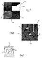
- the matrix 11 can contain one or more groups 15a each comprising four microoptics consisting of a multifocal lens 36, a multi-order grating 37, a mask 38 and a hologram 39; or groups 15b comprising for instance four microoptics (which can be two, three, five, six, etc.) consisting of a prism 40, a multi-order lens 41, an aspherical lens 42 and a cylindrical lens 43.
- the group 15a or 15b is repeated all over the matrix 11 equal to itself or for a better control of both beam shape and distribution and of the cromatism could be repeated with slightly different elements in their phase function.
- the optical elements 13 forming the matrix 11 have to be present in a number greater or equal to that of the corresponding optical elements 12 of the matrix 10, and, in every case, each must have an area greater than that projected onto the matrix 11 by each of the corresponding microbeams 23, 24, 25, etc. generated by the matrix 10, which projections are represented schematically in Figures 6 and 7 with dashed and heavy solid lines respectively.
- matrix 11 comprises always a number of microoptics greater than (or at least equal to) that of elements 12 of matrix 10.
- the microoptics 12 making up part of the first matrix 10 are chosen of a type such that the microbeams 23, 24, 25, etc. generated by them each already have, as inherent geometrical characteristics, all those same geometrical characteristics which it is desired to obtain for at least one of the overall beams 50 generated by the device 10.
- the microoptics defining the optical elements 13 of the second matrix will be chosen of a type also able to modulate in a preset manner, individually or contemporaneously, the microbeams intercepted by them in one or more of the following quantities: intensity, distribution and polarization.
- the overall beams 50 produced by the device 10 will be generated, according to the invention, by the superposition of all the microbeams generated by the microoptics 12 and, possibly, modified in their characteristics other than those which are purely geometrical, by the microoptics 13.
- Microoptics meeting this specification may be of the most disparate types; for example, each microoptic defining (or making up) a complex element 12 or 13 can be defined by a known individual optical element describable by a complex transmission function of analytical type suitably discretized, or else of digital type (for example the elements 37 and 39 of Figure 5), in which the function describes the presence of binary codes defined by relieves (high/low), continous profiles or by barriers (pass/no-pass); therefore, the microoptics defining the complex elements 12, 13 may be of pure phase, i.e. able to transmit all the incident light, or else of amplitude, i.e. which absorb or reflect a portion of the beam incident thereon; for example, the micromasks 38 to be used in the matrix 11 can be structured micromasks of the grey levels or amplitude binary type.
- phasewise differing microoptics are used for the complex elements 12, as already described, for example ones which differ from one another only through the phase constant, which varies in relation to the position of the microoptic in the matrix.
- the microoptics defining the elements 12 can be refractive microoptics, diffractive microoptics or hybrid refractive-diffractive microoptics, whereas the microoptics defining the complex elements 13 will be exclusively of diffractive or hybrid refractive-diffractive type; as already described, furthermore, the microoptics of the matrix 10 can be shaped ( Figure 2c, 2d, 8 and 9) to control not only the geometrical characteristics of the microbeams 23, 24, 25, etc., but also, at least within certain limits, to vary the intensity of each microbeam individually, in such a way as to control, already with the matrix 10, at least part of the intensity distribution of the overall beams 50, since a definite shape of outline, combined with a definite type of microoptic already provides a preset divergence; hence the appropriate combination of the geometry of the microlenses with their optical characteristics enables a modification of the shape and intensity of the individual microbeams to be obtained simultaneously.
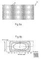
- FIG. 8a and 8b An example of rectangular microoptics is illustrated in Figures 8a and 8b.
- Figure 9a A further example is illustrated in Figure 9a where the microoptics are shaped with a periphery that defines the typical dipped beam of a headlamp. The periphery is inscribed in a rectangle size 2.5 mm x 1.2 mm. The corresponding far field pattern is illustrated in Figure 9b.
- microoptic which are preferred in order to embody the invention comprise two-level or multilevel or continuous relief, pure phase binary diffractive elements, of the computer-generated hologram type, prismatic elements of diffractive or microrefractive type and, specifically for the microoptics of the matrix 10, diffractive, refractive or hybrid general aspherical elements.
- one of the microoptics making up each group 15 of the matrix 11 is made as an element of the computer-generated hologram type (such as 39 of Figure 5) shaped in such a way as to vary the state of polarization of the microbeams intercepted by it; this variant is particularly useful for devices 10 intended to be used as headlights: in this way, in fact, by moving either the support 4 or 3 in such a way as to intercept with these elements all the microbeams generated by the matrix 10 it is possible to attenuate or prevent dazzling when crossing while preserving beams having high luminous intensity.
- some of the microoptics of the matrix 11 can also consist of plane transparent elements of the window type, so as not to vary the characteristics of the microbeams intercepted by such elements.
- Preferred optical elements for embodying the microoptics of the matrices 10 and 11 are also subwavelength diffractive structures, otherwise known as zero-order diffractive structures, or else elements able to generate a high number of light spots, of the type: fanout gratings, multi-order gratings, Dammann gratings, and their generalizations having symmetrical or asymmetrical structures.
- these particular elements make it possible to attenuate or solve, as will be seen, the problem of the generation of chromatic aberrations in the overall beam, which are connected with the shifts in the wavelength distribution of the light rays produced by microoptics. Solutions of chromatic correction are here considered as those per which at all angles of the far field both diffracted and rifracted rays overlap with relative intensities such as the beam has specified chromatic coordinate, i.e. white light.
- a first solution to the abovementioned problem consists in using for the matrix 10 microoptics exhibiting dispersive chromatic characteristics opposite to those of the corresponding microoptics of the matrix 11; so, for example, in conjunction with microoptics of diffractive type for the matrix 11, it will be necessary to use microoptics of exclusively refractive type for the matrix 10.
- a second solution to the problem is to be mindful that at least one of the two matrices 10, 11 consists exclusively of pure-phase microoptics of the kinoform type, of higher order than the first one, which consist of hybrid refractive-diffractive microlenses which are sufficiently thick to obtain refraction and are provided with relieves of different height arranged as a grating, to obtain diffraction.
- Kinoforms of order higher than four have been proved to be sufficiently adeguate for chromatic control of lighting devices.
- a further solution to the problem is to use for either the matrix 10 or 11 microoptics of monofocal type, all differing from one another and distributed in the matrix in such a way as to correct the chromatic aberrations present in the overall beam 50.
- Figure 12 is such an example of a matrix with monofocal lenses with different focals introduced to reduce the residual chromatic aberration; increased beam uniformity has been proved as well.
- microoptics composed of diffractive multifocal elements, like the elements 16, 22 schematically illustrated in Figure 3 and the real element 36 illustrated in Figure 5; this way, the microbeams generated, focused in multispots along the optical axis per each wavelength are recombined in the overall beam 50.
- the support 3 is fixed with respect to the source 1, whereas the support 4 is connected to an actuationer 5, which may be an actuator of any known type, for example an electromechanical, piezoelectric, polymorphic, magnetorestrictive, electrostatic transducer, etc., able to move the support 4 relative to 3 in accordance with one, two or more of the modes indicated by arrows in Figure 1, for example to shift the support 4 vertically and/or horizontally (i.e.
- microoptics are located in annulus such as those illustrated in Figure 11.
- Figure 11a represents the first matrix 10
- Figure 11b illustrates the second matrix 11 in cascade.
- Per each element 12 of the first matrix 10 there are group of two microoptics 15 forming a corresponding element 13 in the second matrix 11. The selection of one of the two being possible by a simple rotation of one of the matrix. Disposition of the microoptics on spirals are possible and easily implementable.
- actuator 5 or a series of actuators 5 each specialized to effect an individual movement described
- central control unit 80 which is able to receive commands from a user, via respective push-buttons/switches which are not illustrated, or else signals from, for example, a sensor 81 of the steering angle, a sensor 82 of vehicle speed, a sensor 83 of meteorological conditions (wetness, mist, etc.) so as to process them with a program stored in this facility, so as to generate respective commands for the actuator 5.
- a central control unit 80 which is able to receive commands from a user, via respective push-buttons/switches which are not illustrated, or else signals from, for example, a sensor 81 of the steering angle, a sensor 82 of vehicle speed, a sensor 83 of meteorological conditions (wetness, mist, etc.) so as to process them with a program stored in this facility, so as to generate respective commands for the actuator 5.
- each microbeam generated by the matrix 10 can be "processed” and corrected by the matrix 11 in intensity, wavelength distribution and polarization in a plurality of different ways (in this instance, at least four different ones in the case of the matrix 11 formed by groups 15 of four elements and present in identical number to that of the elements 12), consequently generating overall beams 50 with different distributional characteristics, for example provided with cut-offs, see Figure 5 element 38 (therefore suitable to constitute anti-fog beams or dipped beams), having a different vergence (therefore able to illuminate one and the same sector differently).
- control described may be accomplished not only in discrete mode, but also in continuous mode, in which case, by using microoptics such as 35, whose optical characteristics vary continuously over its area, it will for example be possible to vary the inclination (lateral and/or vertical) of the beam 50 continuously as a function of the steering angle, so as, for example, to follow a bend by rotating the beam 50 as a function of the position of the vehicle on the bend.
- the adaptive performance of the system has been implemented by a telescopic arrangement illustrated in Figure 10a where two positive microoptics are combined.
- the microoptics of the first matrix 10 is composed of squared spherical microlenses with focal F, height H and F number K
- the second matrix 11 composed of spherical microlenses with focal F/2 and the same F number K
- the F number of the overall system is halved to K/2.
- the control of the divergence can be obtained by varying the spacing between the two matrices 10 and 11.
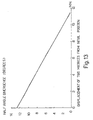
- Figure 13 illustrates the variation of the divergence of the envelope beam exiting the two matrices starting from an F number of the overall system equal 2. An actuation of few millimetre proved to be sufficient for the typical divergence adaptive control of headlamp.
- Figure 10b prooves in comparison with Figure 10a the effect of switching from one microoptic 15a of the second matrix to another microoptic 15b of the same group forming each element 13, in this case from a microlenses 15a to a prism 15b illustrated in analogical form; the beam, respectively 50a and 50b, changes its direction. This situation is particularly exiting useful in many cases of driving.
Landscapes
- Physics & Mathematics (AREA)
- Engineering & Computer Science (AREA)
- General Engineering & Computer Science (AREA)
- General Physics & Mathematics (AREA)
- Optics & Photonics (AREA)
- Non-Portable Lighting Devices Or Systems Thereof (AREA)
- Lighting Device Outwards From Vehicle And Optical Signal (AREA)
Description
- The present invention relates to an adaptive illumination device which is particularly useful for use as a vehicle headlight.
- It is known that in order to provide ideal illumination, the shaping of the light beam emitted by a headlight should be modified dynamically as a function of the conditions of travel of the vehicle, for example taking account of the speed, of the steering angle, of the inclination of the road and/or of the vehicle (this being linked with the latter's conditions of load), as well as of the meteorological conditions (fog, rain) and/or of external factors (illumination). For example, the simplest of such dynamical shapings is the passage from main beam to dipped beam when crossing with other vehicles.
- Currently, passage from one condition of illumination to the other is obtained either using multiple illumination devices (for example, main lamp, dipped lamp, fog lamp, etc.), or else using bulky, expensive and inflexible electromechanical devices, for example servo-systems which rotate the whole headlight physically with respect to the bodywork in order to vary the direction of propagation of the beam on a bend or else to vary the conditions of load of the car; or else, servo mechanisms which act on full-aperture optics (i.e. acting on the whole of the beam) arranged in cascade.
- In the field of optics, furthermore, it is known to obtain a deflection at a preset angle of a monochromatic light beam through the use of two matrices of microoptics arranged in cascade, and one of which is movable relative to the other matrix by means of piezoelectric actuators (W. Goltsoz and M. Holz, "Optical Engineering" vol. 29, page 1392, 1990). A further known solution is that of the so-called "beam expanders", i.e. a pair of convergent/divergent (or vice versa) matrices of microoptics arranged aligned along the optical axis one in front of the other, at a distance along the optical axis which can be controlled by actuators; the vergence of the beam obtained is varied by varying this distance. Here and in the following description "vergence" is understood to mean the angle of aperture of the beam (which, when it is equal to 0° defines collimated beams, all the rays being parallel, when it is greater than 0° defines divergent beams and, when it is less than 0°, defines convergent beams). On the other hand for "geometric characteristics" is to be intended the totality of the geometrical characteristics which govern the propagation of a beam, i.e. its direction, its inclination with respect to the optical axis of the illumination device, and its vergence.
- The above solutions, based on microoptics, however, besides not exhibiting, apparently, the flexibility required to solve the problem, have never been applied to headlights or, in general, to the adaptive shaping of a beam, both monochromatic and polychromatic.
- The aim of the invention is to provide an adaptive illumination device, i.e. one capable of rapidly varying not only the vergence, but also all the other distribution parameters of an emitted light beam, in such a way as to be able to adapt, in the case of vehicle headlights, the light emitted to the conditions of travel and/or ambient conditions, using any single light source. The aim of the invention is also to provide a compact and reliable device which is relatively simple to construct.
- According to the invention there is therefore constructed an adaptive illumination device, in particular a vehicle headlight, able to selectively emit a plurality of light beams with different preset characteristics, of the type comprising a light source, a first and a second transparent support arranged in front of the source and provided, respectively, with first and second optical elements, a reflector arranged on the opposite side from the supports in order to direct towards the latter respective light rays emitted by the source not directly towards the supports, and actuator means for moving the supports relatively in front of the source; wherein the first optical elements are each defined by an individual microoptic and are arranged on the first support in the form of a first microoptics matrix able to generate, for each element, a corresponding microbeam controlled in its overall geometric characteristics; and where in the second optical elements are arranged on the second support in the form of a second microoptics matrix which is arranged in cascade with the first matrix; each said second optical element consisting either of an individual microoptic having optical characteristics varying over the area covered thereby, or of a group of mutually differing microoptics arranged adjacent to one another, the second elements being sized such that in response to a relative movement such as translation, rotation or rototranslation of the two supports, said microbeams selectively intercept the second elements at different zones having different optical properties so as to contribute to beam shaping in a different way whereby adaptive shaping of the said plurality of light beams emerging from the elements of the second matrix is obtained.
- Therefore, the second matrix of microoptics comprises a number of microoptics greater than (or equal to) that of the first optical elements of the first matrix. In particular, the microoptics forming the said first matrix are all mutually identical microoptics or, at most, differ from one another, exhibiting exclusively predefined phase variations with respect to one another. Furthermore, when each said second optical element forming the second matrix of microoptics is defined by a single microoptic this microoptic is an hybrid one, for instance it is a microoptic shaped at its edge and so sized to comprise at least two zones apt to contribute to beam shaping in a different way.
- In this way, by means of suitable relative shiftings of the two supports, it is possible to cascade a plurality of mutually differing microoptics (or of regions having different optical characteristics of one and the same complex microoptic) of the second matrix with each microoptic of the first matrix, thereby obtaining the generation of a plurality of overall light beams also with mutually completely differing characteristics.
- For example, by prearranging in the second matrix a suitable quantity of micromasks and of elements able to vary the intensity distribution of the beam, it will be possible to convert a main beam into a dipped beam or the latter into a fog beam. Similarly, by prearranging suitable deviating microoptics in the second matrix, it will be possible to vary the vergence of the beam leaving the device, in such a way as to follow a bend or a gradient.
- Obviously, the variations in distribution and shape of the beam will be obtainable under the manual control of the user (for example passing from main to dipped and vice versa), or else will be controllable automatically, for example by operating the actuator means through a central control unit connected to at least one of the following sensors: steering angle sensor, vehicle speed sensor, sensor of meteorological conditions, for example wetness of the road, visibility, etc.
- Preferably, finally, the microoptics of the said first matrix are of a type each able to generate a microbeam having geometrical characteristics identical to those of at least one of the said beams with preset characteristics to be generated, and also control at least part of the intensity distribution of such a beam, the microoptics of said first matrix being of a type able to vary the intensity of each of the said microbeams individually. In this way, the tasks of shaping and distributing the plurality of beams which can be generated with the device of the invention become subdivided between the two matrices of microoptics, making it possible to perform with the second matrix solely intensity redistribution operations (which may go as far as the suppression of individual rays) or operations directing the microbeams generated by the first matrix.
- Further aims and advantages of the present invention will emerge clearly from the following description of a few non-limiting exemplary embodiments thereof, given with reference to the figures of the attached drawings, in which:
- Figure 1 represents a schematic view in elevation of a vehicle headlight made according to the invention and of its control system;
- Figure 2 illustrates schematically a few alternative embodiments of a constructional detail of the device of Figure 1;
- Figures 3 and 4 exemplify two possible types of matrices of microoptics which can be used in the device of Figure 1;
- Figures 5, 6 and 7 illustrate three different types of optical element which can be used in the device of the invention;
- Figure 8a illustrates a portion of a matrix of rectangular microlenses;
- Figure 8b illustrates the far field pattern of the matrix of microlens described in Figure 8b;
- Figure 9a illustrates microoptics shaped with the typical periphery that defines the dipped output beam of a headlamp;
- Figure 9b is the far field on a screen at 25 m given by the array of Figure 9a sized 120 mm in diameter and illuminated by the beam emitted by an automotive incandescent source with an aluminium protecting cover and a parabola with focal =15.88 mm and external diameter 116 mm;
- Figure 10a illustrates two matrices in cascade where the first matrix is composed of microlenses and the second matrix is composed of both microlenses and microprisms with the microlenses in position;
- Figure 10b illustrates the two matrices of Figure 10a with a shift applied to the second matrix in such a way that the prisms are in position;
- Figure 11a illustrates a first matrix of microoptics located on annulus and Figure 11b illustrates the corresponding second matrix of microoptics where per each element of the first matrix there is a group of two microoptics which can be selected at different times;
- Figure 12 illustrates a portion of a matrix of monofocal lenses with different focals; and
- Figure 13 illustrates the variation of the divergence of the envelope beam exiting the two matrices starting from an F number of the overall system equal 2.
- With reference to Figures 1 and 2, indicated overall as 100 is an illumination device, in this instance a vehicle headlight, essentially comprising a casing (which is known but not illustrated for the sake of simplicity) inside which are arranged a light source 1 and a
reflector 2, and which is closed externally (for example in a fluid-tight manner) by atransparent screen 6 arranged somehow in front of thereflector 2 and the source 1. According to the invention, furthermore, inside the aforesaid casing are also housed, again in front of the source 1 and thereflector 2, but before thescreen 6, twotransparent supports reflector 2, indicated as A, and each defined by a plane lamina made from a heat-resistant glass or plastic material; eachsupport support 3 and as 9b for thesupport 4, arranged in series in front of the source 1 with respect to the path of thelight rays - In this instance, the
reflector 2 is arranged on the opposite side from thesupports faces respective light rays 8 emitted by the source 1 not directly towards thefaces rays 7 emitted by the source 1 towards thesupports matrices 10, 11 (Figures 3 and 4) in cascade (with respect to the path of therays 7 and 8) ofoptical elements 12 and, respectively, 13, are arranged on either one of thefaces 9a of thesupport 3 and on either one of thecorresponding faces 9b of thesupport 4. - The light source 1 may be of any type, able to emit monochromatic, polychromatic, coherent, partially coherent or fully incoherent light; for example it may be a filament (incandescent), gas, ion discharge or solid-state polymeric bulb, or consist of a laser; in the case in which there is no desire to utilize the
direct rays 7, furthermore, the source 1 can be masked in a known way with an appropriate blanking hood arranged beside thesupports reflector 2 is conversely defined by a reflecting surface generated by revolving one or more base curves and, generally, is a conventional parabolic reflector; it is therefore extremely simple and economical to construct. Similarly, the outertransparent screen 6 is preferably completely smooth and devoid of any optical function and can therefore be made in any shape (plane, curved, etc.) and arranged at any inclination, even very steep, with respect to the optical axis A. - In case of necessity and/or having recourse to a favourable positioning, the
screen 6 may however also be endowed with optical functions, for example of traditional prismatics, or carry internally, on the side pointing towards thesupports elements matrices faces respective faces - According to what is illustrated schematically in Figures 2, 3 and 4, the
optical elements matrices group 15 of a preset number, for example four, of microoptics, which are mutually identical or different from one another, arranged immediately adjacent to one another, of any perimetral shape, but however such as to be conjugate with the perimetral shape of the other adjacent microoptics of the same group. The size of the elements in the two matrices defines the working principle of the optical components. When the size is several millimetres and for instance the microoptics are spherical lenses refraction dominates, when the size is below 3 mm the effect of diffraction begins to be effective and the shape of the single microoptics becomes to be important for the final far field pattern to be obtained. It is a novelty of this invention to use such kind of hybrid effects to shape and chromatically correct polychromatic beam as well as monochromatic light beams. The elements in the two matrices have sizes such that diffraction at the periphery defining each element is a crucial part of the design. Such kind of hybrid optical components can be of several types for instance the single microoptics can be a spherical microlens whose centre works in refraction and the edge introduces diffraction. But it can be a high efficiency purely diffractive lens. In this case it can be supposed that the central part works like a refractive one while its periphery contributes by diffraction to define the shape of the exiting beam. In a more general sense hybrid optic is here intended as optical components, parts of a matrix, sized in such a way that the shape of the elements contributes to define the shape of the exiting pattern. An extreme case but a significant one is the matrix of purely binary two levels diffractive lenses, if it is shaped rectangular with proper size and relief height it defines a rectangular uniform beam in the far field. Theoptical elements 12 forming the matrix 10 (Figures 2c, 2d and 3) are each defined by an individual microoptic. In this instance, themicrooptics 12 forming thematrix 10 can all be mutually identical, for example all microoptics ofhexagonal shape 12c (Figure 2d) or else ofelliptical shape 12b (Figure 2c), or else can be microoptics having the same perimetral shape but exhibiting predefined phase variations one with respect to another, for example can consist of multifocal and/or monofocal microlenses with differentfocal lengths optical elements 12 are each able to generate a corresponding microbeam controlled in all its geometric characteristics (vergence etc.); for example (Figure 1) on passing through thematrix 10 therays collimated microbeams divergent microbeams convergent microbeams - On the other hand (Figures 2a, 2b, 4) in the
matrix 11 eachelement 13 is formed bygroups 15 of microoptics of rectangular (Figures 1a, 4), rhombic (Figure 2b) or any other shape, able to intercept selectively, in different relative positions, themicrobeams matrix 10. Conversely, according to the embodiment of Figure 7, each element 73 consists of a singular complex microoptic 35 having optical characteristics varying over the area covered thereby, so as to be apt to intercept selectivelymicrobeams optical element 13 of thematrix 11 are therefore dependent on the relative position of thematrix 11 with respect to thematrix 10. According to embodiment of Figures 4, 5, 6 for eachelement 12 of the first matrix there is agroup 15 of microoptics in the second matrix which form amultiple element 13; the periphery enclosing that group of elements is coupled both in shape and in size to the one of the single element of the first matrix: namely, it is the perimeter or shape and size ofgroup 15 that is equal to the single microoptics of the first array 10 (see Figure 8 and Figure 9). Eachoptical element 13 is so formed by an identical group of four mutually differingadjacent microoptics
Considering the first matrix AK,M as a whole with K x M elements we can indicate the single element with aij with i=1,2,3,4 .. and J=1,2,3,4 ... If the microoptics are all equal for instance rectangular sized L x H and the element in the corresponding group of the second matrix are all rectangular sized L/N x H/S per each microoptics of the first matrix there are N x S different microoptics in the second array. - For example the
matrix 11 can contain one ormore groups 15a each comprising four microoptics consisting of amultifocal lens 36, amulti-order grating 37, amask 38 and ahologram 39; orgroups 15b comprising for instance four microoptics (which can be two, three, five, six, etc.) consisting of aprism 40, amulti-order lens 41, anaspherical lens 42 and acylindrical lens 43. Thegroup matrix 11 equal to itself or for a better control of both beam shape and distribution and of the cromatism could be repeated with slightly different elements in their phase function. - It is clear that, by virtue of the structure described, by moving the
supports microbeams matrix 10 to be intercepted selectively at different points of the complex optical elements 13 (Figures 6 and 7) having different optical characteristics, thereby generating, selectively (Figure 1), a plurality of overall light beams 50 passing through thescreen 6, each one of which results from the summation, coherent, incoherent or partially coherent, ofrespective microbeams 51 emerging from theelements 13 of thematrix 11. - To obtain correct operation, the
optical elements 13 forming thematrix 11 have to be present in a number greater or equal to that of the correspondingoptical elements 12 of thematrix 10, and, in every case, each must have an area greater than that projected onto thematrix 11 by each of the correspondingmicrobeams matrix 10, which projections are represented schematically in Figures 6 and 7 with dashed and heavy solid lines respectively. In such a way,matrix 11 comprises always a number of microoptics greater than (or at least equal to) that ofelements 12 ofmatrix 10. - According to a further characteristic of the invention, finally, the
microoptics 12 making up part of thefirst matrix 10 are chosen of a type such that themicrobeams overall beams 50 generated by thedevice 10. In combination with such a characteristic, the microoptics defining theoptical elements 13 of the second matrix will be chosen of a type also able to modulate in a preset manner, individually or contemporaneously, the microbeams intercepted by them in one or more of the following quantities: intensity, distribution and polarization. Consequently, theoverall beams 50 produced by thedevice 10 will be generated, according to the invention, by the superposition of all the microbeams generated by the microoptics 12 and, possibly, modified in their characteristics other than those which are purely geometrical, by themicrooptics 13. - Microoptics meeting this specification may be of the most disparate types; for example, each microoptic defining (or making up) a
complex element elements complex elements micromasks 38 to be used in thematrix 11 can be structured micromasks of the grey levels or amplitude binary type. - For better control of the uniformity of the overall light beam, in the case of polychromatic sources 1, phasewise differing microoptics are used for the
complex elements 12, as already described, for example ones which differ from one another only through the phase constant, which varies in relation to the position of the microoptic in the matrix. More generally, the microoptics defining theelements 12 can be refractive microoptics, diffractive microoptics or hybrid refractive-diffractive microoptics, whereas the microoptics defining thecomplex elements 13 will be exclusively of diffractive or hybrid refractive-diffractive type; as already described, furthermore, the microoptics of thematrix 10 can be shaped (Figure 2c, 2d, 8 and 9) to control not only the geometrical characteristics of themicrobeams matrix 10, at least part of the intensity distribution of theoverall beams 50, since a definite shape of outline, combined with a definite type of microoptic already provides a preset divergence; hence the appropriate combination of the geometry of the microlenses with their optical characteristics enables a modification of the shape and intensity of the individual microbeams to be obtained simultaneously. An example of rectangular microoptics is illustrated in Figures 8a and 8b. A further example is illustrated in Figure 9a where the microoptics are shaped with a periphery that defines the typical dipped beam of a headlamp. The periphery is inscribed in a rectangle size 2.5 mm x 1.2 mm. The corresponding far field pattern is illustrated in Figure 9b. - Specific types of microoptic which are preferred in order to embody the invention comprise two-level or multilevel or continuous relief, pure phase binary diffractive elements, of the computer-generated hologram type, prismatic elements of diffractive or microrefractive type and, specifically for the microoptics of the
matrix 10, diffractive, refractive or hybrid general aspherical elements. - According to a preferred and important variant of the invention, one of the microoptics making up each
group 15 of thematrix 11 is made as an element of the computer-generated hologram type (such as 39 of Figure 5) shaped in such a way as to vary the state of polarization of the microbeams intercepted by it; this variant is particularly useful fordevices 10 intended to be used as headlights: in this way, in fact, by moving either thesupport matrix 10 it is possible to attenuate or prevent dazzling when crossing while preserving beams having high luminous intensity. According to requirements, some of the microoptics of thematrix 11 can also consist of plane transparent elements of the window type, so as not to vary the characteristics of the microbeams intercepted by such elements. - Preferred optical elements for embodying the microoptics of the
matrices - A first solution to the abovementioned problem, consists in using for the
matrix 10 microoptics exhibiting dispersive chromatic characteristics opposite to those of the corresponding microoptics of thematrix 11; so, for example, in conjunction with microoptics of diffractive type for thematrix 11, it will be necessary to use microoptics of exclusively refractive type for thematrix 10. A second solution to the problem is to be mindful that at least one of the twomatrices - A further solution to the problem is to use for either the
matrix overall beam 50. In this instance such as to obtain a combination of white light through the effect of the coherent addition of the individual microbeams. Figure 12 is such an example of a matrix with monofocal lenses with different focals introduced to reduce the residual chromatic aberration; increased beam uniformity has been proved as well. - Another possible solution is to use matrices of microoptics composed of diffractive multifocal elements, like the
elements real element 36 illustrated in Figure 5; this way, the microbeams generated, focused in multispots along the optical axis per each wavelength are recombined in theoverall beam 50. - A further solution, adaptable in the case described earlier of the use for the
matrices matrix 10 with those produced by the microoptics of thematrix 11; in fact, such partial superposition, if properly devised, produces a recombination of the chromatic aberrations present in the individual microbeams around preset wavelengths, in this instance white light. A description of the method of producing a very high number of spots is given for instance in the paper "Analytical initial approximation for multi-order binary grating design"; L. Doskolovitch et al in Pure ed Applied Optics.3 (1994) pages 921-930. - In use, the
support 3 is fixed with respect to the source 1, whereas thesupport 4 is connected to anactuationer 5, which may be an actuator of any known type, for example an electromechanical, piezoelectric, polymorphic, magnetorestrictive, electrostatic transducer, etc., able to move thesupport 4 relative to 3 in accordance with one, two or more of the modes indicated by arrows in Figure 1, for example to shift thesupport 4 vertically and/or horizontally (i.e. perpendicularly to the plane of the sheet) (arrows 60 and 61, with 61 being illustrated in perspective), to move thesupport 4 away from/towards 3 parallel to the optical axis A (arrow 64), or again to rotate thesupport 4 in such a way as to vary its inclination with respect to the optical axis A (arrow 65). In a preferred embodiment the microoptics are located in annulus such as those illustrated in Figure 11. Figure 11a represents thefirst matrix 10 and Figure 11b illustrates thesecond matrix 11 in cascade. Per eachelement 12 of thefirst matrix 10 there are group of twomicrooptics 15 forming acorresponding element 13 in thesecond matrix 11. The selection of one of the two being possible by a simple rotation of one of the matrix. Disposition of the microoptics on spirals are possible and easily implementable. - These movements are controlled by operating the actuator 5 (or a series of
actuators 5 each specialized to effect an individual movement described) by means of acentral control unit 80, which is able to receive commands from a user, via respective push-buttons/switches which are not illustrated, or else signals from, for example, asensor 81 of the steering angle, asensor 82 of vehicle speed, asensor 83 of meteorological conditions (wetness, mist, etc.) so as to process them with a program stored in this facility, so as to generate respective commands for theactuator 5. - In every case, the relative movements between the
supports 3 and 4 (it is obviously possible also to move both thesupports elements 12 andelements 13 which cause (Figures 6 and 7) one and the same microbeam produced by thematrix 10 to fall on different zones (at least two) of a corresponding complex (or hybrid) microoptic 35 of the matrix 11 (microoptics shaped at its edge and sized such as said different zones are able to contribute in a different manner at the beam shaping), or on different microoptics of thesame group 15 of thematrix 11, or again, in the case in which thegroups 15 are fewer in number than theelements 12, straddling twodifferent microoptics same group 15 of thematrix 11. In this fashion, each microbeam generated by thematrix 10 can be "processed" and corrected by thematrix 11 in intensity, wavelength distribution and polarization in a plurality of different ways (in this instance, at least four different ones in the case of thematrix 11 formed bygroups 15 of four elements and present in identical number to that of the elements 12), consequently generatingoverall beams 50 with different distributional characteristics, for example provided with cut-offs, see Figure 5 element 38 (therefore suitable to constitute anti-fog beams or dipped beams), having a different vergence (therefore able to illuminate one and the same sector differently). - It is also clear that the control described may be accomplished not only in discrete mode, but also in continuous mode, in which case, by using microoptics such as 35, whose optical characteristics vary continuously over its area, it will for example be possible to vary the inclination (lateral and/or vertical) of the
beam 50 continuously as a function of the steering angle, so as, for example, to follow a bend by rotating thebeam 50 as a function of the position of the vehicle on the bend. - With reference to Figure 1 and Figures 9a, 9b using an aluminium protected coated parabola with focal F=15.88 mm cut with an external exiting diameter of 116 mm, a H1 source typically used in the automotive, a matrix of uncoated glass of microoptics shaped such as those in Figure 9a inscribed in a rectangle of 2.5 mm x 1.2 mm, and similarly with polycarbonate, the far field pattern (on standard screen at 25 m) is reported in Figure 9b. The measured efficiency of the system, ratio of the flux emitted by the source and the flux exiting the system, has been measured to be 72%. The use of sources with metallic covers simplify the control of the beam, in fact the amount of direct light is totally eliminated.
- For this sizes of the microoptics in the array the adaptability of the system is obtained by actuators of relatively modest accuracy, because resolution in the micron range is not needed, while stabilization to vibrations, and mechanical and thermal loads resistance is needed. Though several forms of low cost actuation are possible the most effective proved to be the conventional e/m step motor. Continuous e/m and piezo motors have been successfully experimented as well.
- In a typical solution the adaptive performance of the system has been implemented by a telescopic arrangement illustrated in Figure 10a where two positive microoptics are combined. If for instance the microoptics of the
first matrix 10 is composed of squared spherical microlenses with focal F, height H and F number K, when thesecond matrix 11, composed of spherical microlenses with focal F/2 and the same F number K, are located at a distance F/2 from the first matrix the F number of the overall system is halved to K/2. The technological implications associated to the fabrication of devices with small F numbers needed to obtain the correct divergence of the headlamp beam are then equally divided in the construction of both twomatrices - The control of the divergence can be obtained by varying the spacing between the two
matrices - Figure 10b prooves in comparison with Figure 10a the effect of switching from one
microoptic 15a of the second matrix to another microoptic 15b of the same group forming eachelement 13, in this case from amicrolenses 15a to aprism 15b illustrated in analogical form; the beam, respectively 50a and 50b, changes its direction. This situation is particularly exiting useful in many cases of driving.
Claims (31)
- Adaptive illumination device, in particular a vehicle headlight, able to selectively emit a plurality of light beams with different preset characteristics, of the type comprising a light source, a first and a second transparent support (3,4) arranged in front of the source (1) and provided, respectively, with first and second optical elements, a reflector (2) arranged on the opposite side from the supports (3,4) in order to direct towards the latter respective light rays emitted by the source (1) not directly towards the supports, and actuator means (5) for moving the supports relatively in front of the source; wherein the first optical elements (12) are each defined by an individual microoptic and are arranged on the first support (3) in the form of a first microoptics matrix (10) able to generate, for each element, a corresponding microbeam controlled in its overall geometric characteristics; and wherein the second optical elements (13) are arranged on the second support in the form of a second microoptics matrix (11) which is arranged in cascade with the first matrix; each said second optical element consisting either of an individual microoptic having optical characteristics varying over the area covered thereby, or of a group of mutually differing microoptics (30-33) arranged adjacent to one another, the second optical elements being sized such that, in response to a relative movement such as translation, rotation or rototranslation of the two supports, said microbeams selectively intercept the second elements at different zones having different optical properties so as to contribute to beam shaping in a different way whereby adaptive shaping of the said plurality of light beams emerging from the elements of the second matrix is obtained.
- Adaptive illumination device according to Claim 1, wherein each said second optical element of the second matrix is defined by an individual hybrid microoptic or by a microoptic so shaped at its edge and so sized to have at least two zones apt to contribute in a different manner at the beam shaping.
- Adaptive illumination device according to one of the preceding claims, wherein the microoptics forming the said first matrix are all mutually identical microoptics.
- Adaptive illumination device according to any one of Claim 1 or 2, wherein at least some of the microoptics forming the said first matrix differ from one another, exhibiting exclusively predefined phase variations with respect to one another.
- Adaptive illumination device according to Claim 4, wherein the said phase variations are constant, periodic or quasi-periodic.
- Adaptive illumination device according to one of the preceding claims, wherein the microoptics of the said first matrix are each of a type able to generate a microbeam having geometrical characteristics identical to those of at least one of the said beams with preset characteristics to be generated.
- Adaptive illumination device according to Claim 6, wherein the first microoptics also control at least part of the intensity distribution of at least one of the said beams with preset characteristics, being of a type able to vary the intensity of each of the said microbeams individually.
- Adaptive illumination device according to any one of the preceding claims, wherein the microoptics of at least one of the said first and second matrices have a perimetral outline of a shape and dimension such as to determine, independently of the optical characteristics of the microoptic, a modification of the shape and/or of the intensity of the said microbeams.
- Adaptive illumination device according to any one of the preceding claims, wherein the said second matrix of microoptics comprises a number of microoptics greater than or equal to that of the said first optical elements of the first matrix of microoptics and each have areas greater than that projected onto the second matrix by each of the corresponding microbeams generated by the first matrix of microoptics.
- Adaptive illumination device according to Claim 9, wherein the second optical elements forming the second matrix of microoptics are all identical to one another.
- Adaptive illumination device according to Claim 9, wherein at least some of the second optical elements forming the second matrix of microoptics differ from one another.
- Adaptive illumination device according to any one of the preceding claims, wherein the microoptics with which the said first and second matrices are formed are chosen from the group consisting in: refractive microoptics, diffractive microoptics, hybrid refractive-diffractive microoptics, respectively of pure phase or of amplitude and of analytical or digital type.
- Adaptive illumination device according to any one of the preceding claims, wherein the said light source is chosen from the group consisting in: filament, gas, ion discharge or solid-state polymeric bulbs; the said reflector being defined by a reflecting surface generated by revolving one or more base curves; and the said device furthermore comprising an outer transparent screen arranged in front of the said supports so as to be traversed by the said plurality of overall beams.
- Adaptive illumination device according to Claim 13, wherein the said outer transparent screen is completely smooth and devoid of any optical function.
- Adaptive illumination device according to any one of the preceding claims, wherein the microoptics forming the said second matrix comprise prismatic elements of diffractive or microrefractive type.
- Adaptive illumination device according to any one of the preceding claims, wherein the microoptics forming the said second matrix comprise diffractive, refractive or hybrid general aspherical elements.
- Adaptive illumination device according to any one of the preceding claims, wherein the microoptics forming the said second matrix comprise two-level or multilevel or continuous relief pure phase binary diffractive elements, of the computer-generated hologram type.
- Adaptive illumination device according to Claim 17, wherein the said microoptics of the said second matrix comprise elements of the computer-generated hologram type shaped in such a way as to vary the state of polarization of the microbeams intercepted by the second matrix.
- Adaptive illumination device according to any one of the preceding claims, wherein the microoptics forming the said second matrix comprise plane transparent elements of the window type, so as not to vary the characteristics of the microbeams intercepted thereby.
- Adaptive illumination device according to any one of the preceding claims, wherein the microoptics forming the said second matrix comprise structured micromasks of the grey levels or amplitude binary type.
- Adaptive illumination device according to any one of the preceding claims, wherein the microoptics forming the said second matrix comprise subwavelength diffractive structures (zero-order diffractive structures).
- Adaptive illumination device according to any one of the preceding claims, wherein at least the microoptics forming the said second matrix are of a type able to generate a high number of light spots, for example of the type: fanout gratings, multi-order gratings, Dammann gratings, and their generalizations having symmetrical or asymmetrical structures.
- Adaptive illumination device according to any one of the preceding claims, wherein the microoptics of the first matrix exhibit dispersive chromatic characteristics opposite to those of the corresponding microoptics of the second matrix.
- Adaptive illumination device according to any one of Claims 1 to 21, wherein the microoptics of the first matrix are exclusively of refractive type.
- Adaptive illumination device according to any one of Claims 1 to 21, wherein at least one of the said first and second matrices of microoptics consists exclusively of pure-phase microoptics of the kinoform type of higher order than the first one.
- Adaptive illumination device according to any one of Claims 1 to 21, wherein the microoptics of the second matrix are monofocal microoptics which differ from one another and are distributed in the second matrix in such a way as to correct the chromatic aberrations present in the microbeams around preset wavelengths.
- Adaptive illumination device according to any one of Claims 1 to 21, wherein at least one of the said first and second matrices of microoptics is composed of multifocal microoptics.
- Adaptive illumination device according to Claim 22, wherein the microoptics of the second matrix are able to produce a partial superposition between the light spots generated by the first and/or the second optical elements such as to determine a far field correction of the chromatic aberrations present in the said microbeams.
- Adaptive illumination device according to any one of the preceding claims, wherein the said actuator means are able to shift one or both of the said supports with respect to the said source.
- Adaptive illumination device according to any one of the preceding claims, wherein the said actuator means comprise at least one transducer chosen from the group consisting in: electromechanical, piezoelectric, polymorphic, magnetorestrictive, electrostatic transducers.
- Adaptive illumination device according to any one of the preceding claims, wherein the said actuator means are controlled by a central control unit connected to at least one of the following sensors: steering angle sensor, vehicle speed sensor, meteorological conditions sensor.
Applications Claiming Priority (2)
| Application Number | Priority Date | Filing Date | Title |
|---|---|---|---|
| ITTO950312 | 1995-04-19 | ||
| IT95TO000312A IT1279130B1 (en) | 1995-04-19 | 1995-04-19 | ADAPTIVE LIGHTING DEVICE, IN PARTICULAR HEADLAMP FOR VEHICLES. |
Publications (2)
| Publication Number | Publication Date |
|---|---|
| EP0738904A1 EP0738904A1 (en) | 1996-10-23 |
| EP0738904B1 true EP0738904B1 (en) | 2001-07-11 |
Family
ID=11413510
Family Applications (1)
| Application Number | Title | Priority Date | Filing Date |
|---|---|---|---|
| EP96106114A Expired - Lifetime EP0738904B1 (en) | 1995-04-19 | 1996-04-18 | Adaptive illumination device, in particular vehicle headlight |
Country Status (4)
| Country | Link |
|---|---|
| EP (1) | EP0738904B1 (en) |
| DE (1) | DE69613748T2 (en) |
| ES (1) | ES2160188T3 (en) |
| IT (1) | IT1279130B1 (en) |
Cited By (2)
| Publication number | Priority date | Publication date | Assignee | Title |
|---|---|---|---|---|
| DE102006043402A1 (en) * | 2006-09-15 | 2008-03-27 | Patent-Treuhand-Gesellschaft für elektrische Glühlampen mbH | Lighting unit with an optical element |
| US7357545B2 (en) | 2005-08-10 | 2008-04-15 | Visteon Global Technologies, Inc. | Multi-focal lens for bi-functional headlamp |
Families Citing this family (29)
| Publication number | Priority date | Publication date | Assignee | Title |
|---|---|---|---|---|
| IT1291039B1 (en) * | 1997-02-19 | 1998-12-14 | Fiat Ricerche | LIGHTING DEVICE, FOR EXAMPLE HEADLAMP FOR MOTOR VEHICLES, WITH THE POSSIBILITY OF VARIATION OF THE BEAM CHARACTERISTICS |
| EP0863363B1 (en) * | 1997-03-05 | 2005-07-27 | Beghelli S.p.A. | Emergency lighting fixture, especially for industrial environments |
| IT1292055B1 (en) * | 1997-06-02 | 1999-01-25 | Beghelli Srl | DEVICE FOR ADJUSTING THE RADIATED LASER BEAM FROM EMERGENCY LIGHTING APPLIANCES, ESPECIALLY FOR ENVIRONMENTS |
| WO1999000623A1 (en) * | 1997-06-30 | 1999-01-07 | Donnelly Corporation | Automotive lamp lens and lamp system utilizing diffractive optics and method for making the same |
| IT1305161B1 (en) | 1998-11-05 | 2001-04-10 | Fiat Ricerche | ADAPTIVE LIGHTING DEVICE, WITH DOUBLE PROJECTOR, FOR VEHICLES, WITH MICROLENT MATRICES. |
| FR2815425B1 (en) | 2000-10-12 | 2003-10-31 | Holophane | PIECE OF TRANSPARENT MATERIAL AND LENS OF HEADLIGHTS OF VEHICLES |
| ITMI20010126U1 (en) * | 2001-03-06 | 2002-09-06 | Iguzzini Illuminazione Srl | LIGHTING APPARATUS WITH VARIATION OF LIGHT EFFECTS |
| DE10242441A1 (en) * | 2002-09-11 | 2004-04-01 | Erco Leuchten Gmbh | lamp |
| WO2008138156A1 (en) * | 2007-05-14 | 2008-11-20 | Heptagon Oy | Illumination system |
| GB0713952D0 (en) * | 2007-07-18 | 2007-08-29 | Harper Paul | Headlamp converter |
| DE102007045332B4 (en) * | 2007-09-17 | 2019-01-17 | Seereal Technologies S.A. | Holographic display for reconstructing a scene |
| DE102007053399A1 (en) * | 2007-11-09 | 2009-05-14 | Continental Automotive Gmbh | Headlamp with adaptable light guide |
| JP2011504613A (en) * | 2007-11-23 | 2011-02-10 | コーニンクレッカ フィリップス エレクトロニクス エヌ ヴィ | Multimodal spot generator and multimodal multispot scanning microscope |
| TW200944696A (en) * | 2008-04-18 | 2009-11-01 | Taiwan Network Comp & Electronic Co Ltd | Light distributing plate having multiple-focus grating |
| EP2136132A1 (en) * | 2008-06-18 | 2009-12-23 | odelo GmbH | Lamp |
| DE102010051597B4 (en) * | 2010-11-16 | 2017-05-11 | Automotive Lighting Reutlingen Gmbh | Optical lens element, light module for a motor vehicle headlight with such a lens element and motor vehicle headlight with such a light module |
| FR3009061A1 (en) * | 2013-07-23 | 2015-01-30 | Valeo Vision | LIGHTING SYSTEM WITH IMPROVED DIFFUSED RADIATION SHAPING |
| AT514967B1 (en) | 2013-10-25 | 2015-08-15 | Zizala Lichtsysteme Gmbh | Microprojection light module for a motor vehicle headlight |
| DE102014207750A1 (en) * | 2014-04-24 | 2015-10-29 | Osram Opto Semiconductors Gmbh | lighting arrangement |
| US10801694B2 (en) | 2014-10-23 | 2020-10-13 | Oy Mtg-Meltron Ltd | Lens having mutually different optical segments |
| DE102016204342A1 (en) * | 2016-03-16 | 2017-09-21 | Bayerische Motoren Werke Aktiengesellschaft | Headlight for a motor vehicle |
| CN109643009B (en) * | 2016-08-31 | 2021-09-03 | 亮锐控股有限公司 | Laser-based light source with customized illumination pattern |
| CN109469881A (en) * | 2017-09-08 | 2019-03-15 | 法雷奥照明公司 | Photo-patterning device, car light and motor vehicles including the photo-patterning device |
| US10634307B2 (en) | 2018-09-06 | 2020-04-28 | Sl Corporation | Lamp for vehicle |
| CN112805500B (en) * | 2018-10-05 | 2023-05-23 | 株式会社小糸制作所 | Lamp for vehicle |
| DE102019103033A1 (en) * | 2019-02-07 | 2020-08-13 | Automotive Lighting Reutlingen Gmbh | Motor vehicle headlight module with a variable focus distance |
| DE102020100624A1 (en) * | 2020-01-14 | 2021-07-15 | Zumtobel Lighting Gmbh | Luminaire optics arrangement as well as luminaire with luminaire optics arrangement |
| DE102020110900A1 (en) | 2020-05-04 | 2021-11-04 | HELLA GmbH & Co. KGaA | Lighting device for vehicles |
| DE202023103910U1 (en) | 2023-07-13 | 2025-01-02 | Marelli Germany Gmbh | light module for a motor vehicle headlight |
Family Cites Families (2)
| Publication number | Priority date | Publication date | Assignee | Title |
|---|---|---|---|---|
| JP2973750B2 (en) * | 1992-03-31 | 1999-11-08 | 松下電器産業株式会社 | Illumination optical device and projection display device using the same |
| US5477383A (en) * | 1993-02-05 | 1995-12-19 | Apa Optics, Inc. | Optical array method and apparatus |
-
1995
- 1995-04-19 IT IT95TO000312A patent/IT1279130B1/en active IP Right Grant
-
1996
- 1996-04-18 DE DE69613748T patent/DE69613748T2/en not_active Expired - Fee Related
- 1996-04-18 EP EP96106114A patent/EP0738904B1/en not_active Expired - Lifetime
- 1996-04-18 ES ES96106114T patent/ES2160188T3/en not_active Expired - Lifetime
Cited By (3)
| Publication number | Priority date | Publication date | Assignee | Title |
|---|---|---|---|---|
| US7357545B2 (en) | 2005-08-10 | 2008-04-15 | Visteon Global Technologies, Inc. | Multi-focal lens for bi-functional headlamp |
| DE102006043402A1 (en) * | 2006-09-15 | 2008-03-27 | Patent-Treuhand-Gesellschaft für elektrische Glühlampen mbH | Lighting unit with an optical element |
| DE102006043402B4 (en) | 2006-09-15 | 2019-05-09 | Osram Gmbh | Lighting unit with an optical element |
Also Published As
| Publication number | Publication date |
|---|---|
| DE69613748D1 (en) | 2001-08-16 |
| ES2160188T3 (en) | 2001-11-01 |
| EP0738904A1 (en) | 1996-10-23 |
| DE69613748T2 (en) | 2002-09-05 |
| ITTO950312A1 (en) | 1996-10-19 |
| IT1279130B1 (en) | 1997-12-04 |
| ITTO950312A0 (en) | 1995-04-19 |
Similar Documents
| Publication | Publication Date | Title |
|---|---|---|
| EP0738904A1 (en) | Adaptive illumination device, in particular vehicle headlight | |
| US5323302A (en) | Illumination device | |
| KR102155080B1 (en) | Vehicle headlamp | |
| EP0773401B1 (en) | Device with micro-filters for selecting colours and images | |
| KR101267470B1 (en) | Motor-vehicle headlamp | |
| US6002520A (en) | Illumination system for creating a desired irradiance profile using diffractive optical elements | |
| SU1358793A3 (en) | Optical deflecting system,mainly for automobile (versions) | |
| US11112080B2 (en) | Illumination device including coherent light source to illuminate an illumination area | |
| EP2975318B1 (en) | Vehicle lighting fixture | |
| EP2384411B1 (en) | Lighting assembly and automotive headlamp arrangement | |
| CN108076652B (en) | Lighting equipment for motor vehicles | |
| KR20170098713A (en) | Light beam projection device provided with a matrix of light sources, lighting and headlight module provided with such a device | |
| US10591130B2 (en) | Light-beam-projecting device comprising a digital screen and headlamp equipped with such a device | |
| US10400997B2 (en) | Illumination device | |
| WO2021182151A1 (en) | Vehicle headlight | |
| EP0584545B1 (en) | Lighting device | |
| JPH0638321Y2 (en) | Variable range lighting device | |
| EP0641967B1 (en) | Lighting device, particularly for motor vehicles | |
| US20180086257A1 (en) | Variable interior lighting device for a vehicle | |
| EP0584547B1 (en) | Lighting device, in particular for use on motor vehicles | |
| EP0738903A1 (en) | Illumination device, in particular vehicle headlight | |
| EP0584546B1 (en) | Lighting device | |
| WO1999000623A1 (en) | Automotive lamp lens and lamp system utilizing diffractive optics and method for making the same | |
| EP0798586B1 (en) | Devices with micro-filters for selection of colours and images | |
| CN106907650B (en) | A kind of greeting lamp optical element generating ring of light combination pattern |
Legal Events
| Date | Code | Title | Description |
|---|---|---|---|
| PUAI | Public reference made under article 153(3) epc to a published international application that has entered the european phase |
Free format text: ORIGINAL CODE: 0009012 |
|
| AK | Designated contracting states |
Kind code of ref document: A1 Designated state(s): DE ES FR GB IT |
|
| 17P | Request for examination filed |
Effective date: 19960928 |
|
| RIN1 | Information on inventor provided before grant (corrected) |
Inventor name: BARTONCINI, RENZO Inventor name: MASUELLI, STEFANIA Inventor name: MONK, JOHN C/O MAGNETI MARELLI S.P.A. Inventor name: ALESSANDRETTI, GIANCARLO Inventor name: SARDI, LUCA Inventor name: SINESI, SABINO Inventor name: PERLO, PIERO |
|
| RAP1 | Party data changed (applicant data changed or rights of an application transferred) |
Owner name: AUTOMOTIVE LIGHTING ITALIA SPA |
|
| GRAG | Despatch of communication of intention to grant |
Free format text: ORIGINAL CODE: EPIDOS AGRA |
|
| 17Q | First examination report despatched |
Effective date: 20001009 |
|
| GRAG | Despatch of communication of intention to grant |
Free format text: ORIGINAL CODE: EPIDOS AGRA |
|
| GRAH | Despatch of communication of intention to grant a patent |
Free format text: ORIGINAL CODE: EPIDOS IGRA |
|
| GRAH | Despatch of communication of intention to grant a patent |
Free format text: ORIGINAL CODE: EPIDOS IGRA |
|
| GRAA | (expected) grant |
Free format text: ORIGINAL CODE: 0009210 |
|
| AK | Designated contracting states |
Kind code of ref document: B1 Designated state(s): DE ES FR GB IT |
|
| ITF | It: translation for a ep patent filed | ||
| REF | Corresponds to: |
Ref document number: 69613748 Country of ref document: DE Date of ref document: 20010816 |
|
| REG | Reference to a national code |
Ref country code: ES Ref legal event code: FG2A Ref document number: 2160188 Country of ref document: ES Kind code of ref document: T3 |
|
| ET | Fr: translation filed | ||
| REG | Reference to a national code |
Ref country code: GB Ref legal event code: IF02 |
|
| PGFP | Annual fee paid to national office [announced via postgrant information from national office to epo] |
Ref country code: GB Payment date: 20020503 Year of fee payment: 7 |
|
| PLBE | No opposition filed within time limit |
Free format text: ORIGINAL CODE: 0009261 |
|
| STAA | Information on the status of an ep patent application or granted ep patent |
Free format text: STATUS: NO OPPOSITION FILED WITHIN TIME LIMIT |
|
| 26N | No opposition filed | ||
| PG25 | Lapsed in a contracting state [announced via postgrant information from national office to epo] |
Ref country code: GB Free format text: LAPSE BECAUSE OF NON-PAYMENT OF DUE FEES Effective date: 20030418 |
|
| GBPC | Gb: european patent ceased through non-payment of renewal fee |
Effective date: 20030418 |
|
| PGFP | Annual fee paid to national office [announced via postgrant information from national office to epo] |
Ref country code: ES Payment date: 20040428 Year of fee payment: 9 |
|
| PG25 | Lapsed in a contracting state [announced via postgrant information from national office to epo] |
Ref country code: ES Free format text: LAPSE BECAUSE OF NON-PAYMENT OF DUE FEES Effective date: 20050419 |
|
| PGFP | Annual fee paid to national office [announced via postgrant information from national office to epo] |
Ref country code: DE Payment date: 20050620 Year of fee payment: 10 |
|
| PGFP | Annual fee paid to national office [announced via postgrant information from national office to epo] |
Ref country code: IT Payment date: 20060430 Year of fee payment: 11 |
|
| REG | Reference to a national code |
Ref country code: ES Ref legal event code: FD2A Effective date: 20050419 |
|
| PG25 | Lapsed in a contracting state [announced via postgrant information from national office to epo] |
Ref country code: DE Free format text: LAPSE BECAUSE OF NON-PAYMENT OF DUE FEES Effective date: 20061101 |
|
| PG25 | Lapsed in a contracting state [announced via postgrant information from national office to epo] |
Ref country code: IT Free format text: LAPSE BECAUSE OF NON-PAYMENT OF DUE FEES Effective date: 20070418 |
|
| REG | Reference to a national code |
Ref country code: FR Ref legal event code: PLFP Year of fee payment: 20 |
|
| PGFP | Annual fee paid to national office [announced via postgrant information from national office to epo] |
Ref country code: FR Payment date: 20150319 Year of fee payment: 20 |