EP0737585A1 - Printing device - Google Patents
Printing device Download PDFInfo
- Publication number
- EP0737585A1 EP0737585A1 EP96105732A EP96105732A EP0737585A1 EP 0737585 A1 EP0737585 A1 EP 0737585A1 EP 96105732 A EP96105732 A EP 96105732A EP 96105732 A EP96105732 A EP 96105732A EP 0737585 A1 EP0737585 A1 EP 0737585A1
- Authority
- EP
- European Patent Office
- Prior art keywords
- printing device
- nozzle
- metering
- ink
- ejecting
- Prior art date
- Legal status (The legal status is an assumption and is not a legal conclusion. Google has not performed a legal analysis and makes no representation as to the accuracy of the status listed.)
- Granted
Links
Images


Classifications
-
- B—PERFORMING OPERATIONS; TRANSPORTING
- B41—PRINTING; LINING MACHINES; TYPEWRITERS; STAMPS
- B41J—TYPEWRITERS; SELECTIVE PRINTING MECHANISMS, i.e. MECHANISMS PRINTING OTHERWISE THAN FROM A FORME; CORRECTION OF TYPOGRAPHICAL ERRORS
- B41J2/00—Typewriters or selective printing mechanisms characterised by the printing or marking process for which they are designed
- B41J2/005—Typewriters or selective printing mechanisms characterised by the printing or marking process for which they are designed characterised by bringing liquid or particles selectively into contact with a printing material
- B41J2/01—Ink jet
- B41J2/135—Nozzles
- B41J2/14—Structure thereof only for on-demand ink jet heads
- B41J2/14016—Structure of bubble jet print heads
- B41J2/14032—Structure of the pressure chamber
- B41J2/1404—Geometrical characteristics
-
- B—PERFORMING OPERATIONS; TRANSPORTING
- B41—PRINTING; LINING MACHINES; TYPEWRITERS; STAMPS
- B41J—TYPEWRITERS; SELECTIVE PRINTING MECHANISMS, i.e. MECHANISMS PRINTING OTHERWISE THAN FROM A FORME; CORRECTION OF TYPOGRAPHICAL ERRORS
- B41J2/00—Typewriters or selective printing mechanisms characterised by the printing or marking process for which they are designed
- B41J2/005—Typewriters or selective printing mechanisms characterised by the printing or marking process for which they are designed characterised by bringing liquid or particles selectively into contact with a printing material
- B41J2/01—Ink jet
- B41J2/21—Ink jet for multi-colour printing
- B41J2/2107—Ink jet for multi-colour printing characterised by the ink properties
- B41J2/211—Mixing of inks, solvent or air prior to paper contact
-
- B—PERFORMING OPERATIONS; TRANSPORTING
- B41—PRINTING; LINING MACHINES; TYPEWRITERS; STAMPS
- B41J—TYPEWRITERS; SELECTIVE PRINTING MECHANISMS, i.e. MECHANISMS PRINTING OTHERWISE THAN FROM A FORME; CORRECTION OF TYPOGRAPHICAL ERRORS
- B41J2/00—Typewriters or selective printing mechanisms characterised by the printing or marking process for which they are designed
- B41J2/005—Typewriters or selective printing mechanisms characterised by the printing or marking process for which they are designed characterised by bringing liquid or particles selectively into contact with a printing material
- B41J2/01—Ink jet
- B41J2/135—Nozzles
- B41J2/14—Structure thereof only for on-demand ink jet heads
- B41J2/14201—Structure of print heads with piezoelectric elements
-
- B—PERFORMING OPERATIONS; TRANSPORTING
- B41—PRINTING; LINING MACHINES; TYPEWRITERS; STAMPS
- B41J—TYPEWRITERS; SELECTIVE PRINTING MECHANISMS, i.e. MECHANISMS PRINTING OTHERWISE THAN FROM A FORME; CORRECTION OF TYPOGRAPHICAL ERRORS
- B41J2/00—Typewriters or selective printing mechanisms characterised by the printing or marking process for which they are designed
- B41J2/005—Typewriters or selective printing mechanisms characterised by the printing or marking process for which they are designed characterised by bringing liquid or particles selectively into contact with a printing material
- B41J2/01—Ink jet
- B41J2/135—Nozzles
- B41J2/14—Structure thereof only for on-demand ink jet heads
- B41J2/1433—Structure of nozzle plates
-
- B—PERFORMING OPERATIONS; TRANSPORTING
- B41—PRINTING; LINING MACHINES; TYPEWRITERS; STAMPS
- B41J—TYPEWRITERS; SELECTIVE PRINTING MECHANISMS, i.e. MECHANISMS PRINTING OTHERWISE THAN FROM A FORME; CORRECTION OF TYPOGRAPHICAL ERRORS
- B41J2/00—Typewriters or selective printing mechanisms characterised by the printing or marking process for which they are designed
- B41J2/005—Typewriters or selective printing mechanisms characterised by the printing or marking process for which they are designed characterised by bringing liquid or particles selectively into contact with a printing material
- B41J2/01—Ink jet
- B41J2/135—Nozzles
- B41J2/14—Structure thereof only for on-demand ink jet heads
- B41J2002/14379—Edge shooter
-
- B—PERFORMING OPERATIONS; TRANSPORTING
- B41—PRINTING; LINING MACHINES; TYPEWRITERS; STAMPS
- B41J—TYPEWRITERS; SELECTIVE PRINTING MECHANISMS, i.e. MECHANISMS PRINTING OTHERWISE THAN FROM A FORME; CORRECTION OF TYPOGRAPHICAL ERRORS
- B41J2/00—Typewriters or selective printing mechanisms characterised by the printing or marking process for which they are designed
- B41J2/005—Typewriters or selective printing mechanisms characterised by the printing or marking process for which they are designed characterised by bringing liquid or particles selectively into contact with a printing material
- B41J2/01—Ink jet
- B41J2/135—Nozzles
- B41J2/14—Structure thereof only for on-demand ink jet heads
- B41J2002/14475—Structure thereof only for on-demand ink jet heads characterised by nozzle shapes or number of orifices per chamber
Definitions
- the printer is of a so-called intermixing type in which ink and diluent are mixed together in an interior of the ejection nozzle.
- a printing device including an ejecting nozzle with a first discharge opening and a metering nozzle with a second discharge opening, which are provided separately from each other to feed two kinds of fluids through the first and second discharge openings, respectively, the two kinds of fluids being mixed together to form a fluid mixture to be ejected toward a recording medium, wherein a minimum distance d between the first and second discharge openings of the metering and ejecting nozzles is in the range of 0 ⁇ d ⁇ 5 ⁇ (S1) where S1 stands for an opening area of the first discharge opening of the ejecting nozzle.
- a printing device including an ejecting nozzle having a first discharge opening and a plurality of metering nozzles each having a second discharge opening, which are provided separately from each other to feed fluids through the first and second discharge openings, the fluids being mixed together to form a fluid mixture to be ejected toward a recording medium, wherein a minimum distance d between the first discharge opening of the ejecting nozzle and the second discharge opening of each of metering nozzles is in the range of 0 ⁇ d ⁇ 5 ⁇ (S1) where S1 stands for an opening area of the first discharge opening of the ejecting nozzle.
- such a printing device has an orifice plate in which the ejecting nozzle 1 and the metering nozzle 2 are separately provided.
- the orifice plate 3 may be a plate-like or film-like member made of metal such as nickel or stainless steel, a ceramic material such as glass or silicon, or a plastic material such as polyimide or polyethylene terephthalete.
- the metering nozzle 2 has a large degree of freedom with respect to the shape of the discharge opening 2a.
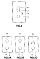
- the shape of the discharge opening 2a is not limited to a circular shape but any shape such as, for example, an ellipsoidal shape, a triangular shape or a crescent shape as shown in Figs. 3A to 3C is applicable.
- the discharge opening 2a having any of these shapes can be easily formed by varying the shape of a mask used in a laser-machining process. For example, if an intended shape of the discharge opening 2a is a circle, it can be formed by using a mask having an ellipsoidal shape.
- the opening area S2 of the discharge opening 2a of the metering nozzle 2 is preferably in the range satisfying the condition of 5/10,000 ⁇ S2/S1 ⁇ 10.
- the ratio S2/S1 of the opening area S2 to the opening area S2 exceeds 10, ink spreads over an area surrounding the discharge opening so that an accuracy for metering the ink is deteriorated.
- the ratio S2/S1 is less than 5/10,000, the amount of ink to be metered at one metering cycle becomes too small.
- the afore-mentioned opening area S2 is in the range satisfying the condition of 5/10,000 ⁇ S2/S1 ⁇ 5.
- the metering nozzle 2 and the ejecting side nozzle 1 are independently provided and the minimum distance d therebetween is limited to the afore-mentioned range, natural mixing of the transparent solvent 4 and the ink 6 in the stand-by condition can be surely prevented without provision of complicated mechanisms such as one-way valve.
- the application of voltage to the pressure-applying means provided on the metering side is interrupted, and a driving pulse is applied to another pressure-applying means provided on the ejecting side, so that the inner pressure in the ejecting nozzle 2 is lowered to a negative pressure while the inner pressure in the ejecting nozzle is raised.
- the ink 6 is separated from the fluid mixture 10 composed of the ink 6 and the transparent solvent 4 and returned into the metering nozzle 2 so that the meniscus of the ink 6 is retracted to a position inside the metering nozzle 2, as shown in Fig. 4C.
- the fluid mixture separated from the ink 6 projects outwardly from the discharge opening 1a of the ejecting nozzle 1, as shown in Fig. 4C.
- the ejecting nozzle 15 has, at one end thereof, a discharge opening 15a serving as a diluent orifice and, at the other end thereof, a supply opening 15b into which the transparent solvent 4 as a diluent is introduced through the diluent feed passage 5 in the same manner as described in the afore-mentioned Embodiment 1.
- This embodiment shows a printing device which is a combination of the end-face type having no orifice plate, and the non-premixing type having a plurality of metering nozzles.
- the afore-mentioned channel 34 is in the form of a droplet when viewed in top plan and has a relatively wide portion serving as the diluent feed passage 32 and a relatively narrow portion serving as the ejecting nozzle 33 and gradually tapered in width toward an open end thereof.
- a primary surface 71a of a base plate 71 is grooved to form a first channel 74 which defines a diluent feed passage 72 for the transparent solvent as a diluent and an ejecting nozzle 73 communicated with the diluent feed passage 72, a second channel 77 which defines a first ink feed passage 75 and a first metering nozzle 76 communicated with the first ink feed passage 75, and a third channel 80 which defines a second ink feed passage 78 and a second metering nozzle 79 communicated with the second ink passage 78.
- the first channel 74 is so arranged as to be interposed between the second and third channels 77 and 80.
- the first to third channels are covered with an oscillation plate 81 adhered onto the primary surface 71a of the base plate 71 to finally define the respective ink feed and diluent feed passages and the ejecting and metering nozzles.
- the base plate 71 is further provided, on a back surface 71b thereof opposite to the primary surface 71a, with a fourth channel 84 which defines a third ink feed passage 82 and a third metering nozzle 83 communicated with the third ink feed passage 82, and a fifth channel which defines a fourth ink feed passage 85 and a fourth metering nozzle 86 communicated with the third ink feed passage 85.
- the fourth and fifth channels 84 and 87 on the back surface 71b are disposed in an opposed relation to the second and third channel 77 and 80 on the primary surface 71a, respectively.
- an opening area S1 of the discharge opening of the ejecting nozzle 73 and an opening area S2 of the discharge opening of each of the first, second, third and fourth metering nozzles 76, 79, 83 and 86 are so determined as to satisfy the same conditions as described in the afore-mentioned Embodiment 1.
- the discharge openings of the ejecting nozzle 73 and the first, second, third and fourth metering nozzles 76, 79, 83 and 86 may have various shapes as described in the preceding embodiments, though there is some limitation due to the fact that they must be defined by the respective channels and the diaphragms 81 and 88.
Landscapes
- Physics & Mathematics (AREA)
- Geometry (AREA)
- Particle Formation And Scattering Control In Inkjet Printers (AREA)
- Ink Jet (AREA)
- Application Of Or Painting With Fluid Materials (AREA)
Abstract
Description
- This invention relates to a printing device capable of ejecting a liquid mixture composed, for example, of ink and a diluent toward a recording medium, and more particularly to an improvement in arrangement of nozzles.
- So-called on-demand-type ink jet printer is adapted to form print images on a recording medium such as paper or film by ejecting ink droplets through nozzles in response to recording signals supplied to the printer. Recently, the ink jet printer of such a on-demand type has been rapidly prevailed due to its compactness or low manufacturing cost.
- USP 5,371,529 previously filed by the present applicant, discloses the printer of such a on-demand type in which a gradation of recorded images is achieved by mixing ink and a transparent solvent as diluent at adequate proportions with each other immediately before ejection thereof. In such a printer, a concentration of the print images can be varied every recording dot, so that the printer is advantageous for obtaining a high quality duplicate of natural images such as particularly those from photographs.
- The printer is of a so-called intermixing type in which ink and diluent are mixed together in an interior of the ejection nozzle.
- Meanwhile, in the conventional intermixing type printing device, there has been a problem that natural mixing of ink and diluent and, therefore, mutual diffusion therebetween are likely to occur, because they are brought into contact with each other during a stand-by period. In order to overcome the problem, the present applicant has proposed, in the afore-mentioned USP 5,371,529 the printer in which a one-way valve manufactured according to an electro-forming method is disposed in a boundary region between ink and diluent so as to prevent occurrence of the mutual diffusion therebetween during the stand-by period.
- However, it is often difficult to completely separate ink from diluent during the stand-by period only by the arrangement of such a one-way valve. In addition, The one-way valve has another problem that its manufacturing cost is high.
- The present invention has been accomplished in view of the afore-mentioned problems.
- It is therefore an object of the present invention to provide a printing device having a simple structure and capable of preventing occurrence of natural mixing of ink and diluent during a stand-by period of an ink ejection process whereby mixing of ink and diluent and ejection of a fluid mixture composed of the ink and the diluent can be carried out surely .
- In a first aspect of the present invention, there is provided a printing device including an ejecting nozzle with a first discharge opening and a metering nozzle with a second discharge opening, which are provided separately from each other to feed two kinds of fluids through the first and second discharge openings, respectively, the two kinds of fluids being mixed together to form a fluid mixture to be ejected toward a recording medium, wherein a minimum distance d between the first and second discharge openings of the metering and ejecting nozzles is in the range of

- In a second aspect of the present invention, there is provided a printing device including an ejecting nozzle having a first discharge opening and a plurality of metering nozzles each having a second discharge opening, which are provided separately from each other to feed fluids through the first and second discharge openings, the fluids being mixed together to form a fluid mixture to be ejected toward a recording medium, wherein a minimum distance d between the first discharge opening of the ejecting nozzle and the second discharge opening of each of metering nozzles is in the range of

- These and other objects, features and advantages of the present invention will become more apparently from the following detailed description when read in conjunction with the accompanying drawings and the appended claims.
- For a better understanding of the present invention, reference is made to a detailed description to be read in conjunction with the accompanying drawings in which:
- Fig. 1 is an enlarged sectional view showing a printing device according to a first embodiment of the present invention;
- Fig. 2 is an enlarged plan view of the printing device shown in Fig. 1;
- Figs. 3A, 3B and 3C are enlarged plan views showing various modifications concerning shapes of discharge openings of ejecting and metering nozzles;
- Figs. 4A, 4B, 4C, 4D and 4E are enlarged sectional views showing a sequence of mixing and ejecting operations of the printing device according to the first embodiment of the present invention;
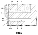
- Fig. 5 is an enlarged sectional view showing a printing device according to a second embodiment of the present invention;
- Fig. 6 is an enlarged plan view of the printing device shown in Fig. 5;
- Fig. 7 is an enlarged sectional view showing a printing device according to a third embodiment of the present invention;
- Fig. 8 is an enlarged plan view of the printing device shown in Fig. 5;
- Figs. 9A to 9C are views showing a printing device according to a fourth embodiment of the present invention; Fig. 9A is a plan view showing the condition in which a cover plate is removed therefrom, Fig. 9B is a front elevation of the printing device when viewed from a nozzle side thereof, and Fig. 9C is a vertical section of the printing device;
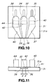
- Fig. 10 is a plan view showing a base plate of a printing device according to a fifth embodiment of the present invention;
- Fig. 11 is a front elevation of the printing device shown in Fig. 10;
- Fig. 12 is a plan view showing a base plate of a printing device according to a sixth embodiment of the present invention;
- Fig. 13 is a front elevation of the printing device shown in Fig. 12;
- Fig. 14 is a rear view of the base plate shown in Fig. 12;
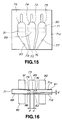
- Fig. 15 is a plan view showing a base plate of a printing device according to a seventh embodiment of the present invention;
- Fig. 16 is a front elevation of the printing device shown in Fig. 15; and
- Fig. 17 is a rear view of the base plate shown in Fig. 15;
- Preferred embodiments of a printing device according to the present invention are described in detail below by referring to the accompanying drawings. Incidentally, as will be clearly appreciated, the printing device described in the respective embodiments is provided with an ejecting nozzle and a metering nozzle separately. In the printing device according to the present invention, ink and diluent are mixed together at an exterior of the ejecting nozzle. Such a printing device is hereinafter referred to as "non-premixing-type printing device."
- In this embodiment, there is illustrated a so-called non-premixing-type printing device in which discharge openings of ejecting and metering nozzles are located in the same plane and a passage of the ejecting nozzle is inclined relative to that of the metering nozzle.
- As shown in Figs. 1 and 2, such a printing device has an orifice plate in which the ejecting
nozzle 1 and themetering nozzle 2 are separately provided. Theorifice plate 3 may be a plate-like or film-like member made of metal such as nickel or stainless steel, a ceramic material such as glass or silicon, or a plastic material such as polyimide or polyethylene terephthalete. - The ejecting
nozzle 1 provided in theorifice plate 3 is in the form of a straight through hole extending in the direction of a thickness of theorifice plate 3. The ejectingnozzle 1 is provided, at one end thereof, with a discharge opening 1a and, at the other end, with a supply opening 1b. To the supply opening 1b, atransparent solvent 4, for example, a diluent is supplied through adiluent feed passage 5. - On the other hand, the
metering nozzle 2 is also in the form of a through hole and defines a flow path inclined relative to thediluent feed passage 5 which communicates with the ejectingnozzle 1. That is, themetering nozzle 2 is provided at one end thereof with a discharge opening 2a serving as an ink orifice. The inclination of themetering nozzle 2 relative to the ejectingnozzle 1 is such that the former gradually approaches the latter from a back side of theorifice plate 3 toward a front side thereof at which thedischarge opening 2a is located. The inclined flow path of themetering nozzle 2 is formed, for example, by a laser-machining process. - In order to produce the
metering nozzle 2 inclined relative to the ejectingnozzle 1, theorifice plate 3, which is made of a polyimide film having a thickness of 50 µm, is radiated with a excimer-laser beam at an angle of 43 degrees relative to a normal line of theorifice plate 3, though the inclination angle of the metering nozzle is not particularly limited. - The
metering nozzle 2 is provided at the opposite end with a supply opening 2b to which a fluid, for example,ink 6, is supplied through an ink-feeding passage 7. - It is desirable that the discharge opening 1a of the ejecting
nozzle 1 is of a point-symmetrical shape in section from a standpoint of achieving the function to eject fluid droplets. In addition, in view of easiness in designing or production, the discharge opening 1a is preferably of a circular or square shape in section. In this embodiment, the discharge opening of a circular shape is adopted. - On the other hand, the
metering nozzle 2 has a large degree of freedom with respect to the shape of the discharge opening 2a. The shape of thedischarge opening 2a is not limited to a circular shape but any shape such as, for example, an ellipsoidal shape, a triangular shape or a crescent shape as shown in Figs. 3A to 3C is applicable. Thedischarge opening 2a having any of these shapes can be easily formed by varying the shape of a mask used in a laser-machining process. For example, if an intended shape of thedischarge opening 2a is a circle, it can be formed by using a mask having an ellipsoidal shape. - Especially, in this embodiment, in order to prevent natural mixing of the
ink 6 and the transparent solvent 4 during the stand-by period, themetering nozzle 2 and the ejectingnozzle 1 are separately disposed and a minimum distance d between the discharge opening 1a of the ejectingnozzle 1 and thedischarge opening 2a of themetering nozzle 2 is limited to the range of
nozzle 1. If the minimum distance d exceeds 5√(S1), there is possibility that a responsibility for accurately determining an amount of ink is deteriorated. - The opening area S1 of the discharge opening 1a of the ejecting
nozzle 1 is preferably in the range of 50 ≦ S1 ≦ 40,000 µm2, more preferably 100 ≦ S1 ≦ 10,000 µm2. The upper limit of the opening area S1 is determined so as to obtain print images having a minimum resolution required. For example, the minimum resolution required is 75 dpi at 40,000 µm2 and 200 dpi at about 10,000 µm2. Accordingly, when the opening area S1 exceeds 40,000µm2, print images having the minimum resolution cannot be obtained. On the other hand, when the lower limit of the opening area S1 is determined so as to assure the discharge of fluid mixture through the ejecting nozzle. When the opening area S1 is less than 50 µm2, the fluid mixture cannot be ejected through the ejecting nozzle. - The opening area S2 of the
discharge opening 2a of themetering nozzle 2 is preferably in the range satisfying the condition of 5/10,000≦S2/S1≦10. When the ratio S2/S1 of the opening area S2 to the opening area S2 exceeds 10, ink spreads over an area surrounding the discharge opening so that an accuracy for metering the ink is deteriorated. On the other hand, when the ratio S2/S1 is less than 5/10,000, the amount of ink to be metered at one metering cycle becomes too small. In addition, in order to perform the metering of ink with a high accuracy, the afore-mentioned opening area S2 is in the range satisfying the condition of 5/10,000≦S2/S1≦5. Furthermore, in order to accomplish the high-accuracy metering of ink only at one metering cycle, the ratio S2/S1 is preferably in the range of 1/100≦S2/S1≦5. When it is required to reduce a minimum concentration of dots recorded, the ratio S2/S1 is preferably in the range of 1/100≦S2/S1≦1/2. - Next, recording operation of the printing device according to the present invention is described by referring to Figs. 4A to 4E .
- When the printing device is in a stand-by condition, the
transparent solvent 4 andink 6 form ameniscus 8 at the discharge opening 1a of the ejectingnozzle 1 and ameniscus 9 at thedischarge opening 2a of themetering nozzle 2, respectively, due to a surface tension thereof, as shown in Fig. 4A. - In the printing device according to the present invention, since the
metering nozzle 2 and the ejectingside nozzle 1 are independently provided and the minimum distance d therebetween is limited to the afore-mentioned range, natural mixing of thetransparent solvent 4 and theink 6 in the stand-by condition can be surely prevented without provision of complicated mechanisms such as one-way valve. - Next, the manner that the
ink 6 metered is mixed with the transparent solvent, is explained. An inner pressure of themetering nozzle 2 is raised by operating a pressure-applying means (not shown) such as a piezo-electric element or a heating element, so that theink 6 is metered as shown in Fig. 4B. The amount of theink 6 to be mixed with thetransparent solvent 4 is varied by controlling a voltage value of voltage pulse or a pulse width impressed on the pressure-applying means. - At this time, since the flow path of the
metering nozzle 2 is inclined relative to the ejectingnozzle 1, theink 6 emerges from thedischarge opening 2a of themetering nozzle 2 toward the discharge opening 1a of the ejectingnozzle 1, so that theink 6 is allowed to be mixed with thetransparent solvent 4 due to an effect of surface tension. - Thereafter, the application of voltage to the pressure-applying means provided on the metering side is interrupted, and a driving pulse is applied to another pressure-applying means provided on the ejecting side, so that the inner pressure in the ejecting
nozzle 2 is lowered to a negative pressure while the inner pressure in the ejecting nozzle is raised. As a result, theink 6 is separated from thefluid mixture 10 composed of theink 6 and thetransparent solvent 4 and returned into themetering nozzle 2 so that the meniscus of theink 6 is retracted to a position inside themetering nozzle 2, as shown in Fig. 4C. On the other hand, the fluid mixture separated from theink 6 projects outwardly from the discharge opening 1a of the ejectingnozzle 1, as shown in Fig. 4C. - Successively, when the driving pulse applied to the pressure-applying means on the ejecting side is interrupted, the inner pressure in the ejecting
nozzle 1 is reduced to a negative pressure. As a result, as shown in Fig. 4D, thetransparent solvent 4 is retracted into an interior of the ejectingnozzle 1 so that thefluid mixture 10 having a given ink concentration is ejected in the form of droplets. - After completion of the ink ejection, as shown in Fig. 4E, the
metering nozzle 2 is charged with a fresh amount ofink 6 whereby the printer is returned to the initial stand-by condition. - This embodiment shows a printing device which is of the same non-premixing type as that of the
Embodiment 1 but in which discharge openings of ejecting and metering nozzles are not located on the same plane. - As shown in Figs. 5 and 6, such a printing device also includes an
orifice plate 13 in which an ejecting nozzle 11 and ametering nozzle 12 are provided separately from each other. The ejecting nozzle 11 is in the form of a straight through-hole and penetrates theorifice plate 13 in the thickness direction in the same manner as the afore-mentionedEmbodiment 1. - The ejecting nozzle 11 has, at one end thereof, a discharge opening 11a serving as a diluent orifice and, at the other end thereof, a supply opening 11b into which the transparent solvent 4 as a diluent is introduced through the
diluent feed passage 5. - On the other hand, the
metering nozzle 12 is provided within aprotrusion 14 projectingly formed on theorifice plate 13. Theprotrusion 14 has a rectangular shape in front elevation and projects outwardly from a plane where the discharge opening 11a of the ejecting nozzle 11 is located. Themetering nozzle 12 has such a configuration that adischarge opening 12a thereof is opened at a plane perpendicular to the plane where the discharge opening 11a of the ejecting nozzle 11 is located. This configuration makes it easier to mix theink 6 with thetransparent solvent 4. Themetering nozzle 12 further has, at the other open end, asupply opening 12b which communicates with aink feed passage 7 for supplying theink 6 to themetering nozzle 12. - Incidentally, the
orifice plate 13 may be provided thereon with multiple plated layers each made of nickel, copper or the like. - In the printing device of this embodiment, a minimum distance d between the discharge opening 11a of the ejecting nozzle 11 and the
discharge opening 12a of themetering nozzle 12 is so determined as to fall within the same range as described in the afore-mentionedEmbodiment 1. Similarly, an opening area S1 of the discharge opening 11a of the ejecting nozzle 11 and an opening area S1 of thedischarge opening 12a of themetering nozzle 12 are so determined as to satisfy the same conditions as described in the afore-mentionedEmbodiment 1. In addition, thedischarge openings 11a and 12a of the ejecting andmetering nozzles 11 and 12 can have various shapes as mentioned inEmbodiment 1. - The printing device of this embodiment can be operated in the same manner as described in
Embodiment 1. - This embodiment illustrates a printing device which is of the same non-premixing type as that of the
Embodiment 1 but in which discharge openings of ejecting and metering nozzles are not located on the same plane. In this embodiment, the metering nozzle is also arranged in an inclined relation to the ejecting nozzle. - As shown in Figs. 7 and 8, such a printing device also includes an
orifice plate 17 in which an ejectingnozzle 15 and ametering nozzle 16 are provided separately from each other. The ejectingnozzle 15 is in the form of a straight through-hole and extends through theorifice plate 17 in the direction of a thickness thereof in the same manner as the afore-mentionedEmbodiment 1. - The ejecting
nozzle 15 has, at one end thereof, adischarge opening 15a serving as a diluent orifice and, at the other end thereof, a supply opening 15b into which the transparent solvent 4 as a diluent is introduced through thediluent feed passage 5 in the same manner as described in the afore-mentionedEmbodiment 1. - On the other hand, the
metering nozzle 16 is provided in an enlarged portion of theorifice plate 17 which has a larger thickness than that of a portion where the ejectingnozzle 15 is located. Themetering nozzle 16 is also inclined toward the ejectingnozzle 15 to make it easier to mix theink 6 with thetransparent solvent 4. Adischarge opening 16a of themetering nozzle 16 is opened at aslant surface 18 provided on the enlarged portion of theorifice plate 17. Themetering nozzle 16 is provided, at the other end, asupply opening 16b which communicates with theink feed passage 7 to introduce theink 6 into themetering nozzle 16. - Incidentally, the
orifice plate 17 can be produced by subjecting a plastic sheet to a hole-forming process in which an excimer-laser is employed. - In the printing device of this embodiment, a minimum distance d between the
discharge opening 15a of the ejectingnozzle 15 and thedischarge opening 16a of themetering nozzle 16 is so determined as to fall within the same range as described in the afore-mentionedEmbodiment 1. Similarly, an opening area S1 of thedischarge opening 15a of the ejectingnozzle 15 and an opening area S2 of thedischarge opening 16a of themetering nozzle 16 are so determined as to satisfy the same conditions as described in the afore-mentionedEmbodiment 1. In addition, thedischarge openings metering nozzles Embodiment 1. - The printing device of this embodiment can be also operated in the same manner as described in
Embodiment 1. - In the afore-mentioned embodiments, there are described printing devices all having the orifice plate. However, the present invention is also applicable to printing devices having no orifice plate.
Embodiment 4 shows a so-called end-face type printing device having no orifice plate. - In the production of such a printing device, as shown in Fig. 9, a primary surface of a base 19 made of stainless steel or the like is grooved by using etching or the like methods to form two channels thereon. The thus-formed two channels serving respectively as a
metering nozzle 20 and an ejectingnozzle 21 is covered with acover plate 22 adhered onto the primary surface of thebase 19. In this case, a minimum distance between discharge openings of themetering nozzle 20 and the ejectingnozzle 21 is so determined as to satisfy the same conditions as described inEmbodiment 1. Similarly, an opening area S1 of the discharge opening of the ejectingnozzle 21 and an opening area S2 of the discharge opening of themetering nozzle 20 are so determined as to satisfy the same conditions as described in the afore-mentionedEmbodiment 1. In addition, the discharge openings of the ejecting andmetering nozzles Embodiment 1. - The printing device of this embodiment can be also operated in the same manner as described in
Embodiment 1. - This embodiment shows a printing device which is a combination of the end-face type having no orifice plate, and the non-premixing type having a plurality of metering nozzles.
- Such a printing device has substantially the same configuration as that of the printing device described in
Embodiment 4. - That is, as shown in Figs. 10 and 11, a
primary surface 31a of abase plate 31 is grooved to form afirst channel 34 which defines adiluent feed passage 32 for the transparent solvent as a diluent and an ejectingnozzle 33 communicated with thediluent feed passage 32, asecond channel 37 which defines a firstink feed passage 35 for the ink and afirst metering nozzle 36 communicated with the firstink feed passage 35, and athird channel 40 which defines a secondink feed passage 38 and asecond metering nozzle 39 communicated with the secondink feed passage 38. Thefirst channel 34 is so arranged as to be interposed between the second andthird channels diaphragm 41 adhered onto theprimary surface 31a of thebase plate 31 to finally define the respective nozzles and passages. - Accordingly, similar to the preceding embodiments, the transparent solvent as a diluent is supplied through the
diluent feed passage 32 to the ejectingnozzle 33. Whereas, the ink is supplied through the first and secondink feed passages second metering nozzles - The afore-mentioned
channel 34 is in the form of a droplet when viewed in top plan and has a relatively wide portion serving as thediluent feed passage 32 and a relatively narrow portion serving as the ejectingnozzle 33 and gradually tapered in width toward an open end thereof. - The second and
third channels nozzle 33 in order to facilitate metering and emerging of the ink and mixing of the ink with the transparent solvent. The second andthird channels ink feed passage second metering nozzle second metering nozzles second channels nozzle 33, the ejectingnozzle 33 is interposed between the first andsecond metering nozzles base plate 31. - Meanwhile, the
base plate 31 and thediaphragm 41 may be made of metal such as nickel and stainless steel, a ceramic material such as glass and silicon, or a plastic material such as polyimide and polyethylene terephthalate. The formation of the channels on theprimary surface 31a of thebase plate 31 can be performed by etching, injecting-molding or other adequate methods depending upon the kind of material used therefor. - In this embodiment, in order to prevent natural mixing of the
ink 6 and the transparent solvent 4 during the stand-by period, the first andsecond metering nozzle nozzle 33 are separately disposed and a minimum distance d between the discharge opening of the ejectingnozzle 33 and the discharge opening of the first orsecond metering nozzle aforementioned Embodiment 1. Similarly, an opening area S1 of the discharge opening of the ejectingnozzle 33 and an opening area S2 of the discharge opening of the first orsecond metering nozzle Embodiment 1. In addition, the discharge openings of the ejectingnozzle 33 and the first andsecond metering nozzles Embodiment 1. - In the printing device according to this embodiment, the
diaphragm 41 is provided, at respective positions opposed to thediluent feed passage 32 and the first and secondink feed passages electric elements - Incidentally, the printing device according to this embodiment can be operated in substantially the same manner as described in
Embodiment 1. That is, one medium supplied from the ejectingnozzle 33 is mixed with the other medium supplied from thefirst metering nozzle 36 and/or thesecond metering nozzle 39 and the resultant fluid mixture is ejected toward a recording medium such as paper. - In the printing device of this embodiment, when the first and second
ink feed passages second metering nozzles - In addition, in the printing device according to the present embodiment, when the first and second
ink feed passages second metering nozzles - Furthermore, in the printing device according to the present invention, when the first and second
ink feed passages - This embodiment shows a printing device which is also a combination of the end-face type having no orifice plate, and the non-premixing type having a plurality of metering nozzles.
- Such a printing device has substantially the same configuration as that of the printing device described in
Embodiment 5. - That is, as shown in Figs. 12 and 13, a primary surface 51a of a
base plate 51 is grooved to form afirst channel 54 which defines adiluent feed passage 52 for the transparent solvent as a diluent and an ejectingnozzle 53 communicated with thediluent feed passage 52, asecond channel 57 which defines a firstink feed passage 55 and afirst metering nozzle 56 communicated with the firstink feed passage 55, and athird channel 60 which defines a secondink feed passage 58 and asecond metering nozzle 59 communicated with thesecond ink passage 58. Thefirst channel 54 is so arranged as to be interposed between the second andthird channels oscillation plate 41 adhered onto the primary surface 51a of thebase plate 51 to finally define the respective ink feed and diluent feed passages and the ejecting and metering nozzles. - In the printing device of this embodiment, as shown in Figs. 13 and 14, the
base plate 51 is further provided, on aback surface 51b thereof opposite to the primary surface 51a, with athird channel 64 which defines a thirdink feed passage 62 and athird metering nozzle 63 communicated with the thirdink feed passage 62. Thefourth channel 64 on theback surface 51b is disposed in an opposed relation to thefirst channel 54 on the primary surface 51a. Thefourth channel 64 is covered with anoscillation plate 65 to finally define the thirdink feed passage 62 and thethird metering nozzle 63. - Similar to the preceding embodiments, in the printing device of this embodiment, the transparent solvent as a diluent is supplied through the
diluent feed passage 52 to the ejectingnozzle 53 and the ink is supplied through the first, second and thirdink feed passages third metering nozzles - The first, second and
third channels third channels Embodiment 4, respectively. Similarly, the fourth channel may be of an approximately droplet shape in top plan and has a relatively wide portion which defines the thirdink feed passage 62 and a relatively narrow portion which defines thethird metering nozzle 63. As a result, the ejectingnozzle 53 is so arranged as to be interposed between the first andsecond metering nozzles third metering nozzle 63 in the direction of a thickness of thebase plate 51. - Meanwhile, the
base plate 51 and thediaphragms Embodiment 5. The formation of the channels on the primary and back surfaces of thebase plate 51 can be also performed in the same manner as described inEmbodiment 5. - In the printing device of this embodiment, in order to prevent natural mixing of the
ink 6 and the transparent solvent 4 during the stand-by period, the first, second andthird metering nozzles nozzle 53 are separately disposed and a minimum distance d between the discharge opening of the ejectingnozzle 53 and the discharge opening of each of the first, second andthird metering nozzles Embodiment 1. Similarly, an opening area S1 of the discharge opening of the ejectingnozzle 53 and an opening area S2 of the discharge opening of each of the first, second andthird metering nozzles Embodiment 1. In addition, the discharge openings of the ejectingnozzle 53 and the first, second andthird metering nozzles - In the printing device according to this embodiment, the
diaphragm 61 is provided, at respective positions opposed to thediluent feed passage 52 and the first and secondink feed passages electric elements oscillation plate 65 is provided, on an outside surface thereof opposed to the thirdink feed passages 62, with laminate-type piezo-electric elements 69 as a pressure-applying means - Incidentally, the printing device according to this embodiment can be operated in substantially the same manner as described in
Embodiment 1. That is, one medium supplied from the ejectingnozzle 53 is mixed with the other medium supplied from at least one of the first, second andthird metering nozzles - In the printing device of this embodiment, the first, second and third
ink feed passages ink feed passages Embodiment 5. - In addition, in the printing device according to the present embodiment, if the first, second and third metering nozzles are respectively supplied with ink compositions having different color tones, e.g., yellow, magenta and cyan, fluid mixtures each composed of diluent and either one of ink compositions having different color tones can be selectively ejected from the single nozzle unit. This enables reduction in total number of nozzles and size of the printing device. In this case, when the different ink compositions are supplied from the metering nozzles at the same time, it is possible to eject the fluid mixture having various mixed color tones whereby a full-colored print images can be obtained.
- This embodiment shows a printing device which is also a combination of the end-face type having no orifice plate, and the non-premixing type having a plurality of metering nozzles.
- Such a printing device has substantially the same configuration as that of the printing device described in
Embodiment 5. - That is, as shown in Figs. 15 and 16, a
primary surface 71a of abase plate 71 is grooved to form afirst channel 74 which defines adiluent feed passage 72 for the transparent solvent as a diluent and an ejectingnozzle 73 communicated with thediluent feed passage 72, asecond channel 77 which defines a firstink feed passage 75 and afirst metering nozzle 76 communicated with the firstink feed passage 75, and athird channel 80 which defines a secondink feed passage 78 and asecond metering nozzle 79 communicated with thesecond ink passage 78. Thefirst channel 74 is so arranged as to be interposed between the second andthird channels oscillation plate 81 adhered onto theprimary surface 71a of thebase plate 71 to finally define the respective ink feed and diluent feed passages and the ejecting and metering nozzles. - In the printing device of this embodiment, as shown in Figs. 16 and 17, the
base plate 71 is further provided, on aback surface 71b thereof opposite to theprimary surface 71a, with afourth channel 84 which defines a thirdink feed passage 82 and athird metering nozzle 83 communicated with the thirdink feed passage 82, and a fifth channel which defines a fourthink feed passage 85 and afourth metering nozzle 86 communicated with the thirdink feed passage 85. The fourth andfifth channels back surface 71b are disposed in an opposed relation to the second andthird channel primary surface 71a, respectively. In addition, The fourth andfifth channels oscillation plate 88 adhered to theback surface 71b of thebase plate 71 to finally define the third and fourthink feed passage fourth metering nozzle - Similar to the preceding embodiments, in the printing device of this embodiment, the transparent solvent as a diluent is supplied through the
diluent feed passage 72 to the ejectingnozzle 73 and the ink is supplied through the first, second, third and fourthink feed passages fourth metering nozzles - The first, second and
third channels third channels Embodiment 5, respectively. The fourth andfifth channels third channels ink feed passage third metering nozzle - As a result, the ejecting
nozzle 73 is so arranged as to be interposed between the first andsecond metering nozzles second metering nozzles fourth metering nozzles base plate 71. - Meanwhile, the
base plate 71 and thediaphragms Embodiment 5. The formation of the channels on the primary and back surfaces 71a and 71 b of thebase plate 71 can be performed in the same manner as described inEmbodiment 5. - In the printing device of this embodiment, in order to prevent natural mixing of the
ink 6 and the transparent solvent 4 during the stand-by period, the first, second, third andfourth metering nozzles nozzle 73 are independently disposed and a minimum distance d between the discharge opening of the ejectingnozzle 73 and the discharge opening of each of the first, second, third andfourth metering nozzles Embodiment 1. Similarly, an opening area S1 of the discharge opening of the ejectingnozzle 73 and an opening area S2 of the discharge opening of each of the first, second, third andfourth metering nozzles Embodiment 1. In addition, the discharge openings of the ejectingnozzle 73 and the first, second, third andfourth metering nozzles diaphragms - In the printing device according to this embodiment, laminate-type piezo-
electric elements oscillation plate 81 at the respective positions corresponding to thediluent feed passage 72 and the first and secondink feed passages piezoelectric elements oscillation plate 88 at the respective positions corresponding to the third and fourthink feed passages - Incidentally, the printing device according to this embodiment can be operated in substantially the same manner as described in
Embodiment 1. That is, one medium supplied from the ejectingnozzle 73 is mixed with the other medium supplied from at least one of the first, second, third andfourth metering nozzles - In the printing device of this embodiment, the first, second, third and fourth
ink feed passages ink feed passages Embodiment 5. - In addition, in the printing device according to the present embodiment, if the first, second, third and fourth metering nozzles are respectively supplied with ink compositions having different color tones, e.g., yellow, magenta, cyan and black, various fluid mixtures, which are each composed of the diluent and either one of ink compositions having different color tones, can be selectively ejected from the single nozzle unit. This enables reduction in total number of nozzles and size of the printing device. In this case, when the different ink compositions are supplied from the metering nozzles at the same time at proper proportions, it is possible to eject the fluid mixture having various mixed color tone whereby a full-colored print images can be obtained.
- The afore-mentioned embodiments are only illustrative and therefore not intended to limit a scope of the present invention. As will be apparently understood, various changes and modifications can be made without departing from the sprits and scope of the present invention.
- For instance, in almost all of the afore-mentioned embodiments, the ejecting nozzle and the metering nozzles are so arranged that center lines of the latter intersects that of the former. However, the present invention is not restricted to such a particular arrangement. For example, the center lines of the ejecting and metering nozzles can be disposed in skewed relation or parallel to each other.
- As described above, in a printing device according to the present invention, since metering and ejecting nozzles are provided separately from each other, there is no likelihood that ink and a diluent therefor are mixed together in a stand-by condition of the printing device whereby it is surely prevented to cause natural mixing of the ink and the diluent upon ejection of the fluid mixture. In addition, This enables simplified construction of the printing device and permits stable mixing and ejecting operations of the fluid mixture composed of the ink and the diluent without complicated mechanisms such as valves, which leads to simplification of manufacturing processes and reduction in its manufacturing cost.
- Besides, in accordance with the present invention, since a minimum distance d between discharge openings of the metering and ejecting nozzles is limited to a particular range, a good metering responsibility to fluid to be metered can be obtained and improved mixing and ejecting operations for the fluid mixture composed of the ink and the diluent can be surely performed.
Claims (10)
- A printing device comprising an ejecting nozzle with a first discharge opening and a metering nozzle with a second discharge opening, which are provided separately from each other to feed two kinds of fluids through said first and second discharge openings, respectively, said two kinds of fluids being mixed together to form a fluid mixture to be ejected toward a recording medium,
wherein a minimum distance d between said first and second discharge openings of said ejecting and metering nozzles is in the range of
- The printing device as claimed in claim 1, wherein said opening area S1 of said first discharge opening of said ejecting nozzle is in the range of 50 ≦ S1 ≦ 40,000 µm.
- the printing device as claimed in claim 1, wherein said second discharge opening has an opening area S2 and the ratio of the opening area S2 to the opening area S1 is in the range of 5/10,000 ≦ S2/S1 ≦ 10.
- the printing device as claimed in claim 1, wherein said two kinds of fluids are ink and a diluent, respectively.
- A printing device comprising an ejecting nozzle having a first discharge opening and a plurality of metering nozzles each having a second discharge opening, which are provided separately from each other to feed fluids through said first and second discharge openings, said fluids being mixed together to form a fluid mixture to be ejected toward a recording medium,
wherein a minimum distance d between said first discharge opening of said ejecting nozzle and said second discharge opening of each of said plurality of metering nozzles is in the range of
- The printing device as claimed in claim 5, wherein said opening area S1 of said first discharge opening of said ejecting nozzle is in the range of 50 ≦ S1 ≦ 40,000 µm.
- The printing device as claimed in claim 5, wherein said second discharge opening has an opening area S2 and the ratio of the opening area S2 to the opening area S1 is in the range of 5/10,000 ≦ S2/S1 ≦ 10.
- The printing device as claimed in claim 5, wherein said ejecting nozzle is adapted to supply a diluent and said plurality of metering nozzles are adapted to supply different ink compositions which are the same in color tone and different in concentration from each other.
- The printing device as claimed in claim 5, wherein said ejecting nozzle is adapted to supply a diluent and said plurality of metering nozzles are adapted to supply different ink compositions which are different in color tone from each other.
- The printing device as claimed in claim 5, wherein said ejecting nozzle is adapted to supply a diluent and said plurality of metering nozzles are adapted to supply ink compositions which are the same in both color tone and concentration.
Applications Claiming Priority (2)
| Application Number | Priority Date | Filing Date | Title |
|---|---|---|---|
| JP88999/95 | 1995-04-14 | ||
| JP8899995 | 1995-04-14 |
Publications (2)
| Publication Number | Publication Date |
|---|---|
| EP0737585A1 true EP0737585A1 (en) | 1996-10-16 |
| EP0737585B1 EP0737585B1 (en) | 1999-01-13 |
Family
ID=13958509
Family Applications (1)
| Application Number | Title | Priority Date | Filing Date |
|---|---|---|---|
| EP96105732A Expired - Lifetime EP0737585B1 (en) | 1995-04-14 | 1996-04-11 | Printing device |
Country Status (4)
| Country | Link |
|---|---|
| EP (1) | EP0737585B1 (en) |
| KR (1) | KR960037289A (en) |
| CN (1) | CN1142855C (en) |
| DE (1) | DE69601318T2 (en) |
Cited By (10)
| Publication number | Priority date | Publication date | Assignee | Title |
|---|---|---|---|---|
| EP0835759A1 (en) * | 1996-10-14 | 1998-04-15 | Sony Corporation | Printer |
| EP0895864A3 (en) * | 1997-07-31 | 1999-09-15 | Canon Kabushiki Kaisha | Liquid discharge method and liquid jet apparatus |
| EP1078761A3 (en) * | 1999-08-27 | 2001-06-06 | Océ-Technologies B.V. | Channel structure for an ink jet printhead |
| EP1274551A2 (en) * | 2000-03-13 | 2003-01-15 | Objet Geometries Ltd. | Compositions and methods for use in three dimensional model printing |
| US6676248B1 (en) | 1999-08-27 | 2004-01-13 | Oce-Technologies B.V. | Channel structure for an ink jet printhead |
| EP1622774A2 (en) * | 2003-04-10 | 2006-02-08 | Massachusetts Institute Of Technology | Positive pressure drop-on-demand printing |
| US7183335B2 (en) | 2000-03-13 | 2007-02-27 | Objet Geometries Ltd. | Compositions and methods for use in three dimensional model printing |
| GB2438180A (en) * | 2006-05-16 | 2007-11-21 | Cametrics Ltd | Ink jet printing methods |
| US7300619B2 (en) | 2000-03-13 | 2007-11-27 | Objet Geometries Ltd. | Compositions and methods for use in three dimensional model printing |
| WO2008074589A1 (en) * | 2006-12-21 | 2008-06-26 | Agfa Graphics Nv | Inkjet printing methods and inkjet ink sets |
Families Citing this family (6)
| Publication number | Priority date | Publication date | Assignee | Title |
|---|---|---|---|---|
| US8481241B2 (en) | 2000-03-13 | 2013-07-09 | Stratasys Ltd. | Compositions and methods for use in three dimensional model printing |
| DE10224128A1 (en) * | 2002-05-29 | 2003-12-18 | Schmid Rhyner Ag Adliswil | Method of applying coatings to surfaces |
| JP4298697B2 (en) * | 2005-11-25 | 2009-07-22 | キヤノン株式会社 | Ink jet recording head, ink jet cartridge including ink jet recording head, and ink jet recording apparatus |
| EP2155494A4 (en) * | 2007-06-14 | 2010-08-11 | Massachusetts Inst Technology | Method and apparatus for controlling film deposition |
| US20190118534A1 (en) * | 2017-10-24 | 2019-04-25 | Toshiba Tec Kabushiki Kaisha | Fluid ejection head and fluid ejection apparatus |
| US11033924B2 (en) * | 2018-01-31 | 2021-06-15 | Universal Display Corporation | Organic vapor jet print head with orthogonal delivery and exhaust channels |
Citations (4)
| Publication number | Priority date | Publication date | Assignee | Title |
|---|---|---|---|---|
| US4017869A (en) * | 1974-07-13 | 1977-04-12 | Agfa-Gevaert, A.G. | Ink recorder for the jet-ink-process |
| DE3501905A1 (en) * | 1983-08-01 | 1985-12-12 | Veb Kombinat Robotron, Ddr 8012 Dresden | Method of colour recording of information by means of ink jet |
| US4614953A (en) * | 1984-04-12 | 1986-09-30 | The Laitram Corporation | Solvent and multiple color ink mixing system in an ink jet |
| EP0538147A2 (en) * | 1991-10-17 | 1993-04-21 | Sony Corporation | Ink-jet print head and ink-jet printer |
-
1996
- 1996-04-11 DE DE69601318T patent/DE69601318T2/en not_active Expired - Fee Related
- 1996-04-11 EP EP96105732A patent/EP0737585B1/en not_active Expired - Lifetime
- 1996-04-12 CN CNB961103353A patent/CN1142855C/en not_active Expired - Fee Related
- 1996-04-13 KR KR1019960011109A patent/KR960037289A/en not_active Application Discontinuation
Patent Citations (4)
| Publication number | Priority date | Publication date | Assignee | Title |
|---|---|---|---|---|
| US4017869A (en) * | 1974-07-13 | 1977-04-12 | Agfa-Gevaert, A.G. | Ink recorder for the jet-ink-process |
| DE3501905A1 (en) * | 1983-08-01 | 1985-12-12 | Veb Kombinat Robotron, Ddr 8012 Dresden | Method of colour recording of information by means of ink jet |
| US4614953A (en) * | 1984-04-12 | 1986-09-30 | The Laitram Corporation | Solvent and multiple color ink mixing system in an ink jet |
| EP0538147A2 (en) * | 1991-10-17 | 1993-04-21 | Sony Corporation | Ink-jet print head and ink-jet printer |
Cited By (21)
| Publication number | Priority date | Publication date | Assignee | Title |
|---|---|---|---|---|
| US6139134A (en) * | 1996-10-14 | 2000-10-31 | Sony Corporation | Printer |
| US6312120B1 (en) | 1996-10-14 | 2001-11-06 | Sony Corporation | Printer |
| EP0835759A1 (en) * | 1996-10-14 | 1998-04-15 | Sony Corporation | Printer |
| EP0895864A3 (en) * | 1997-07-31 | 1999-09-15 | Canon Kabushiki Kaisha | Liquid discharge method and liquid jet apparatus |
| US6164748A (en) * | 1997-07-31 | 2000-12-26 | Canon Kabushiki Kaisha | Liquid discharge method and liquid jet apparatus |
| US6676248B1 (en) | 1999-08-27 | 2004-01-13 | Oce-Technologies B.V. | Channel structure for an ink jet printhead |
| EP1078761A3 (en) * | 1999-08-27 | 2001-06-06 | Océ-Technologies B.V. | Channel structure for an ink jet printhead |
| US7183335B2 (en) | 2000-03-13 | 2007-02-27 | Objet Geometries Ltd. | Compositions and methods for use in three dimensional model printing |
| US8106107B2 (en) | 2000-03-13 | 2012-01-31 | Objet Geometries Ltd. | Compositions and methods for use in three dimensional model printing |
| US9744720B2 (en) | 2000-03-13 | 2017-08-29 | Stratasys Ltd. | Methods for three dimensional model printing |
| EP1274551A2 (en) * | 2000-03-13 | 2003-01-15 | Objet Geometries Ltd. | Compositions and methods for use in three dimensional model printing |
| EP1274551A4 (en) * | 2000-03-13 | 2003-06-11 | Objet Geometries Ltd | Compositions and methods for use in three dimensional model printing |
| US7300619B2 (en) | 2000-03-13 | 2007-11-27 | Objet Geometries Ltd. | Compositions and methods for use in three dimensional model printing |
| US7851122B2 (en) | 2000-03-13 | 2010-12-14 | Objet Geometries Ltd. | Compositions and methods for use in three dimensional model printing |
| US7479510B2 (en) | 2000-03-13 | 2009-01-20 | Objet Geometries Ltd. | Compositions and methods for use in three dimensional model printing |
| EP1622774A4 (en) * | 2003-04-10 | 2009-07-15 | Massachusetts Inst Technology | Positive pressure drop-on-demand printing |
| EP1622774A2 (en) * | 2003-04-10 | 2006-02-08 | Massachusetts Institute Of Technology | Positive pressure drop-on-demand printing |
| GB2438180A (en) * | 2006-05-16 | 2007-11-21 | Cametrics Ltd | Ink jet printing methods |
| WO2008074589A1 (en) * | 2006-12-21 | 2008-06-26 | Agfa Graphics Nv | Inkjet printing methods and inkjet ink sets |
| US8282197B2 (en) | 2006-12-21 | 2012-10-09 | Agfa Graphics Nv | Inkjet printing methods and inkjet ink sets |
| AU2007334792B2 (en) * | 2006-12-21 | 2012-11-15 | Agfa Nv | Inkjet printing methods and inkjet ink sets |
Also Published As
| Publication number | Publication date |
|---|---|
| EP0737585B1 (en) | 1999-01-13 |
| CN1140660A (en) | 1997-01-22 |
| DE69601318D1 (en) | 1999-02-25 |
| CN1142855C (en) | 2004-03-24 |
| KR960037289A (en) | 1996-11-19 |
| DE69601318T2 (en) | 1999-08-26 |
Similar Documents
| Publication | Publication Date | Title |
|---|---|---|
| US6086196A (en) | Printing device | |
| EP0737585B1 (en) | Printing device | |
| EP0787588B1 (en) | Print head and method for controlling the spread of fluid around a nozzle orifice | |
| US6474799B1 (en) | Ink cartridge and a printing device using the ink cartridge | |
| KR100242804B1 (en) | Ink jet print head and ink jet printer | |
| US7300137B2 (en) | Liquid-discharge recording head | |
| US6149257A (en) | Ink-jet printing apparatus capable of increased image uniformity | |
| JPH05201003A (en) | Roof shooter type thermal ink jet printing head | |
| US5606351A (en) | Altering the intensity of the color of ink jet droplets | |
| EP0835759B1 (en) | Printer | |
| US6234613B1 (en) | Apparatus for generating small volume, high velocity ink droplets in an inkjet printer | |
| EP1108549B1 (en) | Continuous color ink jet print head apparatus and method | |
| US6932462B2 (en) | Ink jet head and ink jet recording apparatus | |
| JP2602027Y2 (en) | Stackable droplet generator for inkjet printers | |
| JP3331976B2 (en) | ink cartridge | |
| US6443551B1 (en) | Method and apparatus for forming image using image forming liquid enveloped in image non-forming liquid | |
| US6158842A (en) | Printer apparatus | |
| US5980014A (en) | Print head providing controlled mixing of ink and diluent on the surface of the print head prior to ejectment | |
| US6179410B1 (en) | Printer | |
| JPH10264372A (en) | Ink-jet head | |
| JPH08336990A (en) | Printer | |
| US6042209A (en) | Microfluidic printing with optical density control | |
| JP2000211145A (en) | Ink jet recording head and manufacture thereof | |
| JP2000043296A (en) | Printer | |
| KR100234607B1 (en) | Driving method of printer apparatus |
Legal Events
| Date | Code | Title | Description |
|---|---|---|---|
| PUAI | Public reference made under article 153(3) epc to a published international application that has entered the european phase |
Free format text: ORIGINAL CODE: 0009012 |
|
| AK | Designated contracting states |
Kind code of ref document: A1 Designated state(s): DE FR GB |
|
| 17P | Request for examination filed |
Effective date: 19970319 |
|
| GRAG | Despatch of communication of intention to grant |
Free format text: ORIGINAL CODE: EPIDOS AGRA |
|
| 17Q | First examination report despatched |
Effective date: 19980316 |
|
| GRAG | Despatch of communication of intention to grant |
Free format text: ORIGINAL CODE: EPIDOS AGRA |
|
| GRAH | Despatch of communication of intention to grant a patent |
Free format text: ORIGINAL CODE: EPIDOS IGRA |
|
| GRAH | Despatch of communication of intention to grant a patent |
Free format text: ORIGINAL CODE: EPIDOS IGRA |
|
| GRAA | (expected) grant |
Free format text: ORIGINAL CODE: 0009210 |
|
| AK | Designated contracting states |
Kind code of ref document: B1 Designated state(s): DE FR GB |
|
| REF | Corresponds to: |
Ref document number: 69601318 Country of ref document: DE Date of ref document: 19990225 |
|
| ET | Fr: translation filed | ||
| PLBE | No opposition filed within time limit |
Free format text: ORIGINAL CODE: 0009261 |
|
| STAA | Information on the status of an ep patent application or granted ep patent |
Free format text: STATUS: NO OPPOSITION FILED WITHIN TIME LIMIT |
|
| 26N | No opposition filed | ||
| REG | Reference to a national code |
Ref country code: GB Ref legal event code: IF02 |
|
| PGFP | Annual fee paid to national office [announced via postgrant information from national office to epo] |
Ref country code: GB Payment date: 20050406 Year of fee payment: 10 |
|
| PGFP | Annual fee paid to national office [announced via postgrant information from national office to epo] |
Ref country code: DE Payment date: 20050407 Year of fee payment: 10 |
|
| PGFP | Annual fee paid to national office [announced via postgrant information from national office to epo] |
Ref country code: FR Payment date: 20050408 Year of fee payment: 10 |
|
| PG25 | Lapsed in a contracting state [announced via postgrant information from national office to epo] |
Ref country code: GB Free format text: LAPSE BECAUSE OF NON-PAYMENT OF DUE FEES Effective date: 20060411 |
|
| PG25 | Lapsed in a contracting state [announced via postgrant information from national office to epo] |
Ref country code: DE Free format text: LAPSE BECAUSE OF NON-PAYMENT OF DUE FEES Effective date: 20061101 |
|
| GBPC | Gb: european patent ceased through non-payment of renewal fee |
Effective date: 20060411 |
|
| REG | Reference to a national code |
Ref country code: FR Ref legal event code: ST Effective date: 20061230 |
|
| PG25 | Lapsed in a contracting state [announced via postgrant information from national office to epo] |
Ref country code: FR Free format text: LAPSE BECAUSE OF NON-PAYMENT OF DUE FEES Effective date: 20060502 |