EP0736936B1 - Shielded connector having a shell which can be mechanically coupled to a mating connector without increasing a width of the connector - Google Patents
Shielded connector having a shell which can be mechanically coupled to a mating connector without increasing a width of the connector Download PDFInfo
- Publication number
- EP0736936B1 EP0736936B1 EP96105433A EP96105433A EP0736936B1 EP 0736936 B1 EP0736936 B1 EP 0736936B1 EP 96105433 A EP96105433 A EP 96105433A EP 96105433 A EP96105433 A EP 96105433A EP 0736936 B1 EP0736936 B1 EP 0736936B1
- Authority
- EP
- European Patent Office
- Prior art keywords
- connector
- shell
- insulator
- shielded connector
- shielded
- Prior art date
- Legal status (The legal status is an assumption and is not a legal conclusion. Google has not performed a legal analysis and makes no representation as to the accuracy of the status listed.)
- Expired - Lifetime
Links
Images


Classifications
-
- H—ELECTRICITY
- H01—ELECTRIC ELEMENTS
- H01R—ELECTRICALLY-CONDUCTIVE CONNECTIONS; STRUCTURAL ASSOCIATIONS OF A PLURALITY OF MUTUALLY-INSULATED ELECTRICAL CONNECTING ELEMENTS; COUPLING DEVICES; CURRENT COLLECTORS
- H01R13/00—Details of coupling devices of the kinds covered by groups H01R12/70 or H01R24/00 - H01R33/00
- H01R13/46—Bases; Cases
- H01R13/502—Bases; Cases composed of different pieces
- H01R13/508—Bases; Cases composed of different pieces assembled by a separate clip or spring
-
- H—ELECTRICITY
- H01—ELECTRIC ELEMENTS
- H01R—ELECTRICALLY-CONDUCTIVE CONNECTIONS; STRUCTURAL ASSOCIATIONS OF A PLURALITY OF MUTUALLY-INSULATED ELECTRICAL CONNECTING ELEMENTS; COUPLING DEVICES; CURRENT COLLECTORS
- H01R13/00—Details of coupling devices of the kinds covered by groups H01R12/70 or H01R24/00 - H01R33/00
- H01R13/648—Protective earth or shield arrangements on coupling devices, e.g. anti-static shielding
- H01R13/658—High frequency shielding arrangements, e.g. against EMI [Electro-Magnetic Interference] or EMP [Electro-Magnetic Pulse]
- H01R13/6581—Shield structure
- H01R13/6582—Shield structure with resilient means for engaging mating connector
Definitions
- This invention relates to a connector which is for use in connecting a cable with another cable or an electrical or electronic apparatus and is connected to a mating connector in a predetermined direction which will be called hereafter a first direction.
- a cable of a shield type is known and will be called hereafter a shielded cable.
- a connector of a shield type which will be called hereinafter a shielded connector.
- a conventional shielded connector comprises an insulator, a plurality of contact members, and a shell.
- the contact members have conductivity and are held to the insulator to be arranged in a second direction or a width direction perpendicular to the first direction.
- the shell is made of a metal plate and held to the insulator to electromagnetically shield the contact members.
- the conventional shielded connector is provided with a locking structure which is for being mechanically coupled or locked to the mating connector in the first direction when the shielded connector is connected to the mating connector.
- the locking structure is broadly divided into a first and a second type.
- the locking structure is formed as a separate body separate from a shell.
- the locking structure is formed as an integral body integral with the shell.
- the number of parts is increased because the shell and the locking structure are separate components. Furthermore, it is necessary to carry out a particular process of assembling the locking structure.
- the locking structure of the second type In the locking structure of the second type, no such process of assembling the locking structure is required. However, the size of the shielded connector increases in the second direction. This is because the locking structure of the second type has two movable members which are moved in the second direction at a time when connection or disconnection is carried out between the connectors.
- the first conventional shielded connector is for being connected to a mating connector (not shown) in a first direction.
- the first conventional shielded connector includes an insulator, a plurality of contact members having conductivity and held to the insulator to be arranged in a second direction perpendicular to the first direction, and a shell made of a metal plate and held to the insulator.
- the first conventional shielded connector further comprises a hood 11 made of insulating material and covers the shell and a lock spring 13 formed as a separate body separate from the shell.
- the hood 11 has an upper wall 15 and a holding portion 17 formed thereon.
- the holding portion 17 has a holding hole 19 extending parallel to the upper wall 15.
- the lock spring 13 has a locking portion 21, a spring portion 23, and a pair of hooks 25.
- the locking portion 21 is inserted into the holding hole 19 of the holding portion 17 to be tightly held therein.
- the hooks 25 are for being brought in engagement with locking holes of the mating connector in the first direction with elastic bending of the spring portion 23 when the first conventional shielded connector is connected to the mating connector.
- the upper wall 15 of the hood 11 is provided with two holding portions 27.
- Each of the holding portions 27 has a socket groove 29 extending perpendicular to the upper wall 15.
- the lock spring 13 has an upstanding locking portion 31 in addition to the spring portion 23 and the hook 25.
- the upstanding locking portion 31 is formed at a rear end of the lock spring 13 to be inserted into the socket grooves 29.
- the lock spring 13 is attached to the hood 11.
- Each of the first and the second conventional shielded connector makes the number of parts be increased because the shell and the lock spring 13 are separate components. Furthermore, this structure requires a process of assembling and fixing the lock spring 13 to the hood 11.
- a shell 33 has a shell body 35 and a pair of movable members 37 integrally connected to the shell body 35 at approximate centers of opposite side surfaces of the shell body 35.
- the movable members 37 are urged outwardly.
- the shell 33 is covered with a hood 38.
- each of reference numerals 39 represents a hook which is for being engaged with each of locking holes of a mating connector which is not illustrated in the figures.
- the shielded connector is for being electrically connected to a mating connector in a first direction.
- the mating connector is represented by a reference numeral 40 in Fig. 9 and comprises a peripheral wall 40a of metal defining a receiving hole 40b and having a pair of locking holes 40c.
- the shielded connector comprises a front shell 41, an insulator 43, a back shell 45, and a hood 47.
- the insulator 43 is made of plastic material and fixedly holds a plurality of contact members 49 only one of which is illustrated in Fig. 6.
- the contact members 49 have conductivity and are arranged at a predetermined pitch in a second direction or a width direction which is perpendicular to the first direction.
- Each of the contact members 49 has a connection portion 49a electrically connected to a cable 50 between the front and the back shells 41 and 45.
- the front shell 41 is made of a metal plate and comprises a shielding portion 51 and a lock spring or a coupling portion 53 formed integral with the shielding portion 51.
- the shielding portion 51 is for covering the insulator 43 to electromagnetically shield the contact members 49 and has a principal portion 55 extending in the first and the second directions.
- the coupling portion 53 is for being mechanically coupled to or locked up by the mating connector 40 in the first direction and comprises a spring portion 57 and an engaging portion 59.
- the spring portion 57 extends from the principal portion 55 in the first direction with gaps 58 between the spring portion 57 and the principal portion 55 to have a spring-extended end.
- the spring portion 57 is elastically bendable in a first plane extending in the first direction and a third direction or a thickness direction which is perpendicular to the first and the second directions.
- the engaging portion 59 is formed integral with the spring-extended end for being brought in engagement with the mating connector 40 in the first direction in the manner which will later be described.
- the engaging portion 59 comprises a pair of arm portions 61, a pair of hook portions 63, and a pair of engaging nails 65.
- the arm portions 61 extend opposite to each other from the spring-extended end in the second direction to have arm-extended ends.
- the hook portions 63 extend from the arm-extended ends in the first direction, respectively.
- the engaging nails 65 protrude from the hook portions 63 in the third direction and are for being inserted in the locking holes 40c of the mating connector 40 in the manner which will later be described.
- Each of the engaging nails 65 has a slant face 66 which is slanting to the first and the third directions.
- the shielding portion 51 further comprises a pair of side portions 67 extending in parallel to the first plane that is perpendicular to the principal portion 55.
- Each of the side portions 67 has an engaging hole 67a.
- a protrusion 69 is formed in the vicinity of the main extended end of the spring portion 57.
- the insulator 43 comprises an insulator body 71 and a fitting portion 73 which is formed integral with the insulator body 71 and is for being fitted into the mating connector.
- the fitting portion 73 is provided with a pair of grooves 75 in the vicinity of side surfaces of the insulator 43 in the second direction.
- Each of the grooves 75 extends in the first direction and is for receiving each of the hook portions 63 of the front shell 41. When received in the grooves 75, the hook portions 63 are prevented from movement thereof in the second direction.
- First and second locking protrusions 77 and 79 are formed on each of the side surfaces of the insulator 43.
- the first locking protrusion 77 is for being inserted in the engaging hole 67a of the front shell 41 to be engaged with each of the side portions 67 when the front shell 41 is attached to the insulator 43.
- the second locking protrusion 79 has operation which will later become clear.
- the back shell 45 is formed independent of the front shell 41 from a metal plate and coupled to the insulator 43 to electromagnetically shield the contact members 49 in cooperation with the front shell 41.
- the back shell 45 will be referred to as a shielding member.
- the back shell 45 comprises a principal portion 81 covering the insulator body 71, a projecting portion 83 covering the fitting portion 73, and a pair of side surface portions 85 covering the side surfaces of the insulator body 71.
- Each of the side surface portions 85 has an engaging hole 85a which is for receiving the second locking protrusion 79. When the engaging hole 85a receives the second locking protrusion 79, each of the side surface portions 85 is engaged with the second locking protrusion 79 in the first and the third directions.
- the front shell 41 is provided with a plurality of side walls 87 which is perpendicular to the principal portion 55 of the front shell 41.
- the back shell 45 is provided with a plurality of side walls 88 perpendicular to the principal portion 81 of the back shell 45.
- the side walls 87 and 88 serve to electromagnetically shield the contact members 49.
- the back shell 45 is attached to the insulator 43 to be brought into tight contact with the rear surface of the insulator 43.
- the front shell 41 is assembled on the insulator 43.
- the hook portions 63 of the coupling portion 53 are received in the grooves 75 with the engaging nails 65 protruding from the grooves 75.
- the grooves 75 have bottoms which are apart from the hook portions 63, respectively. In other words, a particular gap 89 is left between each of the hook portions 63 and each of the bottoms of the grooves 75.
- the hood 47 is attached to cover the front and the back shells 41 and 45.
- the shielded connector is completed.
- the hood 47 is made of plastic material and has an elastic portion 47a which is in contact with the protrusion 69 and is elastically bendable in the first plane.
- the shielded connector is represented by a reference numeral 90 and is disconnected from the mating connector 40.
- the engaging nails 65 are protruded from the grooves 75 with the particular gap 89 left therebetween.
- the fitting portion 73 is inserted into the receiving hole 40b.
- the slant face 66 is brought in press contact with an end portion of the peripheral wall 40a. This results in pushing the engaging nails 65 into the grooves 75. Therefore, the shielded connector 90 can be connected to the mating connector 40 with the fitting portion 73 inserted into the receiving hole 40b.
- the shielded connector 90 When the shielded connector 90 is connected to the mating connector 40 as illustrated in Fig. 10B, the engaging nails 65 are inserted in the locking holes 40b to be engaged with the peripheral wall 40a of the mating connector 40 in the first direction. As a result, the shielded connector 90 is mechanically connected to or tightly locked up by the mating connector 40. In this event, it is a matter of course that the contact members 49 of the shielded connector 90 are brought in contact with contact members 40d of the mating connector 40.
- the elastic portion 47a is pushed towards the protrusion 69 as depicted by an arrow mark 91 in Fig. 10B. This results in bending of the spring portion 57 to make the engaging nails 65 become out of the locking holes 40c. Therefore, the shielded connector 90 can readily be disconnected from the mating connector 40 by applying opposite force therebetween. This is because the engaging nails 65 are not engaged with the peripheral wall 40a of the mating connector 40 in the first direction.
- the shielded connector can be designed to have a size which is relatively small in the second direction so as to achieve miniaturization of the connector.
- the coupling portion 53 is formed integral with the shielding portion 51, so that the number of parts is reduced and that manufacture is easy. It is therefore possible to reduce the cost.
- the engaging portion may comprise three or more engaging nails.
Description
- This invention relates to a connector which is for use in connecting a cable with another cable or an electrical or electronic apparatus and is connected to a mating connector in a predetermined direction which will be called hereafter a first direction.
- A cable of a shield type is known and will be called hereafter a shielded cable. In connection of the shielded cable, it is preferable to use a connector of a shield type which will be called hereinafter a shielded connector.
- In the manner which will presently be described, a conventional shielded connector comprises an insulator, a plurality of contact members, and a shell. The contact members have conductivity and are held to the insulator to be arranged in a second direction or a width direction perpendicular to the first direction. The shell is made of a metal plate and held to the insulator to electromagnetically shield the contact members.
- Furthermore, the conventional shielded connector is provided with a locking structure which is for being mechanically coupled or locked to the mating connector in the first direction when the shielded connector is connected to the mating connector. In the manner which will later be described in detail in conjunction with the drawing, the locking structure is broadly divided into a first and a second type. In the first type, the locking structure is formed as a separate body separate from a shell. In the second type, the locking structure is formed as an integral body integral with the shell.
- In the locking structure of the first type, the number of parts is increased because the shell and the locking structure are separate components. Furthermore, it is necessary to carry out a particular process of assembling the locking structure.
- In the locking structure of the second type, no such process of assembling the locking structure is required. However, the size of the shielded connector increases in the second direction. This is because the locking structure of the second type has two movable members which are moved in the second direction at a time when connection or disconnection is carried out between the connectors.
- In addition, from EP 0 600 120 A1 a shielded connector for being connected to a mating connector according to the preamble of claim 1 is known.
- It is therefore an object of this invention to provide a shielded connector which is capable of reducing the number of parts and achieving miniaturization of the connector.
- Such an object is solved by a shielded connector having the features of the independent claim 1.
- Preferred developments of the invention are given in the dependent claims.
-
- Fig. 1 is a perspective view for describing a first conventional shielded connector;
- Fig. 2 is a perspective view for describing a second conventional shielded connector;
- Fig. 3 is a front view of a third conventional shielded connector having a shield case;
- Fig. 4 is a front view of the shielded connector illustrated in Fig. 2, in which the shield case is removed;
- Fig. 5A is a front view of a shielded connector according to an embodiment of this invention;
- Fig. 5B is a side view of the shielded connector of Fig. 5A;
- Fig. 5C is a a partially cut-away rear view of the shielded connector of Fig. 5A;
- Fig. 6 is a sectional view taken along a line VI-VI in Fig. 5A;
- Fig. 7 is a sectional view taken along a line VII-VII in Fig. 5A;
- Fig. 8 is an exploded perspective view of a main portion of the shielded connector illustrated in Figs. 5A through 5C;
- Fig. 9 is a perspective view of a mating connector which is connected to the shielded connector illustrated in Figs. 5A through 5C;
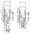
- Fig. 10A is a sectional view of a condition where the shielded connector of Figs. 5A through 5C is disconnected from the mating connector of Fig. 9; and
- Fig. 10B is a sectional view of a condition where the shielded connector of Figs. 5A through 5C is connected to the mating connector of Fig. 9.
-
- At first, description will be made as regards various conventional shielded connectors for a better understanding of this invention.
- Referring to Fig. 1, a first conventional shielded connector will be described. The first conventional shielded connector is for being connected to a mating connector (not shown) in a first direction. Although omission is carried out from Fig. 1, it is a matter of course that the first conventional shielded connector includes an insulator, a plurality of contact members having conductivity and held to the insulator to be arranged in a second direction perpendicular to the first direction, and a shell made of a metal plate and held to the insulator.
- The first conventional shielded connector further comprises a hood 11 made of insulating material and covers the shell and a
lock spring 13 formed as a separate body separate from the shell. The hood 11 has anupper wall 15 and aholding portion 17 formed thereon. Theholding portion 17 has aholding hole 19 extending parallel to theupper wall 15. On the other hand, thelock spring 13 has alocking portion 21, aspring portion 23, and a pair ofhooks 25. Thelocking portion 21 is inserted into theholding hole 19 of theholding portion 17 to be tightly held therein. Thehooks 25 are for being brought in engagement with locking holes of the mating connector in the first direction with elastic bending of thespring portion 23 when the first conventional shielded connector is connected to the mating connector. - Referring to Fig. 2, the description will be directed to a second conventional shielded connector. Similar parts are designated by like reference numerals.
- In the second conventional shielded connector, the
upper wall 15 of the hood 11 is provided with twoholding portions 27. Each of theholding portions 27 has asocket groove 29 extending perpendicular to theupper wall 15. On the other hand, thelock spring 13 has anupstanding locking portion 31 in addition to thespring portion 23 and thehook 25. Theupstanding locking portion 31 is formed at a rear end of thelock spring 13 to be inserted into thesocket grooves 29. Thus, thelock spring 13 is attached to the hood 11. - Each of the first and the second conventional shielded connector makes the number of parts be increased because the shell and the
lock spring 13 are separate components. Furthermore, this structure requires a process of assembling and fixing thelock spring 13 to the hood 11. - Referring to Figs. 3 and 4, the description will be directed to a third conventional shielded connector. In the third conventional shielded connector, a
shell 33 has ashell body 35 and a pair ofmovable members 37 integrally connected to theshell body 35 at approximate centers of opposite side surfaces of theshell body 35. Themovable members 37 are urged outwardly. Theshell 33 is covered with ahood 38. In Figs. 3 and 4, each ofreference numerals 39 represents a hook which is for being engaged with each of locking holes of a mating connector which is not illustrated in the figures. - Referring to Figs. 5A, 5B, 5C, 6, 7, and 8, the description will be made as regards a shielded connector according to an embodiment of this invention. The shielded connector is for being electrically connected to a mating connector in a first direction. The mating connector is represented by a
reference numeral 40 in Fig. 9 and comprises aperipheral wall 40a of metal defining a receivinghole 40b and having a pair of lockingholes 40c. - In the manner which will presently be described, the shielded connector comprises a
front shell 41, aninsulator 43, aback shell 45, and ahood 47. Theinsulator 43 is made of plastic material and fixedly holds a plurality ofcontact members 49 only one of which is illustrated in Fig. 6. Thecontact members 49 have conductivity and are arranged at a predetermined pitch in a second direction or a width direction which is perpendicular to the first direction. Each of thecontact members 49 has aconnection portion 49a electrically connected to acable 50 between the front and theback shells - The
front shell 41 is made of a metal plate and comprises a shieldingportion 51 and a lock spring or acoupling portion 53 formed integral with the shieldingportion 51. The shieldingportion 51 is for covering theinsulator 43 to electromagnetically shield thecontact members 49 and has aprincipal portion 55 extending in the first and the second directions. Thecoupling portion 53 is for being mechanically coupled to or locked up by themating connector 40 in the first direction and comprises aspring portion 57 and an engagingportion 59. Thespring portion 57 extends from theprincipal portion 55 in the first direction withgaps 58 between thespring portion 57 and theprincipal portion 55 to have a spring-extended end. Thespring portion 57 is elastically bendable in a first plane extending in the first direction and a third direction or a thickness direction which is perpendicular to the first and the second directions. The engagingportion 59 is formed integral with the spring-extended end for being brought in engagement with themating connector 40 in the first direction in the manner which will later be described. - The engaging
portion 59 comprises a pair ofarm portions 61, a pair ofhook portions 63, and a pair of engagingnails 65. Thearm portions 61 extend opposite to each other from the spring-extended end in the second direction to have arm-extended ends. Thehook portions 63 extend from the arm-extended ends in the first direction, respectively. The engagingnails 65 protrude from thehook portions 63 in the third direction and are for being inserted in the locking holes 40c of themating connector 40 in the manner which will later be described. Each of the engagingnails 65 has aslant face 66 which is slanting to the first and the third directions. - The shielding
portion 51 further comprises a pair ofside portions 67 extending in parallel to the first plane that is perpendicular to theprincipal portion 55. Each of theside portions 67 has anengaging hole 67a. Aprotrusion 69 is formed in the vicinity of the main extended end of thespring portion 57. - The
insulator 43 comprises aninsulator body 71 and afitting portion 73 which is formed integral with theinsulator body 71 and is for being fitted into the mating connector. Thefitting portion 73 is provided with a pair ofgrooves 75 in the vicinity of side surfaces of theinsulator 43 in the second direction. Each of thegrooves 75 extends in the first direction and is for receiving each of thehook portions 63 of thefront shell 41. When received in thegrooves 75, thehook portions 63 are prevented from movement thereof in the second direction. First and second lockingprotrusions insulator 43. Thefirst locking protrusion 77 is for being inserted in theengaging hole 67a of thefront shell 41 to be engaged with each of theside portions 67 when thefront shell 41 is attached to theinsulator 43. Thesecond locking protrusion 79 has operation which will later become clear. - The
back shell 45 is formed independent of thefront shell 41 from a metal plate and coupled to theinsulator 43 to electromagnetically shield thecontact members 49 in cooperation with thefront shell 41. Theback shell 45 will be referred to as a shielding member. - The
back shell 45 comprises aprincipal portion 81 covering theinsulator body 71, a projectingportion 83 covering thefitting portion 73, and a pair ofside surface portions 85 covering the side surfaces of theinsulator body 71. Each of theside surface portions 85 has anengaging hole 85a which is for receiving thesecond locking protrusion 79. When theengaging hole 85a receives thesecond locking protrusion 79, each of theside surface portions 85 is engaged with thesecond locking protrusion 79 in the first and the third directions. - Furthermore, the
front shell 41 is provided with a plurality ofside walls 87 which is perpendicular to theprincipal portion 55 of thefront shell 41. On the other hand, theback shell 45 is provided with a plurality ofside walls 88 perpendicular to theprincipal portion 81 of theback shell 45. Theside walls contact members 49. - Now, description will be directed to an assembling process of the above-mentioned components. At first, the
back shell 45 is attached to theinsulator 43 to be brought into tight contact with the rear surface of theinsulator 43. Thefront shell 41 is assembled on theinsulator 43. At this time, thehook portions 63 of thecoupling portion 53 are received in thegrooves 75 with the engagingnails 65 protruding from thegrooves 75. It is to be noted that thegrooves 75 have bottoms which are apart from thehook portions 63, respectively. In other words, aparticular gap 89 is left between each of thehook portions 63 and each of the bottoms of thegrooves 75. - Subsequently, the
hood 47 is attached to cover the front and theback shells hood 47 is made of plastic material and has anelastic portion 47a which is in contact with theprotrusion 69 and is elastically bendable in the first plane. - Referring to Figs. 10A and 10B together with Fig. 9, the description will be directed to operation which is for connecting the shielded connector with the
mating connector 40. In Fig. 10A, the shielded connector is represented by areference numeral 90 and is disconnected from themating connector 40. In this condition, the engagingnails 65 are protruded from thegrooves 75 with theparticular gap 89 left therebetween. In order to connect the shieldedconnector 90 with themating connector 40, thefitting portion 73 is inserted into the receivinghole 40b. In a process of insertion of thefitting portion 73 into the receivinghole 40b, theslant face 66 is brought in press contact with an end portion of theperipheral wall 40a. This results in pushing the engagingnails 65 into thegrooves 75. Therefore, the shieldedconnector 90 can be connected to themating connector 40 with thefitting portion 73 inserted into the receivinghole 40b. - When the shielded
connector 90 is connected to themating connector 40 as illustrated in Fig. 10B, the engagingnails 65 are inserted in the locking holes 40b to be engaged with theperipheral wall 40a of themating connector 40 in the first direction. As a result, the shieldedconnector 90 is mechanically connected to or tightly locked up by themating connector 40. In this event, it is a matter of course that thecontact members 49 of the shieldedconnector 90 are brought in contact withcontact members 40d of themating connector 40. - In order to disconnect the shielded
connector 90 from themating connector 40, theelastic portion 47a is pushed towards theprotrusion 69 as depicted by anarrow mark 91 in Fig. 10B. This results in bending of thespring portion 57 to make the engagingnails 65 become out of the lockingholes 40c. Therefore, the shieldedconnector 90 can readily be disconnected from themating connector 40 by applying opposite force therebetween. This is because the engagingnails 65 are not engaged with theperipheral wall 40a of themating connector 40 in the first direction. - The shielded connector can be designed to have a size which is relatively small in the second direction so as to achieve miniaturization of the connector. In addition, the
coupling portion 53 is formed integral with the shieldingportion 51, so that the number of parts is reduced and that manufacture is easy. It is therefore possible to reduce the cost. - While the present invention has thus far been described in connection with a few embodiments thereof, it will readily be possible for those skilled in the art to put this invention into practice in various other manners. For example, the engaging portion may comprise three or more engaging nails.
Claims (4)
- A shielded connector (90) for being connected to a mating connector (40) in a first direction, including an insulator (43), a plurality of contact members (49) having conductivity and held to said insulator (43) to be arranged in a second direction perpendicular to said first direction, and a shell (41, 45) made of a metal plate and held to said insulator (43), said shell (41, 45) comprising:characterized in that said engaging portion (59) comprises:a shielding portion (51) covering said insulator (43) to electromagnetically shield said contact members (49), and having a principal portion (55) extending in said first and said second directions;a coupling portion (53) formed integral with said shielding portion (51) for being mechanically coupled to said mating connector (40) in said first direction, said coupling portion (53) being movable substantially in a third direction perpendicular to said first and said second directions, and comprising:a spring portion (53) extending from said principal portion (55) in said first direction to have a spring-extended end, said spring portion (57) being elastically bendable in a first plane extending in said first direction and said third direction which is perpendicular to said first and said second directions; andan engaging portion (59) formed integral with said spring-extended end for being brought in engagement with said mating connector (40) in said first direction;an arm portion (61) extending from said spning-extended end in said second direction to have an arm-extended end;a hook portion (63) extending from said arm extended end in said first direction; andan engaging nail (65) protruded form said hook portion in said third direction.
- A shielded connector as claimed in claim 1, wherein said insulator (43) has a groove (75) which extends in said first direction and is provided for receiving said hook portion (63) to prevent said hook portion (63) from being moved in said second direction.
- A shielded connector as claimed in claim 1 or 2, wherein said shell (41, 45) further comprises a shielding member (45) which is formed independently of said shielding and said coupling portions (51, 53) and is coupled to said insulator (43) to electromagnetically shield said contact members (49) in cooperation with said shielding and said coupling portions (51, 53).
- A shielded connector as claimed in one of claims 1 to 3, further comprising a hood (47) which is made of insulating material and covers said shell (41, 45).
Applications Claiming Priority (3)
| Application Number | Priority Date | Filing Date | Title |
|---|---|---|---|
| JP78779/95 | 1995-04-04 | ||
| JP7078779A JP2757139B2 (en) | 1995-04-04 | 1995-04-04 | Shielded connector |
| JP7877995 | 1995-04-04 |
Publications (3)
| Publication Number | Publication Date |
|---|---|
| EP0736936A2 EP0736936A2 (en) | 1996-10-09 |
| EP0736936A3 EP0736936A3 (en) | 1997-04-09 |
| EP0736936B1 true EP0736936B1 (en) | 2002-02-27 |
Family
ID=13671389
Family Applications (1)
| Application Number | Title | Priority Date | Filing Date |
|---|---|---|---|
| EP96105433A Expired - Lifetime EP0736936B1 (en) | 1995-04-04 | 1996-04-04 | Shielded connector having a shell which can be mechanically coupled to a mating connector without increasing a width of the connector |
Country Status (6)
| Country | Link |
|---|---|
| US (1) | US5660558A (en) |
| EP (1) | EP0736936B1 (en) |
| JP (1) | JP2757139B2 (en) |
| DE (1) | DE69619423T2 (en) |
| SG (1) | SG38955A1 (en) |
| TW (1) | TW310489B (en) |
Families Citing this family (84)
| Publication number | Priority date | Publication date | Assignee | Title |
|---|---|---|---|---|
| DE19621614C1 (en) * | 1996-05-30 | 1997-12-18 | Itt Cannon Gmbh | Connectors |
| TW335229U (en) * | 1997-03-21 | 1998-06-21 | Hon Hai Prec Ind Co Ltd | Plug connector |
| US6074251A (en) * | 1997-06-09 | 2000-06-13 | The Siemon Company | Shielded high density patch panel |
| JP3280610B2 (en) * | 1997-09-09 | 2002-05-13 | ホシデン株式会社 | Surface mount connector socket |
| US5934942A (en) * | 1997-12-30 | 1999-08-10 | Molex Incorporated | Shielded electrical connector assembly |
| USD410896S (en) * | 1998-04-03 | 1999-06-15 | Honda Tsushin Kogyo Co., Ltd. | Electric connector |
| JPH11345652A (en) * | 1998-06-03 | 1999-12-14 | Amp Japan Ltd | Card connector |
| US6149451A (en) * | 1998-06-12 | 2000-11-21 | Atl Technology, Inc. | Cable connector latching device |
| TW420404U (en) * | 1998-07-28 | 2001-01-21 | Hon Hai Prec Ind Co Ltd | Mini-connector |
| TW389394U (en) * | 1998-10-23 | 2000-05-01 | Hon Hai Prec Ind Co Ltd | Electrical connector |
| TW383926U (en) * | 1998-12-24 | 2000-03-01 | Hon Hai Prec Ind Co Ltd | Electronic card connector |
| CN1204659C (en) * | 1999-01-26 | 2005-06-01 | 莫列斯公司 | Electrical connector with locking mechanism and meatl spring |
| USD422560S (en) * | 1999-07-12 | 2000-04-11 | Hon Hai Precision Ind. Co., Ltd. | Cable end connector |
| JP3377965B2 (en) * | 1999-07-26 | 2003-02-17 | 日本圧着端子製造株式会社 | Printed wiring board connector |
| US6250942B1 (en) | 1999-08-30 | 2001-06-26 | Berg Technology, Inc. | Electrical connector with combined shield and latch |
| US6257929B1 (en) * | 1999-12-27 | 2001-07-10 | Hon Hai Precision Ind. Co., Ltd. | Shielded connector assembly |
| FR2806218B1 (en) | 2000-03-10 | 2004-09-10 | Framatome Connectors Int | PLUG TYPE INPUT / OUTPUT CONNECTOR |
| US6257914B1 (en) | 2000-03-24 | 2001-07-10 | Molex Incorporated | Electrical connector with integral latch and strain relief device |
| US6431887B1 (en) | 2000-05-31 | 2002-08-13 | Tyco Electronics Corporation | Electrical connector assembly with an EMI shielded plug and grounding latch member |
| JP2002110295A (en) * | 2000-10-02 | 2002-04-12 | Tyco Electronics Amp Kk | Electrical connector assembly and male connector used in the same |
| JP2002216900A (en) * | 2001-01-09 | 2002-08-02 | Molex Inc | Cable connector |
| US6346002B1 (en) * | 2001-04-17 | 2002-02-12 | Wieson Electronic Co., Ltd. | Connector equipped with snap latching structure |
| US6443768B1 (en) * | 2001-09-14 | 2002-09-03 | Molex Incorporated | Small form factor connector cage |
| JP2003168519A (en) * | 2001-11-30 | 2003-06-13 | Japan Aviation Electronics Industry Ltd | Connector |
| JP2003187916A (en) * | 2001-12-20 | 2003-07-04 | Tyco Electronics Amp Kk | Shielded connector |
| US6540542B1 (en) * | 2001-12-20 | 2003-04-01 | Molex Incorporated | Electrical connector with improved latch means |
| EP1387446A3 (en) * | 2002-07-29 | 2004-04-07 | Sumitomo Wiring Systems, Ltd. | Resin-molded connector assembly and method of making same |
| US7627343B2 (en) * | 2003-04-25 | 2009-12-01 | Apple Inc. | Media player system |
| US6776660B1 (en) | 2003-04-30 | 2004-08-17 | Japan Aviation Electronics Industry, Limited | Connector |
| JP4036370B2 (en) * | 2003-06-02 | 2008-01-23 | 日本航空電子工業株式会社 | Electrical connector and manufacturing method thereof |
| US20050026500A1 (en) * | 2003-07-31 | 2005-02-03 | Ji Renhua | Electrical connector assembly with improved latch means |
| US6821139B1 (en) * | 2003-09-17 | 2004-11-23 | Hon Hai Precision Ind. Co., Ltd | Cable end connector assembly having locking member |
| US6860750B1 (en) * | 2003-12-05 | 2005-03-01 | Hon Hai Precision Ind. Co., Ltd. | Cable end connector assembly having locking member |
| US6860749B1 (en) * | 2004-02-10 | 2005-03-01 | Hon Hai Precision Ind. Co., Ltd. | Cable end connector assembly having locking member |
| TWM256006U (en) * | 2004-04-09 | 2005-01-21 | Advanced Connectek Inc | Hooking mechanism of a connector |
| US7634605B2 (en) * | 2004-04-27 | 2009-12-15 | Apple Inc. | Method and system for transferring stored data between a media player and an accessory |
| US7293122B1 (en) | 2004-04-27 | 2007-11-06 | Apple Inc. | Connector interface system facilitating communication between a media player and accessories |
| US7529871B1 (en) | 2004-04-27 | 2009-05-05 | Apple Inc. | Communication between an accessory and a media player with multiple protocol versions |
| US8117651B2 (en) | 2004-04-27 | 2012-02-14 | Apple Inc. | Method and system for authenticating an accessory |
| US7526588B1 (en) | 2004-04-27 | 2009-04-28 | Apple Inc. | Communication between an accessory and a media player using a protocol with multiple lingoes |
| US7529872B1 (en) | 2004-04-27 | 2009-05-05 | Apple Inc. | Communication between an accessory and a media player using a protocol with multiple lingoes |
| US7529870B1 (en) | 2004-04-27 | 2009-05-05 | Apple Inc. | Communication between an accessory and a media player with multiple lingoes |
| US7797471B2 (en) | 2004-04-27 | 2010-09-14 | Apple Inc. | Method and system for transferring album artwork between a media player and an accessory |
| US7826318B2 (en) | 2004-04-27 | 2010-11-02 | Apple Inc. | Method and system for allowing a media player to transfer digital audio to an accessory |
| US7441058B1 (en) | 2006-09-11 | 2008-10-21 | Apple Inc. | Method and system for controlling an accessory having a tuner |
| US7673083B2 (en) | 2004-04-27 | 2010-03-02 | Apple Inc. | Method and system for controlling video selection and playback in a portable media player |
| US7441062B2 (en) | 2004-04-27 | 2008-10-21 | Apple Inc. | Connector interface system for enabling data communication with a multi-communication device |
| US7895378B2 (en) | 2004-04-27 | 2011-02-22 | Apple Inc. | Method and system for allowing a media player to transfer digital audio to an accessory |
| TWM257029U (en) * | 2004-04-30 | 2005-02-11 | Advanced Connectek Inc | Electrical connector with a locking device |
| US7823214B2 (en) | 2005-01-07 | 2010-10-26 | Apple Inc. | Accessory authentication for electronic devices |
| US7525216B2 (en) | 2005-01-07 | 2009-04-28 | Apple Inc. | Portable power source to provide power to an electronic device via an interface |
| US7147502B1 (en) * | 2005-11-08 | 2006-12-12 | Hon Hai Precision Ind. Co., Ltd. | Cable connector assembly with latching mechanism |
| US7387534B2 (en) * | 2006-03-15 | 2008-06-17 | Lotes Co., Ltd. | Electrical connector |
| US7632114B2 (en) * | 2006-03-30 | 2009-12-15 | Apple Inc. | Interface connecter between media player and other electronic devices |
| US8006019B2 (en) | 2006-05-22 | 2011-08-23 | Apple, Inc. | Method and system for transferring stored data between a media player and an accessory |
| US7364464B2 (en) * | 2006-06-23 | 2008-04-29 | Hon Hai Precision Ind. Co., Ltd. | Electrical docking connector |
| US7415563B1 (en) | 2006-06-27 | 2008-08-19 | Apple Inc. | Method and system for allowing a media player to determine if it supports the capabilities of an accessory |
| US7558894B1 (en) | 2006-09-11 | 2009-07-07 | Apple Inc. | Method and system for controlling power provided to an accessory |
| US7314383B1 (en) * | 2006-10-31 | 2008-01-01 | Cheng Uei Precision Industry Co., Ltd. | Plug connector |
| US7429197B2 (en) * | 2006-10-31 | 2008-09-30 | Monster Cable Products, Inc. | 30-pin connector |
| US7540788B2 (en) * | 2007-01-05 | 2009-06-02 | Apple Inc. | Backward compatible connector system |
| US8095713B2 (en) * | 2007-09-04 | 2012-01-10 | Apple Inc. | Smart cables |
| JP4429354B2 (en) | 2007-11-16 | 2010-03-10 | 日本航空電子工業株式会社 | Connector with lock |
| JP4954863B2 (en) * | 2007-12-27 | 2012-06-20 | ヒロセ電機株式会社 | Cable side electrical connector |
| US8208853B2 (en) | 2008-09-08 | 2012-06-26 | Apple Inc. | Accessory device authentication |
| US8238811B2 (en) | 2008-09-08 | 2012-08-07 | Apple Inc. | Cross-transport authentication |
| US20110226823A1 (en) * | 2010-03-19 | 2011-09-22 | Jasa Roddy J | Retractable Lanyard for Securing Personal Multimedia Devices |
| US7997920B1 (en) * | 2010-07-09 | 2011-08-16 | Cheng Uei Precision Industry Co., Ltd. | Electrical connector |
| JP5491328B2 (en) * | 2010-09-01 | 2014-05-14 | 株式会社東海理化電機製作所 | Plug lock structure |
| US8439708B2 (en) | 2011-03-28 | 2013-05-14 | Hon Hai Precision Industry Co., Ltd. | Electrical connector with cantilevered arm integrally formed on metal shell |
| JP5615232B2 (en) * | 2011-06-15 | 2014-10-29 | ホシデン株式会社 | Shield case, connector with shield case and cable assembly with connector |
| US8961217B2 (en) * | 2013-03-12 | 2015-02-24 | Carlisle Interconnect Technologies, Inc. | Electrical connector assembly with integrated latching system, strain relief, and EMI shielding |
| DE102013008264A1 (en) * | 2013-05-15 | 2014-11-20 | Neutrik Ag | Connectors |
| DE102013008266A1 (en) * | 2013-05-15 | 2014-11-20 | Neutrik Ag | plug part |
| JP6084134B2 (en) * | 2013-08-09 | 2017-02-22 | 日本航空電子工業株式会社 | Plugs, receptacles and electrical equipment |
| CN203481486U (en) * | 2013-09-09 | 2014-03-12 | 富士康(昆山)电脑接插件有限公司 | Electric connector combination |
| USD755720S1 (en) | 2013-10-14 | 2016-05-10 | Neutrik Ag | Connector |
| JP6015971B2 (en) * | 2014-10-02 | 2016-10-26 | 第一精工株式会社 | Plug connector |
| US9570860B1 (en) * | 2015-11-23 | 2017-02-14 | Kinnexa, Inc. | Electrical connector providing secured plugging and convenient unplugging |
| KR102606440B1 (en) * | 2016-01-27 | 2023-11-27 | 삼성전자주식회사 | Connector |
| JP6815699B2 (en) * | 2017-01-24 | 2021-01-20 | モレックス エルエルシー | connector |
| CN207303519U (en) * | 2017-09-29 | 2018-05-01 | 贸联国际股份有限公司 | The drawstring formula trip gear of electric connector |
| US11063383B2 (en) * | 2019-02-20 | 2021-07-13 | Ls Mtron Ltd. | Receptacle connector |
| AU2022205449A1 (en) | 2021-01-05 | 2023-06-22 | Commscope Technologies Llc | Ganged coaxial connector assembly |
Family Cites Families (5)
| Publication number | Priority date | Publication date | Assignee | Title |
|---|---|---|---|---|
| JPS6022774U (en) * | 1983-07-22 | 1985-02-16 | 富士通株式会社 | connector lock mechanism |
| JP2787307B2 (en) * | 1987-07-17 | 1998-08-13 | アンプ インコーポレーテッド | connector |
| US5162000A (en) * | 1991-09-27 | 1992-11-10 | Amp Incorporated | Electrical connector dielectric housing retention |
| SG43082A1 (en) * | 1992-12-02 | 1997-10-17 | Molex Inc | Plug and socket electrical connector system |
| US5372513A (en) * | 1993-11-17 | 1994-12-13 | Thomas & Betts Corporation | Electrical connector with cable shield ground clip |
-
1995
- 1995-04-04 JP JP7078779A patent/JP2757139B2/en not_active Expired - Lifetime
-
1996
- 1996-04-02 US US08/626,539 patent/US5660558A/en not_active Expired - Fee Related
- 1996-04-02 TW TW085103869A patent/TW310489B/zh not_active IP Right Cessation
- 1996-04-04 EP EP96105433A patent/EP0736936B1/en not_active Expired - Lifetime
- 1996-04-04 SG SG1996007482A patent/SG38955A1/en unknown
- 1996-04-04 DE DE69619423T patent/DE69619423T2/en not_active Expired - Fee Related
Also Published As
| Publication number | Publication date |
|---|---|
| DE69619423D1 (en) | 2002-04-04 |
| EP0736936A3 (en) | 1997-04-09 |
| SG38955A1 (en) | 1997-04-17 |
| JPH08273764A (en) | 1996-10-18 |
| US5660558A (en) | 1997-08-26 |
| JP2757139B2 (en) | 1998-05-25 |
| TW310489B (en) | 1997-07-11 |
| EP0736936A2 (en) | 1996-10-09 |
| DE69619423T2 (en) | 2002-09-12 |
Similar Documents
| Publication | Publication Date | Title |
|---|---|---|
| EP0736936B1 (en) | Shielded connector having a shell which can be mechanically coupled to a mating connector without increasing a width of the connector | |
| JP2887579B2 (en) | Locking electrical connector and method of manufacturing the same | |
| US6364699B1 (en) | Cable connector assembly device with improved latching means | |
| EP0863581B1 (en) | Connector shield with integral latching and ground structure | |
| JP3311997B2 (en) | connector | |
| EP0761028B1 (en) | Electrical connector with guides | |
| US7134900B2 (en) | Electrical connector assembly with multi-function latching member | |
| EP0630080B1 (en) | Circuit board mountable modular phone jack | |
| US9893468B2 (en) | Electrical connector assembly having improved shielding shell | |
| US5993253A (en) | Electrical connector having contact arms biased by an elastic member | |
| US4479691A (en) | Connector assembly | |
| US6814605B2 (en) | Connector having a shielding shell provided with a locking portion | |
| US6629859B2 (en) | Shielded connector assembly | |
| EP1195853A1 (en) | Flat cable connector | |
| US20010016453A1 (en) | Shielded connector with integral latching and ground structure | |
| US7232341B2 (en) | Connector in which a shell can be readily assembled to a connector housing | |
| JPH07302648A (en) | Lock connection detecting structure fo connector | |
| US5282757A (en) | Connector | |
| KR20020093620A (en) | Connector having a function of reliably correcting the position of an object to be connected | |
| US4755143A (en) | Hingeable connector | |
| JPH08273775A (en) | Electric connector | |
| EP0454977B1 (en) | Electrical plug connector with contact strips embedded in an insulator plate for use on circuit board | |
| US6129565A (en) | Cable connector having a grounding device | |
| US6203374B1 (en) | Reliably assembly for high density connector | |
| JPH09259978A (en) | Connector |
Legal Events
| Date | Code | Title | Description |
|---|---|---|---|
| PUAI | Public reference made under article 153(3) epc to a published international application that has entered the european phase |
Free format text: ORIGINAL CODE: 0009012 |
|
| AK | Designated contracting states |
Kind code of ref document: A2 Designated state(s): DE FI FR GB |
|
| PUAL | Search report despatched |
Free format text: ORIGINAL CODE: 0009013 |
|
| AK | Designated contracting states |
Kind code of ref document: A3 Designated state(s): DE FI FR GB |
|
| 17P | Request for examination filed |
Effective date: 19971009 |
|
| 17Q | First examination report despatched |
Effective date: 20000215 |
|
| RTI1 | Title (correction) |
Free format text: SHIELDED CONNECTOR HAVING A SHELL WHICH CAN BE MECHANICALLY COUPLED TO A MATING CONNECTOR WITHOUT INCREASING A WIDTH OF THE CONNECTOR |
|
| GRAG | Despatch of communication of intention to grant |
Free format text: ORIGINAL CODE: EPIDOS AGRA |
|
| GRAG | Despatch of communication of intention to grant |
Free format text: ORIGINAL CODE: EPIDOS AGRA |
|
| GRAH | Despatch of communication of intention to grant a patent |
Free format text: ORIGINAL CODE: EPIDOS IGRA |
|
| RAP1 | Party data changed (applicant data changed or rights of an application transferred) |
Owner name: JAPAN AVIATION ELECTRONICS INDUSTRY, LIMITED |
|
| GRAH | Despatch of communication of intention to grant a patent |
Free format text: ORIGINAL CODE: EPIDOS IGRA |
|
| REG | Reference to a national code |
Ref country code: GB Ref legal event code: IF02 |
|
| GRAA | (expected) grant |
Free format text: ORIGINAL CODE: 0009210 |
|
| AK | Designated contracting states |
Kind code of ref document: B1 Designated state(s): DE FI FR GB |
|
| REF | Corresponds to: |
Ref document number: 69619423 Country of ref document: DE Date of ref document: 20020404 |
|
| ET | Fr: translation filed | ||
| PLBE | No opposition filed within time limit |
Free format text: ORIGINAL CODE: 0009261 |
|
| STAA | Information on the status of an ep patent application or granted ep patent |
Free format text: STATUS: NO OPPOSITION FILED WITHIN TIME LIMIT |
|
| 26N | No opposition filed |
Effective date: 20021128 |
|
| PGFP | Annual fee paid to national office [announced via postgrant information from national office to epo] |
Ref country code: FI Payment date: 20070404 Year of fee payment: 12 |
|
| PGFP | Annual fee paid to national office [announced via postgrant information from national office to epo] |
Ref country code: DE Payment date: 20070427 Year of fee payment: 12 |
|
| PGFP | Annual fee paid to national office [announced via postgrant information from national office to epo] |
Ref country code: FR Payment date: 20070426 Year of fee payment: 12 |
|
| PG25 | Lapsed in a contracting state [announced via postgrant information from national office to epo] |
Ref country code: DE Free format text: LAPSE BECAUSE OF NON-PAYMENT OF DUE FEES Effective date: 20081101 |
|
| REG | Reference to a national code |
Ref country code: FR Ref legal event code: ST Effective date: 20081231 |
|
| PG25 | Lapsed in a contracting state [announced via postgrant information from national office to epo] |
Ref country code: FI Free format text: LAPSE BECAUSE OF NON-PAYMENT OF DUE FEES Effective date: 20080404 |
|
| PG25 | Lapsed in a contracting state [announced via postgrant information from national office to epo] |
Ref country code: FR Free format text: LAPSE BECAUSE OF NON-PAYMENT OF DUE FEES Effective date: 20080430 |
|
| PGFP | Annual fee paid to national office [announced via postgrant information from national office to epo] |
Ref country code: GB Payment date: 20150401 Year of fee payment: 20 |
|
| REG | Reference to a national code |
Ref country code: GB Ref legal event code: PE20 Expiry date: 20160403 |
|
| PG25 | Lapsed in a contracting state [announced via postgrant information from national office to epo] |
Ref country code: GB Free format text: LAPSE BECAUSE OF EXPIRATION OF PROTECTION Effective date: 20160403 |