EP0736708A1 - Device for adjustment of the delivery rate of a hydraulic pump - Google Patents
Device for adjustment of the delivery rate of a hydraulic pump Download PDFInfo
- Publication number
- EP0736708A1 EP0736708A1 EP96104071A EP96104071A EP0736708A1 EP 0736708 A1 EP0736708 A1 EP 0736708A1 EP 96104071 A EP96104071 A EP 96104071A EP 96104071 A EP96104071 A EP 96104071A EP 0736708 A1 EP0736708 A1 EP 0736708A1
- Authority
- EP
- European Patent Office
- Prior art keywords
- control
- speed
- hydraulic pump
- delivery volume
- drive motor
- Prior art date
- Legal status (The legal status is an assumption and is not a legal conclusion. Google has not performed a legal analysis and makes no representation as to the accuracy of the status listed.)
- Granted
Links
Images
Classifications
-
- F—MECHANICAL ENGINEERING; LIGHTING; HEATING; WEAPONS; BLASTING
- F16—ENGINEERING ELEMENTS AND UNITS; GENERAL MEASURES FOR PRODUCING AND MAINTAINING EFFECTIVE FUNCTIONING OF MACHINES OR INSTALLATIONS; THERMAL INSULATION IN GENERAL
- F16H—GEARING
- F16H61/00—Control functions within control units of change-speed- or reversing-gearings for conveying rotary motion ; Control of exclusively fluid gearing, friction gearing, gearings with endless flexible members or other particular types of gearing
- F16H61/38—Control of exclusively fluid gearing
- F16H61/40—Control of exclusively fluid gearing hydrostatic
- F16H61/46—Automatic regulation in accordance with output requirements
- F16H61/465—Automatic regulation in accordance with output requirements for achieving a target input speed
-
- F—MECHANICAL ENGINEERING; LIGHTING; HEATING; WEAPONS; BLASTING
- F04—POSITIVE - DISPLACEMENT MACHINES FOR LIQUIDS; PUMPS FOR LIQUIDS OR ELASTIC FLUIDS
- F04B—POSITIVE-DISPLACEMENT MACHINES FOR LIQUIDS; PUMPS
- F04B49/00—Control, e.g. of pump delivery, or pump pressure of, or safety measures for, machines, pumps, or pumping installations, not otherwise provided for, or of interest apart from, groups F04B1/00 - F04B47/00
- F04B49/06—Control using electricity
- F04B49/065—Control using electricity and making use of computers
-
- F—MECHANICAL ENGINEERING; LIGHTING; HEATING; WEAPONS; BLASTING
- F16—ENGINEERING ELEMENTS AND UNITS; GENERAL MEASURES FOR PRODUCING AND MAINTAINING EFFECTIVE FUNCTIONING OF MACHINES OR INSTALLATIONS; THERMAL INSULATION IN GENERAL
- F16H—GEARING
- F16H61/00—Control functions within control units of change-speed- or reversing-gearings for conveying rotary motion ; Control of exclusively fluid gearing, friction gearing, gearings with endless flexible members or other particular types of gearing
- F16H61/38—Control of exclusively fluid gearing
- F16H61/40—Control of exclusively fluid gearing hydrostatic
- F16H61/42—Control of exclusively fluid gearing hydrostatic involving adjustment of a pump or motor with adjustable output or capacity
- F16H61/433—Pump capacity control by fluid pressure control means
-
- F—MECHANICAL ENGINEERING; LIGHTING; HEATING; WEAPONS; BLASTING
- F16—ENGINEERING ELEMENTS AND UNITS; GENERAL MEASURES FOR PRODUCING AND MAINTAINING EFFECTIVE FUNCTIONING OF MACHINES OR INSTALLATIONS; THERMAL INSULATION IN GENERAL
- F16H—GEARING
- F16H61/00—Control functions within control units of change-speed- or reversing-gearings for conveying rotary motion ; Control of exclusively fluid gearing, friction gearing, gearings with endless flexible members or other particular types of gearing
- F16H61/38—Control of exclusively fluid gearing
- F16H61/40—Control of exclusively fluid gearing hydrostatic
- F16H61/46—Automatic regulation in accordance with output requirements
-
- F—MECHANICAL ENGINEERING; LIGHTING; HEATING; WEAPONS; BLASTING
- F04—POSITIVE - DISPLACEMENT MACHINES FOR LIQUIDS; PUMPS FOR LIQUIDS OR ELASTIC FLUIDS
- F04B—POSITIVE-DISPLACEMENT MACHINES FOR LIQUIDS; PUMPS
- F04B2201/00—Pump parameters
- F04B2201/12—Parameters of driving or driven means
- F04B2201/1205—Position of a non-rotating inclined plate
-
- F—MECHANICAL ENGINEERING; LIGHTING; HEATING; WEAPONS; BLASTING
- F04—POSITIVE - DISPLACEMENT MACHINES FOR LIQUIDS; PUMPS FOR LIQUIDS OR ELASTIC FLUIDS
- F04B—POSITIVE-DISPLACEMENT MACHINES FOR LIQUIDS; PUMPS
- F04B2203/00—Motor parameters
- F04B2203/06—Motor parameters of internal combustion engines
- F04B2203/0605—Rotational speed
-
- F—MECHANICAL ENGINEERING; LIGHTING; HEATING; WEAPONS; BLASTING
- F04—POSITIVE - DISPLACEMENT MACHINES FOR LIQUIDS; PUMPS FOR LIQUIDS OR ELASTIC FLUIDS
- F04B—POSITIVE-DISPLACEMENT MACHINES FOR LIQUIDS; PUMPS
- F04B2207/00—External parameters
- F04B2207/04—Settings
- F04B2207/044—Settings of the rotational speed of the driving motor
Definitions
- the invention relates to a device for adjusting the delivery volume of a hydraulic pump according to the preamble of claim 1.
- the partial inching offers another advantage, namely that when driving with a drive motor that is not overloaded, the maximum drive torque is not only used at maximum speed, but at lower speeds - since these are used the hydraulic pump is already set to the maximum delivery volume - which has an advantageous effect on fuel consumption and noise.
- the device according to the invention is designed without taking into account the requirements of the previous limit load regulation, that is to say without a partial inch device.
- Automotive driving takes place only if the drive motor is not overloaded using the DA device; by appropriate design of the same as well as the adjusting device and coordination of these two devices on the hydraulic pump can be driven automatically on the basis of any steep delivery volume / speed characteristics, so that the hydraulic pump as well as in the case of the device according to the prior art with partial inch device lower speeds than the maximum speed is swung out to the maximum delivery volume, for example when the drive motor develops its maximum drive torque.
- the maximum drive torque is thus achieved at lower speeds, as when using a part-inch device, and thus fuel consumption is reduced and noise is reduced.
- the speed-independent adjustment of the delivery volume of the hydraulic pump when the drive motor is pressed is carried out by controlling a control valve by a preferably electronic control unit as a function of the speed or the speed reduction, so that the control valve is adjusted in a flow adjustment range in which the control device is connected to the tank and the in automotive driving ineffective feedback device is effective so that the hydraulic pump can be pivoted back to a smaller delivery volume according to the strength of the control signal along any desired, for example stored in the electronic control unit and preferably arbitrarily variable delivery volume / speed characteristic or delivery volume / speed depression characteristic. In this way, it is possible to carry out the limit load control with any speed reduction.
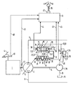
- the hydraulic pump 2 is a reversible, i.e. Pump delivering in two conveying directions with an adjustable, speed-dependent delivery volume, which is in fluid communication with the hydraulic motor via two working lines 5, 6; otherwise, the hydrostatic transmission is of a known design and is therefore not further described.
- the arrangement according to the invention for adjusting the delivery volume of the hydraulic pump 2 comprises a so-called hydraulic DA (for speed-dependent) device 7 for generating a control fluid with a control pressure proportional to the speed of the drive motor 1, an actuating device 8 which is connected to the actuator 9 of the hydraulic pump 2 Adjusting the delivery volume is coupled, a control valve 10 for controlling the supply of the control fluid to the actuating device 8, an electrically controllable actuating device 11 for the control valve 10, a feedback device 12 which detects the delivery volume setting of the hydraulic pump 2 and reports back to the control valve 10, and an electronic control unit 13 for outputting control signals to the actuating device 11.
- a so-called hydraulic DA (for speed-dependent) device 7 for generating a control fluid with a control pressure proportional to the speed of the drive motor 1
- an actuating device 8 which is connected to the actuator 9 of the hydraulic pump 2 Adjusting the delivery volume is coupled
- a control valve 10 for controlling the supply of the control fluid to the actuating device 8
- the DA device 7 enables so-called automotive driving, in which the delivery volume of the hydraulic pump 2 is proportional to the speed of the drive motor 1 is adjusted.
- the DA device 7 comprises an auxiliary pump 15 of constant delivery volume mechanically coupled to the hydraulic pump 2 via a through shaft 14 and with a delivery direction, as well as a control valve 16, usually referred to as a DA control valve, with a measuring orifice 17 shown here outside it.
- the DA control valve 16 opens, so that at its outlet and in a control pressure medium line 23 connected to it, the speed-proportional control pressure builds up, which counteracts the pressure difference at the measuring orifice 17 and the DA control valve 16 adjusted in the direction of the closed position until there is a force balance on its valve body.
- the signal pressure counteracting the pressure difference at the orifice 17 is directly proportional to the speed-proportional volume flow conveyed by the auxiliary pump 15 and thus to the speed of the drive motor 1.
- the control valve 10 is arranged in the control fluid line 23 and divides it into a main line section 31 leading to the DA control valve 16 and two branch line sections 32, 33, which lead to the control rooms 26, 27 of the actuating cylinder 8.
- the control valve 10 is a continuously adjustable 4/3-way valve, which in a known manner comprises a valve piston 34 and a valve sleeve 35 and each has a working connection T to a discharge line 36 leading to the tank 19, a working connection P to the main line section 31 of the control fluid line 23 and each has a working connection A, B to the branch line sections 32, 33.
- the control valve 10 is held by two valve centering springs 37, 38 in the (spring-centered) central position shown in the figure, in which all connections A, B, P and T are blocked and the hydraulic pump 2 is set to zero delivery volume.
- the control valve 10 is assigned a travel direction switch 39 which can be set to idle L, forward travel V and reverse travel R and a potentiometer 40 for detecting the respective position of the switch 39.
- the electronic control unit 13 is connected to the potentiometer 40 of the travel direction switch 39, via a signal line 45 to the sensor 30 for detecting the travel of the actuating piston 24 and to a first sensor 46 for detecting the setpoint speed of the drive motor 1 predetermined with the accelerator pedal 4 and a second sensor 47 for detecting the actual speed of the drive motor 1 each connected via a signal line 48, 49.
- control fluid loaded with the speed-proportional control pressure flows into the right pressure chamber 26 or left pressure chamber 27 of the actuating cylinder 8 and moves the actuating piston 24 in the direction of its left or right end position until the balance between the force of the respectively compressed centering spring 29 or 28 and the self-restoring force of the hydraulic pump 2 on the one hand and the hydraulic force of the signal pressure on the other hand.
- the end positions of the actuating piston 24 correspond to the maximum delivery volume of the hydraulic pump 2 in the respective flow direction.
- the setting of the control piston 24 begins in the direction of the middle position as soon as the above-mentioned speed and control pressure values are below the corresponding maximum values.
- the electronic control unit 13 detects the respective position of the actuating piston 24 via the output signal of the sensor 30 and amplifies the first control signal when the actuating piston 24 moves in the direction of its respective end position in proportion to the distance traveled by it and weakens it when the actuating piston moves in the direction of it Middle position also proportional to the travel.
- valve sleeve 35 via the return lever 12
- valve piston 34 via changes in the first control signal
- the feedback device 12 is ineffective, so that the control piston 24 is adjusted only by the speed-proportional signal pressure and thus the delivery volume of the hydraulic pump 2 as a function of the speed of the drive motor 1 along the predetermined signal pressure / speed characteristic.
- the actuating piston 24 of the Actuating cylinder 8 is moved to the right in the direction of its central position until the valve sleeve 35 following this movement via the return lever 12 reaches the position corresponding to the central position of the control valve 10, ie the control valve 10 closes.
- the actuating piston 24 is dependent on the volume of the actuating pressure medium flowing out of the right or left pressure chamber 26 or 27, which is proportional to the strength of the control signal and thus the speed depression of the drive motor 1, in the direction of its central position and thus the hydraulic pump 2 to the corresponding smaller delivery volume adjusted.
- the latter absorbs a lower torque corresponding to the smaller delivery volume, as a result of which the overload of the drive motor 1 is eliminated and the drop in speed is prevented.
- the hydraulic pump can - depending on the control of the control valve 10 with the second control signal - independently of the speed of the drive motor not only along any desired characteristic curve, for example, essentially perpendicular to the speed depression coordinate axis, but also up to each desired delivery volume are pivoted back, in which the torque absorbed by it is, for example, less than the drive torque of the drive motor.
- the power released in this way can, for example, be taken up by an additional consumer without a speed drop occurring beforehand.
- the device according to the invention thus enables both the conventional limit load control (pivoting back of the hydraulic pump to a delivery volume in which the torque it absorbs is equal to the torque output by the drive motor) and also a control going beyond this.
- Both controls can be carried out over the entire speed range of the drive motor. This is particularly advantageous when driving in the lower speed range before the drive motor develops its maximum torque.
- the hydraulic limit load control known from the prior art would under Using the DA device, a torque balance between the hydraulic pump and the drive motor can only be achieved with very high pressure, if at all, since the torque of the drive motor decreases with increasing speed drop in the lower speed range mentioned.
- the above mechanical feedback device is described here for the sake of simplicity in connection with the electronic control unit, but is mainly intended for use without it.
Abstract
Description
Die Erfindung bezieht sich auf eine Vorrichtung zum Verstellen des Fördervolumens einer Hydropumpe nach dem Oberbegriff des Anspruches 1.The invention relates to a device for adjusting the delivery volume of a hydraulic pump according to the preamble of
Aus der DE 38 07 599 A1 ist eine derartige Vorrichtung zum Verstellen des Fördervolumens einer Hydropumpe bekannt, die Teil eines hydrostatischen Getriebes für einen Fahrantrieb eines Fahrzeuges ist. Aufgrund deren hydraulischer DA-Einrichtung (drehzahlabhängigen Einrichtung) ermöglicht diese bekannte Vorrichtung das sog. automotive Fahren, bei dem die Hydropumpe mit zunehmender Drehzahl des Antriebsmotors auf größeres Fördervolumen verstellt wird, wodurch das Fahrzeug mit einer größeren Fahrgeschwindigkeit fährt, als der Drehzahl des Antriebsmotors entspricht. Das Verstellen der Hydropumpe geschieht mit Hilfe eines drehzahlproportionalen Stelldrucks, wobei die Steigung der Kennlinie dieses Stelldrucks über der Drehzahl durch die Auslegung der DA-Einrichtung bestimmt ist. Die jeweilige Fahrtrichtung wird mit dem als schaltendes Fahrtrichtungsventil mit zwei Durchfluß-Endstellungen für Vorwärtsfahrt und für Rückwärtsfahrt ausgebildeten Steuerventil vorgegeben. Die bekannte Vorrichtung verleiht dem Fahrzeug nicht nur ein weiches, elastisches und feinfühliges Fahrverhalten, sondern zeichnet sich auch durch die sog. Grenzlastregelungsfunktion aus. Diese verhindert, daß bei Belastung des Antriebs aus den Fahrzuständen und/oder aus den Lastzuständen von Zusatzgeräten das maximale Antriebsmoment des Antriebsmotors bei zulässigen Drehzahldrückungswerten nicht überschritten wird. Wenn also der Antriebsmotor durch Aufnahme einer zusätzlichen Last in seiner Drehzahl gedrückt wird, so führt dies zu einer Reduzierung des Stelldrucks und damit des Fördervolumens der Hydropumpe so lange, bis Gleichgewicht zwischen dem vom Antriebsmotor abgegebenen und dem von der Hydropumpe aufgenommenen Drehmoment besteht.From DE 38 07 599 A1, such a device for adjusting the delivery volume of a hydraulic pump is known, which is part of a hydrostatic transmission for a travel drive of a vehicle. Because of its hydraulic DA device (speed-dependent device), this known device enables so-called automotive driving, in which the hydraulic pump is adjusted to a greater delivery volume with increasing speed of the drive motor, as a result of which the vehicle travels at a greater driving speed than the speed of the drive motor . The hydraulic pump is adjusted with the aid of a signal pressure proportional to the speed, the gradient of the characteristic of this signal pressure over the speed being determined by the design of the DA device. The respective direction of travel is specified with the control valve designed as a switching directional valve with two flow limit positions for forward travel and for reverse travel. The known device not only gives the vehicle a soft, elastic and sensitive driving behavior, but is also characterized by the so-called limit load control function. This prevents the maximum drive torque of the drive motor from being exceeded with permissible speed pressure values when the drive is loaded from the driving states and / or from the load states of additional devices. If the drive motor is pressed in its speed by taking up an additional load, this leads to a reduction in the signal pressure and thus the delivery volume of the hydraulic pump until there is a balance between the torque delivered by the drive motor and the torque absorbed by the hydraulic pump.
Die Antriebsleistung des Motors fällt jedoch umso stärker ab, je größer die Drehzahldrückung ist. Mit dem sog. "Teil-Inchen" wird die Drehzahldrückung reduziert und damit die Antriebsleistung erhöht. Dieses Teil-Inchen ist beispielsweise auf Seite 12 des technischen Merkblatts RD 92000/02.83 der Firma Hydromatik GmbH beschrieben; es wird mit Hilfe einer Teilinch-Einrichtung in Form eines mechanischen Gestänges durchgeführt, welches das Gaspedal mit dem den drehzahlproportionalen Stelldruck erzeugenden sog. DA-Regelventil der DA-Einrichtung verbindet und ab einem vorgegebenen Drehzahlwert unterhalb der maximalen Drehzahl des Antriebsmotors einen weiteren Anstieg des Stelldrucks verhindert. Mit anderen Worten, bei diesem vorgegebenen Drehzahlwert ist der maximale Stelldruck und damit das maximale Fördervolumen der Hydropumpe erreicht; bei weiterem Drehzahlanstieg wird die Kennlinie des Stelldrucks über der Drehzahl parallel zur Drehzahl-Koordinatenachse verschoben. Dabei ist das Teil-Inchen so ausgelegt, daß diese Verschiebung der Kennlinie erst in dem Drehzahlbereich beginnt, in dem der Antriebsmotor sein maximales Antriebsmoment entwickelt. Zusätzlich zum vorerwähnten Vorteil der optimalen Ausnutzung der Antriebsleistung während der Grenzlastregelung bietet das Teil-Inchen einen weiteren Vorteil, nämlich den, daß bei Fahrt mit nicht überlastetem Antriebsmotor das maximale Antriebsmoment nicht erst bei maximaler Drehzahl, sondern bei niedrigeren Drehzahlen genutzt wird - da bei diesen die Hydropumpe bereits auf maximales Fördervolumen eingestellt ist -, was sich vorteilhaft auf Kraftstoffverbrauch und Geräuschentwicklung auswirkt.However, the greater the speed reduction, the more the engine's drive power drops. The so-called "partial inching" reduces the speed drop and thus increases the drive power. This partial inch is described, for example, on
Es ist Aufgabe der Erfindung, die Vorrichtung der eingangs genannten Art so weiterzubilden, daß eine bessere Anpassung des Drehmomentes des Antriebsmotors an die Fahrzeugbelastung ermöglicht wird.It is an object of the invention to further develop the device of the type mentioned in the introduction so that a better adaptation of the torque of the drive motor to the vehicle load is made possible.
Diese Aufgabe wird durch die kennzeichnenden Merkmale des Anspruches 1 in Verbindung mit dessen gattungsbildenden Merkmalen gelöst. Die Verstellung der Hydropumpe bei Fahrt mit nicht überlastetem Antriebsmotor erfolgt, wie bisher im Stand der Technik, in Abhängigkeit von dem von der hydraulischen DA-Einrichtung erzeugten drehzahlproportionalen Stelldruck. Im Gegensatz zum Stand der Technik jedoch wird die Hydropumpe während der Grenzlastregelung in Abhängigkeit von dem der Ansteuerung des Steuerventils proportionalen Volumen des Stelldruckmittels auf kleineres Fördervolumen verstellt.This object is achieved by the characterizing features of
Es werden also zwei voneinander unabhängige Steuerungen zur Verstellung der Hydropumpe verwendet; folglich ist die erfindungsgemäße Vorrichtung ohne Berücksichtigung der Erfordernisse der bisherigen Grenzlastregelung, also ohne Teilinch-Einrichtung, ausgebildet. Das automotive Fahren erfolgt lediglich bei nicht überlastetem Antriebsmotor mit Hilfe der DA-Einrichtung; durch entsprechende Auslegung derselben sowie der Stelleinrichtung und Abstimmung dieser beiden Einrichtungen auf die Hydropumpe kann automotiv auf der Grundlage beliebig steiler Fördervolumen/Drehzahl-Kennlinien gefahren werden, so daß die Hydropumpe ebenso wie im Fall der Vorrichtung gemäß dem Stand der Technik mit Teilinch-Einrichtung bei niedrigeren Drehzahlen als der maximalen Drehzahl auf maximales Fördervolumen ausgeschwenkt ist, z.B. dann, wenn der Antriebsmotor sein maximales Antriebsmoment entwickelt. Das maximale Antriebsmoment wird also wie bei Verwendung einer Teilinch-Einrichtung bereits bei niedrigeren Drehzahlen erreicht und damit der Kraftstoffverbrauch gesenkt und die Geräuschentwicklung verringert.So two independent controls are used to adjust the hydraulic pump; consequently, the device according to the invention is designed without taking into account the requirements of the previous limit load regulation, that is to say without a partial inch device. Automotive driving takes place only if the drive motor is not overloaded using the DA device; by appropriate design of the same as well as the adjusting device and coordination of these two devices on the hydraulic pump can be driven automatically on the basis of any steep delivery volume / speed characteristics, so that the hydraulic pump as well as in the case of the device according to the prior art with partial inch device lower speeds than the maximum speed is swung out to the maximum delivery volume, for example when the drive motor develops its maximum drive torque. The maximum drive torque is thus achieved at lower speeds, as when using a part-inch device, and thus fuel consumption is reduced and noise is reduced.
Die drehzahlunabhängige Verstellung des Fördervolumens der Hydropumpe bei Drückung des Antriebsmotors erfolgt durch Ansteuerung eines Steuerventils durch eine vorzugsweise elektronische Steuereinheit in Abhängigkeit von der Drehzahl oder der Drehzahldrückung, so daß das Steuerventil in einen Durchflußverstellbereich verstellt wird, in dem die Stelleinrichtung an den Tank angeschlossen und die beim automotiven Fahren unwirksame Rückführeinrichtung wirksam ist, so daß die Hydropumpe entsprechend der Stärke des Steuersignals entlang jeder gewünschten, beispielsweise in der elektronischen Steuereinheit gespeicherten und vorzugsweise beliebig veränderbaren Fördervolumen/Drehzahl-Kennlinie oder Fördervolumen/Drehzahldrückungs-Kennlinie auf kleineres Fördervolumen zurückgeschwenkt werden kann. Auf diese Weise ist es möglich, die Grenzlastregelung mit jeder beliebigen Drehzahldrückung durchzuführen. Verläuft die Fördervolumen-Kennlinie im wesentlichen senkrecht zur Drehzahl- bzw. Drehzahldrückungs-Koordinatenachse, so erfolgt die Grenzlastregelung praktisch ohne Drehzahldrückung. Erfindungsgemäß wird die Antriebsleistung ohne Verwendung einer Teilinch-Einrichtung optimal ausgenutzt, und zwar über den gesamten Drehzahlbereich, also mit dem Vorteil, daß die Grenzlastregelung auch bei nicht auf maximales Fördervolumen ausgeschwenkter Hydropumpe entlang jeder gewünschten Kennlinie durchgeführt werden kann.The speed-independent adjustment of the delivery volume of the hydraulic pump when the drive motor is pressed is carried out by controlling a control valve by a preferably electronic control unit as a function of the speed or the speed reduction, so that the control valve is adjusted in a flow adjustment range in which the control device is connected to the tank and the in automotive driving ineffective feedback device is effective so that the hydraulic pump can be pivoted back to a smaller delivery volume according to the strength of the control signal along any desired, for example stored in the electronic control unit and preferably arbitrarily variable delivery volume / speed characteristic or delivery volume / speed depression characteristic. In this way, it is possible to carry out the limit load control with any speed reduction. If the delivery volume characteristic curve is essentially perpendicular to the speed or speed reduction coordinate axis, the limit load control takes place practically without speed reduction. According to the invention, the drive power is optimally used without the use of a partial inch device, specifically over the entire speed range, with the advantage that the limit load control can be carried out along any desired characteristic curve even when the hydraulic pump is not swung out to the maximum delivery volume.
Weitere Merkmale und Vorteile der Erfindung ergeben sich aus den Unteransprüchen.Further features and advantages of the invention emerge from the subclaims.
Nachstehend ist die erfindungsgemäße Vorrichtung zum Verstellen des Fördervolumens einer Hydropumpe anhand eines Ausführungsbeispiels unter Bezugnahme auf den Schaltplan der einzigen Figur näher beschrieben, die einen hydrostatischen Fahrantrieb eines Fahrzeugs zeigt.The device according to the invention for adjusting the delivery volume of a hydraulic pump is described in more detail below using an exemplary embodiment and with reference to the circuit diagram of the single figure, which shows a hydrostatic travel drive of a vehicle.
Dieser hydrostatische Fahrantrieb umfaßt einen Antriebsmotor 1, ein hydrostatisches Getriebe mit einer Hydropumpe 2 verstellbaren Fördervolumens und einen nicht gezeigten Hydromotor für den Antrieb der Antriebsräder des Fahrzeugs sowie die erfindungsgemäße Vorrichtung zum Verstellen des Fördervolumens der Hydropumpe 2.This hydrostatic travel drive comprises a
Der Antriebsmotor 1 ist ein über eine Antriebswelle 3 mechanisch mit der Hydropumpe 2 gekoppelter Brennkraftmotor, wie etwa ein Dieselmotor, dessen Kraftstoffzufuhr und damit dessen Drehmoment bzw. Drehzahl mittels eines Gaspedals 4 verstellbar ist.The
Die Hydropumpe 2 ist eine reversierbare, d.h. in zwei Förderrichtungen fördernde Pumpe mit einem verstellbaren, drehzahlabhängigen Fördervolumen, die im geschlossenen Kreislauf über zwei Arbeitsleitungen 5, 6 mit dem Hydromotor in Fluidverbindung steht; im übrigen ist das hydrostatische Getriebe von bekannter Ausführung und deshalb nicht weiter beschrieben.The hydraulic pump 2 is a reversible, i.e. Pump delivering in two conveying directions with an adjustable, speed-dependent delivery volume, which is in fluid communication with the hydraulic motor via two
Die erfindungsgemäße Anordnung zum Verstellen des Fördervolumens der Hydropumpe 2 umfaßt eine sog. hydraulische DA(für drehzahlabhängig)-Einrichtung 7 zum Erzeugen eines Steuerfluids mit einem zur Drehzahl des Antriebsmotors 1 proportionalen Stelldruck, eine Stelleinrichtung 8, die mit dem Stellglied 9 der Hydropumpe 2 zum Verstellen des Fördervolumens derselben gekoppelt ist, ein Steuerventil 10 zur Steuerung der Zufuhr des Steuerfluids zur Stelleinrichtung 8, eine elektrisch ansteuerbare Betätigungseinrichtung 11 für das Steuerventil 10, eine Rückführeinrichtung 12, die die Fördervolumen-Einstellung der Hydropumpe 2 erfaßt und zum Steuerventil 10 rückmeldet, sowie eine elektronische Steuereinheit 13 zur Ausgabe von SteuersignaIen an die Betätigungseinrichtung 11.The arrangement according to the invention for adjusting the delivery volume of the hydraulic pump 2 comprises a so-called hydraulic DA (for speed-dependent) device 7 for generating a control fluid with a control pressure proportional to the speed of the
Die DA-Einrichtung 7 ermöglicht das sog. automotive Fahren, bei dem das Fördervolumen der Hydropumpe 2 proportional zur Drehzahl des Antriebsmotors 1 verstellt wird. Die DA-Einrichtung 7 umfaßt eine mit der Hydropumpe 2 über eine Durchgangswelle 14 mechanisch gekoppelte Hilfspumpe 15 konstanten Fördervolumens und mit einer Förderrichtung sowie ein Regelventil 16, üblicherweise als DA-Regelventil bezeichnet, mit einer hier außerhalb desselben eingezeichneten Meßblende 17.The DA device 7 enables so-called automotive driving, in which the delivery volume of the hydraulic pump 2 is proportional to the speed of the
Eine Ansaugleitung 18 verbindet den Tank 19 mit dem Eingang der Steuerpumpe 15, deren Ausgang über eine Anschlußleitung 20 mit dem ständig offenen Eingang des DA-Regelventils 16 in Verbindung steht.An
Das DA-Regelventil 16 ist ein Differenzdruckregelventil mit ständigem gedrosseltem Ablauf zum Tank 19. Dieser Ablauf ermöglicht eine ständige Strömung des von der Hilfspumpe 15 geförderten, der Drehzahl des Antriebsmotors 1 direkt proportionalen Volumenstroms und damit den Aufbau einer drehzahlproportionalen Druckdifferenz zwischen dem Ausgangsdruck der Hilfspumpe 15 in Strömungsrichtung vor und dem Druck in Strömungsrichtung nach der Meßblende 17. Das DA-Regelventil 16, auch als Druckwaage bezeichnet, ist von allgemein bekannter Ausführung und deshalb nicht näher beschrieben. Seine Funktion besteht darin, aus der Druckdifferenz an der Meßblende 17 einen drehzahlproportionalen Stelldruck abzuleiten. Zu diesem Zweck wird sein Ventilkörper von der Druckdifferenz gegen die Kraft einer einstellbaren Feder 22 in Richtung Offenstellung beaufschlagt. Sobald die hydraulische Kraft der Druckdifferenz die Federkraft übersteigt, öffnet das DA-Regelventil 16, so daß sich an seinem Ausgang und in einer an diesen angeschlossenen Stelldruckmittelleitung 23 der drehzahlproportionale Stelldruck aufbaut, der der Druckdifferenz an der Meßblende 17 entgegenwirkt und das DA-Regelventil 16 so lange in Richtung Schließstellung verstellt, bis Kraftgleichgewicht an seinem Ventilkörper herrscht. Auf diese Weise wird erreicht, daß der der Druckdifferenz an der Meßblende 17 entgegenwirkende Stelldruck dem von der Hilfspumpe 15 geförderten drehzahlproportionalen Volumenstrom und damit der Drehzahl des Antriebsmotors 1 direkt proportional ist.The DA control valve 16 is a differential pressure control valve with a constant throttled outlet to the
Die Stelleinrichtung 8 ist als doppeltwirkender hydraulischer Gleichgang-Stellzylinder ausgebildet, dessen Stellkolben 24 über die Kolbenstange 25 mit dem Stellglied 9 zum Verstellen des Fördervolumens der Hydropumpe 2 gekoppelt ist und zwei Steuerräume 26, 27 begrenzt, in denen je eine Zentrierfeder 28, 29 angeordnet ist, die den Stellkolben 24 in Richtung einer dem Null-Fördervolumen der Hydropumpe 2 entsprechenden Mittelstellung federzentriert. Der Stelleinrichtung 8 ist ein Sensor 30 zum Erfassen des Stellwegs und der Stellrichtung des Stellkolbens 24 bzw. der Kolbenstange 25 zugeordnet.The actuating
Das Steuerventil 10 ist in der Steuerfluidleitung 23 angeordnet und teilt diese in einen zum DA-Regelventil 16 führenden Hauptleitungsabschnitt 31 und zwei Zweigleitungsabschnitte 32, 33, die zu den Steuerräumen 26, 27 des Stellzylinders 8 führen. Das Steuerventil 10 ist ein stetig verstellbares 4/3-Wegeventil, das in bekannter Weise einen Ventilkolben 34 sowie eine Ventilhülse 35 umfaßt und je einen Arbeitsanschluß T an eine zum Tank 19 führende Entlastungsleitung 36, einen Arbeitsanschluß P an den Hauptleitungsabschnitt 31 der Steuerfluidleitung 23 sowie je einen Arbeitsanschluß A, B an die Zweigleitungsabschnitte 32, 33 aufweist. Das Steuerventil 10 ist durch zwei Ventil-Zentrierfedern 37, 38 in der in der Figur gezeigten (federzentrierten) Mittelstellung gehalten, in der sämtliche Anschlüsse A, B, P und T gesperrt und die Hydropumpe 2 auf Null-Fördervolumen eingestellt ist. Dem Steuerventil 10 ist ein auf Leerlauf L, Vorwärtsfahrt V und Rückwärtsfahrt R einstellbarer Fahrtrichtungs-Schalter 39 und ein Potentiometer 40 zum Erfassen der jeweiligen Stellung des Schalters 39 zugeordnet.The
Die Betätigungseinrichtung 11 für das Steuerventil 10 ist eine Proportional-Betätigungseinrichtung, die zwei Proportionalmagnete 41, 42 umfaßt, die an den einander gegenüberliegenden Enden des Ventilkolbens 34 zur stufenlosen Verstellung desselben vorgesehen und über je eine Steuersignalleitung 43, 44 an die elektronische Steuereinheit 13 angeschlossen sind.The actuating device 11 for the
Die Kolbenstange 25 des Stellzylinders 8 ist mechanisch mit der Ventilhülse 35 des Steuerventils 10 derart zwangsgekoppelt, daß diese mit gleichem Richtungssinn und gleicher Geschwindigkeit bewegt werden.The
Die elektronische Steuereinheit 13 ist an das Potentiometer 40 des Fahrtrichtungs-Schalters 39, über eine Signalleitung 45 an den Sensor 30 zum Erfassen des Stellwegs des Stellkolbens 24 sowie an einen ersten Sensor 46 zum Erfassen der mit dem Gaspedal 4 vorgegebenen Solldrehzahl des Antriebsmotors 1 und einen zweiten Sensor 47 zum Erfassen der Istdrehzahl des Antriebsmotors 1 über je eine Signalleitung 48, 49 angeschlossen.The
Die im vorliegenden Zusammenhang interessierende Funktion der elektronischen Steuereinheit 13 besteht u.a. darin, die Ausgangssignale der Sensoren 46, 47, d.h. die mit dem Gaspedal 4 jeweils vorgegebene Solldrehzahl des Antriebsmotors 1 und dessen jeweilige Istdrehzahl ständig miteinander zu vergleichen und bei Drehzahlgleichheit ein erstes Steuersignal und bei einer Drehzahldrückung des Antriebsmotors, d.h. bei einem durch Überlastung verursachten Rückgang seiner Istdrehzahl um einen vorgegebenen, einstellbaren Betrag gegenüber seiner Solldrehzahl ein zweites, der Drehzahldrückung proportionales Steuersignal an die Ansteuereinrichtung 11 auszugeben. In der elektronischen Steuereinheit 13 ist eine Steuersignal/Drehzahldrückungs-Kennlinie gespeichert, deren Steigung beliebig verändert werden kann. Statt dieser einen Kennlinie können aber auch mehrere Kennlinien mit jeweils unterschiedlicher Steigung gespeichert sein, aus denen die jeweils gewünschte ausgewählt wird.The function of the
Die Ausgabe des ersten Steuersignals erfolgt bei Stellung des Fahrtrichtungsschalters 39 auf V an den rechten und bei Stellung auf R an den linken Proportionalmagneten 41 bzw. 42. Dadurch wird das Steuerventil 10 (bzw. dessen Ventilkolben 34) in eine linke bzw. rechte Durchfluß-Endstellung mit freiem Durchflußquerschnitt überführt, in der seine Arbeitsanschlüsse P und B sowie A und T bzw. P und A sowie T und B miteinander verbunden sind. Dementsprechend strömt das mit dem drehzahlproportionalen Stelldruck beladene Steuerfluid in den rechten Druckraum 26 bzw. linken Druckraum 27 des Stellzylinders 8 ein und verschiebt den Stellkolben 24 in Richtung seiner linken bzw. rechten Endstellung so lange, bis Gleichgewicht zwischen der Kraft der jeweils zusammengedrückten Zentrierfeder 29 bzw. 28 sowie der Eigenrückstellkraft der Hydropumpe 2 einerseits und der hydraulischen Kraft des Stelldrucks andererseits herrscht. Die Endstellungen des Stellkolbens 24 entsprechen dem maximalen Fördervolumen der Hydropumpe 2 in der jeweiligen Stromrichtung. Die DA-Einrichtung 7 und die Zentrierfedern 28, 29 der Stelleinrichtung 8 sind so ausgebildet und auf die Eigenrückstellkräfte der Hydropumpe 2 abgestimmt, daß letztere auf maximales Fördervolumen bei derjenigen Drehzahl ausgeschwenkt ist, bei der der Antriebsmotor sein maximales Antriebsmoment entwickelt; diese Drehzahl und der zugeordnete Stelldruck sind kleiner als die entsprechenden Maximalwerte.The output of the first control signal takes place when the
Bei Drehzahl- und damit Stelldruckreduzierung beginnt die Rückstellung des Stellkolbens 24 in Richtung Mittelstellung, sobald die vorerwähnten Drehzahl- und Stelldruckwerte unterhalb der entsprechenden Maximalwerte sind. Die elektronische Steuereinheit 13 erfaßt dabei über das Ausgangssignal des Sensors 30 die jeweilige Stellung des Stellkolbens 24 und verstärkt das erste Steuersignal bei Bewegung des Stellkolbens 24 in Richtung seiner jeweiligen Endstellung proportional zu der von ihm zurückgelegten Wegstrecke und schwächt es bei Bewegung des Stellkolbens in Richtung seiner Mittelstellung ebenfalls proportional zum Stellweg ab. Auf diese Weise werden die Ventilhülse 35 (über den Rückführhebel 12) und der Ventilkolben 34 (über Änderungen des ersten Steuersignals) bei Bewegungen des Stellkolbens 24 im gleichen Richtungssinn und um die gleiche Wegstrecke verstellt, so daß die jeweilige Durchfluß-Endstellung während der gesamten Dauer der Ansteuerung mit dem ersten Steuersignal aufrechterhalten wird. Mit anderen Worten, die Rückführeinrichtung 12 ist unwirksam, so daß der Stellkolben 24 lediglich durch den drehzahlproportionalen Stelldruck und damit das Fördervolumen der Hydropumpe 2 in Abhängigkeit von der Drehzahl des Antriebsmotors 1 entlang der vorgegebenen Stelldruck/Drehzahl-Kennlinie verstellt wird.When the speed and thus the control pressure are reduced, the setting of the
Die Ausgabe des zweiten Steuersignals erfolgt bei unveränderter Fahrtrichtung an den dem bisher vom ersten Steuersignal angesteuerten Proportionalmagneten 41 oder 42 jeweils gegenüberliegenden Proportionalmagneten 42 bzw. 41, der dementsprechend den Ventilkolben 34 des Steuerventils 10 von seiner vorhergehenden rechten oder linken Endstellung nach links bzw. nach rechts über die Mittelstellung hinaus verstellt. In der beispielsweise rechten Endstellung ist der Durchfluß vom Arbeitsanschluß P nach A sowie der von B nach T geöffnet, so daß der bisher mit der Steuerfluidleitung 23 verbundene rechte Steuerraum 26 des Stellzylinders 8 zum Tank 19 hin entlastet ist, während gleichzeitig Steuerfluid in den bisher an den Tank 19 angeschlossenen linken Steuerraum 27 einströmt. Dadurch wird der Stellkolben 24 des Stellzylinders 8 nach rechts in Richtung seiner Mittelstellung so lange bewegt, bis die dieser Bewegung über den Rückführhebel 12 folgende Ventilhülse 35 in die der Mittelstellung des Steuerventils 10 entsprechende Position gelangt, d.h. das Steuerventil 10 schließt. Mit anderen Worten, der Stellkolben 24 wird in Abhängigkeit von dem aus dem rechten oder linken Druckraum 26 bzw. 27 ausströmenden, der Stärke des Steuersignals und damit der Drehzahldrückung des Antriebsmotors 1 proportionalen Volumen des Stelldruckmittels in Richtung seiner Mittelstellung und damit die Hydropumpe 2 auf entsprechendes kleineres Fördervolumen verstellt. Letztere nimmt dabei ein dem kleineren Fördervolumen entsprechendes geringeres Drehmoment auf, wodurch die Überlastung des Antriebsmotors 1 aufgehoben und Drehzahlabfall verhindert wird.The output of the second control signal takes place with the direction of travel unchanged at the proportional magnet 42 or 41 respectively opposite the previously actuated proportional magnet 41 or 42, which accordingly correspondingly moves the valve piston 34 of the
Diese Entlastung des Antriebsmotors 1 durch die elektronische, volumenabhängige Steuerung der Hydropumpe 2 erfolgt somit unabhängig von deren hydraulischen, stelldruck- bzw. drehzahlabhängigen Steuerung.This relief of the
Mit der elektronischen, volumenabhängigen Steuerung kann also - entsprechend der Ansteuerung des Steuerventils 10 mit dem zweiten Steuersignal - die Hydropumpe unabhängig von der Drehzahl des Antriebsmotors nicht nur entlang jeder gewünschten, beispielsweise im wesentlichen senkrecht zur Drehzahldrückungs-Koordinatenachse verlaufenden Kennlinie, sondern auch bis zu jedem gewünschten Fördervolumen zurückgeschwenkt werden, bei dem das von ihr aufgenommene Drehmoment z.B. kleiner als das Antriebsmoment des Antriebsmotors ist. Die dabei freigewordene Leistung kann z.B. von einem zusätzlichen Verbraucher abgenommen werden, ohne daß zuvor eine Drehzahldrückung auftritt. Damit ermöglicht die erfindungsgemäße Vorrichtung sowohl die herkömmliche Grenzlastregelung (Zurückschwenken der Hydropumpe auf ein solches Fördervolumen, bei dem das von ihr aufgenommene Drehmoment gleich dem vom Antriebsmotor abgegebenen Drehmoment ist) als auch eine darüber hinausgehende Regelung. Beide Regelungen können über den gesamten Drehzahlbereich des Antriebsmotors durchgeführt werden. Dies ist insbesondere vorteilhaft beim Fahren im unteren Drehzahlbereich, bevor der Antriebsmotor sein maximales Drehmoment entwickelt. In einem solchen Fall würde bei der aus dem Stand der Technik bekannten hydraulischen Grenzlaststeuerung unter Verwendung der DA-Einrichtung ein Drehmomentengleichgewicht zwischen Hydropumpe und Antriebsmotor nur bei sehr großer Drückung, wenn überhaupt, erreicht werden, da mit zunehmendem Drehzahlabfall im genannten unteren Drehzahlbereich sich das Drehmoment das Antriebsmotors verringert.With the electronic, volume-dependent control system, the hydraulic pump can - depending on the control of the
Die vorstehende mechanische Rückführeinrichtung ist hier der Einfachheit halber in Verbindung mit der elektronischen Steuereinheit beschrieben, ist jedoch hauptsächlich für den Einsatz ohne diese vorgesehen. Bei Einsatz einer elektronischen Steuereinheit bietet es sich an, die Rückführung des Steuerventils in seine Schließstellung bei Drückung des Antriebsmotors durch Abschwächen des zweiten Steuersignals durchzuführen und diese Rückführung beim automotiven Fahren durch entsprechende Veränderung des ersten Steuersignals auszugleichen, d.h. unwirksam zu machen.The above mechanical feedback device is described here for the sake of simplicity in connection with the electronic control unit, but is mainly intended for use without it. When using an electronic control unit, it is advisable to return the control valve to its closed position when the drive motor is depressed by weakening the second control signal and to compensate for this feedback when driving by changing the first control signal accordingly, i.e. to render ineffective.
Claims (6)
mit einer mit dem Antriebsmotor (1) gekoppelten Steuerpumpe (15), welche einen drehzahlabhängigen Stelldruck erzeugt und den Steuerfluid für eine drehzahlabhängige Einrichtung (DA-Einrichtung) (7) bereitstellt,
mit einer einen Stellkolben aufweisenden Stelleinrichtung (8) zum Verstellen des Fördervolumens der Hydropumpe (2), und mit einem Steuerventil (10), das durch eine elektronisch ansteuerbare Betätigungseinrichtung (11) in zwei gegenüberliegende Endstellungen überführbar ist, in denen die Stelleinrichtung (8) und damit das Fördervolumen der Hydropumpe (2) stelldruckabhängig veränderbar ist,
dadurch gekennzeichnet,
daß das Steuerventil (10) eine Steuerhülse (35) aufweist, die relativ zum Steuerkolben (34) des Steuerventils (10) axial verschiebbar und mit dere Bewegung des Stellkolbens (24) der Stelleinrichtung (8) zwangsgekoppelt ist, daß das Steuerventil (10) als ein stufenlos verstellbares Vierwegeventil ausgebildet ist, welches in einer Mittelstellung den Durchfluß des Steuerfluids zu der Stelleinrichtung (8) sperrt und in den beiden Endstellungen den Stellkolben (24) in eine jeweils entgegengesetzte Richtung betätigt,
daß bei einer Übereinstimmung der Soll- und Ist-Drehzahlwerte des Antriebsmotors (1) der Steuerkolben (34) synchron zur Bewegung der Steuerhülse (35) des Steuerventils (10) nachgeführt und das Fördervolumen der Hydropumpe (2) auf das der Drehzahl des Antriebsmotors (1) entsprechende, größtmögliche Drehmoment erhöht wird, welches von der elektronischen Steuerung (13) vorgegeben ist, daß bei einem infolge einer Überlastung des Antriebsmotors (1) auftretenden Drehzahlabfall (Drehzahldrückung) der Steuerkolben (34) und die Steuerhülse (35) unabhängig voneinander betätigt werden und das Fördervolumen der Hydropumpe (2) um ein vorgegebenes Maß verringert wird.Arrangement for the load-dependent adjustment of the delivery volume of a hydraulic pump (2), which is part of a hydrostatic transmission and can be driven by a drive motor (1) with an adjustable speed,
with a control pump (15) coupled to the drive motor (1), which generates a speed-dependent signal pressure and provides the control fluid for a speed-dependent device (DA device) (7),
With an actuating device (8) having an actuating piston for adjusting the delivery volume of the hydraulic pump (2), and with a control valve (10) which can be moved into two opposite end positions by an electronically controllable actuating device (11), in which the actuating device (8) and thus the delivery volume of the hydraulic pump (2) can be changed depending on the signal pressure,
characterized,
that the control valve (10) has a control sleeve (35) which is axially displaceable relative to the control piston (34) of the control valve (10) and is positively coupled to the movement of the control piston (24) of the actuating device (8) that the control valve (10) is designed as a continuously adjustable four-way valve, which blocks the flow of the control fluid to the actuating device (8) in a central position and actuates the actuating piston (24) in the opposite direction in the two end positions,
that if the target and actual speed values of the drive motor (1) match, the control piston (34) tracks synchronously with the movement of the control sleeve (35) of the control valve (10) and the delivery volume of the hydraulic pump (2) to that of the speed of the drive motor ( 1) corresponding, the greatest possible torque is increased, which is predetermined by the electronic control (13), that in the event of a drop in speed due to an overload of the drive motor (1) (speed reduction) the control piston (34) and the control sleeve (35) actuated independently of one another are and the delivery volume of the hydraulic pump (2) is reduced by a predetermined amount.
dadurch gekennzeichnet,
daß an die elektronische Steuerung (13) jeweils ein Sensor (46, 47) zum Erfassen der vorgegebenen Soll- und der Ist-Drehzahlwerte des Antriebsmotors (1) angeschlossen ist.Arrangement for load-dependent adjustment of the delivery volume of a hydraulic pump (2) according to claim 1,
characterized,
that a sensor (46, 47) for detecting the predetermined target and actual speed values of the drive motor (1) is connected to the electronic control (13).
dadurch gekennzeichnet,
daß die elektronische Steuereinheit (13) den Steuerkolben (34) und die Steuerhülse (35) bei einer Drehzahldrückung des Antriebsmotors (1) unabhängig voneinander derartig ansteuert, daß die Hydropumpe (2) auf ein Fördervolumen zurückgeschwenkt wird, bei dem ihr maximales Drehmoment gleich oder kleiner als das Drehmoment des Antriebsmotors (1) ist.Arrangement for load-dependent adjustment of the delivery volume of a hydropume (2) according to claim 1 or 2,
characterized,
that the electronic control unit (13) controls the control piston (34) and the control sleeve (35) independently of one another when the speed of the drive motor (1) is depressed in such a way that the hydraulic pump (2) is pivoted back to a delivery volume at which its maximum torque is equal to or is less than the torque of the drive motor (1).
dadurch gekennzeichnet,
daß die Hydropumpe (2) eine reversierbare Hydropumpe ist, daß die Stelleinrichtung (8) als doppelwirkender Gleichgang-Stellzylinder ausgebildet ist, dessen Stellkolben (24) zwei Steuerräume (26, 27) definiert, in denen je eine den Stellkolben (24) in Richtung einer dem Null-Fördervolumen der Hydropumpe (2) entsprechenden Mittelstellung beaufschlagende Zentrierfeder (28, 29) angeordnet ist, und daß das als stufenlos verstellbares Vierwegeventil ausgebildete Steuerventil (10) in den beiden Endstellungen jeweils einen der beiden Steuerräume (26, 27) der Stelleinrichtung (8) an die DA-Einrichtung (7) und den jeweils anderen Steuerraum (27, 26) an einen Tank (19) anschließt.Arrangement for load-dependent adjustment of the delivery volume of a hydraulic pump (2) according to one of the preceding claims,
characterized,
that the hydraulic pump (2) is a reversible hydraulic pump, that the actuating device (8) is designed as a double-acting synchronous actuating cylinder, the actuating piston (24) of which defines two control chambers (26, 27), in each of which one controls the actuating piston (24) in the direction a centering spring (28, 29) acting on the zero delivery volume of the hydraulic pump (2) is arranged, and that the control valve (10), which is designed as a continuously adjustable four-way valve, has one of the two control chambers (26, 27) of the actuating device in the two end positions (8) to the DA device (7) and the other control room (27, 26) to a tank (19).
dadurch gekennzeichnet,
daß die elektronische Steuereinheit (13) an einen Sensor (30) zum Erfassen der Bewegung der Steuerhülse (35) oder des Steuerkolbens (34) angeschlossen ist.Arrangement for load-dependent adjustment of the delivery volume of a hydraulic pump (2) according to one of the preceding claims,
characterized,
that the electronic control unit (13) is connected to a sensor (30) for detecting the movement of the control sleeve (35) or the control piston (34).
dadurch gekennzeichnet,
daß die mit dem Antriebsmotor (1) gekoppelte Steuerpumpe (15) ein konstantes Fördervolumen aufweist, und daß der drehzahlproportionale Volumenstrom der Steuerpumpe (15) an einer Meßblende (17) einen drehzahlproportionalen Differenzdruck erzeugt, von dem der drehzahlproportionale Stelldruck für die DA-Einrichtung (7) abgeleitet wird.Arrangement for load-dependent adjustment of the delivery volume of a hydraulic pump (2) according to one of the preceding claims,
characterized,
that the control pump (15) coupled to the drive motor (1) has a constant delivery volume and that the speed-proportional volume flow of the control pump (15) generates a speed-proportional differential pressure on a measuring orifice (17), from which the speed-proportional signal pressure for the DA device ( 7) is derived.
Applications Claiming Priority (2)
| Application Number | Priority Date | Filing Date | Title |
|---|---|---|---|
| DE19513032 | 1995-04-06 | ||
| DE19513032A DE19513032C1 (en) | 1995-04-06 | 1995-04-06 | Supply volume setting device for hydraulic pump |
Publications (2)
| Publication Number | Publication Date |
|---|---|
| EP0736708A1 true EP0736708A1 (en) | 1996-10-09 |
| EP0736708B1 EP0736708B1 (en) | 1998-11-04 |
Family
ID=7759021
Family Applications (1)
| Application Number | Title | Priority Date | Filing Date |
|---|---|---|---|
| EP96104071A Expired - Lifetime EP0736708B1 (en) | 1995-04-06 | 1996-03-14 | Device for adjustment of the delivery rate of a hydraulic pump |
Country Status (2)
| Country | Link |
|---|---|
| EP (1) | EP0736708B1 (en) |
| DE (2) | DE19513032C1 (en) |
Cited By (5)
| Publication number | Priority date | Publication date | Assignee | Title |
|---|---|---|---|---|
| US6478714B2 (en) | 2000-08-24 | 2002-11-12 | Daimlerchrysler A.G. | Device for controlling an internal combustion engine driving a utility unit |
| EP1930594A1 (en) * | 2006-11-27 | 2008-06-11 | Robert Bosch GmbH | Method for controlling a hydro pump and electronic control unit |
| US8958959B2 (en) | 2011-10-19 | 2015-02-17 | Wirtgen Gmbh | Self-propelling construction machine |
| CN109139409A (en) * | 2018-09-30 | 2019-01-04 | 杭州力龙液压有限公司 | Digital constant flow inclined shaft plunger pump |
| CN114562453A (en) * | 2022-02-09 | 2022-05-31 | 三一汽车制造有限公司 | Engineering vehicle and pumping operation control method and device thereof |
Families Citing this family (8)
| Publication number | Priority date | Publication date | Assignee | Title |
|---|---|---|---|---|
| DE50113501D1 (en) * | 2001-01-23 | 2008-03-06 | Brueninghaus Hydromatik Gmbh | Hydraulic control, in particular for controlling the slewing gear of an excavator |
| DE10131853A1 (en) * | 2001-06-30 | 2003-01-23 | Wabco Gmbh & Co Ohg | Method for determining the actuating pressure of a pressure actuated actuating cylinder |
| DE102006018313A1 (en) * | 2006-04-20 | 2007-10-25 | Zf Friedrichshafen Ag | Method for determining the position of a switching element |
| DE102006018314A1 (en) | 2006-04-20 | 2007-10-25 | Zf Friedrichshafen Ag | Method for determining an actuating pressure of an actuating means |
| DE102008002384B4 (en) | 2008-06-12 | 2015-07-16 | Zf Friedrichshafen Ag | Method for limiting load control of a hydrostatic drive |
| DE102011121520A1 (en) | 2011-12-16 | 2013-06-20 | Robert Bosch Gmbh | Adjustment device for use in e.g. hydraulic motor for adjusting delivery volume of motor, has resetting device moving cradle towards neutral position, and return device with valve over which space of cylinder is acted upon with pressure |
| DE102014109203B4 (en) | 2013-12-18 | 2023-09-21 | Linde Hydraulics Gmbh & Co. Kg | Hydrostatic pump of a demand flow-controlled hydrostatic drive system |
| DE102020215820A1 (en) * | 2020-12-14 | 2022-06-15 | Robert Bosch Gesellschaft mit beschränkter Haftung | Hydraulic pump for a hydrostatic drive, and hydrostatic drive |
Citations (7)
| Publication number | Priority date | Publication date | Assignee | Title |
|---|---|---|---|---|
| DE3400885A1 (en) * | 1984-01-12 | 1985-07-25 | Robert Bosch Gmbh, 7000 Stuttgart | HYDROSTATIC DRIVE |
| JPS61207229A (en) * | 1985-03-12 | 1986-09-13 | Honda Motor Co Ltd | Clutch device of hydraulic transmission for vehicles |
| DE3842291A1 (en) * | 1987-12-15 | 1989-07-27 | Kubota Ltd | DRIVE CONTROL DEVICE FOR A WORK VEHICLE |
| EP0325679A1 (en) * | 1988-01-14 | 1989-08-02 | Hydromatik GmbH | Automotive transmission system for machines and propelled craft |
| DE3903189A1 (en) * | 1989-02-03 | 1990-08-09 | Linde Ag | Method for controlling a hydrostatic transmission connected to a driving engine and the control system for carrying out the method |
| EP0505688A1 (en) * | 1991-03-26 | 1992-09-30 | CLAAS Kommanditgesellschaft auf Aktien | Control for the positive displacement machine of a hydrostatic-mechanical gearing shiftable under load |
| WO1994029619A1 (en) * | 1993-06-09 | 1994-12-22 | Brueninghaus Hydromatik Gmbh | Hydrostatic travelling gear |
Family Cites Families (1)
| Publication number | Priority date | Publication date | Assignee | Title |
|---|---|---|---|---|
| DE3807599A1 (en) * | 1988-03-08 | 1989-09-28 | Hydromatik Gmbh | AUTOMOTIVE DRIVE DEVICE FOR MACHINES AND VEHICLES |
-
1995
- 1995-04-06 DE DE19513032A patent/DE19513032C1/en not_active Expired - Fee Related
-
1996
- 1996-03-14 DE DE59600758T patent/DE59600758D1/en not_active Expired - Fee Related
- 1996-03-14 EP EP96104071A patent/EP0736708B1/en not_active Expired - Lifetime
Patent Citations (7)
| Publication number | Priority date | Publication date | Assignee | Title |
|---|---|---|---|---|
| DE3400885A1 (en) * | 1984-01-12 | 1985-07-25 | Robert Bosch Gmbh, 7000 Stuttgart | HYDROSTATIC DRIVE |
| JPS61207229A (en) * | 1985-03-12 | 1986-09-13 | Honda Motor Co Ltd | Clutch device of hydraulic transmission for vehicles |
| DE3842291A1 (en) * | 1987-12-15 | 1989-07-27 | Kubota Ltd | DRIVE CONTROL DEVICE FOR A WORK VEHICLE |
| EP0325679A1 (en) * | 1988-01-14 | 1989-08-02 | Hydromatik GmbH | Automotive transmission system for machines and propelled craft |
| DE3903189A1 (en) * | 1989-02-03 | 1990-08-09 | Linde Ag | Method for controlling a hydrostatic transmission connected to a driving engine and the control system for carrying out the method |
| EP0505688A1 (en) * | 1991-03-26 | 1992-09-30 | CLAAS Kommanditgesellschaft auf Aktien | Control for the positive displacement machine of a hydrostatic-mechanical gearing shiftable under load |
| WO1994029619A1 (en) * | 1993-06-09 | 1994-12-22 | Brueninghaus Hydromatik Gmbh | Hydrostatic travelling gear |
Non-Patent Citations (1)
| Title |
|---|
| PATENT ABSTRACTS OF JAPAN vol. 011, no. 044 (M - 560) 10 February 1987 (1987-02-10) * |
Cited By (6)
| Publication number | Priority date | Publication date | Assignee | Title |
|---|---|---|---|---|
| US6478714B2 (en) | 2000-08-24 | 2002-11-12 | Daimlerchrysler A.G. | Device for controlling an internal combustion engine driving a utility unit |
| EP1930594A1 (en) * | 2006-11-27 | 2008-06-11 | Robert Bosch GmbH | Method for controlling a hydro pump and electronic control unit |
| US8958959B2 (en) | 2011-10-19 | 2015-02-17 | Wirtgen Gmbh | Self-propelling construction machine |
| CN109139409A (en) * | 2018-09-30 | 2019-01-04 | 杭州力龙液压有限公司 | Digital constant flow inclined shaft plunger pump |
| CN114562453A (en) * | 2022-02-09 | 2022-05-31 | 三一汽车制造有限公司 | Engineering vehicle and pumping operation control method and device thereof |
| CN114562453B (en) * | 2022-02-09 | 2024-01-30 | 三一汽车制造有限公司 | Engineering vehicle and pumping operation control method and device thereof |
Also Published As
| Publication number | Publication date |
|---|---|
| DE19513032C1 (en) | 1996-08-14 |
| DE59600758D1 (en) | 1998-12-10 |
| EP0736708B1 (en) | 1998-11-04 |
Similar Documents
| Publication | Publication Date | Title |
|---|---|---|
| DE2522719C2 (en) | Control device | |
| DE2700803C2 (en) | Control system for a drive device | |
| EP2179176A1 (en) | Hydraulic system with an adjustable hydrostatic machine | |
| DE2813486C2 (en) | Control device for hydraulic pumps | |
| EP1588077B1 (en) | Control of a hydrostatic gearbox | |
| DE19513032C1 (en) | Supply volume setting device for hydraulic pump | |
| EP0615588B1 (en) | Hydrostatic transmission | |
| EP0423704B1 (en) | Pressure driven hydraulic motor stroke control system with speed dependent pressure compensation | |
| EP1828643B1 (en) | Methods for braking a vehicle driven by a hydrostatic gearbox and a hydrostatic drive | |
| DE102006003517A1 (en) | Hydraulic control device for triggering a double clutch, especially in an automatic double-clutch gearbox or in a hybrid drive system has actuators, a proportional valve and distributing valves | |
| EP0701671B1 (en) | Hydrostatic travelling gear | |
| EP0273214A2 (en) | Controlling system for a hydrostatic machine | |
| DE4234139C2 (en) | Control device of a hydrostatic transmission with a brake valve | |
| DE19542427A1 (en) | Utility vehicle with internal combustion engine | |
| EP0745189B1 (en) | Device for regulating the total output of at least two hydrostatic variable displacement pumps | |
| DE4407282C2 (en) | Hydrostatic drive | |
| DE19850162C1 (en) | Hydrostatic transmission | |
| EP0561153B1 (en) | Capacity regulating device for at least two hydrostatic variable displacement pumps | |
| EP0715698B1 (en) | Hydrostatic drive with brake valve | |
| DE60028796T2 (en) | Control device for a continuously variable transmission | |
| DE10259315B3 (en) | Control device for a hydraulic motor | |
| EP0897062B1 (en) | Pressure control circuit for more than one hydraulic pump with a pressure averager | |
| DE19935007B4 (en) | Control device for a hydraulic machine | |
| DE10006659B4 (en) | Control device for a hydraulic pump | |
| EP1225281B1 (en) | Hydraulic control, in particular for controlling the turning mechanism of an excavator |
Legal Events
| Date | Code | Title | Description |
|---|---|---|---|
| PUAI | Public reference made under article 153(3) epc to a published international application that has entered the european phase |
Free format text: ORIGINAL CODE: 0009012 |
|
| AK | Designated contracting states |
Kind code of ref document: A1 Designated state(s): DE FR GB IT SE |
|
| 17P | Request for examination filed |
Effective date: 19961203 |
|
| GRAG | Despatch of communication of intention to grant |
Free format text: ORIGINAL CODE: EPIDOS AGRA |
|
| GRAG | Despatch of communication of intention to grant |
Free format text: ORIGINAL CODE: EPIDOS AGRA |
|
| GRAH | Despatch of communication of intention to grant a patent |
Free format text: ORIGINAL CODE: EPIDOS IGRA |
|
| 17Q | First examination report despatched |
Effective date: 19980318 |
|
| GRAH | Despatch of communication of intention to grant a patent |
Free format text: ORIGINAL CODE: EPIDOS IGRA |
|
| GRAA | (expected) grant |
Free format text: ORIGINAL CODE: 0009210 |
|
| AK | Designated contracting states |
Kind code of ref document: B1 Designated state(s): DE FR GB IT SE |
|
| GBT | Gb: translation of ep patent filed (gb section 77(6)(a)/1977) |
Effective date: 19981104 |
|
| REF | Corresponds to: |
Ref document number: 59600758 Country of ref document: DE Date of ref document: 19981210 |
|
| ET | Fr: translation filed | ||
| PLBE | No opposition filed within time limit |
Free format text: ORIGINAL CODE: 0009261 |
|
| STAA | Information on the status of an ep patent application or granted ep patent |
Free format text: STATUS: NO OPPOSITION FILED WITHIN TIME LIMIT |
|
| 26N | No opposition filed | ||
| REG | Reference to a national code |
Ref country code: GB Ref legal event code: IF02 |
|
| PGFP | Annual fee paid to national office [announced via postgrant information from national office to epo] |
Ref country code: SE Payment date: 20080313 Year of fee payment: 13 Ref country code: GB Payment date: 20080320 Year of fee payment: 13 |
|
| PGFP | Annual fee paid to national office [announced via postgrant information from national office to epo] |
Ref country code: FR Payment date: 20080314 Year of fee payment: 13 Ref country code: DE Payment date: 20080321 Year of fee payment: 13 |
|
| PGFP | Annual fee paid to national office [announced via postgrant information from national office to epo] |
Ref country code: IT Payment date: 20080328 Year of fee payment: 13 |
|
| EUG | Se: european patent has lapsed | ||
| GBPC | Gb: european patent ceased through non-payment of renewal fee |
Effective date: 20090314 |
|
| REG | Reference to a national code |
Ref country code: FR Ref legal event code: ST Effective date: 20091130 |
|
| PG25 | Lapsed in a contracting state [announced via postgrant information from national office to epo] |
Ref country code: DE Free format text: LAPSE BECAUSE OF NON-PAYMENT OF DUE FEES Effective date: 20091001 |
|
| PG25 | Lapsed in a contracting state [announced via postgrant information from national office to epo] |
Ref country code: GB Free format text: LAPSE BECAUSE OF NON-PAYMENT OF DUE FEES Effective date: 20090314 Ref country code: FR Free format text: LAPSE BECAUSE OF NON-PAYMENT OF DUE FEES Effective date: 20091123 |
|
| PG25 | Lapsed in a contracting state [announced via postgrant information from national office to epo] |
Ref country code: IT Free format text: LAPSE BECAUSE OF NON-PAYMENT OF DUE FEES Effective date: 20090314 |
|
| PG25 | Lapsed in a contracting state [announced via postgrant information from national office to epo] |
Ref country code: SE Free format text: LAPSE BECAUSE OF NON-PAYMENT OF DUE FEES Effective date: 20090315 |