EP0736674B1 - Absorption member of mineral wool for acoustic insulation in an exhaust muffler, part therefor, its use, and method for producing it - Google Patents
Absorption member of mineral wool for acoustic insulation in an exhaust muffler, part therefor, its use, and method for producing it Download PDFInfo
- Publication number
- EP0736674B1 EP0736674B1 EP96105287A EP96105287A EP0736674B1 EP 0736674 B1 EP0736674 B1 EP 0736674B1 EP 96105287 A EP96105287 A EP 96105287A EP 96105287 A EP96105287 A EP 96105287A EP 0736674 B1 EP0736674 B1 EP 0736674B1
- Authority
- EP
- European Patent Office
- Prior art keywords
- absorption member
- accordance
- board
- inner pipe
- mineral wool
- Prior art date
- Legal status (The legal status is an assumption and is not a legal conclusion. Google has not performed a legal analysis and makes no representation as to the accuracy of the status listed.)
- Expired - Lifetime
Links
Images


Classifications
-
- F—MECHANICAL ENGINEERING; LIGHTING; HEATING; WEAPONS; BLASTING
- F01—MACHINES OR ENGINES IN GENERAL; ENGINE PLANTS IN GENERAL; STEAM ENGINES
- F01N—GAS-FLOW SILENCERS OR EXHAUST APPARATUS FOR MACHINES OR ENGINES IN GENERAL; GAS-FLOW SILENCERS OR EXHAUST APPARATUS FOR INTERNAL-COMBUSTION ENGINES
- F01N13/00—Exhaust or silencing apparatus characterised by constructional features
- F01N13/18—Construction facilitating manufacture, assembly, or disassembly
-
- F—MECHANICAL ENGINEERING; LIGHTING; HEATING; WEAPONS; BLASTING
- F01—MACHINES OR ENGINES IN GENERAL; ENGINE PLANTS IN GENERAL; STEAM ENGINES
- F01N—GAS-FLOW SILENCERS OR EXHAUST APPARATUS FOR MACHINES OR ENGINES IN GENERAL; GAS-FLOW SILENCERS OR EXHAUST APPARATUS FOR INTERNAL-COMBUSTION ENGINES
- F01N1/00—Silencing apparatus characterised by method of silencing
- F01N1/08—Silencing apparatus characterised by method of silencing by reducing exhaust energy by throttling or whirling
- F01N1/084—Silencing apparatus characterised by method of silencing by reducing exhaust energy by throttling or whirling the exhaust gases flowing through the silencer two or more times longitudinally in opposite directions, e.g. using parallel or concentric tubes
-
- F—MECHANICAL ENGINEERING; LIGHTING; HEATING; WEAPONS; BLASTING
- F01—MACHINES OR ENGINES IN GENERAL; ENGINE PLANTS IN GENERAL; STEAM ENGINES
- F01N—GAS-FLOW SILENCERS OR EXHAUST APPARATUS FOR MACHINES OR ENGINES IN GENERAL; GAS-FLOW SILENCERS OR EXHAUST APPARATUS FOR INTERNAL-COMBUSTION ENGINES
- F01N1/00—Silencing apparatus characterised by method of silencing
- F01N1/24—Silencing apparatus characterised by method of silencing by using sound-absorbing materials
-
- F—MECHANICAL ENGINEERING; LIGHTING; HEATING; WEAPONS; BLASTING
- F01—MACHINES OR ENGINES IN GENERAL; ENGINE PLANTS IN GENERAL; STEAM ENGINES
- F01N—GAS-FLOW SILENCERS OR EXHAUST APPARATUS FOR MACHINES OR ENGINES IN GENERAL; GAS-FLOW SILENCERS OR EXHAUST APPARATUS FOR INTERNAL-COMBUSTION ENGINES
- F01N2310/00—Selection of sound absorbing or insulating material
- F01N2310/02—Mineral wool, e.g. glass wool, rock wool, asbestos or the like
Definitions
- the invention concerns an absorption member made up of bound mineral wool for acoustic insulation inside an exhaust muffler, particularly of a motor car, in accordance with the preamble of claim 1, a part therefor in accordance with claim 10, as well as a method for producing it in accordance with claim 11.
- Exhaust mufflers or silencers of the type provided in any automobile are often filled with mineral wool as a sound absorbing material.
- the inner pipe channelling the exhaust gas flow is perforated at its periphery to introduce the pressure pulsations of the exhaust gas flow into the sound absorbing mineral wool material.
- the mineral wool material is in many cases covered by a metal wool layer at the periphery of the inner pipe in order to prevent mineral fibers from being ripped loose in a considerable amount under the impact of the pulsations and emitted into the environment, whereby acoustic insulation would, of course, be impaired.
- the exhaust pipe either simply extends rectilinearly through the muffler, or branches into a plurality of inner pipes, or widens to an inner pipe having the shape of an inner tray, or else extends along a curved axis such as to e.g. include bends covering a range of 180°.
- This variety of demanded shapes makes correspondingly varied demands to the properties of the acoustic insulation filling.
- Such shaped articles can then be pre-fabricated in several parts, with the parts being correspondingly joined together to form the complete absorption member in the course of installation.
- Such a construction of the absorption members from constituent parts is required whenever the constructional peculiarities of the muffler make slipping the absorption member onto the inner pipe system in an axial direction impossible, either due to curvatures of the inner pipe, or due to webs or intermediate walls present between the inner pipe system and the muffler housing.
- a particular difficulty in installing the absorption member having the form of a shaped body constituted by opposing parts results whenever the inner pipe system of the muffler is constituted of three or more inner pipes not contained in a common plane.
- Such a situation forms the basis for the generic prior art disclosed in DE 90 12 260 U.
- the reason why the parts cannot encompass the inner pipes and fill the entire internal cavity without gaps resides in the fact that to this end, those portions of the parts intended to go around the rear of the inner pipes would have to be strongly compressed during installation to fit through the gap formed with adjacent pipes.
- the invention is based on the object of furnishing an absorption member which permits complete filling of the space between the inner pipes with cured mineral wool material in the case of an assembly of parts mounted in a lateral direction, i.e. in a transverse direction with respect to the muffler axis, even in the case of a muffler having three parallel inner pipes not contained in a common plane, without having to resort to laborious subsequent stuffing work or the like.
- the plate-shaped design of the absorption member or of each respective part avoids local stress peaks and favors without any additional measures such a comparatively homogeneous distribution of the deformation over the periphery of the central passage.
- the fact that the thickness of each part is limited as a result enables easy manipulation during installation even by untrained workers, without dedicated tools being necessary and without damages having to be feared.
- the part is produced of a traditional mineral fiber board which is manufactured by depositing mineral fibers provided with binding agent on a production conveyor, compressing them to the desired bulk density, and curing them in this compacted form as defined in claim 11.
- a traditional mineral fiber board thus produced, the great majority of fibers are arranged in planes in parallel with the plane of the production conveyor. If the part is produced by cuts perpendicular with the major surfaces of a board thus produced, then a particularly good strength of the mineral wool material at the periphery of the central passage is obtained as a result, whereby damages impairing its function during bending open the parting slit around a bending axis perpendicular with the board plane are avoided.
- the fiber orientation in a transversal direction with respect to the bending axis inside the board reduces the risk of local destruction of the fiber compound and ensures maintaining good resilience.
- the preferable design of the absorption members or parts as punched members makes simple and low-dust production possible.
- deformability in this location may selectively be assisted by a stress-reducing slit in the peripheral wall of the central passage located opposite the parting slit.
- the depth of the stress-reducing slit also determines the extent in which the material located on the side opposite the parting slit becomes involved in the deformation to thus selectively reduce the required deformation path along the remaining peripheral edges of the central passage.
- Shaped articles wherein the mineral wool provided with yet uncured binding agent is brought into the desired three-dimensional shape and cured in this shape typically present binding agent contents of distinctly more than 2 % wt. dry. Thus even exposed locations of the shaped article can be given sufficient strength.
- an absorption member of the invention is, however, produced to have a binding agent content of less than 2 % wt. dry or lower, as is also common in manufacturing mineral wool boards for construction purposes or the like. Owing to the board shape or, in the preferred case, by manufacturing the absorption member from a traditional board, stress peaks at exposed locations are avoided with respect to the rather two-dimensional shape, permitting working with lower contents of binding agent.
- board-type shaped sections having limited thicknesses in accordance with claim 5, particularly having thicknesses of less than 10 cm, preferably less than 8 cm and particularly less than 6 cm, on the one hand permits simple handling during installation by bending open at the parting slit, and on the other hand permits producing the sections by punching which is preferred over ways of processing whereby chips or particles would be released.
- each part is associated with an inner pipe to which it can be attached by snapping on.
- the dividing line intersects the third inner pipe, preferably in the axis thereof.
- the parts are in accordance with claim 8 pre-fabricated to cohere to each other while being delimited from each other by a dividing line. In this manner it is ensured that the respective correct and fitting parts are available at the time of installation without the risk of mistakes and can safely be installed free of errors. If, in accordance with claim 9, the dividing line is formed by a non-continuous punched cut in the manner of a perforation, the cohering parts can be snapped apart in a single motion and installed separately without increased production expenses being necessary.
- the parts may, however, also be manufactured separately and supplied as independently marketable products as claimed in accordance with claim 10.
- Such parts may be used according to the invention to form absorption members for mufflers including at least three inner pipes which are not comprised in a common plane.
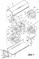
- Fig. 1 shows an example of a muffler 2 to be insulated by means of absorption members according to the invention.
- the muffler 2 comprises a muffler housing 4 in turn comprised of peripheral wall portions 6 and 8 which are welded or crimped together at their edges such as to form a peripherally closed housing shell, and of associated front wall portions 10 and 12 including an exhaust gas inlet pipe 14 and an exhaust gas outlet pipe 16, respectively.
- Exhaust gas from a combustion engine not shown here, particularly from the engine of a motor car is conveyed to the space enclosed by the peripheral wall constituted by peripheral wall portions 6 and 8 via the exhaust gas inlet pipe 14 and again discharged from muffler 2 by means of the exhaust gas outlet pipe 16 on the opposite side.
- an inner pipe assembly comprehensively shown under 18 is provided, which in an exemplary case is constituted of three inner pipes 20, 22 and 24 in parallel arrangement which are secured in their respective positions by means of three intermediate walls 26, 28 and 30 inside the inner cavity of the muffler housing 4.
- the outer circumference of intermediate walls 26, 28 and 30 has a contour conforming with the periphery of the muffler housing 4, such that the intermediate walls 26, 28 and 30 subdivide the inner cavity of the muffler housing 4 into chambers 32, 34, 36 and 38 which are peripherally insulated with respect to each other.
- the exhaust gas is initially introduced by the exhaust gas inlet pipe 14 of the front wall portions 10 into the inner pipe 24, which is peripherally closed in the range of chamber 32 (hidden from view in the drawing) and provided with a peripheral perforation 25 in the range of chambers 34 and 36.
- the perforation 25 the exhaust gas enters into chambers 34 and 36 acting as absorption chambers in a generally known manner in interaction with absorption members 40 and 42 to thereby lose part of its sound or pulsation energy.
- the exhaust gas passes from the inner pipe 24 into the chamber 38 positioned opposite the entry side and formed as a reflection chamber.
- a further part of the sound energy is annihilated as a result of reflection phenomena.
- the exhaust gas then enters into the inner pipe 22 provided at its outer periphery with a perforation 23 wherethrough in turn sound energy is annihilated inside absorption chambers 34 and 36. From the inner pipe 22 the exhaust gas then enters into reflection chamber 32 located opposite reflection chamber 38, where sound energy is again annihilated by reflection. From the reflection chamber 32 the exhaust gas flow finally enters into the inner pipe 20 entirely closed at its periphery, which is extended downstream along the last intermediate wall 26 and merges into the exhaust gas outlet pipe 16 of the muffler housing 4.
- the absorption chambers 34 and 36 are filled up with the respective absorption members 40 and 42 made up of bound mineral wool which consequently have to receive the inner pipe assembly 18 in the area of absorption chambers 34 and 36.
- the outer contour of absorption members 40 and 42 conforms with the contour of the muffler housing 4, with inner pipes 20, 22 and 24 being received in associated recesses 44, 46 and 48 of respective absorption members 40 and 42.
- a mechanically resistant, however acoustically permissive protection layer e.g. comprised of metal wool may be arranged in a generally known manner at the inner periphery of recesses 46 and 48. In the range of the recesses 44 this is not necessary in the present example as they receive the non-perforated inner pipe 20 and are therefore not exposed to stresses by the exhaust gas flowing inside inner pipe 20.
- the very arrangement of intermediate walls 26, 28 and 30 precludes axial slipping on of absorption members 40 and 42. Installation on the inner pipe assembly 18 in a lateral direction, i.e. in a radial direction instead of axially, is therefore necessary.
- absorption members 40 and 42 are constituted of respective parts 40a and 40b or 42a and 42b abutting in the installed position at their dividing lines or cut surfaces 50.
- the recess 44 for the inner pipe 20 is centrally divided by the dividing line or cut surface 50, resulting in two semicircular depressions respectively associated with parts 40a and 40b or 42a and 42b which encompass the inner pipe 20 from two sides.
- the recesses 46 and 48 in turn are designed as peripherally closed central passages receiving the inner pipes 22 and 24 entirely inside each respective part 40a and 40b or 42a and 42b.
- the recesses 46 and 48 are provided with a respective parting slit 47 or 49 extending towards the outside of respective associated parts 40a and 40b or 42a and 42b, through which the respective inner pipes 22 and 24 can pass when installing the respective parts 40a and 40b or 42a and 42b.
- the parts 40a and 40b as well as 42a and 42b, i.e. the absorption members 40 and 42 include parallel major surfaces 52 in a perpendicular direction with respect to the cut surfaces and thus basically have a board-type shape.
- the board thickness i.e. the width of absorption members 40 and 42 is limited.
- each absorption member 40 or board-type shaped section 41 thereof, respectively is represented in further detail.
- each absorption member 40 or board-type shaped section 41 thereof, respectively is pre-fabricated in the case of the depicted example to have the entire contour of absorption member 40, and the outer contour can be produced by punch-cutting.
- the recess 44 for the non-perforated inner pipe 20, which is made up of semicircular depressions of the single parts 40a and 40b, is produced by means of corresponding punching tools.
- each part 40a and 40b formed as recesses 46 and 48 together with parting slits 49 and cut surface or dividing line 50 are equally produced in a single work step by means of a corresponding punching tool.
- the dividing line 50 comprises a portion 51 wherein only a non-continuous punched cut has been produced, such that the parts 40a and 40b following their production initially remain connected to each other. Only during installation, the two material webs represented under 51a are manually destroyed in the range of portion 51 of the dividing line or cut surface 50 by bending open the dividing line 50 between parts 40a and 40b, resulting in separate parts 40a and 40b as represented in Fig. 1.
- part 40a a view of which is again represented in Fig. 3, is obtained.
- the installation of part 40a is shown in detail in Fig. 4.
- the material is bent open at the periphery of recess 46. This results in a deformation distributed more or less homogeneously over the entire peripheral range of recess 46 and thus including the entire material in this location in the absence of excessive stress peaks.
- the deformation succeeds despite the relatively great deformation path in the absence of any excessive stress peaks and thus largely of any destruction to the structure of the bound mineral wool, such that the edges of parting slit 49 resiliently return after the part 40a has been installed on the inner pipe 22 in the representation of Fig.
- FIG. 5 schematically shows production of absorption members 40 and 42 or of respective board-type shaped sections 41 herefor.
- a conventional fiberising unit not shown here such as e.g. a fiberising rotor, in cooperation with suitable gas flows generates a gas flow 202 which comprises cooling fibers and is channelled into a chute 204 where the fibers are sprayed with binding agent through nozzles 206.
- the fibers thus provided with uncured binding agent arrive at the bottom of chute 204 on a production conveyor 208 on which they are deposited under low pressure and form a mat 212 as they approach the exit 210 from the chute 204.
- Compression of mat 212 to the desired final thickness and concurrent curing of the binding agent takes place inside a tunnel furnace 214, such that the material exits from the tunnel furnace 214 having the form of a continuous board 216 with a desired height and bulk density.
- the continuous board 216 is then supplied to a punching device 218 wherein punching tools 220 in a manner known per se produce e.g. the board section 41 shown in Fig. 2 or, if the installation space has a small width, an entire absorption member 40 including all the cuts with a perpendicular orientation with respect to the major surfaces 52.
- the used punching tool 220 is provided in the area of portion 51 of the cut surface 50 including gaps 222, such that corresponding material webs 51a connecting the parts 40a and 40b remain between the cut surfaces until the time of installation. It is thereby ensured that mistakes do not occur during installation and that the respective parts are always ready at hand when they are required for installation.
Landscapes
- Engineering & Computer Science (AREA)
- Chemical & Material Sciences (AREA)
- Combustion & Propulsion (AREA)
- Mechanical Engineering (AREA)
- General Engineering & Computer Science (AREA)
- Exhaust Silencers (AREA)
- Solid-Sorbent Or Filter-Aiding Compositions (AREA)
- Soundproofing, Sound Blocking, And Sound Damping (AREA)
Abstract
Description
- Fig. 1
- is a perspective explosion view of a muffler comprising absorption members according to the invention which are made up of parts, extend in a first example over the entire width of the installation space, and are comprised in a second example of a plurality of board sections arranged in juxtaposition;
- Fig. 2
- is a perspective view of an absorption member of the invention or a board section thereof, respectively;
- Fig. 3
- shows a part of the absorption member of Fig. 2;
- Fig. 4
- shows the part of Fig. 3 in a position deformed for installation prior to mounting on the muffler;
- Fig. 5
- is a schematic view of the method for producing an absorption member or part thereof, respectively, of the invention; and
- Fig. 6
- is a schematic partial view of a punching tool for producing a non-continuous cut.
Claims (12)
- Absorption member (40, 42) made up of bound mineral woolcharacterisedfor acoustic insulation inside an exhaust muffler (2), particularly of a motor car, which includes at least three inner pipes (20, 22, 24) arranged in parallel with each other and not included in a common plane,having an outer contour which matches the periphery of the muffler housing (4) andhaving recesses (44, 46, 48) which correspond to the inner pipes (20, 22, 24) to be received,and said absorption member being constituted of parts (40a, 40b, 42a, 42b) which can be installed on said inner pipes (20, 22, 24) in a lateral direction such as to jointly form the absorption member (40, 42) receiving said inner pipes (20, 22, 24) in said recesses,by being formed as a board-type shaped article, particularly a punched member with parallel major surfaces (52),by formation of at least one of said recesses (46, 48) in at least one of said parts (40a, 40b, 42a, 42b) as a central passage at least approximately entirely closed and having a contour adapted to the periphery of an associated inner pipe (22, 24), andby a parting slit (47, 49) extending in the material of said part from said at least one recess (46, 48) formed as a central passage as far as the outside of said part (40a, 40b, 42a, 42b).
- Absorption member in accordance with claim 1, characterised in that the edge of said central passage includes a stress-reducing slit on its side opposite said parting slit (47, 49).
- Absorption member in accordance with claim 1 or 2, characterised by a binding agent content of 2% wt. dry or less.
- Absorption member in accordance with any one of claims 1 to 3, characterised by being assembled of a plurality of board-type shaped sections (41) arranged in juxtaposition.
- Absorption member in accordance with claim 4, characterised in that each of said board-type shaped sections (41) has a thickness of less than 10 cm, preferably less than 8 cm, and particularly less than 6 cm.
- Absorption member in accordance with any one of claims 1 to 5, characterised in that in the case of three inner pipes (20, 22, 24), two parts (40a, 40b and 42a, 42b) having a dividing line (50) which passes between two inner pipes (22, 24) are formed.
- Absorption member in accordance with claim 6, characterised in that said dividing line (50) intersects said third inner pipe (20) preferably in the axis thereof.
- Absorption member in accordance with any one of claims 1 to 7, characterised in that said parts (40a, 40b and 42a, 42b) are pre-fabricated to cohere to each other while being delimited from each other by a dividing line (50).
- Absorption member in accordance with claim 8, characterised in that at least one portion (50 or 51) of said dividing line is formed by a non-continuous, perforation-type punched cut.
- A part (40a, 40b, 42a, 42b) for the absorption member (40,42) as defined in claim 1, said part having at least one recess (46, 48) as a central passage at least approximately entirely closed and having a contour adapted to the periphery of an associated inner pipe (22, 24), and said part also having a parting slit (47, 49) extending in the material of said part from said recess (46, 48) formed as a central passage as far as the outside of said part (40a, 40b, 42a, 42b).
- Method for producing an absorption member (40, 42) in accordance with claim 1 or a part (40a, 40b, 42a, 42b) thereof in accordance with claim 10, respectively,
characterised by the steps ofdepositing mineral fibers (202) provided with binding agent on a production conveyor (208) and subsequently compacting and curing the resulting fiber mat (212) to produce a mineral wool board (216),and punching from said mineral wool board (216) said absorption members (40, 42) or parts (40a, 40b, 42a, 42b) thereof, respectively, including said recesses (44, 46, 48) and slits (47, 49). - Method in accordance with claim 11, characterised in that in the area of said dividing line (50) between parts (40a, 40b and 42a, 42b) pertaining to an absorption member (40, 42), a non-continuous punching tool (220) is used to produce a perforated portion (51).
Applications Claiming Priority (2)
| Application Number | Priority Date | Filing Date | Title |
|---|---|---|---|
| DE19512438 | 1995-04-03 | ||
| DE19512438A DE19512438A1 (en) | 1995-04-03 | 1995-04-03 | Mineral wool absorption part for sound absorption in an exhaust silencer, section therefor, its use and method for its production |
Publications (2)
| Publication Number | Publication Date |
|---|---|
| EP0736674A1 EP0736674A1 (en) | 1996-10-09 |
| EP0736674B1 true EP0736674B1 (en) | 2000-03-22 |
Family
ID=7758658
Family Applications (1)
| Application Number | Title | Priority Date | Filing Date |
|---|---|---|---|
| EP96105287A Expired - Lifetime EP0736674B1 (en) | 1995-04-03 | 1996-04-02 | Absorption member of mineral wool for acoustic insulation in an exhaust muffler, part therefor, its use, and method for producing it |
Country Status (7)
| Country | Link |
|---|---|
| EP (1) | EP0736674B1 (en) |
| AT (1) | ATE191059T1 (en) |
| CZ (1) | CZ90796A3 (en) |
| DE (2) | DE19512438A1 (en) |
| HU (1) | HUP9600796A3 (en) |
| PL (1) | PL313581A1 (en) |
| SI (1) | SI9600111A (en) |
Cited By (1)
| Publication number | Priority date | Publication date | Assignee | Title |
|---|---|---|---|---|
| US7278473B2 (en) | 2002-06-25 | 2007-10-09 | Behr Gmbh & Co. | Exhaust gas heat exchanger and method for the production thereof |
Families Citing this family (1)
| Publication number | Priority date | Publication date | Assignee | Title |
|---|---|---|---|---|
| CN113153506B (en) * | 2021-05-25 | 2022-09-13 | 佛吉亚(柳州)排气控制技术有限公司 | Automobile silencer structure convenient to disassemble and assemble |
Family Cites Families (4)
| Publication number | Priority date | Publication date | Assignee | Title |
|---|---|---|---|---|
| US2072961A (en) * | 1934-03-01 | 1937-03-09 | Burgess Lab Inc C F | Silencer |
| DE3826707A1 (en) * | 1988-08-05 | 1990-02-08 | Gruenzweig & Hartmann | METHOD FOR PRODUCING AN EXHAUST MUFFLER |
| DE9012260U1 (en) * | 1990-08-25 | 1990-11-08 | Mussbach Metall Hackelsberger GmbH & Co, 6730 Neustadt | Absorption moldings for motor vehicle exhaust systems |
| DE9401674U1 (en) * | 1994-02-02 | 1994-04-21 | Fa. J. Eberspächer, 73730 Esslingen | Silencer, in particular exhaust silencer, for an engine-independent vehicle heater |
-
1995
- 1995-04-03 DE DE19512438A patent/DE19512438A1/en not_active Withdrawn
-
1996
- 1996-03-27 CZ CZ96907A patent/CZ90796A3/en unknown
- 1996-03-29 HU HU9600796A patent/HUP9600796A3/en unknown
- 1996-04-02 PL PL96313581A patent/PL313581A1/en unknown
- 1996-04-02 DE DE69607229T patent/DE69607229T2/en not_active Expired - Fee Related
- 1996-04-02 AT AT96105287T patent/ATE191059T1/en not_active IP Right Cessation
- 1996-04-02 EP EP96105287A patent/EP0736674B1/en not_active Expired - Lifetime
- 1996-04-03 SI SI9600111A patent/SI9600111A/en unknown
Cited By (1)
| Publication number | Priority date | Publication date | Assignee | Title |
|---|---|---|---|---|
| US7278473B2 (en) | 2002-06-25 | 2007-10-09 | Behr Gmbh & Co. | Exhaust gas heat exchanger and method for the production thereof |
Also Published As
| Publication number | Publication date |
|---|---|
| HUP9600796A2 (en) | 1996-10-28 |
| EP0736674A1 (en) | 1996-10-09 |
| CZ90796A3 (en) | 1996-10-16 |
| ATE191059T1 (en) | 2000-04-15 |
| PL313581A1 (en) | 1996-10-14 |
| DE69607229T2 (en) | 2000-09-07 |
| DE69607229D1 (en) | 2000-04-27 |
| HU9600796D0 (en) | 1996-05-28 |
| HUP9600796A3 (en) | 2000-02-28 |
| SI9600111A (en) | 1996-10-31 |
| DE19512438A1 (en) | 1996-10-10 |
Similar Documents
| Publication | Publication Date | Title |
|---|---|---|
| JPH02191809A (en) | Manufacture of silencer | |
| KR100602747B1 (en) | Intake system, especially used as intake of internal combustion engines | |
| EP1421266B1 (en) | Muffler shell filling process, muffler filled with fibrous material and vacuum filling device | |
| CN101631941A (en) | A sound-absorbing liner with hot gas anti-icing treatment function | |
| GB2209560A (en) | Silencing exhaust duct for I C engines | |
| EP0736674A1 (en) | Absorption member of mineral wool for acoustic insulation in an exhaust muffler, part therefor, its use, and method for producing it | |
| US20090166126A1 (en) | Sound-damping air-conducting duct and method for the production of a sound-damping air-conducting duct | |
| KR100369967B1 (en) | Molded Connector | |
| CN101636575A (en) | A kind of implementation methods of noise reduction liner and the liner that obtains with the method | |
| EP0131350B1 (en) | Exhaust silencer | |
| JPH0425413B2 (en) | ||
| US20050279570A1 (en) | Method for containing an acoustical material within an assembly | |
| FI78970C (en) | Form part of binder-supplied mineral fibers for sound-dampening coating of a perforated exhaust pipe and process for producing the | |
| WO1992009988A1 (en) | Improvements in attenuators | |
| JPH0445649B2 (en) | ||
| CN202320140U (en) | Partition element | |
| EP1308608B1 (en) | Engine muffler | |
| CN1302949C (en) | Protective tube for motor vehicle | |
| CA2334123A1 (en) | Universal exhaust system for motorcycles | |
| JPH0355646B2 (en) | ||
| JP7740573B2 (en) | Engine silencer | |
| EP3541608B1 (en) | Exhaust subsystem with fiber pipe and method of forming fiber pipe | |
| JPS6332324Y2 (en) | ||
| JP6757943B2 (en) | Engine exhaust silencer | |
| DE9012260U1 (en) | Absorption moldings for motor vehicle exhaust systems |
Legal Events
| Date | Code | Title | Description |
|---|---|---|---|
| PUAI | Public reference made under article 153(3) epc to a published international application that has entered the european phase |
Free format text: ORIGINAL CODE: 0009012 |
|
| AK | Designated contracting states |
Kind code of ref document: A1 Designated state(s): AT BE CH DE DK ES FR GB IT LI NL SE |
|
| 17P | Request for examination filed |
Effective date: 19961125 |
|
| 17Q | First examination report despatched |
Effective date: 19980108 |
|
| GRAG | Despatch of communication of intention to grant |
Free format text: ORIGINAL CODE: EPIDOS AGRA |
|
| GRAG | Despatch of communication of intention to grant |
Free format text: ORIGINAL CODE: EPIDOS AGRA |
|
| GRAH | Despatch of communication of intention to grant a patent |
Free format text: ORIGINAL CODE: EPIDOS IGRA |
|
| GRAH | Despatch of communication of intention to grant a patent |
Free format text: ORIGINAL CODE: EPIDOS IGRA |
|
| GRAA | (expected) grant |
Free format text: ORIGINAL CODE: 0009210 |
|
| AK | Designated contracting states |
Kind code of ref document: B1 Designated state(s): AT BE CH DE DK ES FR GB IT LI NL SE |
|
| PG25 | Lapsed in a contracting state [announced via postgrant information from national office to epo] |
Ref country code: SE Free format text: THE PATENT HAS BEEN ANNULLED BY A DECISION OF A NATIONAL AUTHORITY Effective date: 20000322 Ref country code: NL Free format text: LAPSE BECAUSE OF FAILURE TO SUBMIT A TRANSLATION OF THE DESCRIPTION OR TO PAY THE FEE WITHIN THE PRESCRIBED TIME-LIMIT Effective date: 20000322 Ref country code: LI Free format text: LAPSE BECAUSE OF NON-PAYMENT OF DUE FEES Effective date: 20000322 Ref country code: IT Free format text: LAPSE BECAUSE OF FAILURE TO SUBMIT A TRANSLATION OF THE DESCRIPTION OR TO PAY THE FEE WITHIN THE PRE;WARNING: LAPSES OF ITALIAN PATENTS WITH EFFECTIVE DATE BEFORE 2007 MAY HAVE OCCURRED AT ANY TIME BEFORE 2007. THE CORRECT EFFECTIVE DATE MAY BE DIFFERENT FROM THE ONE RECORDED.SCRIBED TIME-LIMIT Effective date: 20000322 Ref country code: FR Free format text: LAPSE BECAUSE OF FAILURE TO SUBMIT A TRANSLATION OF THE DESCRIPTION OR TO PAY THE FEE WITHIN THE PRESCRIBED TIME-LIMIT Effective date: 20000322 Ref country code: ES Free format text: THE PATENT HAS BEEN ANNULLED BY A DECISION OF A NATIONAL AUTHORITY Effective date: 20000322 Ref country code: CH Free format text: LAPSE BECAUSE OF NON-PAYMENT OF DUE FEES Effective date: 20000322 Ref country code: BE Free format text: LAPSE BECAUSE OF FAILURE TO SUBMIT A TRANSLATION OF THE DESCRIPTION OR TO PAY THE FEE WITHIN THE PRESCRIBED TIME-LIMIT Effective date: 20000322 Ref country code: AT Free format text: LAPSE BECAUSE OF FAILURE TO SUBMIT A TRANSLATION OF THE DESCRIPTION OR TO PAY THE FEE WITHIN THE PRESCRIBED TIME-LIMIT Effective date: 20000322 |
|
| REF | Corresponds to: |
Ref document number: 191059 Country of ref document: AT Date of ref document: 20000415 Kind code of ref document: T |
|
| REG | Reference to a national code |
Ref country code: CH Ref legal event code: EP |
|
| REF | Corresponds to: |
Ref document number: 69607229 Country of ref document: DE Date of ref document: 20000427 |
|
| PG25 | Lapsed in a contracting state [announced via postgrant information from national office to epo] |
Ref country code: GB Free format text: LAPSE BECAUSE OF NON-PAYMENT OF DUE FEES Effective date: 20000622 Ref country code: DK Free format text: LAPSE BECAUSE OF FAILURE TO SUBMIT A TRANSLATION OF THE DESCRIPTION OR TO PAY THE FEE WITHIN THE PRESCRIBED TIME-LIMIT Effective date: 20000622 |
|
| EN | Fr: translation not filed | ||
| NLV1 | Nl: lapsed or annulled due to failure to fulfill the requirements of art. 29p and 29m of the patents act | ||
| REG | Reference to a national code |
Ref country code: CH Ref legal event code: PL |
|
| PLBE | No opposition filed within time limit |
Free format text: ORIGINAL CODE: 0009261 |
|
| STAA | Information on the status of an ep patent application or granted ep patent |
Free format text: STATUS: NO OPPOSITION FILED WITHIN TIME LIMIT |
|
| PG25 | Lapsed in a contracting state [announced via postgrant information from national office to epo] |
Ref country code: DE Free format text: LAPSE BECAUSE OF NON-PAYMENT OF DUE FEES Effective date: 20010201 |
|
| GBPC | Gb: european patent ceased through non-payment of renewal fee |
Effective date: 20000622 |
|
| 26N | No opposition filed |