EP0736453B1 - Beleuchtungssystem für Flugzeug - Google Patents
Beleuchtungssystem für Flugzeug Download PDFInfo
- Publication number
- EP0736453B1 EP0736453B1 EP96302424A EP96302424A EP0736453B1 EP 0736453 B1 EP0736453 B1 EP 0736453B1 EP 96302424 A EP96302424 A EP 96302424A EP 96302424 A EP96302424 A EP 96302424A EP 0736453 B1 EP0736453 B1 EP 0736453B1
- Authority
- EP
- European Patent Office
- Prior art keywords
- light source
- infra red
- voltage
- visible light
- aircraft
- Prior art date
- Legal status (The legal status is an assumption and is not a legal conclusion. Google has not performed a legal analysis and makes no representation as to the accuracy of the status listed.)
- Expired - Lifetime
Links
Images
Classifications
-
- B—PERFORMING OPERATIONS; TRANSPORTING
- B64—AIRCRAFT; AVIATION; COSMONAUTICS
- B64D—EQUIPMENT FOR FITTING IN OR TO AIRCRAFT; FLIGHT SUITS; PARACHUTES; ARRANGEMENT OR MOUNTING OF POWER PLANTS OR PROPULSION TRANSMISSIONS IN AIRCRAFT
- B64D47/00—Equipment not otherwise provided for
- B64D47/02—Arrangements or adaptations of signal or lighting devices
- B64D47/06—Arrangements or adaptations of signal or lighting devices for indicating aircraft presence
Definitions
- the present invention relates to external aircraft lighting systems, and in particular to such systems for use with night vision goggles.
- Night vision goggles are used in military aircraft.
- infra red light should be understood to include near infra red light throughout this document
- NVGs considerably enhance a pilot's ability to "see” in the dark.
- external aircraft lighting in the visible spectrum becomes (in certain contexts) unnecessary, and military aircraft can thus be operated in a covert mode in which no such external lighting is provided, making the aircraft harder to detect.
- By providing low intensity external infra red lighting it can be ensured that aircraft remain visible to each other, e.g for collision avoidance, formation flying, location and orientation, while still providing no illumination visible to the naked eye.
- an external lighting assembly for an aircraft, said assembly comprising a source of visible and infra red light and being characterised by a filter which is at least substantially transparent to visible light and allows visible light from the source to be emitted by the lighting assembly while substantially reducing emission of selected infra red frequencies, thereby preventing or reducing dazzle of night vision systems in use.
- said source of visible light is mounted in a housing having a window through which visible light is emitted by sy said visible light source, said filter being disposed in said housing between the visible light source and said window such that visible light from said visible light source can only reach said window via said filter.
- said filter is an interference type filter which selectively reflects the infra red frequencies.
- said lighting assembly further comprises electrically powered infra red emitting means.
- Said infra red emitting means may take the form of one or more infra red diodes disposed externally on said housing.
- selected infra red frequencies can be blocked by the filter and thus removed from the output of the visible light source.
- the visible light source can be made to appear dimmer to the night vision system (thereby preventing the NVG from being dazzled) or can even be made substantially invisible to the night vision system, while still giving the visible signal (that is, visible to the naked eye) required by regulations.
- the visible signal that is, visible to the naked eye
- the additional infra red emitter can be used to provide a relatively low intensity IR signal to others using night vision systems (to enable formation flying etc) without producing visible light.
- the lighting assembly is provided with voltage sensing means adapted to monitor a supply voltage to said visible light source and to connect said supply voltage to the infra-red emitting means when said supply voltage is less than a predetermined threshold.
- the single wire conventionally used to drive the source of visible light can be used to selectively energise the visible or infra red light sources, as will be explained below.
- the external lighting assembly in accordance with the first aspect is incorporated in a lighting system for an aircraft which further comprises at least one current supply cable mounted in the aircraft fuselage/wings, a coder at a cockpit end of said cable for coding power signals applied to that cable, and decoding means at an opposite, remote end of said cable for selectively energising the infra red emitting means and/or the visible light source.
- the coder enables a range of voltage levels to be selectively applied to said current supply cable and the decoder includes a voltage sensing means which is adapted to selectively couple the visible light source and/or the infra red emitting means to the current supply depending on the voltage level detected.
- the decoder is adapted to connect the infra red emitting means to the current supply only when the voltage level detected lies below a predetermined threshold.
- the coder is adapted to enable a voltage source to be connected selectively to said current supply cable in either of a forward (+) polarity or a reverse (-) polarity, the decoder comprising two diodes connected respectively to the visible light source and the infra red emitting means with opposite orientations, whereby one diode is conductive to the forward polarity supply to energise the visible light source and the other diode is conductive to the reverse polarity supply to energise the infra red emitting means.
- the coder is adapted to apply to said current supply cable a coded digital signal and the decoder is adapted to decode the latter signal and selectively connect the visible light source and/or the infra red emitting means to the current supply cable in dependence upon the coded signal.
- a filter unit adapted to be fitted to an external aircraft lighting assembly having a source of visible and infrared light disposed within a housing and a housing window through which visible light is emitted, the filter unit being adapted to partition the housing of the aircraft lighting assembly such as to separate the light source within the housing from the housing window and comprising a filter through which light from the source can reach the window, the filter being at least substantially transparent to visible light and being such as to remove or substantially remove selected infra red frequencies from the radiation emitted by the light source.
- a preferred lighting system comprises an external lighting assembly of the above described type provided with a control means, a variable voltage supply means and a conductor via which the voltage supply means is connected to the visible light source, the control means being sensitive to the voltage supplied by the voltage supply means through the conductor and being adapted to connect the infra red emitter means to the conductor to apply a drive voltage thereto only when the voltage is below a predetermined threshold, the visible light source being such as to be dimmed by voltages below the threshold so that either the visible light source or the infra red emitter can be activated.
- a single wire can be used to selectively switch on either the IR emitter or the visible light source.
- the voltage supply means is connected to a cockpit end of the conductor and the control means is disposed in the vicinity of the infra red emitter.
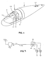
- the light illustrated in Fig. 1 comprises a substantially conventional tear drop shaped fairing 1 with a shaped, tinted forward window 3 within which is disposed a conventional light bulb 5.
- a conventional light bulb 5 Such lights are in use in existing aircraft.
- the light has been modified by insertion of a filter 7 within the forward window.
- the filter 7 comprise an arched, opaque cage 9 which is placed around the bulb 5.
- the cage 9 is penetrated by several apertures 11 which are covered by filter elements 13, and the front of the cage (which would otherwise be open) is covered by an arch shaped filter element 15.
- This construction permits the use of conventional, flat, filter elements 13,15.
- the filter elements 13 and 15 while at least substantially transparent to visible light, are at least substantially opaque to the IR wavelengths detected by NVGs, so that little or no light at these wavelengths produced by the bulb 5 is emitted by the light.
- the filter elements must be heat resistant, to withstand heat from the incandescent bulb, and are (according to the present embodiment) in the form of interference type glass filters which selectively reflect infra red, preventing heat damage.
- infra red emitter 17 eg an infra red emitting diode
- infra red emitter implies a device which can be driven to emit infra red or near infra red light while generating little or no visible light.
- the modified light Two modes of operation are made possible by the modified light. Where appropriate (eg during training exercises, when visible external light is required) the bulb 5 is illuminated.
- the modified light retains, in visible mode, all the facilities of standard lighting such as flashing and dimming.
- the bulb 5 is turned off, the IR emitter 17 is (if desired) turned on, and the light becomes visible only to those wearing NVGs.
- the present exemplary embodiment can incorporate a voltage sensitive "sniffer" circuit 40 (see Fig. 7). While the bulb 5 is connected directly to the single supply line 113d, the IR emitter 17 is connectable to the supply line 113d via detection circuitry 42 within the sniffer circuit 40.
- the sniffer circuit 40 operates as a voltage sensitive switch which opens (and so applies a voltage across the IR emitter 17) only when the applied supply voltage on the supply line 113d lies below a predetermined level of approximately 5 volts.
- the bulb 5 is designed to operate at between 50v (dim mode) and 110v (bright mode).
- the detection circuitry 42 in the sniffer circuit 40 turns the IR emitter 17 off.
- the detection circuitry 42 in the sniffer circuit 40 can be straightforwardly achieved using transistor/zener diode devices.
- the control electronics 44 provided at the cockpit end of the supply line can selectively set the supply voltage at either 5 volts or 50-110 volts and so to switch between IR (covert) lighting only and visible lighting only.
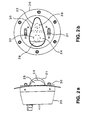
- Fig. 2 shows a further light - in this case a formation light for mounting at the upper surface of a fuselage - modified in accordance with the present invention.
- the formation light is based on a circular housing 20 on the outer surface of which is disposed a tear drop shaped fairing 22, having an opaque rear portion 24 and a transparent forward window 26.
- Components within the housing are shown in dotted lines and comprise a main bulb 28, a filter partition 30 and a re-fuelling bulb 32.
- the re-fuelling bulb 32 is used only during refuelling under visible lighting and is of no interest for present purposes.
- the main bulb 28 is used in normal flight to provide visible lighting, its light emission being filtered (to remove IR frequencies, as in the previously described embodiment) by the filter partition 30 before escaping through the forward window 26.
- the filter partition 30 can be retro-fitted to an existing light.
- Two infra red emitters 31 are provided on the housing 20 for use in covert flying, and visible and IR lighting can be switched as in the previously described embodiment.
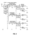
- FIG. 3 there is shown a generalised view of a modified aircraft wiring system in accordance with the present invention.
- the system can be considered to comprise three distinct sections, namely a cockpit section 110, a wing tips and/or tail fin section 112, both of which are relatively easily accessible and modifiable, and a section 114 consisting of existing wiring 113 which runs through the aircraft fuselage/wings between sections 110 and 112. It is desirable to avoid modification of the existing wiring in section 114, since this requires extensive disassembly of the aircraft.
- the system of Fig. 3 includes in the cockpit section 110 a coder unit 116 controlled by a cockpit switch 118 preferably positioned near to the cockpit lighting switch, and in the wing tips/tail fin section 112 one or more corresponding decoders 120, and also a visible light source 124 and an I.R. light source 122.
- the coder/decoder system can power and selectively activate the two exterior lights (visible/I.R.) using only one existing power wire. If necessary, further lights could even be controlled.
- Fig. 3 shows by way of example three sets of existing wiring 113a, 113b, 113c comprising respectively the existing wiring through the wing to the port wing tip, the existing wiring through the wing to the starboard wing tip and the existing wiring through the fuselage to the tail fin.
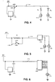
- Figs. 4 to 6 show examples of possible coding means applicable to the generalised system of Fig. 3.
- a first diode D1 is connected in series with the visible light source 124a and a second diode D2 is connected in series with a newly fitted I.R. source 122a.
- the coder at the cockpit end consists in this case of a supply inverter 116a which enables the existing cabling 113a to be supplied either with a positive or negative supply voltage. In this case, if a positive supply is selected, the visible source 124 only will be energised, and if the negative supply is selected, only the I.R. source 122a will be energised.
- Fig. 5 shows an example where the detector is a linear voltage detector 120b which responds to the magnitude of the input voltage thereto to select different loads, ie. different light sources 122b, 124b.
- the cockpit coder enables different levels of voltage to be selected for application to the existing cabling 113b. In the simple case illustrated, this is achieved by selecting either a direct connection to a +28v supply or a proportion (in this case 50%) of that supply determined by the value of a switched resistor R. In this case more than two light sources could be controlled by splitting the supply voltage further.
- Fig. 6 shows an example where a small digital signal is superimposed on the supply voltage on the existing wiring 113c by means of a digital coder 116.
- This small digital signal is picked up by a digital decoder 120c in section 112 and can supply any number of additional light sources (not shown) in addition to or in place of the existing visible source 24c.
Landscapes
- Engineering & Computer Science (AREA)
- Aviation & Aerospace Engineering (AREA)
- Circuit Arrangement For Electric Light Sources In General (AREA)
Claims (14)
- Äußere Beleuchtungsbaugruppe für ein Flugzeug, wobei die genannte Baugruppe eine Quelle für sichtbares und Infrarotlicht (5; 28) aufweist und durch einen Filter (13; 15; 30) gekennzeichnet ist, der wenigstens im wesentlichen transparent für sichtbares Licht ist und es zuläßt, daß durch die Beleuchtungsbaugruppe sichtbares Licht aus der Quelle emittiert wird, wobei im wesentlichen die Emission ausgewählter Infrarotfrequenzen verringert wird, wodurch die Blendung von Nachtsichtsystemen in Verwendung verhindert oder verringert wird.
- Äußere Beleuchtungsbaugruppe nach Anspruch 1, bei der die genannte Lichtquelle in einem Gehäuse (1) mit einem Fenster (3) angebracht ist, durch das sichtbares Licht durch die Lichtquelle emittiert wird, wobei der Filter in dem Gehäuse zwischen der Lichtquelle und dem Fenster angeordnet ist, so daß sichtbares Licht aus der Lichtquelle das Fenster nur über den Filter erreichen kann.
- Äußere Beleuchtungsbaugruppe nach Anspruch 1 oder 2, bei der der Filter ein Filter vom Störschutztyp ist, der selektiv Infrarotstrahlung reflektiert.
- Äußere Beleuchtungsbaugruppe nach einem vorhergehenden Anspruch, die einen undurchsichtigen gewölbten Käfig (9) um die Lichtquelle herum aufweist, wobei der Käfig von Öffnungen (11) durchstoßen ist, die durch flache Filterelemente (13) bedeckt sind.
- Äußere Beleuchtungsbaugruppe nach einem vorgehenden Anspruch, die weiter elektrisch betriebene Infrarotstrahlermittel (17; 31) umfaßt.
- Äußere Beleuchtungsbaugruppe nach Anspruch 5, die weiter Spannungsnachweismittel (40) aufweist, die zum Überprüfen einer Versorgungsspannung zu der Lichtquelle und zum Verbinden der Versorgungsspannung mit dem Infrarotstrahlermittel ausgeführt ist, wenn die Versorgungsspannung geringer als ein vorbestimmter Schwellenwert ist.
- Beleuchungssystem für ein Flugzeug, das eine äußere Beleuchtungsbaugruppe wie in Anspruch 5 beansprucht, wenigstens ein im Rumpf/den Flügeln des Flugzeugs angebrachtes Stromversorgungskabel (113), einen Kodierer (116) an einem Cockpitende des genannten Kabels zum Kodieren von an das Kabel angelegten Energiesignalen, und Dekodiermittel (120) an einem entgegengesetzten, entfernten Ende des Kabels zum selektiven Speisen des Infrarotstrahlermittels und/oder der Lichtquelle mit Energie aufweist.
- Beleuchtungssystem für ein Flugzeug nach Anspruch 7, bei dem der Kodierer ausgeführt ist, um die selektive Verbindung einer Spannungsquelle mit dem Stromversorgungskabel entweder in einer Vorwärts (+) - Polarität oder einer Rückwärts (-)-Polarität zu ermöglichen, wobei der Dekodierer zwei Dioden (D1, D2) aufweist, die mit der Quelle für sichtbares Licht bzw. dem Infrarotstrahlermittel mit entgegengesetzten Ausrichtungen verbunden sind, wodurch eine Diode leitend für die Versorgung der Vorwärtspolarität ist, um die Quelle für sichtbares Licht mit Energie zu speisen, und die andere Diode leitend für die Versorgung der Rückwärtspolarität ist, um das Infrarotstrahlermittel mit Energie zu speisen.
- Beleuchtungssystem für ein Flugzeug nach Anspruch 7, bei dem der Kodierer ermöglicht, daß eine Spanne von Spannungspegeln selektiv an das Stromversorgungskabel angelegt wird, und der Dekodierer ein Spannungsnachweismittel umfaßt, das ausgeführt ist, um abhängig von dem ermittelten Spannungspegel selektiv die Quelle für sichtbares Licht und/oder das Infrarotstrahlermittel mit der Stromversorgung zu koppeln.
- Beleuchtungssystem für ein Flugzeug nach Anspruch 9, bei dem der Dekodierer ausgeführt ist, um das Infrarotstrahlermittel nur dann mit der Stromversorgung zu verbinden, wenn der ermittelte Spannungspegel unter einem vorbestimmten Schwellenwert liegt.
- Beleuchtungssystem für ein Flugzeug nach Anspruch 7, bei dem der Kodierer ausgeführt ist, um dem Stromversorgungskabel ein kodiertes Digitalsignal zuzuführen, und der Dekodierer ausgeführt ist, um das letztere Signal zu decodieren und selektiv die Quelle für sichtbares Licht und/oder das Infrarotstrahlermittel abhängig von dem kodierten Signal mit dem Stromversorgungskabel zu verbinden.
- Beleuchtungssystem für ein Flugzeug, das eine wie in Anspruch 5 beanspruchte äußere Beleuchtungsbaugruppe ausgestattet mit Steuermitteln (40), einem variablen Spannungsversorgungsmittel und einem Leiter (113d) aufweist, über den das Spannungsversorgungsmittel mit der Quelle für sichtbares Licht verbunden ist, wobei das Steuermittel empfindlich für die Spannung ist, die über den Leiter durch das Spannungsversorgungsmittel zugeführt wird, und zum Verbinden des Infrarotstrahlermittels mit dem Leiter ausgeführt ist, um eine Steuerspannung nur dann an dasselbe anzulegen, wenn die Spannung unter einem vorbestimmten Schwellenwert liegt, wobei die Quelle für sichtbares Licht so eingerichtet ist, daß sie durch Spannungen unterhalb des Schwellenwertes abgeblendet wird, so daß entweder die Quelle für sichtbares Licht oder der Infrarotstrahler aktiviert werden kann.
- Filtereinheit, die ausgeführt ist, um an einer äußeren Flugzeugbeleuchtungsbaugruppe angebracht zu werden, welche eine in einem Gehäuse (1) angeordnete Quelle für sichtbares und infrarotes Licht (5, 28) und ein Gehäusefenster (13) aufweist, durch das sichtbares Licht emittiert wird, wobei die Filtereinheit ausgeführt ist, um das Gehäuse der Flugzeugbeleuchtungsbaugruppe so zu unterteilen, daß die Lichtquelle innerhalb des Gehäuses von dem Gehäusefenster getrennt wird, und einen Filter (13, 15, 30) aufweist, durch den Licht aus der Quelle das Fenster erreichen kann, wobei der Filter wenigstens teilweise durchlässig für sichtbares Licht und so ausgeführt ist, um ausgewählte Infrarotfrequenzen aus der durch die Lichtquelle emittierten Strahlung zu entfernen oder im wesentlichen zu entfernen.
- Filtereinheit nach Anspruch 13, die einen undurchsichtigen gewölbten Käfig zur Plazierung um die Lichtquelle herum aufweist, wobei der Käfig von Öffnungen durchstoßen ist, die durch flache Filterelemente bedeckt sind.
Priority Applications (1)
| Application Number | Priority Date | Filing Date | Title |
|---|---|---|---|
| DE69609106.2T DE69609106T3 (de) | 1995-04-05 | 1996-04-04 | Beleuchtungssystem für Flugzeug |
Applications Claiming Priority (4)
| Application Number | Priority Date | Filing Date | Title |
|---|---|---|---|
| GBGB9507060.3A GB9507060D0 (en) | 1995-04-05 | 1995-04-05 | Aircraft lighting systems |
| GB9507060 | 1995-04-05 | ||
| GBGB9603350.1A GB9603350D0 (en) | 1995-04-05 | 1996-02-16 | Aircraft lighting system |
| GB9603350 | 1996-02-16 |
Publications (4)
| Publication Number | Publication Date |
|---|---|
| EP0736453A2 EP0736453A2 (de) | 1996-10-09 |
| EP0736453A3 EP0736453A3 (de) | 1997-08-13 |
| EP0736453B1 true EP0736453B1 (de) | 2000-07-05 |
| EP0736453B2 EP0736453B2 (de) | 2017-07-19 |
Family
ID=26306820
Family Applications (1)
| Application Number | Title | Priority Date | Filing Date |
|---|---|---|---|
| EP96302424.5A Expired - Lifetime EP0736453B2 (de) | 1995-04-05 | 1996-04-04 | Beleuchtungssystem für Flugzeug |
Country Status (4)
| Country | Link |
|---|---|
| US (1) | US6011493A (de) |
| EP (1) | EP0736453B2 (de) |
| DE (1) | DE69609106T3 (de) |
| GB (1) | GB9603350D0 (de) |
Families Citing this family (28)
| Publication number | Priority date | Publication date | Assignee | Title |
|---|---|---|---|---|
| TR199900917T2 (xx) | 1996-11-12 | 1999-07-21 | L.F.D. Limited | Lamba |
| ITTO980674A1 (it) * | 1998-07-31 | 2000-01-31 | Finmeccanica Spa | Elicottero. |
| US6507290B1 (en) * | 2000-03-21 | 2003-01-14 | Ledtronics, Inc. | Light emitting diode cluster module capable for use as an aircraft forward position light source |
| US6963293B1 (en) * | 2000-05-11 | 2005-11-08 | Rastar Corporation | System and method of preventing aircraft wingtip ground incursion |
| GB0015559D0 (en) * | 2000-06-27 | 2000-08-16 | Oxley Dev Co Ltd | Device controller and control arrangement |
| GB0015898D0 (en) * | 2000-06-28 | 2000-08-23 | Oxley Dev Co Ltd | Light |
| US7055994B2 (en) | 2000-09-19 | 2006-06-06 | L-3 Communications Corporation | Light source assembly and methods for aircraft external lighting |
| US6559777B1 (en) * | 2000-09-19 | 2003-05-06 | L-3 Communications Corporation | Dual mode light source for aircraft external lighting |
| US6777701B1 (en) * | 2000-11-20 | 2004-08-17 | V-Gen Ltd. | Thermal radiation marker |
| EP1270409A1 (de) * | 2001-06-15 | 2003-01-02 | Flight Components AG | Antikollisionsleuchte mit Infrarotfilter für Luftfahrzeuge |
| US6846099B2 (en) | 2001-06-21 | 2005-01-25 | Honeywell International Inc. | Aircraft position light |
| CA2476234A1 (en) * | 2002-02-13 | 2003-08-21 | L-3 Communications Corporation | Light source assembly for vehicle external lighting |
| EP1336943A1 (de) * | 2002-02-15 | 2003-08-20 | Goodrich Hella Aerospace Lighting Systems GmbH | Warnlichtvorrichtung für ein Fahrzeug, insbesondere für ein Flugzeug |
| RU2205775C1 (ru) * | 2002-02-18 | 2003-06-10 | Открытое акционерное общество "Казанский вертолётный завод" | Аэронавигационная светосигнальная система вертолёта |
| US20050006954A1 (en) * | 2003-06-30 | 2005-01-13 | The Boeing Company | Aircraft secondary electric load controlling system |
| ATE385952T1 (de) * | 2004-10-11 | 2008-03-15 | Flight Components Ag | Antikollisionsleuchte für luftfahrzeuge |
| US8665138B2 (en) * | 2007-07-17 | 2014-03-04 | Laufer Wind Group Llc | Method and system for reducing light pollution |
| US7862204B2 (en) * | 2007-10-25 | 2011-01-04 | Pervaiz Lodhie | LED light |
| US7784967B2 (en) * | 2007-10-30 | 2010-08-31 | Pervaiz Lodhie | Loop LED light |
| USD580580S1 (en) | 2008-01-11 | 2008-11-11 | Pervaiz Lodhie | Circular light structure |
| USD631567S1 (en) | 2008-01-11 | 2011-01-25 | Pervaiz Lodhie | LED bulb |
| USD613886S1 (en) | 2008-06-10 | 2010-04-13 | Pervaiz Lodhie | LED light module with cutouts |
| USD613885S1 (en) | 2008-06-10 | 2010-04-13 | Pervaiz Lodhie | Two-stage LED light module |
| USD614318S1 (en) | 2008-06-10 | 2010-04-20 | Pervaiz Lodhie | LED light module |
| DE502008003115D1 (de) * | 2008-08-22 | 2011-05-19 | Goodrich Lighting Systems Gmbh | Navigationsbeleuchtungsvorrichtung für ein Luftfahrzeug, insbesondere Militärflugzeug |
| US8264377B2 (en) | 2009-03-02 | 2012-09-11 | Griffith Gregory M | Aircraft collision avoidance system |
| USD774583S1 (en) * | 2013-03-15 | 2016-12-20 | Rosemount Aerospace Inc. | Camera housing |
| US11682313B2 (en) | 2021-03-17 | 2023-06-20 | Gregory M. Griffith | Sensor assembly for use in association with aircraft collision avoidance system and method of using the same |
Family Cites Families (20)
| Publication number | Priority date | Publication date | Assignee | Title |
|---|---|---|---|---|
| GB834087A (en) † | 1957-09-23 | 1960-05-04 | Gen Electric Co Ltd | Improvements in or relating to electric incandescent filament lamps |
| BE786876A (fr) * | 1971-07-29 | 1973-01-29 | Westinghouse Electric Corp | Dispositif d'alimentation sequentielle en energie electrique |
| NL7405071A (nl) † | 1974-04-16 | 1975-10-20 | Philips Nv | Gloeilamp met infrarood filter. |
| US3978342A (en) * | 1975-04-07 | 1976-08-31 | Xerox Corporation | Dual mode radiation transmitting apparatus |
| US4011541A (en) † | 1975-06-20 | 1977-03-08 | Fabry Lloyd W | Single wire system with delay switching circuit for selective control of navigation and strobe lights |
| NL8005971A (nl) † | 1980-10-31 | 1982-05-17 | Havema Bureau Voor Telekommuni | Eendraads - universeel - besturingssysteem. |
| NL8201481A (nl) † | 1982-04-07 | 1983-11-01 | Moban Bv | Systeem voor het elektrisch voeden en schakelen van een aantal stroomverbruikende apparaten. |
| US4495549A (en) * | 1982-09-28 | 1985-01-22 | The Boeing Company | Infrared radiation filter lens for aircraft lights |
| US4554544A (en) * | 1983-09-26 | 1985-11-19 | The United States Of America As Represented By The Secretary Of The Air Force | Diffuse incandescent runway marker light apparatus for overt/covert operation |
| US4580196A (en) † | 1985-01-04 | 1986-04-01 | The United States Of America As Represented By The Secretary Of The Air Force | Night vision compatible illumination for vehicle crewmember workspace |
| SE462698B (sv) † | 1988-10-07 | 1990-08-13 | Swedish Airport Technology Han | Faeltljusanlaeggning foer flygplats |
| US4951046A (en) * | 1988-11-17 | 1990-08-21 | Cooper Industries, Inc. | Runway lighting system |
| US4912334A (en) * | 1988-12-08 | 1990-03-27 | Systems Research Laboratories, Inc. | Infrared aircraft beacon light |
| DE69034065T2 (de) * | 1989-08-15 | 2004-01-22 | Mishomis Pty. Ltd., Pacoe Vale | Schaltungsanordnungen |
| US5031080A (en) † | 1990-05-24 | 1991-07-09 | Gulton Industries, Inc. | Portable cockpit light assembly |
| US5282121A (en) † | 1991-04-30 | 1994-01-25 | Vari-Lite, Inc. | High intensity lighting projectors |
| US5225828A (en) † | 1991-05-01 | 1993-07-06 | Test Systems, Inc. | Infrared identification beacon |
| DE4117289C2 (de) * | 1991-05-27 | 2000-08-10 | Hella Kg Hueck & Co | Lichtblitzwarneinrichtung für Flugzeuge |
| US5293304A (en) * | 1992-06-08 | 1994-03-08 | Godfrey Engineering | Dual mode anticollision/recognition lamp for aircraft |
| US5587784A (en) * | 1995-06-16 | 1996-12-24 | Hughes Electronics | Multispectral-staring sensor |
-
1996
- 1996-02-16 GB GBGB9603350.1A patent/GB9603350D0/en active Pending
- 1996-04-04 DE DE69609106.2T patent/DE69609106T3/de not_active Expired - Lifetime
- 1996-04-04 EP EP96302424.5A patent/EP0736453B2/de not_active Expired - Lifetime
- 1996-04-04 US US08/628,011 patent/US6011493A/en not_active Expired - Lifetime
Also Published As
| Publication number | Publication date |
|---|---|
| EP0736453A3 (de) | 1997-08-13 |
| EP0736453B2 (de) | 2017-07-19 |
| DE69609106T2 (de) | 2000-11-16 |
| DE69609106D1 (de) | 2000-08-10 |
| EP0736453A2 (de) | 1996-10-09 |
| US6011493A (en) | 2000-01-04 |
| DE69609106T3 (de) | 2018-03-08 |
| GB9603350D0 (en) | 1996-04-17 |
Similar Documents
| Publication | Publication Date | Title |
|---|---|---|
| EP0736453B1 (de) | Beleuchtungssystem für Flugzeug | |
| US6531669B1 (en) | Method and system for illuminating a mechanical rotary push-button switch | |
| EP2906472B1 (de) | Visuelle signalgebung eines flugzeugs | |
| US7663506B2 (en) | Dual mode pilot director light utilizing visible and infrared light emitting diodes (LEDS) | |
| US4633376A (en) | Advanced fuel receptacle lighting system for aerial refueling | |
| US10919644B2 (en) | Multi-mode aircraft navigation light and aircraft comprising the same | |
| US5793164A (en) | Low intensity aircraft rotor tip illumination | |
| US6559777B1 (en) | Dual mode light source for aircraft external lighting | |
| US5381312A (en) | Aircraft illumination device | |
| WO2005044663A1 (en) | Pilot director light utilizing light emitting diode (led) technology | |
| EP3812283B1 (de) | Flugzeugbildprojektor für aussenbereich | |
| US20020145533A1 (en) | High intensity flashing light | |
| US7168828B2 (en) | Multicolored LED vehicle interior light | |
| HK1260203A1 (en) | Methods of treating cancer with interferon | |
| EP0301563B1 (de) | Nachtsichtbrillen-kompatible Alarm-Anzeige | |
| US6483258B2 (en) | Infrared fiber optic light | |
| US9788399B1 (en) | System and method for flight deck laser flash mitigation | |
| EP4682060A1 (de) | Kombiniertes flugzeugnavigations- und kollisionsschutzlichtsystem, flugzeug und verfahren zum betrieb eines kombinierten flugzeugnavigations- und kollisionsschutzlichtsystems | |
| US20250242941A1 (en) | Aircraft navigation light and aircraft comprising the same | |
| RU2045764C1 (ru) | Устройство для обнаружения обледенения летательного аппарата | |
| KR0118828Y1 (ko) | 택시용 빈차표시장치 |
Legal Events
| Date | Code | Title | Description |
|---|---|---|---|
| PUAI | Public reference made under article 153(3) epc to a published international application that has entered the european phase |
Free format text: ORIGINAL CODE: 0009012 |
|
| AK | Designated contracting states |
Kind code of ref document: A2 Designated state(s): DE FR GB |
|
| PUAL | Search report despatched |
Free format text: ORIGINAL CODE: 0009013 |
|
| AK | Designated contracting states |
Kind code of ref document: A3 Designated state(s): DE FR GB |
|
| 17P | Request for examination filed |
Effective date: 19970726 |
|
| 17Q | First examination report despatched |
Effective date: 19980825 |
|
| GRAG | Despatch of communication of intention to grant |
Free format text: ORIGINAL CODE: EPIDOS AGRA |
|
| GRAG | Despatch of communication of intention to grant |
Free format text: ORIGINAL CODE: EPIDOS AGRA |
|
| GRAH | Despatch of communication of intention to grant a patent |
Free format text: ORIGINAL CODE: EPIDOS IGRA |
|
| GRAH | Despatch of communication of intention to grant a patent |
Free format text: ORIGINAL CODE: EPIDOS IGRA |
|
| GRAH | Despatch of communication of intention to grant a patent |
Free format text: ORIGINAL CODE: EPIDOS IGRA |
|
| GRAA | (expected) grant |
Free format text: ORIGINAL CODE: 0009210 |
|
| AK | Designated contracting states |
Kind code of ref document: B1 Designated state(s): DE FR GB |
|
| REF | Corresponds to: |
Ref document number: 69609106 Country of ref document: DE Date of ref document: 20000810 |
|
| ET | Fr: translation filed | ||
| PLBQ | Unpublished change to opponent data |
Free format text: ORIGINAL CODE: EPIDOS OPPO |
|
| PLBI | Opposition filed |
Free format text: ORIGINAL CODE: 0009260 |
|
| PLBF | Reply of patent proprietor to notice(s) of opposition |
Free format text: ORIGINAL CODE: EPIDOS OBSO |
|
| 26 | Opposition filed |
Opponent name: LFD LIMITED Effective date: 20010404 |
|
| PLBF | Reply of patent proprietor to notice(s) of opposition |
Free format text: ORIGINAL CODE: EPIDOS OBSO |
|
| PLBF | Reply of patent proprietor to notice(s) of opposition |
Free format text: ORIGINAL CODE: EPIDOS OBSO |
|
| REG | Reference to a national code |
Ref country code: GB Ref legal event code: IF02 |
|
| RDAF | Communication despatched that patent is revoked |
Free format text: ORIGINAL CODE: EPIDOSNREV1 |
|
| APBP | Date of receipt of notice of appeal recorded |
Free format text: ORIGINAL CODE: EPIDOSNNOA2O |
|
| APBQ | Date of receipt of statement of grounds of appeal recorded |
Free format text: ORIGINAL CODE: EPIDOSNNOA3O |
|
| APAA | Appeal reference recorded |
Free format text: ORIGINAL CODE: EPIDOS REFN |
|
| APAH | Appeal reference modified |
Free format text: ORIGINAL CODE: EPIDOSCREFNO |
|
| APBU | Appeal procedure closed |
Free format text: ORIGINAL CODE: EPIDOSNNOA9O |
|
| PLAB | Opposition data, opponent's data or that of the opponent's representative modified |
Free format text: ORIGINAL CODE: 0009299OPPO |
|
| R26 | Opposition filed (corrected) |
Opponent name: LFD LIMITED Effective date: 20010404 |
|
| REG | Reference to a national code |
Ref country code: FR Ref legal event code: PLFP Year of fee payment: 20 |
|
| PLAB | Opposition data, opponent's data or that of the opponent's representative modified |
Free format text: ORIGINAL CODE: 0009299OPPO |
|
| R26 | Opposition filed (corrected) |
Opponent name: LFD LIMITED Effective date: 20010404 |
|
| PGFP | Annual fee paid to national office [announced via postgrant information from national office to epo] |
Ref country code: DE Payment date: 20150331 Year of fee payment: 20 Ref country code: GB Payment date: 20150401 Year of fee payment: 20 |
|
| PGFP | Annual fee paid to national office [announced via postgrant information from national office to epo] |
Ref country code: FR Payment date: 20150408 Year of fee payment: 20 |
|
| PLAB | Opposition data, opponent's data or that of the opponent's representative modified |
Free format text: ORIGINAL CODE: 0009299OPPO |
|
| R26 | Opposition filed (corrected) |
Opponent name: LFD LIMITED Effective date: 20010404 |
|
| PLAY | Examination report in opposition despatched + time limit |
Free format text: ORIGINAL CODE: EPIDOSNORE2 |
|
| REG | Reference to a national code |
Ref country code: DE Ref legal event code: R071 Ref document number: 69609106 Country of ref document: DE |
|
| REG | Reference to a national code |
Ref country code: GB Ref legal event code: PE20 Expiry date: 20160403 |
|
| PLBC | Reply to examination report in opposition received |
Free format text: ORIGINAL CODE: EPIDOSNORE3 |
|
| PG25 | Lapsed in a contracting state [announced via postgrant information from national office to epo] |
Ref country code: GB Free format text: LAPSE BECAUSE OF EXPIRATION OF PROTECTION Effective date: 20160403 |
|
| PUAH | Patent maintained in amended form |
Free format text: ORIGINAL CODE: 0009272 |
|
| STAA | Information on the status of an ep patent application or granted ep patent |
Free format text: STATUS: PATENT MAINTAINED AS AMENDED |
|
| 27A | Patent maintained in amended form |
Effective date: 20170719 |
|
| AK | Designated contracting states |
Kind code of ref document: B2 Designated state(s): DE FR GB |
|
| REG | Reference to a national code |
Ref country code: DE Ref legal event code: R102 Ref document number: 69609106 Country of ref document: DE |
|
| RDAF | Communication despatched that patent is revoked |
Free format text: ORIGINAL CODE: EPIDOSNREV1 |
|
| RDAE | Information deleted related to despatch of communication that patent is revoked |
Free format text: ORIGINAL CODE: EPIDOSDREV1 |