EP0735664B1 - Angle control system for a switched reluctance drive utilizing a high frequency clock - Google Patents
Angle control system for a switched reluctance drive utilizing a high frequency clock Download PDFInfo
- Publication number
- EP0735664B1 EP0735664B1 EP96302189A EP96302189A EP0735664B1 EP 0735664 B1 EP0735664 B1 EP 0735664B1 EP 96302189 A EP96302189 A EP 96302189A EP 96302189 A EP96302189 A EP 96302189A EP 0735664 B1 EP0735664 B1 EP 0735664B1
- Authority
- EP
- European Patent Office
- Prior art keywords
- output
- counter
- clock
- output signals
- sensors
- Prior art date
- Legal status (The legal status is an assumption and is not a legal conclusion. Google has not performed a legal analysis and makes no representation as to the accuracy of the status listed.)
- Expired - Lifetime
Links
Images


Classifications
-
- H—ELECTRICITY
- H02—GENERATION; CONVERSION OR DISTRIBUTION OF ELECTRIC POWER
- H02P—CONTROL OR REGULATION OF ELECTRIC MOTORS, ELECTRIC GENERATORS OR DYNAMO-ELECTRIC CONVERTERS; CONTROLLING TRANSFORMERS, REACTORS OR CHOKE COILS
- H02P6/00—Arrangements for controlling synchronous motors or other dynamo-electric motors using electronic commutation dependent on the rotor position; Electronic commutators therefor
- H02P6/14—Electronic commutators
- H02P6/16—Circuit arrangements for detecting position
-
- H—ELECTRICITY
- H02—GENERATION; CONVERSION OR DISTRIBUTION OF ELECTRIC POWER
- H02P—CONTROL OR REGULATION OF ELECTRIC MOTORS, ELECTRIC GENERATORS OR DYNAMO-ELECTRIC CONVERTERS; CONTROLLING TRANSFORMERS, REACTORS OR CHOKE COILS
- H02P25/00—Arrangements or methods for the control of AC motors characterised by the kind of AC motor or by structural details
- H02P25/02—Arrangements or methods for the control of AC motors characterised by the kind of AC motor or by structural details characterised by the kind of motor
- H02P25/08—Reluctance motors
- H02P25/092—Converters specially adapted for controlling reluctance motors
- H02P25/0925—Converters specially adapted for controlling reluctance motors wherein the converter comprises only one switch per phase
Definitions
- the present invention generally relates to a control system and, in particular, to a control system for use in a switched reluctance drive.
- a reluctance machine can be an electric motor in which torque is produced by the tendency of its movable part to move into a position where the reluctance of a magnetic circuit is minimized, i.e. the inductance of the exciting winding is maximized.
- reluctance machine In one type of reluctance machine the energisation of the phase windings occurs at a controlled frequency. These machines may be operated as a motor or a generator. They are generally referred to as synchronous reluctance motors.
- circuitry is provided for detecting the angular position of the rotor and energizing the phase windings as a function of the rotor's position.
- This second type of reluctance machine may also be a motor or a generator and such machines are generally known as switched reluctance machines.
- the present invention is generally applicable to switched reluctance machines, including switched reluctance machines operating as motors or generators.
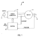
- FIG. 1 shows the principal components of a switched reluctance drive system 10 for a switched reluctance machine operating as a motor.
- the input DC power supply 11 can be either a battery or rectified and filtered AC mains.
- the DC voltage provided by the power supply 11 is switched across the phase windings of the motor 12 by a power converter 13 under the control of the electronic control unit 14.
- the switching must be correctly synchronized to the angle of rotation of the rotor for proper operation of the drive 10.
- a rotor position detector 15 is typically employed to supply signals corresponding to the angular position of the rotor.
- the output of the rotor position detector 15 may also be used to generate a speed feedback signal.
- the rotor position detector 15 may take many forms.
- the rotor position detector 15 can comprise a rotor position transducer that provides output signals that change state each time the rotor rotates to a position where a different switching arrangement of the devices in the power converter 13 is required.
- the rotor position detector 15 can comprise a relative position encoder that provides a clock pulse (or similar signal) each time the rotor rotates through a preselected angle.
- the rotor position detector 15 comprises a rotor position transducer
- failure of the rotor position transducer circuitry to properly provide output signals representative of the angular position of the rotor can seriously degrade the performance or, in the worst case, render the motor inoperable.
- a controller 14 attempting to control a machine based on faulty rotor position transducer outputs could potentially damage both the machine and the remainder of the control circuitry.
- Figure 2 generally shows a rotor pole 20 approaching a stator pole 21 according to arrow 22. As illustrated in Figure 2, a portion of a complete phase winding 23 is wound around the stator pole 21. As discussed above, when the portion of the phase winding 23 around stator pole 21 is energised, a force will be exerted on the rotor tending to pull rotor pole 20 into alignment with stator pole 21.
- Figure 3 generally shows the switching circuitry in power converter 13 that controls the energisation of the portion of the phase winding 23 around stator pole 21.
- phase winding 23 is coupled to the source of DC power and the phase winding is energised.
- the phase winding is energised to effect the rotation of the rotor as follows: At a first angular position of the rotor (called the turn-ON angle), the controller 14 provides switching signals to turn ON both switching devices 31 and 32. When the switching devices 31 and 32 are ON the phase winding is coupled to the DC bus which causes an increasing magnetic flux to be established in the motor. It is this magnetic flux pulling on the rotor poles that produces the motor torque. As the magnetic flux in the machine increases, electric current flows from the DC supply provided by the DC bus through the switches 31 and 32 and through the phase winding 23. In some controllers, current feedback is employed and the magnitude of the phase current is controlled by chopping the current by switching one or both of switching devices 31 and/or 32 on and off rapidly.
- the phase winding remains connected to the DC bus lines (or connected with chopping if chopping is employed) until the rotor rotates such that it reaches what is referred to as the rotor "freewheeling angle.”
- the freewheeling angle When the rotor reaches an angular position corresponding to the freewheeling angle (position 24 in Figure 2) one of the switches, for example 31, is turned OFF. Consequently, the current flowing through the phase winding will continue to flow, but will now flow through only one of the switches (in this example 32) and through only one of the return diodes (in this example 34).
- the freewheeling period there is little voltage differential across the phase winding, and the flux remains substantially constant.
- the motor system remains in this freewheeling condition until the rotor rotates to an angular position known as the "turn-OFF" angle (represented by position 25 in Figure 2).
- the turn-OFF angle represented by position 25 in Figure 2.
- both switches 31 and 32 are turned-OFF and the current in phase winding 23 begins to flow through diodes 33 and 34.
- the diodes 33 and 34 then apply the DC voltage from the DC bus in the opposite sense, causing the magnetic flux in the machine (and therefore the phase current) to decrease.
- phase windings in a switched reluctance motor depends heavily on accurately detecting the angular position of the rotor.
- Known encoder systems for switched reluctance drives are often limited because of the costly electronics required to rapidly process digital signals provided by an incremental position encoder such that the phase energisation occurs at the appropriate times.
- an incremental position encoder may be used that provides a relatively large number of digital clock pulses each complete revolution of the rotor.
- it is often difficult and expensive to process the large number of digital pulses provided by the incremental encoder to properly synchronize the energisation of the phase windings with the angular position of the rotor.
- EP-A-0534761 discloses a controller for a switched reluctance machine in which an encoder output is used to derive a clock signal and rotor position information for a firing angle controller.
- the present invention extends to a low cost, efficient, control system for a switched reluctance drive that generates a high resolution incremental pulse train from a position encoder.
- a circuit for using this control system to generate a high resolution, position signal which can be used to control the firing signals for a switched reluctance drive is disclosed.
- This control system allows for cost-effective control of a switched reluctance drive without the necessity of a fast microprocessor.
- the present invention comprises an improved control system and position encoder for controlling the operation of a switched reluctance machine as illustrated generally in Figure 4.
- the system comprises a controller 40 that receives signals corresponding to the angular position of the rotor from rotor position encoder 42. In response to the signals from encoder 42, the controller 40 generates switching signals (or firing signals) that determine the switching state of the power switching devices (not illustrated in Figure 4) that control energisation of the phase windings.
- the signals provided by encoder 42 to the controller 40 comprise two sets: a first set 42a and a second set 42b.
- the signals that comprise the first set 42a are of a first resolution that corresponds to the absolute position of the rotor in that the signals from set 42a may be used to define the actual rotor position within any span of 360 electrical degrees.
- the signals that comprise the second set 42b are of a second resolution that corresponds to the incremental position in that the signals that comprise set 42b provide an integral number of pulses per revolution which indicate the relative movement of the rotor but give no indication of its absolute position.
- the resolution of the first set is less than the resolution of the second set and the output signals from encoder 42 that comprise the first and second sets 42a-b comprise a series of digital pulses.
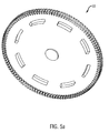
- Figures 5a-5c illustrate in greater detail the construction of encoder 42.
- the encoder 42 comprises a cup-vane 50 and sensors 51a, 51b and 51c and 52a and 52b.
- Figure 5a provides a perspective view of a cup-vane 50.
- Figures 5b and 5c illustrate cup-vane 50 in greater detail and show the positioning of sensors 51a-c and 52a-b in accordance with the present invention.
- cup-vane 50 is a dual resolution cup-vane that includes two sets of teeth 53 and 56.
- the first set of teeth 53 includes eight projecting teeth 53a-h that define eight light blocking regions corresponding to teeth 53a-h (referred to herein as "mark” regions) and eight light transmissive regions 54a-h (referred to as "space” regions).
- the teeth 53a-h are all of the same width and are sized such that the angular extent of the mark regions is substantially equal to the angular extent of the space regions.
- Figures 5b and 5c illustrate how the first set of teeth 53 may be used to provide a digital encoder of a first resolution that provides signals indicative of the absolute position of the rotor relative to the stator.
- three sensors 51a-51c are used in conjunction with the cup-vane 50 to provide the first set of digital signals.
- the three sensors 51a-51c comprise slotted optical sensors that are positioned substantially 15° degrees apart as is illustrated in Figure 5c.
- the optical sensors 51a-51c are further positioned such that they receive the eight teeth 53a-h.
- each of the three sensors 51a-51b provides a digital signal of a first logic level (e.g., logic "1") when one of the teeth 53a-h is in the slot associated with that sensor and provides a digital signal of a second logic level (e.g., logic "0") when the slot associated with that sensor is empty. Accordingly, as the teeth 53a-h rotate past the sensors 51a-51c, the outputs from the sensors together provide an indication of the absolute position of the rotor.
- a first logic level e.g., logic "1”
- a second logic level e.g., logic "0”
- the cup-vane 50 also includes a second set of teeth 56.
- the second set of teeth 56 comprises one-hundred and twenty teeth of equal width that are sized to provide one-hundred and twenty light blocking regions (referred to as "mark” regions”) and one-hundred twenty light transmissive regions (referred to as "space” regions).
- Figures 5b and 5c illustrate how the second set of teeth 56 may be used to provide a digital encoder of a second resolution that provides signals indicative of the incremental position of the rotor.
- two sensors 52a and 52b are used in conjunction with the cup-vane 50 to provide the second set of digital signals.
- the two sensors 52a-52b comprise slotted optical sensors that are positioned substantially 0.75° degrees apart as is illustrated in Figure 5c.
- the optical sensors 52a-52b are further positioned to receive the one-hundred and twenty teeth that comprise the second set of teeth 56.
- the sensors 52a and 52b operate in a manner similar to that of sensors 51a-51c described above.
- the position of one sensor on a PCD can be varied by one or more mark/space pitches without changing the timing of the waveforms produced by the sensors.
- a cup-vane be used or that the vane define light blocking and light transmissive portions.
- Other types of vanes and sensors could be used.
- the vane could be constructed of magnetic mark regions and non-magnetic space regions and the sensors could comprise Hall-effect devices.
- the vane could comprise teeth of ferromagnetic material and the sensors could each be a form of reluctance sensor.
- Other means of deriving the digital signals include regions of capacitance of inductance that vary and a suitable sensor to detect the changes.
- the present invention is not limited to the specific encoder illustrated in Figures 5a-5c but can apply to other encoders that produce a first set of signals of a first resolution. It is also applicable to encoders that additionally produce a second set of signals of a second resolution.
- the controller 40 of the present invention receives the two sets of output signals from encoder 42 and utilizes those signals to control the switching of power devices to control the energisation of the phase windings of a switched reluctance machine.
- the second set of digital output signals 42b from encoder 42 is provided to a frequency multiplier 44.
- Frequency multiplier 44 receives the second set of signals of the second resolution from encoder 42 and generates a high frequency clock signal (HF clock) that is used by angle controller 46 to control energisation of the phase windings of the machine.
- HF clock high frequency clock signal
- Figures 6a-6b provide examples of circuitry that may be used to implement the frequency multiplier 44 of Figure 4.
- Figure 6a illustrates circuitry that may be used when the second set of signals from encoder 42b is provided to frequency multiplier 44.
- Figure 6b illustrates circuitry that may be used when the first set of signals 42a from encoder 42 is provided to frequency multiplier 44.
- the second set of digital signals 42b is applied to an increment detector 60 that monitors the signals from sensors 52a and 52b and produces a signal that changes state when the rotor has rotated a predetermined high resolution increment of rotation.
- an increment detector 60 comprises an exclusive OR (XOR) gate.
- the output from increment detector 60 is a series of clock pulses where each clock pulse corresponds to a high resolution increment of rotation of the rotor.
- the series of clock pulses from increment detector 60 is applied to the Reset input of an eight bit up-counter 61. Accordingly, up-counter 61 receives the series of digital pulses derived from sensors 52a and 52b that consists of a predetermined number of pulses for each complete rotation of the rotor.
- the clock input of eight bit up-counter 61 is coupled to the system clock through a ⁇ N divider 63, where N is an integer, having the value 4 in this example.
- the system clock may have a frequency that is very high with respect to the frequency of the digital pulses that comprise the second set of digital signals provided by encoder 42.
- the up-counter 61 is reset each time a rising or falling edge of a pulse occurs in the second set of digital signals provided by encoder 42.
- the up-counter 61 will then count up in response to the divided system clock to provide a clocked output that corresponds to the angular speed of the rotor.
- the counter 61 will be reset relatively infrequently and thus the maximum count of counter 61 will be relatively high. If the angular speed of the rotor increases to a second speed, counter 61 will be reset on a more frequent basis and thus the maximum output of counter 61 will be relatively low.
- the output of counter 61 will be an eight bit maximum count value that corresponds inversely to the speed of the motor.
- the maximum output of the counter 61 may be provided to the programmable divider 62 in response to a pulse in the second set of digital signals provided by encoder 42.
- the eight-bit digital output from up-counter 61 is applied to the control input C of a programmable divider 62.
- Programmable divider 62 receives as its Clock input the system clock.
- programmable divider 62 is of standard construction and provides an output clock signal that has a frequency that is a fraction of the frequency of the signal applied at its Clock.
- the programmable divider is of the type where the output clock frequency is equal to the input clock frequency divided by the number represented by the eight-bit digital word received at the Control input.
- the programmable divider 62 provides a high frequency digital clock signal (HF clock) that has a frequency that varies proportionally with the frequency of the digital pulses that comprise the second set of signals from encoder 42. Since the frequency of the digital pulses that comprise the second set of signals from encoder 42 varies proportionally with the speed of the motor, the HF clock signal has a frequency that varies proportionally with the speed of the motor.
- HF clock high frequency digital clock signal
- the number of bits of the up-counter 61 may be increased accordingly.
- Figure 6b illustrates circuitry for implementing frequency multiplier 44 when the first set of signals 42a from encoder 42 is provided to the frequency multiplier 44.
- the circuitry of Figure 6b operates in a manner similar to that described above with respect to Figure 6a with the exception that the counter 61 is reset each time the rotor rotates through an increment of rotation as reflected by signals 42a.
- Three-input exclusive gate 64 receives the signals 42a and provides an output signal which changes state each time any one of the signals 42a changes state.
- the high resolution pulse train 42b from encoder 42 is unnecessary for a functioning drive.
- a simple RPT providing only one pulse train, could be used.
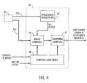
- the HF clock signal from the frequency multiplier 44 is applied to an angle control circuit 46 and a chopping control circuit 47.
- the angle control circuit 46 and chopping control circuit 47 respond to the HF clock and to the signals from encoder 42 to provide switching signals for the power devices.
- the chopping controller 47 may be used at relatively low angular speeds when chopping methods are effective for controlling the current in the phase windings, and angle controller 46 may be employed when the speed of the machine is relatively high and chopping control is ineffective.
- the angle controller 46 and chopping controller 47 receive digital rotor position signals derived from encoder 42 and compare the rotor position signals from the encoder 42 with signals corresponding to turn-ON and turn-OFF angles for the desired operating conditions.
- a switching signal is generated for the appropriate power device to energize the appropriate phase winding.
- the appropriate controller When the rotor position signals derived from encoder 42 indicate that the rotor is at the position corresponding to the turn-OFF angle, the appropriate controller generates a switching signal to turn off the appropriate switching device and de-energize the appropriate phase, winding. If chopping control is used, the controller 47 may generate chopping signals between the period defined by the turn-ON and turn-OFF angles to control the current in the phase winding.
- the turn-ON and turn-OFF information is provided by a control law table 48 that includes as its input signals representing the torque-demand and the actual speed of the machine.
- the control law table 48 may comprise a look up table that includes a pre-interpolated matrix in an EPROM containing appropriate turn-ON and turn-OFF data for several speed/torque-demand combinations. This turn-ON and turn-OFF data may be empirically derived or calculated.
- the control law table 48 comprises a sparse matrix and a microprocessor or ASIC is used to calculate the appropriate turn-ON and turn-OFF angles in real time.
- Figure 7a generally illustrates an example of the circuitry that may be used to implement the angle controller 46 of Figure 4.
- angle controller 46 may comprise an eight-bit up counter 70 that receives as its Clock input the HF clock signals discussed above in connection with Figure 6.
- the HF clock signal comprises a series of clock pulses that occur at a frequency that is proportional to the angular speed of the rotor.
- the Reset input of up-counter 70 is coupled to receive at least one signal from the first set of signals which, in the embodiment of Figure 7a is the pulse train from sensor 51a.
- the eight-bit counter 70 is reset each time an edge occurs in the output of pulse, train 51a.
- the up-counter 70 is reset on each rising edge, although embodiments are envisioned where counter 70 is reset on a falling edge. Because the counter 70 is reset at a point corresponding to an absolute position of a rotor pole relative to a stator pole, and because the counter 70 is clocked with an HF clock signal that varies in proportion to the speed of the rotor, the running output of up-counter 70 will be a digital word that increases over time, where the value of the digital word corresponds to the position of the rotor. This is illustrated generally by the Angle Control Ramp signal of Figure 7b.
- the output of the up-counter 70 is represented by the Angle Control Ramp.
- counter 70 will receive a rising edge of signal 51a. This rising edge will reset counter 70 causing its output to drop to zero. As discussed above, the occurrence of this rising edge indicates that a rotor pole has reached an absolute position relative to a stator pole.
- counter 70 After counter 70 is reset, its output will increase in response to each HF clock pulse until the next occurrence of a rising edge from pulse train 51a at time T 4 . Because the HF clock pulse occurs at a rate that is proportional to the speed of the rotor, the output of the counter 70 will correspond to the position of the rotor.
- the digital output from counter 70 may be used to generate switching signals, or firing signals, to control the power devices to energize or de-energize the phase windings of interest.
- an eight-bit comparator 72 is used to sense when the rotor has reached the turn-ON angle such that the appropriate switching device can be turned on.
- comparator 72 receives at its A input an eight-bit word from control law table 48 corresponding to the desired turn-ON point.
- Comparator 72 receives at its B input the running output from counter 70.
- comparator 72 provides a logic high output whenever its A input exceeds its B input.
- the output of comparator 72 will be a logic high ("1") whenever the signal corresponding to the desired turn-ON angle exceeds the running output of counter 70 and logic low ("0") at all other times.
- This signal is inverted by an inverter to provide a digital signal that is logic high whenever the running output of counter 70 exceeds the signal representing the turn-ON angle.
- comparator 74 receives at its A input a digital word from control law table 48 corresponding the desired turn-OFF angle and at its B input the running output of counter 70. Like comparator 72, comparator 74 produces an output signal that is logic high ("1") whenever the word at its A input exceeds the word at its B input. Accordingly, comparator 74 will produce a digital signal that is logic low (0) whenever the output from counter 70 exceeds the signal corresponding to the turn-OFF angle.
- AND gate 75 will provide a digital signal that is logic high only when the running output from counter 70 is greater than the signal representing the turn-ON angle and less than the signal representing the turn-OFF angle. This output signal from AND gate 75 can then be used to control the energisation of an appropriate phase winding by circuitry not illustrated in Figure 7a.
- the general operation of comparators 72 and 74 and AND gate 75 is illustrated in Figure 7b where the Output from AND Gate 75 represents a series of pulses that can be used to control energisation of the machine.
- Figure 7a illustrates control circuitry for only a single phase. The circuitry will generally be repeated for each phase of the motor and additional circuitry (not illustrated) will generally be required to change the edge which resets the angle control ramp from being reset on a rising edge to being reset on a falling edge when the drive moves from motoring to generating.
- the circuitry of Figure 7a could be repeated with the up-counter 70 being reset by the pulse train from either sensor 51b or 51c.
- control circuit of Figure 7a generally illustrates an angle controller.
- the controller could be modified to include a chopping circuit, which compares the actual current in the phase winding with a desired current during the interval between the turn-ON and turn-OFF angles, and chops the phase current whenever the actual current meets or exceeds the desired current.
- the controller of Figure 4 allows for effective control of a switched reluctance machine without costly absolute position encoders or costly processing circuitry. Accordingly, the controller of the present invention as represented by Figure 4 provides a low cost, efficient control system.
Description
- The present invention generally relates to a control system and, in particular, to a control system for use in a switched reluctance drive.
- In general, a reluctance machine can be an electric motor in which torque is produced by the tendency of its movable part to move into a position where the reluctance of a magnetic circuit is minimized, i.e. the inductance of the exciting winding is maximized.
- In one type of reluctance machine the energisation of the phase windings occurs at a controlled frequency. These machines may be operated as a motor or a generator. They are generally referred to as synchronous reluctance motors. In a second type of reluctance machine, circuitry is provided for detecting the angular position of the rotor and energizing the phase windings as a function of the rotor's position. This second type of reluctance machine may also be a motor or a generator and such machines are generally known as switched reluctance machines. The present invention is generally applicable to switched reluctance machines, including switched reluctance machines operating as motors or generators.
- Figure 1 shows the principal components of a switched
reluctance drive system 10 for a switched reluctance machine operating as a motor. The inputDC power supply 11 can be either a battery or rectified and filtered AC mains. The DC voltage provided by thepower supply 11 is switched across the phase windings of themotor 12 by apower converter 13 under the control of theelectronic control unit 14. The switching must be correctly synchronized to the angle of rotation of the rotor for proper operation of thedrive 10. As such, arotor position detector 15 is typically employed to supply signals corresponding to the angular position of the rotor. The output of therotor position detector 15 may also be used to generate a speed feedback signal. - The
rotor position detector 15 may take many forms. In some systems, therotor position detector 15 can comprise a rotor position transducer that provides output signals that change state each time the rotor rotates to a position where a different switching arrangement of the devices in thepower converter 13 is required. In other systems, therotor position detector 15 can comprise a relative position encoder that provides a clock pulse (or similar signal) each time the rotor rotates through a preselected angle. - In systems where the
rotor position detector 15 comprises a rotor position transducer, failure of the rotor position transducer circuitry to properly provide output signals representative of the angular position of the rotor can seriously degrade the performance or, in the worst case, render the motor inoperable. In some circumstances, acontroller 14 attempting to control a machine based on faulty rotor position transducer outputs could potentially damage both the machine and the remainder of the control circuitry. - The importance of accurate signals from the
rotor position detector 15 may be explained by reference to Figures 2 and 3. Figures 2 and 3 explain the switching of a reluctance machine operating as a motor. - Figure 2 generally shows a
rotor pole 20 approaching astator pole 21 according toarrow 22. As illustrated in Figure 2, a portion of a complete phase winding 23 is wound around thestator pole 21. As discussed above, when the portion of the phase winding 23 aroundstator pole 21 is energised, a force will be exerted on the rotor tending to pullrotor pole 20 into alignment withstator pole 21. - Figure 3 generally shows the switching circuitry in
power converter 13 that controls the energisation of the portion of the phase winding 23 aroundstator pole 21. Whenpower switching devices - In general, the phase winding is energised to effect the rotation of the rotor as follows: At a first angular position of the rotor (called the turn-ON angle), the
controller 14 provides switching signals to turn ON bothswitching devices switching devices switches devices 31 and/or 32 on and off rapidly. - In many systems, the phase winding remains connected to the DC bus lines (or connected with chopping if chopping is employed) until the rotor rotates such that it reaches what is referred to as the rotor "freewheeling angle." When the rotor reaches an angular position corresponding to the freewheeling angle (
position 24 in Figure 2) one of the switches, for example 31, is turned OFF. Consequently, the current flowing through the phase winding will continue to flow, but will now flow through only one of the switches (in this example 32) and through only one of the return diodes (in this example 34). During the freewheeling period there is little voltage differential across the phase winding, and the flux remains substantially constant. The motor system remains in this freewheeling condition until the rotor rotates to an angular position known as the "turn-OFF" angle (represented byposition 25 in Figure 2). When the rotor reaches the turn-OFF angle, bothswitches diodes diodes - The energisation of the phase windings in a switched reluctance motor depends heavily on accurately detecting the angular position of the rotor.
- Known encoder systems for switched reluctance drives are often limited because of the costly electronics required to rapidly process digital signals provided by an incremental position encoder such that the phase energisation occurs at the appropriate times. For example, in known systems, an incremental position encoder may be used that provides a relatively large number of digital clock pulses each complete revolution of the rotor. In systems that do not use costly electronic circuits or high speed microprocessors, it is often difficult and expensive to process the large number of digital pulses provided by the incremental encoder to properly synchronize the energisation of the phase windings with the angular position of the rotor.
- EP-A-0534761 discloses a controller for a switched reluctance machine in which an encoder output is used to derive a clock signal and rotor position information for a firing angle controller.
- The present invention is defined in the accompanying independent claim. Preferred features of the invention are recited in the claims dependent thereon.
- The present invention extends to a low cost, efficient, control system for a switched reluctance drive that generates a high resolution incremental pulse train from a position encoder. A circuit for using this control system to generate a high resolution, position signal which can be used to control the firing signals for a switched reluctance drive is disclosed. This control system allows for cost-effective control of a switched reluctance drive without the necessity of a fast microprocessor.
- Other aspects and advantages of the present invention will become apparent upon reading the following detailed description of exemplary embodiments and upon reference to the drawings in which:
- Figure 1 shows the principal components of a switched reluctance drive system;
- Figure 2 shows a rotor pole approaching a stator pole and the commutation points for the portion of the phase winding associated with the stator pole;
- Figure 3 generally shows the switching circuitry in a power converter that controls the energisation of the portion of the phase winding associated with the stator pole of Figure 2;
- Figure 4 illustrates an improved control system and position encoder for controlling the operation of a switched reluctance drive;
- Figures 5a-5c illustrate in greater detail the construction of the encoder of Figure 4;
- Figures 6a-6b provide examples of circuitry that may be used to implement the frequency multiplier of Figure 4; and
- Figures 7a and 7b generally illustrate an example of the circuitry that may be used to implement the angle controller of Figure 4 and the signals transmitted to and generated by the angle controller.
-
- Similar reference characters indicate similar parts throughout the several views of the drawings.
- Illustrative embodiments of the invention are described below as they might be implemented to control a switched reluctance drive. In the interest of clarity, not all features of an actual implementation are described in this specification.
- In general, the present invention comprises an improved control system and position encoder for controlling the operation of a switched reluctance machine as illustrated generally in Figure 4. Referring to Figure 4, the system comprises a
controller 40 that receives signals corresponding to the angular position of the rotor fromrotor position encoder 42. In response to the signals fromencoder 42, thecontroller 40 generates switching signals (or firing signals) that determine the switching state of the power switching devices (not illustrated in Figure 4) that control energisation of the phase windings. - In the embodiment of Figure 4, the signals provided by
encoder 42 to thecontroller 40 comprise two sets: afirst set 42a and asecond set 42b. The signals that comprise thefirst set 42a are of a first resolution that corresponds to the absolute position of the rotor in that the signals fromset 42a may be used to define the actual rotor position within any span of 360 electrical degrees. The signals that comprise thesecond set 42b are of a second resolution that corresponds to the incremental position in that the signals that comprise set 42b provide an integral number of pulses per revolution which indicate the relative movement of the rotor but give no indication of its absolute position. In the embodiment of Figure 4, the resolution of the first set is less than the resolution of the second set and the output signals fromencoder 42 that comprise the first andsecond sets 42a-b comprise a series of digital pulses. - Figures 5a-5c illustrate in greater detail the construction of
encoder 42. In the embodiment of Figures 5a-5c, theencoder 42 comprises a cup-vane 50 andsensors vane 50. Figures 5b and 5c illustrate cup-vane 50 in greater detail and show the positioning ofsensors 51a-c and 52a-b in accordance with the present invention. - Referring to Figure 5b, cup-
vane 50 is a dual resolution cup-vane that includes two sets ofteeth 53 and 56. The first set of teeth 53 includes eight projectingteeth 53a-h that define eight light blocking regions corresponding toteeth 53a-h (referred to herein as "mark" regions) and eightlight transmissive regions 54a-h (referred to as "space" regions). In the embodiment of Figure 5, theteeth 53a-h are all of the same width and are sized such that the angular extent of the mark regions is substantially equal to the angular extent of the space regions. - Figures 5b and 5c illustrate how the first set of teeth 53 may be used to provide a digital encoder of a first resolution that provides signals indicative of the absolute position of the rotor relative to the stator. Referring to Figure 5b, three
sensors 51a-51c are used in conjunction with the cup-vane 50 to provide the first set of digital signals. In the embodiment of Figures 5a-5c, the threesensors 51a-51c comprise slotted optical sensors that are positioned substantially 15° degrees apart as is illustrated in Figure 5c. Theoptical sensors 51a-51c are further positioned such that they receive the eightteeth 53a-h. In operation, each of the threesensors 51a-51b provides a digital signal of a first logic level (e.g., logic "1") when one of theteeth 53a-h is in the slot associated with that sensor and provides a digital signal of a second logic level (e.g., logic "0") when the slot associated with that sensor is empty. Accordingly, as theteeth 53a-h rotate past thesensors 51a-51c, the outputs from the sensors together provide an indication of the absolute position of the rotor. - Referring back to Figure 5b, the cup-
vane 50 also includes a second set ofteeth 56. In the embodiment of Figures 5a-5c, the second set ofteeth 56 comprises one-hundred and twenty teeth of equal width that are sized to provide one-hundred and twenty light blocking regions (referred to as "mark" regions") and one-hundred twenty light transmissive regions (referred to as "space" regions). - Figures 5b and 5c illustrate how the second set of
teeth 56 may be used to provide a digital encoder of a second resolution that provides signals indicative of the incremental position of the rotor. Referring to Figure 5b, twosensors vane 50 to provide the second set of digital signals. In the embodiment of Figures 5a-5c, the twosensors 52a-52b comprise slotted optical sensors that are positioned substantially 0.75° degrees apart as is illustrated in Figure 5c. Theoptical sensors 52a-52b are further positioned to receive the one-hundred and twenty teeth that comprise the second set ofteeth 56. Thesensors sensors 51a-51c described above. By monitoring the outputs ofsensors sensors - It should be noted that the
particular encoder 42 illustrated in Figures 5a-5c is exemplary only and that the present invention is applicable to other types and configurations of vanes, sensors and to other forms of position encoders. For example, the number of teeth per set could be changed, as could the number and location of the sensors without departing from the scope of the present invention. It will be appreciated that the spacing of the sensors in Figure 5c is such that their output signals follow a particular sequence as the mark and space regions pass. If there is insufficient space, for example, to array all or both sensors in a limited angular extent, it will be apparent that each sensor may be located in its respective position but positioned relative to neighbouring sensors so that it is influenced by a separate mark/space, but at the appropriate time. If it is considered that the mark regions have a pitch circle diameter (PCD) the position of one sensor on a PCD can be varied by one or more mark/space pitches without changing the timing of the waveforms produced by the sensors. Moreover, it is not essential that a cup-vane be used or that the vane define light blocking and light transmissive portions. Other types of vanes and sensors could be used. For example, the vane could be constructed of magnetic mark regions and non-magnetic space regions and the sensors could comprise Hall-effect devices. Similarly the vane could comprise teeth of ferromagnetic material and the sensors could each be a form of reluctance sensor. Other means of deriving the digital signals include regions of capacitance of inductance that vary and a suitable sensor to detect the changes. Also light reflective variations instead of regions of varying light transmissivity could be used. Accordingly, the present invention is not limited to the specific encoder illustrated in Figures 5a-5c but can apply to other encoders that produce a first set of signals of a first resolution. It is also applicable to encoders that additionally produce a second set of signals of a second resolution. - Referring to Figure 4, the
controller 40 of the present invention receives the two sets of output signals fromencoder 42 and utilizes those signals to control the switching of power devices to control the energisation of the phase windings of a switched reluctance machine. It may be noted that the second set of digital output signals 42b fromencoder 42 is provided to afrequency multiplier 44.Frequency multiplier 44 receives the second set of signals of the second resolution fromencoder 42 and generates a high frequency clock signal (HF clock) that is used byangle controller 46 to control energisation of the phase windings of the machine. Although not illustrated in Figure 4, embodiments are envisioned wherefrequency multiplier 44 receives the first set of signals fromencoder 42 and generates the HF clock from the first set of signals. - Figures 6a-6b provide examples of circuitry that may be used to implement the
frequency multiplier 44 of Figure 4. Figure 6a illustrates circuitry that may be used when the second set of signals fromencoder 42b is provided tofrequency multiplier 44. Figure 6b illustrates circuitry that may be used when the first set ofsignals 42a fromencoder 42 is provided tofrequency multiplier 44. - Referring to Figure 6a, the second set of
digital signals 42b is applied to anincrement detector 60 that monitors the signals fromsensors increment detector 60 comprises an exclusive OR (XOR) gate. The output fromincrement detector 60 is a series of clock pulses where each clock pulse corresponds to a high resolution increment of rotation of the rotor. The series of clock pulses fromincrement detector 60 is applied to the Reset input of an eight bit up-counter 61. Accordingly, up-counter 61 receives the series of digital pulses derived fromsensors counter 61 is coupled to the system clock through a ÷N divider 63, where N is an integer, having the value 4 in this example. The system clock may have a frequency that is very high with respect to the frequency of the digital pulses that comprise the second set of digital signals provided byencoder 42. In operation, the up-counter 61 is reset each time a rising or falling edge of a pulse occurs in the second set of digital signals provided byencoder 42. The up-counter 61 will then count up in response to the divided system clock to provide a clocked output that corresponds to the angular speed of the rotor. For example, if the rotor is rotating at a first speed (e.g., a relatively slow speed) thecounter 61 will be reset relatively infrequently and thus the maximum count ofcounter 61 will be relatively high. If the angular speed of the rotor increases to a second speed, counter 61 will be reset on a more frequent basis and thus the maximum output ofcounter 61 will be relatively low. In general, the output ofcounter 61 will be an eight bit maximum count value that corresponds inversely to the speed of the motor. The maximum output of thecounter 61 may be provided to theprogrammable divider 62 in response to a pulse in the second set of digital signals provided byencoder 42. - The eight-bit digital output from up-
counter 61 is applied to the control input C of aprogrammable divider 62.Programmable divider 62 receives as its Clock input the system clock. As those skilled in the art will recognize,programmable divider 62 is of standard construction and provides an output clock signal that has a frequency that is a fraction of the frequency of the signal applied at its Clock. In the embodiment of Figures 6a-6b, the programmable divider is of the type where the output clock frequency is equal to the input clock frequency divided by the number represented by the eight-bit digital word received at the Control input. Accordingly, theprogrammable divider 62 provides a high frequency digital clock signal (HF clock) that has a frequency that varies proportionally with the frequency of the digital pulses that comprise the second set of signals fromencoder 42. Since the frequency of the digital pulses that comprise the second set of signals fromencoder 42 varies proportionally with the speed of the motor, the HF clock signal has a frequency that varies proportionally with the speed of the motor. - Although not shown in Figures 6a-6b, in embodiments where the frequency of the divided system clock is such that up-
counter 61 would likely overflow between successive clock pulses fromencoder 42, the number of bits of the up-counter 61 may be increased accordingly. - Figure 6b illustrates circuitry for implementing
frequency multiplier 44 when the first set ofsignals 42a fromencoder 42 is provided to thefrequency multiplier 44. The circuitry of Figure 6b operates in a manner similar to that described above with respect to Figure 6a with the exception that thecounter 61 is reset each time the rotor rotates through an increment of rotation as reflected bysignals 42a. - Three-input
exclusive gate 64 receives thesignals 42a and provides an output signal which changes state each time any one of thesignals 42a changes state. When the circuitry of Figure 6b is utilized, the highresolution pulse train 42b fromencoder 42 is unnecessary for a functioning drive. In such embodiments a simple RPT, providing only one pulse train, could be used. - Referring back to Figure 4, the HF clock signal from the
frequency multiplier 44 is applied to anangle control circuit 46 and achopping control circuit 47. In general, theangle control circuit 46 andchopping control circuit 47 respond to the HF clock and to the signals fromencoder 42 to provide switching signals for the power devices. The choppingcontroller 47 may be used at relatively low angular speeds when chopping methods are effective for controlling the current in the phase windings, andangle controller 46 may be employed when the speed of the machine is relatively high and chopping control is ineffective. In general, theangle controller 46 and choppingcontroller 47 receive digital rotor position signals derived fromencoder 42 and compare the rotor position signals from theencoder 42 with signals corresponding to turn-ON and turn-OFF angles for the desired operating conditions. When the appropriate controller determines that the rotor is at the position corresponding to the turn-ON angle, a switching signal is generated for the appropriate power device to energize the appropriate phase winding. When the rotor position signals derived fromencoder 42 indicate that the rotor is at the position corresponding to the turn-OFF angle, the appropriate controller generates a switching signal to turn off the appropriate switching device and de-energize the appropriate phase, winding. If chopping control is used, thecontroller 47 may generate chopping signals between the period defined by the turn-ON and turn-OFF angles to control the current in the phase winding. These techniques are familiar to those skilled in the art of switched reluctance drives. - In the embodiment of Figure 4, the turn-ON and turn-OFF information is provided by a control law table 48 that includes as its input signals representing the torque-demand and the actual speed of the machine. In the embodiment of Figure 4, the control law table 48 may comprise a look up table that includes a pre-interpolated matrix in an EPROM containing appropriate turn-ON and turn-OFF data for several speed/torque-demand combinations. This turn-ON and turn-OFF data may be empirically derived or calculated. Alternative embodiments are possible in which the control law table 48 comprises a sparse matrix and a microprocessor or ASIC is used to calculate the appropriate turn-ON and turn-OFF angles in real time.
- Figure 7a generally illustrates an example of the circuitry that may be used to implement the
angle controller 46 of Figure 4. As illustrated in Figure 7a,angle controller 46 may comprise an eight-bit up counter 70 that receives as its Clock input the HF clock signals discussed above in connection with Figure 6. As indicated, the HF clock signal comprises a series of clock pulses that occur at a frequency that is proportional to the angular speed of the rotor. The Reset input of up-counter 70 is coupled to receive at least one signal from the first set of signals which, in the embodiment of Figure 7a is the pulse train fromsensor 51a. - Referring to Figure 7a, the eight-
bit counter 70 is reset each time an edge occurs in the output of pulse,train 51a. In the embodiment of Figure 7a, the up-counter 70 is reset on each rising edge, although embodiments are envisioned wherecounter 70 is reset on a falling edge. Because thecounter 70 is reset at a point corresponding to an absolute position of a rotor pole relative to a stator pole, and because thecounter 70 is clocked with an HF clock signal that varies in proportion to the speed of the rotor, the running output of up-counter 70 will be a digital word that increases over time, where the value of the digital word corresponds to the position of the rotor. This is illustrated generally by the Angle Control Ramp signal of Figure 7b. - Referring to Figure 7b, the output of the up-
counter 70 is represented by the Angle Control Ramp. As Figure 7b indicates, at a point in time T0, counter 70 will receive a rising edge ofsignal 51a. This rising edge will reset counter 70 causing its output to drop to zero. As discussed above, the occurrence of this rising edge indicates that a rotor pole has reached an absolute position relative to a stator pole. After counter 70 is reset, its output will increase in response to each HF clock pulse until the next occurrence of a rising edge frompulse train 51a at time T4. Because the HF clock pulse occurs at a rate that is proportional to the speed of the rotor, the output of thecounter 70 will correspond to the position of the rotor. - Referring back to Figure 7a, the digital output from
counter 70, which corresponds to rotor position, may be used to generate switching signals, or firing signals, to control the power devices to energize or de-energize the phase windings of interest. In particular, in Figure 7a, an eight-bit comparator 72 is used to sense when the rotor has reached the turn-ON angle such that the appropriate switching device can be turned on. As illustrated in Figure 7a,comparator 72 receives at its A input an eight-bit word from control law table 48 corresponding to the desired turn-ON point.Comparator 72 receives at its B input the running output fromcounter 70. In the embodiment of Figure 7a,comparator 72 provides a logic high output whenever its A input exceeds its B input. Accordingly, the output ofcomparator 72 will be a logic high ("1") whenever the signal corresponding to the desired turn-ON angle exceeds the running output ofcounter 70 and logic low ("0") at all other times. This signal is inverted by an inverter to provide a digital signal that is logic high whenever the running output ofcounter 70 exceeds the signal representing the turn-ON angle. - In a
similar manner comparator 74 receives at its A input a digital word from control law table 48 corresponding the desired turn-OFF angle and at its B input the running output ofcounter 70. Likecomparator 72,comparator 74 produces an output signal that is logic high ("1") whenever the word at its A input exceeds the word at its B input. Accordingly,comparator 74 will produce a digital signal that is logic low (0) whenever the output fromcounter 70 exceeds the signal corresponding to the turn-OFF angle. - The inverted output from
comparator 72 and the output fromcomparator 74 are both applied to ANDgate 75. Accordingly, ANDgate 75 will provide a digital signal that is logic high only when the running output fromcounter 70 is greater than the signal representing the turn-ON angle and less than the signal representing the turn-OFF angle. This output signal from ANDgate 75 can then be used to control the energisation of an appropriate phase winding by circuitry not illustrated in Figure 7a. The general operation ofcomparators gate 75 is illustrated in Figure 7b where the Output from ANDGate 75 represents a series of pulses that can be used to control energisation of the machine. - As those skilled in the art will appreciate, the exemplary control system of Figure 7a is basic, and does not include circuitry for implementing more complicated control functions, such as freewheeling. Such additional functions may be easily added to the circuit of Figure 7a (e.g. by adding another comparator). Moreover, Figure 7a illustrates control circuitry for only a single phase. The circuitry will generally be repeated for each phase of the motor and additional circuitry (not illustrated) will generally be required to change the edge which resets the angle control ramp from being reset on a rising edge to being reset on a falling edge when the drive moves from motoring to generating. For example, the circuitry of Figure 7a could be repeated with the up-
counter 70 being reset by the pulse train from eithersensor - The controller of Figure 4 allows for effective control of a switched reluctance machine without costly absolute position encoders or costly processing circuitry. Accordingly, the controller of the present invention as represented by Figure 4 provides a low cost, efficient control system.
- It should be noted that the
particular encoder 42 illustrated in Figures 5a-5c is exemplary only and that the present invention is applicable to other types and configurations of vanes, sensors and to other forms of position encoders. For example, the number of teeth per set could be changed, as could the number and location of the sensors without departing from the scope of the present invention. - Further alternative embodiments are possible in which use two incremental encoders with different resolutions or two absolute encoders with different resolutions. Moreover, although the above embodiments of the present invention include a logic circuit, an ASIC or a microprocessor, those skilled in the art will understand that the present invention can be performed by a properly programmed microcontroller, a specific logic circuit, or analog circuitry.
- Although the invention has been described in terms of rotary machines, the skilled person will be aware that the same principles of operation can be applied to a linear position encoder to equal effect. For example, the skilled person will be aware that a reluctance machine (as with other types of electric machine) can be constructed as a linear motor. The moving member of a linear motor is referred to in the art as a rotor. The term "rotor" used herein is intended to embrace the moving member of a linear motor as well.
- Accordingly, the principles of the present invention, which have been disclosed by way of the above examples and discussion, can be implemented using various circuit types and arrangements. Those skilled in the art will readily recognize that these and various other modifications and changes may be made to the present invention without strictly following the exemplary application illustrated and described herein and without departing from the scope of the present invention, which is set forth in the following claims.
Claims (10)
- A control system for a switched reluctance machine, the machine comprising a rotor (20), a stator (21) and at least one phase winding (23), the control system comprising:a rotor position encoder (50, 51a, 51b, 51c, 52a, 52b) operable to generate output signals indicative of the position of the rotor relative to the stator;a frequency multiplier (44) comprising: an increment detector (60:64) arranged to receive first and second output signals (42a:42b) from the encoder, the increment detector being operable to generate a series of clock pulses, each clock pulse being defined by a change in state of the first output signals; a counter (61) having a reset input (R) arranged to receive the series of clock pulses, the counter being resettable in response to each clock pulse generated by the increment detector, the counter having a clock input coupled to a system clock, the counter being operable to provide an output (C) that varies in proportion to the frequency of the series of clock pulses from the increment detector; and a programmable divider (62) coupled to receive the output of the counter and the system clock, the programmable divider being operable to provide at its output a clock signal (HFCLOCK), having a frequency proportional to the frequency of the second output signals and a fraction of the frequency of the system clock, wherein the relationship of the frequency of the clock signal to the frequency of the system clock is controlled by the output of the counter; andangle control means (46) responsive to the clock signal and first output signals (42a) from the encoder to generate switching signals for controlling the energisation of the at least one phase winding.
- A control system as claimed in claim 1 in which the increment detector comprises an exclusive OR gate (60:64).
- A control system as claimed in claim 1 or 2 in which the frequency of the clock signal is equal to the frequency of the system clock divided by the output of the counter.
- A control system as claimed in any of claims 1, 2 or 3 in which the angle control means comprises:a second counter (70) having a clock input and a reset input (R), the clock input being coupled to receive the high frequency clock signal, the reset input being coupled to receive the first output signals, the second counter being operable to provide a second counter output representative of the number of pulses applied to the second counter clock input following the application of a pulse to the second counter reset input;a first comparator (72) coupled to receive the second counter output (B) and a turn-on signal (A) having a value corresponding to a rotor position at which the phase winding should be energised, the first comparator providing an output signal at a first logic level when the value of the second counter output exceeds the value of the turn-on signal;a second comparator (74) coupled to receive the second counter output and a turn-off signal (A) having a value corresponding to a rotor position at which the phase windings should be de-energised, the second comparator providing an output signal at a predefined logic level when the second counter output exceeds the value of the turn-off signal; andlogic means (73,75) responsive to the output signals from the first and second comparators to generate a firing signal to energise the phase winding when the output signals from the comparators indicate that the counter output is greater than the value of the turn-on signal but less than the value of the turn-off signal.
- A control system as claimed in claim 4 in which the first logic level is a logic low level, the predefined logic level is a logic low level, and in which the logic means responsive to the output signals from the first and second comparators comprise an inverter (73) coupled to the output of the first comparator for inverting the output of the first comparator and an AND gate (75) having a first input coupled to receive the output of the inverter and a second input coupled to receive the output of the second comparator.
- A control system as claimed in any of the preceding claims in which the first output signals are at a first resolution corresponding to the absolute position of the rotor, the second output signals are at a second resolution corresponding to the incremental position of the rotor, the second resolution being greater than the first resolution.
- A control system as claimed in claim 6 in which the rotor position encoder comprises a member (50) including a first set of features (53) and a second set of features (56), a first set of sensors (51a,b,c) arranged to produce output signals indicative of movement of the member past the first set of sensors, and a second set of sensors (52a,b) arranged to produce output signals indicative of the movement of the member past the second set of sensors, wherein the output signals from the first set of sensors comprise the first output signals and the outputs from the second set of sensors comprise the second output signals.
- A control system as claimed in any of claims 1 to 5 in which the rotor position encoder comprises a member including a set of features, a set of sensors operable to produce the output signals indicative of the movement of the member past the sensors, the first and second output signals being the same signals.
- A control system as claimed in claim 7 or 8 in which the features define light blocking and light transmissive regions and wherein the sensors that comprise the sets of sensors are optical sensors.
- A control system as claimed in claim 9 in which the light blocking and light transmissive regions define an angular extent and wherein the angular extent of the light transmissive and light blocking regions defined by the features in the first set of features are substantially equal.
Applications Claiming Priority (2)
| Application Number | Priority Date | Filing Date | Title |
|---|---|---|---|
| GBGB9506354.1A GB9506354D0 (en) | 1995-03-28 | 1995-03-28 | Angle controller for a switched reluctance drive utilizing a high frequency clock |
| GB9506354 | 1995-03-28 |
Publications (3)
| Publication Number | Publication Date |
|---|---|
| EP0735664A2 EP0735664A2 (en) | 1996-10-02 |
| EP0735664A3 EP0735664A3 (en) | 1997-03-26 |
| EP0735664B1 true EP0735664B1 (en) | 1999-08-11 |
Family
ID=10772047
Family Applications (1)
| Application Number | Title | Priority Date | Filing Date |
|---|---|---|---|
| EP96302189A Expired - Lifetime EP0735664B1 (en) | 1995-03-28 | 1996-03-28 | Angle control system for a switched reluctance drive utilizing a high frequency clock |
Country Status (14)
| Country | Link |
|---|---|
| US (1) | US5652494A (en) |
| EP (1) | EP0735664B1 (en) |
| JP (1) | JP3305947B2 (en) |
| KR (1) | KR100397031B1 (en) |
| CN (1) | CN1053069C (en) |
| AU (1) | AU717397B2 (en) |
| BR (1) | BR9601171A (en) |
| CA (1) | CA2172667A1 (en) |
| DE (1) | DE69603644T2 (en) |
| GB (1) | GB9506354D0 (en) |
| IN (1) | IN191861B (en) |
| SG (1) | SG63608A1 (en) |
| TW (1) | TW291622B (en) |
| ZA (1) | ZA962507B (en) |
Families Citing this family (33)
| Publication number | Priority date | Publication date | Assignee | Title |
|---|---|---|---|---|
| GB9523256D0 (en) * | 1995-11-14 | 1996-01-17 | Switched Reluctance Drives Ltd | Phase energization controller and method for controlling switched reluctance machines using simple angular position sensors with improved angle interpolation |
| US5841262A (en) * | 1997-03-25 | 1998-11-24 | Emerson Electric Co. | Low-cost universal drive for use with switched reluctance machines |
| GB9726397D0 (en) * | 1997-12-12 | 1998-02-11 | Switched Reluctance Drives Ltd | Communication controller |
| JP2000014179A (en) * | 1998-06-24 | 2000-01-14 | Aisin Seiki Co Ltd | Failure detection apparatus in power feeding/non-feeding controller for single-phase coil of electric motor |
| GB9828186D0 (en) * | 1998-12-21 | 1999-02-17 | Switched Reluctance Drives Ltd | Control of switched reluctance machines |
| GB9903401D0 (en) * | 1999-02-15 | 1999-04-07 | Switched Reluctance Drives Ltd | Control of switched reluctance machines |
| KR100296308B1 (en) * | 1999-06-04 | 2001-07-12 | 구자홍 | Apparatus and method for sensing rotor loacation of switched reluctance motor |
| KR100449911B1 (en) * | 2002-03-06 | 2004-09-22 | 대한민국 | Method for controlling switching angle using self-tuning control of a switched reluctance motor |
| US20030234626A1 (en) * | 2002-06-21 | 2003-12-25 | Gabriel Gallegos-Lopez | Method and regulator based on peak current control for electric machines |
| TW200402929A (en) * | 2002-07-22 | 2004-02-16 | Switched Reluctance Drives Ltd | Control of a switched reluctance drive |
| US7201244B2 (en) * | 2003-10-03 | 2007-04-10 | Letourneau, Inc. | Vehicle for materials handling and other industrial uses |
| KR100517516B1 (en) * | 2004-01-26 | 2005-09-28 | 삼성전자주식회사 | Apparatus for incremental encoder decoder and method thereof |
| ITMI20041190A1 (en) * | 2004-06-14 | 2004-09-14 | E D C Electrical Dynamic Compa | EQUIPMENT FOR DETECTION OF THE CHARACTERISTICS OF AN ELECTRIC MOTOR PARTICULARLY FOR PRODUCTION TESTS ANALYSIS OF LABORATORIES0 AND SIMILAR |
| US7002318B1 (en) * | 2004-09-23 | 2006-02-21 | General Motors Corporation | Position sensor fault tolerant control for automotive propulsion system |
| GB0520178D0 (en) * | 2005-10-04 | 2005-11-09 | Switched Reluctance Drives Ltd | Rotor position detection in an electrical machine |
| EP2360849B1 (en) | 2006-09-30 | 2014-12-03 | Huawei Technologies Co., Ltd. | Method and apparatus for sequence distribution and processing in a communication system |
| ATE498249T1 (en) | 2007-03-07 | 2011-02-15 | Huawei Tech Co Ltd | SEQUENCE DISTRIBUTION, PROCESSING METHOD AND CORRESPONDING DEVICE IN A COMMUNICATIONS SYSTEM |
| JP4286883B2 (en) * | 2007-06-27 | 2009-07-01 | 三菱電機株式会社 | Control device for three-phase brushless motor |
| US8269445B2 (en) * | 2009-10-20 | 2012-09-18 | GM Global Technology Operations LLC | Limp home operational mode for an electric vehicle |
| GB201006390D0 (en) | 2010-04-16 | 2010-06-02 | Dyson Technology Ltd | Control of a brushless motor |
| GB201006386D0 (en) | 2010-04-16 | 2010-06-02 | Dyson Technology Ltd | Control of a brushless motor |
| GB201006397D0 (en) | 2010-04-16 | 2010-06-02 | Dyson Technology Ltd | Control of a brushless motor |
| GB201006398D0 (en) * | 2010-04-16 | 2010-06-02 | Dyson Technology Ltd | Control of a brushless motor |
| GB201006395D0 (en) | 2010-04-16 | 2010-06-02 | Dyson Technology Ltd | Control of a brushless motor |
| GB201006388D0 (en) | 2010-04-16 | 2010-06-02 | Dyson Technology Ltd | Control of brushless motor |
| CN103109451A (en) * | 2010-09-15 | 2013-05-15 | 松下电器产业株式会社 | Motor drive device |
| GB2484289B (en) | 2010-10-04 | 2013-11-20 | Dyson Technology Ltd | Control of an electrical machine |
| CN104767450B (en) * | 2014-01-03 | 2017-12-01 | 鸿富锦精密工业(深圳)有限公司 | motor control system and method |
| GB2525866A (en) * | 2014-05-06 | 2015-11-11 | Johnson Electric Sa | Controller for driving a stepper motor |
| KR101661057B1 (en) * | 2015-01-20 | 2016-09-29 | 주식회사 만도 | Offset measuring apparatus and method of motor positioning sensor for electronic power steering |
| CN110365264A (en) * | 2018-09-30 | 2019-10-22 | 上海北昂医药科技股份有限公司 | Has the driving device for step-by-step of high-speed response |
| CN112152412B (en) * | 2020-09-14 | 2022-03-01 | 山东省科学院自动化研究所 | Rotor position detection device of switched reluctance motor, positioning and operation control method |
| CN116488534A (en) * | 2023-01-04 | 2023-07-25 | 哈尔滨理工大学 | Magneto-electric encoder angle resolving method and device based on magneto-resistance principle |
Family Cites Families (9)
| Publication number | Priority date | Publication date | Assignee | Title |
|---|---|---|---|---|
| US4870559A (en) * | 1969-11-24 | 1989-09-26 | Hyatt Gilbert P | Intelligent transducer |
| JPH01116409A (en) * | 1987-10-29 | 1989-05-09 | Fanuc Ltd | Absolute rotary encoder |
| JPH02123999A (en) * | 1988-10-31 | 1990-05-11 | Brother Ind Ltd | Driving gear for variable reluctance motor |
| US4980939A (en) * | 1989-06-08 | 1991-01-01 | Smith Peter A | Water filled cushion |
| JP3060525B2 (en) * | 1990-11-02 | 2000-07-10 | 日本精工株式会社 | Resolver device |
| GB9120404D0 (en) * | 1991-09-25 | 1991-11-06 | Switched Reluctance Drives Ltd | Control of switched reluctance machines |
| DE4222370C2 (en) * | 1992-07-08 | 1996-05-30 | Danfoss As | Fault-tolerant reluctance motor |
| US5457371A (en) * | 1993-08-17 | 1995-10-10 | Hewlett Packard Company | Binary locally-initializing incremental encoder |
| US5491391A (en) * | 1993-09-16 | 1996-02-13 | International Business Machines Corporation | Start up circuit for continuous sine-wave commutated brushless motors |
-
1995
- 1995-03-28 GB GBGB9506354.1A patent/GB9506354D0/en active Pending
- 1995-06-07 US US08/473,250 patent/US5652494A/en not_active Expired - Lifetime
- 1995-10-03 TW TW084110295A patent/TW291622B/zh active
-
1996
- 1996-03-26 CA CA002172667A patent/CA2172667A1/en not_active Abandoned
- 1996-03-26 IN IN491MA1996 patent/IN191861B/en unknown
- 1996-03-27 SG SG1996006478A patent/SG63608A1/en unknown
- 1996-03-27 AU AU50369/96A patent/AU717397B2/en not_active Ceased
- 1996-03-28 BR BR9601171A patent/BR9601171A/en not_active IP Right Cessation
- 1996-03-28 CN CN96102982A patent/CN1053069C/en not_active Expired - Lifetime
- 1996-03-28 KR KR1019960008929A patent/KR100397031B1/en not_active IP Right Cessation
- 1996-03-28 EP EP96302189A patent/EP0735664B1/en not_active Expired - Lifetime
- 1996-03-28 DE DE69603644T patent/DE69603644T2/en not_active Expired - Lifetime
- 1996-03-28 JP JP07437296A patent/JP3305947B2/en not_active Expired - Lifetime
- 1996-03-28 ZA ZA9602507A patent/ZA962507B/en unknown
Also Published As
| Publication number | Publication date |
|---|---|
| IN191861B (en) | 2004-01-10 |
| CN1053069C (en) | 2000-05-31 |
| CN1153423A (en) | 1997-07-02 |
| DE69603644D1 (en) | 1999-09-16 |
| CA2172667A1 (en) | 1996-09-29 |
| AU5036996A (en) | 1997-10-02 |
| DE69603644T2 (en) | 2000-04-27 |
| JP3305947B2 (en) | 2002-07-24 |
| AU717397B2 (en) | 2000-03-23 |
| JPH0984375A (en) | 1997-03-28 |
| EP0735664A3 (en) | 1997-03-26 |
| GB9506354D0 (en) | 1995-05-17 |
| ZA962507B (en) | 1997-09-29 |
| US5652494A (en) | 1997-07-29 |
| KR960036273A (en) | 1996-10-28 |
| SG63608A1 (en) | 1999-03-30 |
| KR100397031B1 (en) | 2003-11-17 |
| BR9601171A (en) | 1998-01-06 |
| TW291622B (en) | 1996-11-21 |
| EP0735664A2 (en) | 1996-10-02 |
Similar Documents
| Publication | Publication Date | Title |
|---|---|---|
| EP0735664B1 (en) | Angle control system for a switched reluctance drive utilizing a high frequency clock | |
| EP0735654B1 (en) | Improved position encoder | |
| EP0316077B1 (en) | Brushless motors | |
| AU714745B2 (en) | Position encoder with fault indicator | |
| EP0313046B1 (en) | Motor control apparatus | |
| US4136308A (en) | Stepping motor control | |
| EP0753933B1 (en) | Method for starting permanent magnet synchronous motor with rotational position detector, and motor controller | |
| EP0061824B1 (en) | A digital speed control device for a motor | |
| EP0802620A1 (en) | Method of starting electric machines | |
| KR20010062397A (en) | Rotor position monitoring of a reluctance drive | |
| USRE31229E (en) | Stepping motor control | |
| EP0756373B1 (en) | Control of a switched reluctance machine | |
| US5739663A (en) | Phase energization controller and method for controlling switched reluctance machines using simple angular position sensors with improved angle interpolation | |
| US5177417A (en) | Method and apparatus for commutation of a brushless dc motor | |
| US6046561A (en) | Commutation control method for a switched reluctance machine | |
| EP0923191B1 (en) | Commutation controller | |
| JPH10304700A (en) | Power swing detection device of stepper motor | |
| JPH01176367A (en) | Floppy disk drive device | |
| JPH07327387A (en) | Controller for synchronous motor | |
| JPH04357413A (en) | Multi-rotary absolute encoder |
Legal Events
| Date | Code | Title | Description |
|---|---|---|---|
| PUAI | Public reference made under article 153(3) epc to a published international application that has entered the european phase |
Free format text: ORIGINAL CODE: 0009012 |
|
| AK | Designated contracting states |
Kind code of ref document: A2 Designated state(s): DE ES FR GB IT NL SE |
|
| RAP1 | Party data changed (applicant data changed or rights of an application transferred) |
Owner name: SWITCHED RELUCTANCE DRIVES LIMITED |
|
| PUAL | Search report despatched |
Free format text: ORIGINAL CODE: 0009013 |
|
| AK | Designated contracting states |
Kind code of ref document: A3 Designated state(s): DE ES FR GB IT NL SE |
|
| 17P | Request for examination filed |
Effective date: 19970906 |
|
| 17Q | First examination report despatched |
Effective date: 19980617 |
|
| GRAG | Despatch of communication of intention to grant |
Free format text: ORIGINAL CODE: EPIDOS AGRA |
|
| GRAG | Despatch of communication of intention to grant |
Free format text: ORIGINAL CODE: EPIDOS AGRA |
|
| GRAG | Despatch of communication of intention to grant |
Free format text: ORIGINAL CODE: EPIDOS AGRA |
|
| GRAH | Despatch of communication of intention to grant a patent |
Free format text: ORIGINAL CODE: EPIDOS IGRA |
|
| GRAH | Despatch of communication of intention to grant a patent |
Free format text: ORIGINAL CODE: EPIDOS IGRA |
|
| GRAA | (expected) grant |
Free format text: ORIGINAL CODE: 0009210 |
|
| AK | Designated contracting states |
Kind code of ref document: B1 Designated state(s): DE ES FR GB IT NL SE |
|
| PG25 | Lapsed in a contracting state [announced via postgrant information from national office to epo] |
Ref country code: NL Free format text: LAPSE BECAUSE OF FAILURE TO SUBMIT A TRANSLATION OF THE DESCRIPTION OR TO PAY THE FEE WITHIN THE PRESCRIBED TIME-LIMIT Effective date: 19990811 Ref country code: ES Free format text: THE PATENT HAS BEEN ANNULLED BY A DECISION OF A NATIONAL AUTHORITY Effective date: 19990811 |
|
| REF | Corresponds to: |
Ref document number: 69603644 Country of ref document: DE Date of ref document: 19990916 |
|
| ET | Fr: translation filed | ||
| NLV1 | Nl: lapsed or annulled due to failure to fulfill the requirements of art. 29p and 29m of the patents act | ||
| PLBE | No opposition filed within time limit |
Free format text: ORIGINAL CODE: 0009261 |
|
| STAA | Information on the status of an ep patent application or granted ep patent |
Free format text: STATUS: NO OPPOSITION FILED WITHIN TIME LIMIT |
|
| 26N | No opposition filed | ||
| REG | Reference to a national code |
Ref country code: GB Ref legal event code: IF02 |
|
| REG | Reference to a national code |
Ref country code: FR Ref legal event code: CD |
|
| REG | Reference to a national code |
Ref country code: DE Ref legal event code: R082 Ref document number: 69603644 Country of ref document: DE Representative=s name: BOCKHORNI & KOLLEGEN PATENT- UND RECHTSANWAELT, DE |
|
| REG | Reference to a national code |
Ref country code: DE Ref legal event code: R082 Ref document number: 69603644 Country of ref document: DE Representative=s name: BOCKHORNI & KOLLEGEN PATENT- UND RECHTSANWAELT, DE Effective date: 20121217 Ref country code: DE Ref legal event code: R081 Ref document number: 69603644 Country of ref document: DE Owner name: NIDEC SR DRIVES LTD., HARROGATE, GB Free format text: FORMER OWNER: SWITCHED RELUCTANCE DRIVES LTD., HARROGATE, NORTH YORKSHIRE, GB Effective date: 20121217 Ref country code: DE Ref legal event code: R081 Ref document number: 69603644 Country of ref document: DE Owner name: NIDEC SR DRIVES LTD., GB Free format text: FORMER OWNER: SWITCHED RELUCTANCE DRIVES LTD., HARROGATE, GB Effective date: 20121217 |
|
| REG | Reference to a national code |
Ref country code: FR Ref legal event code: PLFP Year of fee payment: 20 |
|
| PGFP | Annual fee paid to national office [announced via postgrant information from national office to epo] |
Ref country code: DE Payment date: 20150323 Year of fee payment: 20 Ref country code: IT Payment date: 20150324 Year of fee payment: 20 |
|
| PGFP | Annual fee paid to national office [announced via postgrant information from national office to epo] |
Ref country code: GB Payment date: 20150304 Year of fee payment: 20 Ref country code: SE Payment date: 20150320 Year of fee payment: 20 Ref country code: FR Payment date: 20150323 Year of fee payment: 20 |
|
| REG | Reference to a national code |
Ref country code: DE Ref legal event code: R071 Ref document number: 69603644 Country of ref document: DE |
|
| REG | Reference to a national code |
Ref country code: GB Ref legal event code: PE20 Expiry date: 20160327 |
|
| PG25 | Lapsed in a contracting state [announced via postgrant information from national office to epo] |
Ref country code: GB Free format text: LAPSE BECAUSE OF EXPIRATION OF PROTECTION Effective date: 20160327 |
|
| REG | Reference to a national code |
Ref country code: SE Ref legal event code: EUG |