EP0735306A2 - Pipe couplings - Google Patents
Pipe couplings Download PDFInfo
- Publication number
- EP0735306A2 EP0735306A2 EP96103064A EP96103064A EP0735306A2 EP 0735306 A2 EP0735306 A2 EP 0735306A2 EP 96103064 A EP96103064 A EP 96103064A EP 96103064 A EP96103064 A EP 96103064A EP 0735306 A2 EP0735306 A2 EP 0735306A2
- Authority
- EP
- European Patent Office
- Prior art keywords
- ring
- grab
- pipe part
- pipe
- male
- Prior art date
- Legal status (The legal status is an assumption and is not a legal conclusion. Google has not performed a legal analysis and makes no representation as to the accuracy of the status listed.)
- Withdrawn
Links
Images

Classifications
-
- F—MECHANICAL ENGINEERING; LIGHTING; HEATING; WEAPONS; BLASTING
- F16—ENGINEERING ELEMENTS AND UNITS; GENERAL MEASURES FOR PRODUCING AND MAINTAINING EFFECTIVE FUNCTIONING OF MACHINES OR INSTALLATIONS; THERMAL INSULATION IN GENERAL
- F16L—PIPES; JOINTS OR FITTINGS FOR PIPES; SUPPORTS FOR PIPES, CABLES OR PROTECTIVE TUBING; MEANS FOR THERMAL INSULATION IN GENERAL
- F16L37/00—Couplings of the quick-acting type
- F16L37/08—Couplings of the quick-acting type in which the connection between abutting or axially overlapping ends is maintained by locking members
- F16L37/084—Couplings of the quick-acting type in which the connection between abutting or axially overlapping ends is maintained by locking members combined with automatic locking
- F16L37/092—Couplings of the quick-acting type in which the connection between abutting or axially overlapping ends is maintained by locking members combined with automatic locking by means of elements wedged between the pipe and the frusto-conical surface of the body of the connector
- F16L37/0925—Couplings of the quick-acting type in which the connection between abutting or axially overlapping ends is maintained by locking members combined with automatic locking by means of elements wedged between the pipe and the frusto-conical surface of the body of the connector with rings which bite into the wall of the pipe
-
- F—MECHANICAL ENGINEERING; LIGHTING; HEATING; WEAPONS; BLASTING
- F16—ENGINEERING ELEMENTS AND UNITS; GENERAL MEASURES FOR PRODUCING AND MAINTAINING EFFECTIVE FUNCTIONING OF MACHINES OR INSTALLATIONS; THERMAL INSULATION IN GENERAL
- F16L—PIPES; JOINTS OR FITTINGS FOR PIPES; SUPPORTS FOR PIPES, CABLES OR PROTECTIVE TUBING; MEANS FOR THERMAL INSULATION IN GENERAL
- F16L33/00—Arrangements for connecting hoses to rigid members; Rigid hose connectors, i.e. single members engaging both hoses
- F16L33/22—Arrangements for connecting hoses to rigid members; Rigid hose connectors, i.e. single members engaging both hoses with means not mentioned in the preceding groups for gripping the hose between inner and outer parts
- F16L33/227—Arrangements for connecting hoses to rigid members; Rigid hose connectors, i.e. single members engaging both hoses with means not mentioned in the preceding groups for gripping the hose between inner and outer parts the hose being introduced into or onto the connecting member and automatically locked
-
- F—MECHANICAL ENGINEERING; LIGHTING; HEATING; WEAPONS; BLASTING
- F16—ENGINEERING ELEMENTS AND UNITS; GENERAL MEASURES FOR PRODUCING AND MAINTAINING EFFECTIVE FUNCTIONING OF MACHINES OR INSTALLATIONS; THERMAL INSULATION IN GENERAL
- F16L—PIPES; JOINTS OR FITTINGS FOR PIPES; SUPPORTS FOR PIPES, CABLES OR PROTECTIVE TUBING; MEANS FOR THERMAL INSULATION IN GENERAL
- F16L37/00—Couplings of the quick-acting type
- F16L37/08—Couplings of the quick-acting type in which the connection between abutting or axially overlapping ends is maintained by locking members
- F16L37/084—Couplings of the quick-acting type in which the connection between abutting or axially overlapping ends is maintained by locking members combined with automatic locking
- F16L37/091—Couplings of the quick-acting type in which the connection between abutting or axially overlapping ends is maintained by locking members combined with automatic locking by means of a ring provided with teeth or fingers
- F16L37/0915—Couplings of the quick-acting type in which the connection between abutting or axially overlapping ends is maintained by locking members combined with automatic locking by means of a ring provided with teeth or fingers with a separate member for releasing the coupling
-
- F—MECHANICAL ENGINEERING; LIGHTING; HEATING; WEAPONS; BLASTING
- F16—ENGINEERING ELEMENTS AND UNITS; GENERAL MEASURES FOR PRODUCING AND MAINTAINING EFFECTIVE FUNCTIONING OF MACHINES OR INSTALLATIONS; THERMAL INSULATION IN GENERAL
- F16L—PIPES; JOINTS OR FITTINGS FOR PIPES; SUPPORTS FOR PIPES, CABLES OR PROTECTIVE TUBING; MEANS FOR THERMAL INSULATION IN GENERAL
- F16L37/00—Couplings of the quick-acting type
- F16L37/08—Couplings of the quick-acting type in which the connection between abutting or axially overlapping ends is maintained by locking members
- F16L37/084—Couplings of the quick-acting type in which the connection between abutting or axially overlapping ends is maintained by locking members combined with automatic locking
- F16L37/092—Couplings of the quick-acting type in which the connection between abutting or axially overlapping ends is maintained by locking members combined with automatic locking by means of elements wedged between the pipe and the frusto-conical surface of the body of the connector
- F16L37/0926—Couplings of the quick-acting type in which the connection between abutting or axially overlapping ends is maintained by locking members combined with automatic locking by means of elements wedged between the pipe and the frusto-conical surface of the body of the connector with an inner support sleeve arranged within the pipe
-
- F—MECHANICAL ENGINEERING; LIGHTING; HEATING; WEAPONS; BLASTING
- F16—ENGINEERING ELEMENTS AND UNITS; GENERAL MEASURES FOR PRODUCING AND MAINTAINING EFFECTIVE FUNCTIONING OF MACHINES OR INSTALLATIONS; THERMAL INSULATION IN GENERAL
- F16L—PIPES; JOINTS OR FITTINGS FOR PIPES; SUPPORTS FOR PIPES, CABLES OR PROTECTIVE TUBING; MEANS FOR THERMAL INSULATION IN GENERAL
- F16L37/00—Couplings of the quick-acting type
- F16L37/08—Couplings of the quick-acting type in which the connection between abutting or axially overlapping ends is maintained by locking members
- F16L37/084—Couplings of the quick-acting type in which the connection between abutting or axially overlapping ends is maintained by locking members combined with automatic locking
- F16L37/092—Couplings of the quick-acting type in which the connection between abutting or axially overlapping ends is maintained by locking members combined with automatic locking by means of elements wedged between the pipe and the frusto-conical surface of the body of the connector
- F16L37/0927—Couplings of the quick-acting type in which the connection between abutting or axially overlapping ends is maintained by locking members combined with automatic locking by means of elements wedged between the pipe and the frusto-conical surface of the body of the connector the wedge element being axially displaceable for releasing the coupling
Definitions
- THIS INVENTION relates to pipe couplings of the type which can be fixed to pipes simply by insertion of the pipes into the couplings without the need for screw threaded unions or the like.
- British Patent No. 2166508 in the name of Glynwed Tubes and Fittings Limited discloses a pipe coupling providing a socket to receive a pipe end and, within the socket, a flexible seal received within a circumferential internal groove in the socket to make sealing engagement with the exterior of the pipe and, spaced axially from the seal and adjacent the free end of the socket, an internally toothed, axially split "grab-ring" received within a peripheral recess in the interior of the socket, the "grab-ring”, in its unstressed state, having an internal diameter less than the external diameter of the pipe, the recess and the grab-ring having cooperating frusto-conically tapering cam faces such that axial movement of the grab-ring towards the free end of the socket produces circumferential contraction of the grab-ring about the pipe to permit such contraction.
- British Patent No. 2166508 is intended primarily for use with plastics pipe of defined external diameter.
- a pipe coupling comprising a female pipe part for receiving an inserted male pipe part and also comprising a male tubular part for engagement within such inserted male pipe part, the coupling further including a so-called “grab” ring located in an undercut portion of the interior of the female pipe part, so as to be disposed on the exterior of such inserted male pipe part, the "grab” ring having a tapered external surface which engages a surface or edge in the undercut portion of the interior of the female pipe part, or the female pipe part having, in said undercut portion of its interior, a tapered internal surface which engages a surface or edge of said grab ring, sealing means being provided around said male tubular part whereby when such male pipe part is inserted within said female pipe part and over said male tubular part, the inserted pipe will be sealed with respect to the coupling by cooperation of said sealing means between the interior of the inserted male pipe part and the male tubular part, whilst the inserted male pipe part will be inserted through the
- a pipe coupling comprising a female pipe part for receiving a male pipe part and also comprising a resilient "grab" ring located with the female pipe part, the interior of the female pipe part being undercut to hold said grab ring captive
- said female pipe part includes an annular central body part of substantial radial thickness and an end piece secured to said central body part, said end piece providing first and second opposite open ends, the first open end forming the open end of the pipe coupling for receiving such male pipe part and said second open end being of substantially greater internal diameter than said first end and of a size to receive at least a portion of said central body part, whereby, in assembly of the coupling, the grab-ring can be inserted into the interior of said end piece from said second end, said central body part subsequently inserted in said second end and said end piece subsequently welded to said central body part.
- the demountable coupler illustrated in Figures 1 to 5B is intended for use with "standard" copper or with composite pipe of the type comprising a metallic tube coated internally and externally with plastics.
- the coupler shown in Figures 1 to 5B consists of two hollow tubular plastics end pieces 1 ultrasonically welded to a plastics body member 2 having a bore 23 therethrough.
- the body member 2 as initially formed has a central region of relatively large outer diameter from either end of which extends a respective integral tubular portion 25 of relatively small outer diameter, which outer diameter is substantially constant apart from two circumferential grooves in its outer peripheral surface to receive "O" rings 8.
- Each end piece 1 as originally formed has a cylindrical recess extending into its inner end and which receives as an interference fit a respective end part of the central region of the body member 2.
- the end pieces 1, thus fitted onto the respective end parts of the central region of the body member are ultrasonically welded to the central region of the body member after assembly of the coupling with the other components referred to below. It will be understood that there is thus defined between each end piece 2 and the respective smaller outer diameter tubular portion, a respective annular space 7. Whilst, in the drawings, the boundary between the central region of the body member 2 and the respective end piece 1 is shown as being inclined with respect to the longitudinal axis of the fitting, implying a frusto-conical form for the respective surfaces, it is preferred that, as noted above, the respective surfaces are cylindrical prior to ultrasonic welding.
- a similar effect could be provided by retaining a frusto-conically external surface on the grab ring and forming the interior of the end piece 1 to provide an annular edge (which may be a square edge) cooperating with the frusto-conical surface of the grab ring.
- a respective grab-ring 3, seal 4, anti-extrusion ring 5 and spacer 6 sit in each of the annular spaces 7.
- the seal 4 can be of any suitable type, for example an "O" ring as shown in Figure 2, or a "U" section seal as shown in Figure 3.
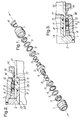
- Figure 1 the coupler is shown in exploded perspective view for purposes of illustration although it will be appreciated that after assembly of the coupler and ultrasonic welding of end pieces 1 to body member 2, non-destructive disassembly of the coupler is not possible.
- Figure 2 is a half axial section, partial view of the assembled coupler with a pipe 21 inserted in one end of the coupler. Since the coupler is symmetrical about a plane midway between its ends extending perpendicular to its longitudinal axis, substantially only the part of the coupling to one side of such plane is shown in Figures 2 and 3. This applies also to Figures 6 to 9.
- the coupler of Figure 3 is identical with that of Figure 2 except for the form of seal 4.
- the pipe 21 is a close sliding fit on the respective tubular portion 25.
- the grab-ring 3 is a split polymeric ring into which is moulded a plurality of metal teeth 11. As shown in Figures 2 and 3, the internal bore or passage through each end piece 1 includes an intermediate portion of uniform diameter which meets with a frusto-conical cam surface 12 which reduces in diameter towards the free end of the respective end piece. Each grab-ring 3 has, in an unstressed state, an outer diameter which is less than the diameter of said uniform-diameter intermediate portion of the bore through the end piece but is greater than the minimum internal diameter of the end piece 1, adjacent the free end of the latter, so that the grab-ring is held captive within the end piece 1.
- the grab-ring 3 has, extending towards its axial end nearer the open end of the end piece 1, an exterior cam surface tapering toward the axis of the fitting in the direction towards said open end of the end piece, for cooperation with the cam surface 12 and also has, extending towards the same axial end, an interior cam surface 17 flaring outwardly away from the axis of the fitting, in the direction toward said open end, for cooperation with a demounting tool 14.
- the grab-ring 3 causes the grab-ring 3 to activate such that the metal teeth 11 grip the pipe's outside diameter. Subsequent application of the system pressure causes the pipe and grab-ring 3 to move axially until the grab-ring 3 interacts with the cam surface 10. This causes the grab-ring 3 to contract radially inwardly thereby reinforcing the gripping mechanism which retains the pipe in the coupler.
- the grab ring 3 does not have an exterior cam surface as shown but is externally cylindrical over its whole axial extent, meeting the perpendicular outer end face of the grab ring in a square edge which cooperates with the cam surface 12. This arrangement allows the grab ring to activate and to become effective in a much shorter axial movement of the inserted pipe that with the arrangement illustrated in Figures 1 to 5B.
- the coupler is intended for use with composite pipe which is known to delaminate if the system fluid contact the pipe's end. This is prevented by sealing on the internal diameter of the pipe, by means of "O" rings 8, thereby isolating the pipe's end from the system fluid.
- the composite pipe is pushed firmly over the tubular portion 25 of the body member 2 until the pipe butts up against the end face 13 of the central part of body member 2, which end face 13 thus forms a pipe stop.
- the O-rings 8 are compressed between the body member 2 and pipe's internal diameter thereby producing an effective hydraulic seal.
- the seal 4 is compressed between the pipe's exterior and the internal surface of the end piece 2 thereby producing an effective hydraulic seal which is further improved by the application of system pressure.
- the spacer 6 ensures that the seal 4 is retained in the correct position such that the pipe can be fully inserted through the seal 4.
- the anti-extrusion ring 5 facilitates sealing and protects the seal 4 from damage.
- the coupler should be wholly compatible with both types of pipe.
- the O-rings 8 will not produce an effective seal with the equivalent copper pipe.
- the additional seal 4 which may be of any suitable type (“O" ring, as shown in Figure 2; "U” seal, as shown in Figure 3) is thus included to provide a means of sealing on the pipe's outside diameter.
- the gripping mechanism of the coupler as described above, requires no modification for use with copper pipe.
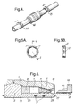
- the coupler can be demounted by means of a separate demounting tool 14 which comprises a longitudinally split annular member, (or alternatively a part-annular member) of the form illustrated in Figure 4 and including a collar portion from which extends a sleeve portion of small radial thickness and which conforms closely with the pipe surface when the demounting tool is applied to the pipe.
- the end of the sleeve portion remote from the collar portion is formed as a frusto-conically tapering cam surface complementary with the internal cam surface 17 at the outer end of the grab-ring 3.
- Ribs 15 extend longitudinally over the outer surface of the sleeve portion from the collar portion.
- the demounting tool 12 When it is necessary to release pipe 21 from the coupling, the demounting tool 12 is clipped over the pipe and the ribs 15 aligned with corresponding grooves 16 in the end piece 1.
- the demounting tool 14 is moved axially into the coupler until the grab-ring 3 is pushed back from the cam surface 10.
- the tapering cam surface of the demounting tool 14 interacts with the cam surface 17 of the grab-ring 3 so as to cause the grab-ring 3 to open up in the annular space 7. Retaining the demounting tool 14 and grab-ring 3 in this position removes the gripping force on the pipe 21 thereby allowing the pipe to be withdrawn.
- the coupler design is therefore inherently tamperproof as release of the pipe is not possible without the use of the demounting tool 14.
- the coupler is manufactured using standard injection moulding techniques from any polymeric material possessing suitable processing and in-service characteristics. Production of the coupler as a single moulding would be difficult due to the reverse draft angle of the cam surfaces 12.
- the coupler is therefore manufactured as a number of simplified components which are subsequently welded together by standard ultrasonic means.
- the internal components of the coupler (the grab-ring 3, seal 4, anti-extrusion ring 5 and spacer 6) are inserted in the end pieces 1 prior to fitting the end pieces 1 onto body member 2 and the subsequent ultrasonic welding process.
- the demountable coupler shown in partial half-axial section in Figure 6 is intended for use with composite pipe of the type referred to above comprising a metallic tube coated internally and externally with plastics.
- the pipe coupler shown in Figure 6 differs from that of Figures 1 to 4 principally in the form of the grab-ring 3, which in this instance is formed entirely of polymeric material.
- the grab-ring 3 is again axially split and has integral tooth formations in the form of angled surfaces extending radially inwardly from the body of the grab-ring. Furthermore, in this case the entire outer peripheral surface of the grab-ring is formed as a frusto-conical tapering surface complementary with the cam surface 12 of the respective end piece 1.
- the grab-ring 3 again provides internally, adjacent the open end of the fitting, a frusto-conically flaring surface 17 engagable by the complementary frusto-conical surface at the end of the demounting tool 14.
- the seal 4 and anti-extrusion ring 5 may in this case be dispensed with and may be replaced by a further spacer (not shown) accommodated in space 7 between spacer 4 and the grab-ring 3. Alternatively, the spacer 4 may be extended axially as compared with the spacer 4 in Figures 1 to 4.
- the pipe coupler shown in Figure 7 is again intended for use with composite pipe of the type comprising a metallic tube coated both internally and externally with a polymeric material, and differs from that of Figures 2 to 4 only in respect of the form of the grab-ring 3 and the omission of the "O" ring 4 - and anti-extrusion ring, etc.
- the coupler shown in Figure 8 is intended for use with "standard" copper and polymeric pipe.
- the coupler shown in Figure 8 differs from that of Figures 1 to 7 in lacking the inner tubular portions 25 of the body member 2 and consequently lacking the "O" rings 8.
- the "O" ring 4, anti-extrusion ring and grab-ring 3 are however retained.
- a grab-ring is again used possessing a plurality of metal teeth 11 moulded onto the back of a polymeric split-ring as shown in Figure 8, the form of the grab-ring being otherwise as described with reference to Figure 6.
- the coupler is intended for use with both copper and polymeric pipe.
- the pipe Upon insertion, the pipe is pushed firmly into the coupler through the grab-ring 3, seal 4, anti-extrusion ring 5, and spacer 6 until it butts up against the pipe stop 13.
- the seal 4 is compressed between the pipe's outside diameter and the peripheral wall of the annular space 7 thereby producing an effective hydraulic seal which is further improved by the application of system pressure.
- the spacer 6 ensures that the seal 4 is retained in the correct position such that the pipe can be fully inserted through the seal 4.
- the anti-extrusion ring 5 facilitates sealing and protects the seal 4 from damage.
- the demountable coupler illustrated in Figure 9 is again intended for use of "standard” copper and polymeric pipe.
- the coupler of Figure 9 differs from that of Figures 1 to 4 principally in that the uniform diameter tubular portions 25 of the body member 2 are eliminated and in that the internal diameter of the remaining portion of the body member 2 corresponds with that of the pipe 21.
- sealing is effected by the "O" ring 4 located between the interior of end part 1 and the exterior of pipe 25.
- the grab-ring 3 in Figure 9 again is a split polymeric carrier into which is moulded a plurality of metal teeth 11.
- the grab-ring in Figure 9 is similar in form to that in Figures 1 to 4. Insertion of the pipe causes the grab-ring 3 to activate such that the metal teeth 11 grip the pipe's outside diameter.
- Application of the system pressure causes the pipe and grab-ring 3 to move axially until the grab-ring 3 interacts with the cam surface 12. This causes the grab-ring 3 to close down thereby reinforcing the gripping mechanism which retains the pipe in the coupler.
- the coupler is intended for use with both copper and polymeric pipe.
- the pipe Upon insertion, the pipe is pushed firmly into the coupler through the grab-ring 3, seal 4, anti-extrusion ring 5, and spacer 6 until it butts up against the pipe stop 13.
- the seal 4 is compressed between the pipe's outside diameter and the peripheral wall of the annular space 7 thereby producing an effective hydraulic seal which is further improved by the application of system pressure.
- the spacer 6 ensures that the seal 4 is retained in the correct position such that the pipe can be fully inserted through the seal 4.
- the anti-extrusion ring 5 again facilitates sealing and protects the seal 4 from damage.
Abstract
In pipe couplings of the kind providing, within a socket (1, 2) to receive a pipe end (21), a grab ring (3) for engagement with the inserted pipe end (21), the grab ring (3) cooperating with an internally tapering or undercut portion of the socket, the internally tapering socket part (1) is formed separately from an annular central body part (2) which is welded to the tapering part (1) after assembly of the grab ring (3) and associated seals (4), if any, therein. The central body part (2) may carry an inner tubular portion (25) adapted to fit within the inserted pipe end and accommodating sealing rings (8) in peripheral grooves for sealing engagement with the interior surface of the inserted pipe end (21).
Description
- THIS INVENTION relates to pipe couplings of the type which can be fixed to pipes simply by insertion of the pipes into the couplings without the need for screw threaded unions or the like.
- British Patent No. 2166508 in the name of Glynwed Tubes and Fittings Limited discloses a pipe coupling providing a socket to receive a pipe end and, within the socket, a flexible seal received within a circumferential internal groove in the socket to make sealing engagement with the exterior of the pipe and, spaced axially from the seal and adjacent the free end of the socket, an internally toothed, axially split "grab-ring" received within a peripheral recess in the interior of the socket, the "grab-ring", in its unstressed state, having an internal diameter less than the external diameter of the pipe, the recess and the grab-ring having cooperating frusto-conically tapering cam faces such that axial movement of the grab-ring towards the free end of the socket produces circumferential contraction of the grab-ring about the pipe to permit such contraction.
- The coupling of British Patent No. 2166508 is intended primarily for use with plastics pipe of defined external diameter.
- It is an object of the present invention to provide a pipe coupler or joint which offers the advantages of the coupling of British Patent No. 2166508 but which is adaptable to different types of pipe.
- According to one aspect of the invention, there is provided a pipe coupling comprising a female pipe part for receiving an inserted male pipe part and also comprising a male tubular part for engagement within such inserted male pipe part, the coupling further including a so-called "grab" ring located in an undercut portion of the interior of the female pipe part, so as to be disposed on the exterior of such inserted male pipe part, the "grab" ring having a tapered external surface which engages a surface or edge in the undercut portion of the interior of the female pipe part, or the female pipe part having, in said undercut portion of its interior, a tapered internal surface which engages a surface or edge of said grab ring, sealing means being provided around said male tubular part whereby when such male pipe part is inserted within said female pipe part and over said male tubular part, the inserted pipe will be sealed with respect to the coupling by cooperation of said sealing means between the interior of the inserted male pipe part and the male tubular part, whilst the inserted male pipe part will be inserted through the grab-ring, which will engage the periphery of the inserted male pipe part and whereby, when the male pipe part is urged out of the female pipe part, either by fluid pressure or some other action, the grab-ring will be caused to ride along said tapered surface in the undercut portion of the female pipe part or the tapered surface of the grab ring (where provided) will be caused to ride along said edge or surface of the female pipe part, the grab ring, in either case, being thus caused to grip more firmly the inserted male pipe part.
- According to another aspect of the invention, there is provided a pipe coupling comprising a female pipe part for receiving a male pipe part and also comprising a resilient "grab" ring located with the female pipe part, the interior of the female pipe part being undercut to hold said grab ring captive, and wherein said female pipe part includes an annular central body part of substantial radial thickness and an end piece secured to said central body part, said end piece providing first and second opposite open ends, the first open end forming the open end of the pipe coupling for receiving such male pipe part and said second open end being of substantially greater internal diameter than said first end and of a size to receive at least a portion of said central body part, whereby, in assembly of the coupling, the grab-ring can be inserted into the interior of said end piece from said second end, said central body part subsequently inserted in said second end and said end piece subsequently welded to said central body part.
- Embodiments of the invention are described below by way of example with reference to the accompanying drawings, in which:
- FIGURE 1 is an exploded perspective view of a pipe coupling embodying the invention,
- FIGURE 2 is a partial, half-axial section of the pipe coupling of Figure 1,
- FIGURE 3 is a partial, half-axial section of a pipe coupling differing from that of Figure 2 only in the form of the outer sealing member,
- FIGURE 4 is a perspective view of a pipe joint incorporating the coupling of Figures 1 to 3 and illustrating use of a de-mounting tool to dis-assemble the joint,
- FIGURE 5A is an end elevation view of a grab-ring forming part of the coupler of Figures 1 to 4,
- FIGURE 5B is a view in section along the line A-A of Figure 5A - and - FIGURES 6, 7, 8 and 9 are respective, similar, partial, half-axial views of respective embodiments of pipe joints in accordance with the invention.
- In the drawings, and in the following description, like reference numerals denote like parts.
- The demountable coupler illustrated in Figures 1 to 5B is intended for use with "standard" copper or with composite pipe of the type comprising a metallic tube coated internally and externally with plastics.
- The coupler shown in Figures 1 to 5B, consists of two hollow tubular
plastics end pieces 1 ultrasonically welded to aplastics body member 2 having abore 23 therethrough. Thebody member 2 as initially formed has a central region of relatively large outer diameter from either end of which extends a respective integraltubular portion 25 of relatively small outer diameter, which outer diameter is substantially constant apart from two circumferential grooves in its outer peripheral surface to receive "O"rings 8. Eachend piece 1 as originally formed has a cylindrical recess extending into its inner end and which receives as an interference fit a respective end part of the central region of thebody member 2. Theend pieces 1, thus fitted onto the respective end parts of the central region of the body member are ultrasonically welded to the central region of the body member after assembly of the coupling with the other components referred to below. It will be understood that there is thus defined between eachend piece 2 and the respective smaller outer diameter tubular portion, a respectiveannular space 7. Whilst, in the drawings, the boundary between the central region of thebody member 2 and therespective end piece 1 is shown as being inclined with respect to the longitudinal axis of the fitting, implying a frusto-conical form for the respective surfaces, it is preferred that, as noted above, the respective surfaces are cylindrical prior to ultrasonic welding. A similar effect could be provided by retaining a frusto-conically external surface on the grab ring and forming the interior of theend piece 1 to provide an annular edge (which may be a square edge) cooperating with the frusto-conical surface of the grab ring. A respective grab-ring 3,seal 4,anti-extrusion ring 5 andspacer 6 sit in each of theannular spaces 7. Theseal 4 can be of any suitable type, for example an "O" ring as shown in Figure 2, or a "U" section seal as shown in Figure 3. In Figure 1, the coupler is shown in exploded perspective view for purposes of illustration although it will be appreciated that after assembly of the coupler and ultrasonic welding ofend pieces 1 tobody member 2, non-destructive disassembly of the coupler is not possible. Figure 2 is a half axial section, partial view of the assembled coupler with apipe 21 inserted in one end of the coupler. Since the coupler is symmetrical about a plane midway between its ends extending perpendicular to its longitudinal axis, substantially only the part of the coupling to one side of such plane is shown in Figures 2 and 3. This applies also to Figures 6 to 9. The coupler of Figure 3 is identical with that of Figure 2 except for the form ofseal 4. Thepipe 21 is a close sliding fit on the respectivetubular portion 25. - The grab-
ring 3 is a split polymeric ring into which is moulded a plurality ofmetal teeth 11. As shown in Figures 2 and 3, the internal bore or passage through eachend piece 1 includes an intermediate portion of uniform diameter which meets with a frusto-conical cam surface 12 which reduces in diameter towards the free end of the respective end piece. Each grab-ring 3 has, in an unstressed state, an outer diameter which is less than the diameter of said uniform-diameter intermediate portion of the bore through the end piece but is greater than the minimum internal diameter of theend piece 1, adjacent the free end of the latter, so that the grab-ring is held captive within theend piece 1. - The grab-
ring 3 has, extending towards its axial end nearer the open end of theend piece 1, an exterior cam surface tapering toward the axis of the fitting in the direction towards said open end of the end piece, for cooperation with thecam surface 12 and also has, extending towards the same axial end, aninterior cam surface 17 flaring outwardly away from the axis of the fitting, in the direction toward said open end, for cooperation with ademounting tool 14. When thepipe 21 is inserted (from the right in Figures 2 and 3) into theannular space 7, the pipe end, by engagement with the frusto-conicallyinclined surface 17 ofring 3 and subsequent engagement with theteeth 11, urges thering 3 inwardly away from the free end of the coupling until axial movement ofring 3 is restrained by engagement ofring 3 withanti-extrusion ring 5, in turn engagingsealing ring 4, in turnengaging spacer 6. Further insertion of the pipe end forces thering 3 to spring radially outwardly, i.e. to expand, allowing the pipe to pass through thering 3 until the pipe end engages theend face 13 of the central region ofbody member 2. Thus, insertion of thepipe 21 causes the grab-ring 3 to activate such that themetal teeth 11 grip the pipe's outside diameter. Subsequent application of the system pressure causes the pipe and grab-ring 3 to move axially until the grab-ring 3 interacts with the cam surface 10. This causes the grab-ring 3 to contract radially inwardly thereby reinforcing the gripping mechanism which retains the pipe in the coupler. In a variant, and currently preferred construction, not shown, thegrab ring 3 does not have an exterior cam surface as shown but is externally cylindrical over its whole axial extent, meeting the perpendicular outer end face of the grab ring in a square edge which cooperates with thecam surface 12. This arrangement allows the grab ring to activate and to become effective in a much shorter axial movement of the inserted pipe that with the arrangement illustrated in Figures 1 to 5B. - The coupler is intended for use with composite pipe which is known to delaminate if the system fluid contact the pipe's end. This is prevented by sealing on the internal diameter of the pipe, by means of "O"
rings 8, thereby isolating the pipe's end from the system fluid. Upon insertion, the composite pipe is pushed firmly over thetubular portion 25 of thebody member 2 until the pipe butts up against theend face 13 of the central part ofbody member 2, which endface 13 thus forms a pipe stop. The O-rings 8 are compressed between thebody member 2 and pipe's internal diameter thereby producing an effective hydraulic seal. - The
seal 4 is compressed between the pipe's exterior and the internal surface of theend piece 2 thereby producing an effective hydraulic seal which is further improved by the application of system pressure. Thespacer 6 ensures that theseal 4 is retained in the correct position such that the pipe can be fully inserted through theseal 4. Theanti-extrusion ring 5 facilitates sealing and protects theseal 4 from damage. - In some instances it may be necessary to use both copper and composite pipe in the same system. It is therefore preferred that the coupler should be wholly compatible with both types of pipe. As the internal diameter of a copper pipe will generally be greater than that of an equivalent composite pipe, (since it is the external diameter which is standardised), the O-
rings 8 will not produce an effective seal with the equivalent copper pipe. Theadditional seal 4, which may be of any suitable type ("O" ring, as shown in Figure 2; "U" seal, as shown in Figure 3) is thus included to provide a means of sealing on the pipe's outside diameter. The gripping mechanism of the coupler, as described above, requires no modification for use with copper pipe. - The coupler can be demounted by means of a
separate demounting tool 14 which comprises a longitudinally split annular member, (or alternatively a part-annular member) of the form illustrated in Figure 4 and including a collar portion from which extends a sleeve portion of small radial thickness and which conforms closely with the pipe surface when the demounting tool is applied to the pipe. The end of the sleeve portion remote from the collar portion is formed as a frusto-conically tapering cam surface complementary with theinternal cam surface 17 at the outer end of the grab-ring 3.Ribs 15 extend longitudinally over the outer surface of the sleeve portion from the collar portion. When it is necessary to releasepipe 21 from the coupling, thedemounting tool 12 is clipped over the pipe and theribs 15 aligned withcorresponding grooves 16 in theend piece 1. The demountingtool 14 is moved axially into the coupler until the grab-ring 3 is pushed back from the cam surface 10. The tapering cam surface of the demountingtool 14 interacts with thecam surface 17 of the grab-ring 3 so as to cause the grab-ring 3 to open up in theannular space 7. Retaining thedemounting tool 14 and grab-ring 3 in this position removes the gripping force on thepipe 21 thereby allowing the pipe to be withdrawn. The coupler design is therefore inherently tamperproof as release of the pipe is not possible without the use of thedemounting tool 14. - The coupler is manufactured using standard injection moulding techniques from any polymeric material possessing suitable processing and in-service characteristics. Production of the coupler as a single moulding would be difficult due to the reverse draft angle of the
cam surfaces 12. The coupler is therefore manufactured as a number of simplified components which are subsequently welded together by standard ultrasonic means. The internal components of the coupler (the grab-ring 3,seal 4,anti-extrusion ring 5 and spacer 6) are inserted in theend pieces 1 prior to fitting theend pieces 1 ontobody member 2 and the subsequent ultrasonic welding process. - The demountable coupler shown in partial half-axial section in Figure 6 is intended for use with composite pipe of the type referred to above comprising a metallic tube coated internally and externally with plastics.
- The pipe coupler shown in Figure 6 differs from that of Figures 1 to 4 principally in the form of the grab-
ring 3, which in this instance is formed entirely of polymeric material. - The grab-
ring 3 is again axially split and has integral tooth formations in the form of angled surfaces extending radially inwardly from the body of the grab-ring. Furthermore, in this case the entire outer peripheral surface of the grab-ring is formed as a frusto-conical tapering surface complementary with thecam surface 12 of therespective end piece 1. The grab-ring 3 again provides internally, adjacent the open end of the fitting, a frusto-conically flaring surface 17 engagable by the complementary frusto-conical surface at the end of thedemounting tool 14. Theseal 4 andanti-extrusion ring 5 may in this case be dispensed with and may be replaced by a further spacer (not shown) accommodated inspace 7 betweenspacer 4 and the grab-ring 3. Alternatively, thespacer 4 may be extended axially as compared with thespacer 4 in Figures 1 to 4. - Operation of the coupler, and de-mounting, are substantially as described with reference to Figures 1 to 4.
- The pipe coupler shown in Figure 7 is again intended for use with composite pipe of the type comprising a metallic tube coated both internally and externally with a polymeric material, and differs from that of Figures 2 to 4 only in respect of the form of the grab-
ring 3 and the omission of the "O" ring 4 - and anti-extrusion ring, etc. - The coupler shown in Figure 8 is intended for use with "standard" copper and polymeric pipe. The coupler shown in Figure 8 differs from that of Figures 1 to 7 in lacking the inner
tubular portions 25 of thebody member 2 and consequently lacking the "O" rings 8. The "O"ring 4, anti-extrusion ring and grab-ring 3 are however retained. In the case of copper pipe a purely polymeric grab-ring is unsuitable. Accordingly, a grab-ring is again used possessing a plurality ofmetal teeth 11 moulded onto the back of a polymeric split-ring as shown in Figure 8, the form of the grab-ring being otherwise as described with reference to Figure 6. - The coupler is intended for use with both copper and polymeric pipe. Upon insertion, the pipe is pushed firmly into the coupler through the grab-
ring 3,seal 4,anti-extrusion ring 5, andspacer 6 until it butts up against thepipe stop 13. Theseal 4 is compressed between the pipe's outside diameter and the peripheral wall of theannular space 7 thereby producing an effective hydraulic seal which is further improved by the application of system pressure. Thespacer 6 ensures that theseal 4 is retained in the correct position such that the pipe can be fully inserted through theseal 4. Theanti-extrusion ring 5 facilitates sealing and protects theseal 4 from damage. - The demountable coupler illustrated in Figure 9 is again intended for use of "standard" copper and polymeric pipe.
- The coupler of Figure 9 differs from that of Figures 1 to 4 principally in that the uniform diameter
tubular portions 25 of thebody member 2 are eliminated and in that the internal diameter of the remaining portion of thebody member 2 corresponds with that of thepipe 21. Thus, in this case, sealing is effected by the "O"ring 4 located between the interior ofend part 1 and the exterior ofpipe 25. - The grab-
ring 3 in Figure 9 again is a split polymeric carrier into which is moulded a plurality ofmetal teeth 11. The grab-ring in Figure 9 is similar in form to that in Figures 1 to 4. Insertion of the pipe causes the grab-ring 3 to activate such that themetal teeth 11 grip the pipe's outside diameter. Application of the system pressure causes the pipe and grab-ring 3 to move axially until the grab-ring 3 interacts with thecam surface 12. This causes the grab-ring 3 to close down thereby reinforcing the gripping mechanism which retains the pipe in the coupler. - The coupler is intended for use with both copper and polymeric pipe. Upon insertion, the pipe is pushed firmly into the coupler through the grab-
ring 3,seal 4,anti-extrusion ring 5, andspacer 6 until it butts up against thepipe stop 13. Theseal 4 is compressed between the pipe's outside diameter and the peripheral wall of theannular space 7 thereby producing an effective hydraulic seal which is further improved by the application of system pressure. Thespacer 6 ensures that theseal 4 is retained in the correct position such that the pipe can be fully inserted through theseal 4. Theanti-extrusion ring 5 again facilitates sealing and protects theseal 4 from damage. - It will be appreciated that in some cases it may be desired to connect two different types of pipe end to end and that for such cases there may be provided for example, a pipe coupling one half of which has, in axial section, the form shown in Figure 2 and the other half of which has, in axial section, the form shown in Figure 8. Similarly, pipe couplings may be provided which similarly combine any two of the forms illustrated in Figures 2, 6, 7, 8 or 9.
- The features disclosed in the foregoing description, in the following claims and/or in the accompanying drawings may, both separately and in any combination thereof, be material for realising the invention in diverse forms thereof.
Claims (7)
- A pipe coupling comprising a female pipe part for receiving an inserted male pipe part and also comprising a male tubular part for engagement within such inserted male pipe part, the coupling further including a so-called "grab" ring located in an undercut portion of the interior of the female pipe part, so as to be disposed on the exterior of such inserted male pipe part, the "grab" ring having a tapered external surface which engages a surface or edge in the undercut portion of the interior of the female pipe part, or the female pipe part having, in said undercut portion of its interior, a tapered internal surface which engages a surface or edge of said grab ring, sealing means being provided around said male tubular part whereby when such male pipe part is inserted within said female pipe part and over said male tubular part, the inserted pipe will be sealed with respect to the coupling by cooperation of said sealing means between the interior of the inserted male pipe part and the male tubular part, whilst the inserted male pipe part will be inserted through the grab-ring, which will engage the periphery of the inserted male pipe part and whereby, when the male pipe part is urged out of the female pipe part, either by fluid pressure or some other action, the grab-ring will be caused to ride along said tapered surface in the undercut portion of the female pipe part or the tapered surface of the grab ring (where provided) will be caused to ride along said edge or surface of the female pipe part, the grab ring, in either case, being thus caused to grip more firmly the inserted male pipe part.
- A pipe joint comprising the pipe coupling of Figure 1 with an inserted male pipe part fitting closely over said male tubular portion and received as an interference fit within said grab-ring.
- The pipe coupling of claim 1, further including a sealing member disposed, within said female pipe part, further than said grab-ring from the open end of the female pipe part than said grab ring, said sealing member cooperating sealingly with the internal surface of said female pipe part and being spaced radially from said male tubular portion to allow space for passage of a said inserted male pipe part.
- A pipe coupling comprising a female pipe part for receiving a male pipe part and also comprising a resilient "grab" ring located with the female pipe part, the interior of the female pipe part being undercut to hold said grab ring captive, and wherein said female pipe part includes an annular central body part of substantial radial thickness and an end piece secured to said central body part, said end piece providing first and second opposite open ends, the first open end forming the open end of the pipe coupling for receiving such male pipe part and said second open end being of substantially greater internal diameter than said first end and of a size to receive at least a portion of said central body part, whereby, in assembly of the coupling, the grab-ring can be inserted into the interior of said end piece from said second end, said central body part subsequently inserted in said second end and said end piece subsequently welded to said central body part.
- A method of manufacturing a pipe coupling comprising a female pipe part for receiving a male pipe part and also comprising a resilient "grab" ring located with the female pipe part, the interior of the female pipe part being undercut to hold said grab ring captive, and wherein said female pipe part includes an annular central body part of substantial radial thickness and an end piece secured to said central body part, said end piece providing first and second opposite open ends, the first open end forming the open end of the pipe coupling for receiving such male pipe part and said second open end being of substantially greater internal diameter than said first end and of a size to receive at least a portion of said central body part, whereby, in assembly of the coupling, the grab-ring can be inserted into the interior of said end piece from said second end, said central body part subsequently inserted in said second end and said end piece subsequently welded to said central body part.
- A pipe joint incorporating a pipe coupling according to claim 4 or made by the method of claim 5.
- A grab-ring for a pipe-coupling, comprising a split annular polymeric body having at least one tooth of harder material than said body moulded into said body and projecting therefrom on the interior of the ring.
Applications Claiming Priority (2)
| Application Number | Priority Date | Filing Date | Title |
|---|---|---|---|
| GB9506183 | 1995-03-27 | ||
| GBGB9506183.4A GB9506183D0 (en) | 1995-03-27 | 1995-03-27 | Improvements in or relating to pipe couplings |
Publications (2)
| Publication Number | Publication Date |
|---|---|
| EP0735306A2 true EP0735306A2 (en) | 1996-10-02 |
| EP0735306A3 EP0735306A3 (en) | 1996-11-13 |
Family
ID=10771942
Family Applications (1)
| Application Number | Title | Priority Date | Filing Date |
|---|---|---|---|
| EP96103064A Withdrawn EP0735306A3 (en) | 1995-03-27 | 1996-02-29 | Pipe couplings |
Country Status (2)
| Country | Link |
|---|---|
| EP (1) | EP0735306A3 (en) |
| GB (1) | GB9506183D0 (en) |
Cited By (17)
| Publication number | Priority date | Publication date | Assignee | Title |
|---|---|---|---|---|
| GB2325718A (en) * | 1997-05-27 | 1998-12-02 | Hepworth Building Prod | Grab ring and socket incorporating a grab ring |
| GB2317212B (en) * | 1995-07-07 | 1999-10-13 | Marley Extrusions | Push-fit tube couplings |
| GB2348686A (en) * | 1999-03-31 | 2000-10-11 | Marley Extrusions | Pipe coupling with grip rings |
| WO2001071235A1 (en) * | 2000-03-23 | 2001-09-27 | Legris Sa | Sliding device connecting the end of a tube to an end piece |
| WO2002029301A1 (en) * | 2000-10-04 | 2002-04-11 | Bsw Limited | A device for gripping a pipe or bar |
| FR2824618A1 (en) * | 2001-05-14 | 2002-11-15 | Comap | Instant coupling e.g. for plastic-coated aluminum pipes has tubular insert with annular groove for seal and outer fastening ring |
| EP0838006B1 (en) * | 1995-07-07 | 2004-09-29 | Marley Extrusions Limited | Push-fit tube couplings |
| GB2420603A (en) * | 2004-11-29 | 2006-05-31 | Glynwed Pipe Systems Ltd | Pipe fittings |
| EP1669656A1 (en) * | 2004-12-07 | 2006-06-14 | IPA Produktions- & Vertriebsges.m.b.H. | Connecting device for pipes |
| EP1972845A1 (en) * | 2007-03-22 | 2008-09-24 | Geberit Technik Ag | Fitting for water pipes |
| WO2014072539A1 (en) * | 2012-11-07 | 2014-05-15 | Hita Technology Of Plastic System S.L. | Rapid-action coupling for pipes |
| WO2016172408A1 (en) * | 2015-04-23 | 2016-10-27 | Swagelock Company | Single action push to connect conduit fitting with colleting |
| US9903518B2 (en) | 2013-10-24 | 2018-02-27 | Swagelok Company | Single action push to connect conduit fitting |
| US9958100B2 (en) | 2010-10-15 | 2018-05-01 | Swagelok Company | Push to connect conduit fitting with ferrule |
| US10458582B2 (en) | 2015-04-23 | 2019-10-29 | Swagelok Company | Single action push to connect conduit fitting with colleting |
| WO2023020116A1 (en) * | 2021-08-18 | 2023-02-23 | 日丰企业(佛山)有限公司 | Pipeline supply system and pipeline connection structure thereof |
| US11781688B2 (en) | 2019-04-01 | 2023-10-10 | Swagelok Company | Push to connect conduit fitting assemblies and arrangements |
Citations (4)
| Publication number | Priority date | Publication date | Assignee | Title |
|---|---|---|---|---|
| US4282175A (en) * | 1978-04-25 | 1981-08-04 | Perfection Corporation | Stab-type coupling and method |
| EP0310234A2 (en) * | 1987-09-29 | 1989-04-05 | Bridgestone Flowtech Corporation | Hose fitting |
| EP0460791A1 (en) * | 1990-06-07 | 1991-12-11 | Nitta Moore Company | Pipe joint with pipe slipout prevention means |
| US5366260A (en) * | 1993-04-14 | 1994-11-22 | Continental Industries, Inc. | Plastic pipe coupler |
-
1995
- 1995-03-27 GB GBGB9506183.4A patent/GB9506183D0/en active Pending
-
1996
- 1996-02-29 EP EP96103064A patent/EP0735306A3/en not_active Withdrawn
Patent Citations (4)
| Publication number | Priority date | Publication date | Assignee | Title |
|---|---|---|---|---|
| US4282175A (en) * | 1978-04-25 | 1981-08-04 | Perfection Corporation | Stab-type coupling and method |
| EP0310234A2 (en) * | 1987-09-29 | 1989-04-05 | Bridgestone Flowtech Corporation | Hose fitting |
| EP0460791A1 (en) * | 1990-06-07 | 1991-12-11 | Nitta Moore Company | Pipe joint with pipe slipout prevention means |
| US5366260A (en) * | 1993-04-14 | 1994-11-22 | Continental Industries, Inc. | Plastic pipe coupler |
Cited By (33)
| Publication number | Priority date | Publication date | Assignee | Title |
|---|---|---|---|---|
| GB2317212B (en) * | 1995-07-07 | 1999-10-13 | Marley Extrusions | Push-fit tube couplings |
| EP0838006B1 (en) * | 1995-07-07 | 2004-09-29 | Marley Extrusions Limited | Push-fit tube couplings |
| GB2325718B (en) * | 1997-05-27 | 2002-07-31 | Hepworth Building Prod | Grab ring and socket incorporating a grab ring |
| GB2325718A (en) * | 1997-05-27 | 1998-12-02 | Hepworth Building Prod | Grab ring and socket incorporating a grab ring |
| GB2348686B (en) * | 1999-03-31 | 2003-07-23 | Marley Extrusions | Pipe couplings with grip rings |
| GB2348686A (en) * | 1999-03-31 | 2000-10-11 | Marley Extrusions | Pipe coupling with grip rings |
| FR2806780A1 (en) * | 2000-03-23 | 2001-09-28 | Legris Sa | SLIDING DEVICE FOR CONNECTING THE END OF A TUBE TO A TIP |
| WO2001071235A1 (en) * | 2000-03-23 | 2001-09-27 | Legris Sa | Sliding device connecting the end of a tube to an end piece |
| WO2002029301A1 (en) * | 2000-10-04 | 2002-04-11 | Bsw Limited | A device for gripping a pipe or bar |
| AU2001293966B2 (en) * | 2000-10-04 | 2006-08-31 | Bsw Limited | A device for gripping a pipe or bar |
| US6991265B2 (en) | 2000-10-04 | 2006-01-31 | Bsw Limited | Device for gripping a pipe or bar |
| FR2824618A1 (en) * | 2001-05-14 | 2002-11-15 | Comap | Instant coupling e.g. for plastic-coated aluminum pipes has tubular insert with annular groove for seal and outer fastening ring |
| EP1258666A1 (en) * | 2001-05-14 | 2002-11-20 | Comap | Quick connector with fastening by elastic external ring |
| GB2420603B (en) * | 2004-11-29 | 2009-11-04 | Glynwed Pipe Systems Ltd | Pipe fittings |
| GB2420603A (en) * | 2004-11-29 | 2006-05-31 | Glynwed Pipe Systems Ltd | Pipe fittings |
| EP1669656A1 (en) * | 2004-12-07 | 2006-06-14 | IPA Produktions- & Vertriebsges.m.b.H. | Connecting device for pipes |
| EP1972845A1 (en) * | 2007-03-22 | 2008-09-24 | Geberit Technik Ag | Fitting for water pipes |
| US9958100B2 (en) | 2010-10-15 | 2018-05-01 | Swagelok Company | Push to connect conduit fitting with ferrule |
| US11002395B2 (en) | 2010-10-15 | 2021-05-11 | Swagelok Company | Push to connect conduit fitting with ferrule |
| US10584820B2 (en) | 2010-10-15 | 2020-03-10 | Swagelok Company | Push to connect conduit fitting with ferrule |
| WO2014072539A1 (en) * | 2012-11-07 | 2014-05-15 | Hita Technology Of Plastic System S.L. | Rapid-action coupling for pipes |
| EP2949984A4 (en) * | 2012-11-07 | 2016-11-16 | Hita Technology Of Plastic System S L | Rapid-action coupling for pipes |
| US10619780B2 (en) | 2013-10-24 | 2020-04-14 | Swagelok Company | Single action push to connect conduit fitting |
| US9903518B2 (en) | 2013-10-24 | 2018-02-27 | Swagelok Company | Single action push to connect conduit fitting |
| US10458582B2 (en) | 2015-04-23 | 2019-10-29 | Swagelok Company | Single action push to connect conduit fitting with colleting |
| EP3597979A1 (en) | 2015-04-23 | 2020-01-22 | Swagelok Company | Single action push to connect conduit fitting with colleting |
| CN107532758A (en) * | 2015-04-23 | 2018-01-02 | 世伟洛克公司 | Individual part with set folder promotes the pipe joint of connection |
| US10704722B2 (en) | 2015-04-23 | 2020-07-07 | Swagellok Company | Single action push to connect conduit fitting |
| CN107532758B (en) * | 2015-04-23 | 2020-10-13 | 世伟洛克公司 | Single action push to connect pipe joint with collets |
| WO2016172408A1 (en) * | 2015-04-23 | 2016-10-27 | Swagelock Company | Single action push to connect conduit fitting with colleting |
| US11073234B2 (en) | 2015-04-23 | 2021-07-27 | Swagelok Company | Single action push to connect conduit fitting |
| US11781688B2 (en) | 2019-04-01 | 2023-10-10 | Swagelok Company | Push to connect conduit fitting assemblies and arrangements |
| WO2023020116A1 (en) * | 2021-08-18 | 2023-02-23 | 日丰企业(佛山)有限公司 | Pipeline supply system and pipeline connection structure thereof |
Also Published As
| Publication number | Publication date |
|---|---|
| EP0735306A3 (en) | 1996-11-13 |
| GB9506183D0 (en) | 1995-05-17 |
Similar Documents
| Publication | Publication Date | Title |
|---|---|---|
| EP0735306A2 (en) | Pipe couplings | |
| AU693025B2 (en) | Coupling assembly | |
| US5088771A (en) | Tube union | |
| AU625609B2 (en) | Quick connect fitting | |
| US4893848A (en) | Hose coupling | |
| US5425557A (en) | Apparatus for and method of attaching hoses and tubes to a fitting | |
| US6142538A (en) | Stab-type coupling with conduit inner diameter seal | |
| US4991882A (en) | Fluid-tight connector | |
| EP0480478B1 (en) | Tube coupling | |
| US4932689A (en) | Hose fitting assembly | |
| EP0897082B1 (en) | Push fit tube couplings | |
| US4556242A (en) | Vibration resistant high pressure tube fitting | |
| US4343498A (en) | Swivel hose coupling | |
| US4220359A (en) | Push-to-connect air brake fitting | |
| US3521912A (en) | Tube coupling having deformable gripping means | |
| EP0972981A2 (en) | Improvements in or relating to grab rings | |
| US7846365B2 (en) | Method of manufacture of a nut and tail assembly | |
| GB2146402A (en) | High pressure tube fitting | |
| US6832791B2 (en) | Connection means for interconnecting two duct elements | |
| RU2711704C2 (en) | Clamping fitting | |
| US5671955A (en) | Threadless pipe coupler for sprinkler pipe | |
| CA2080359A1 (en) | Apparatus for attaching a hose to a fitting | |
| US3338598A (en) | Coupling method and devices for lined pipe | |
| US4243254A (en) | Slip fit type tubing coupling | |
| US7488006B2 (en) | Coupling assembly |
Legal Events
| Date | Code | Title | Description |
|---|---|---|---|
| PUAI | Public reference made under article 153(3) epc to a published international application that has entered the european phase |
Free format text: ORIGINAL CODE: 0009012 |
|
| PUAL | Search report despatched |
Free format text: ORIGINAL CODE: 0009013 |
|
| AK | Designated contracting states |
Kind code of ref document: A2 Designated state(s): AT BE CH DE DK ES FR GB GR IE IT LI LU MC NL PT SE |
|
| AK | Designated contracting states |
Kind code of ref document: A3 Designated state(s): AT BE CH DE DK ES FR GB GR IE IT LI LU MC NL PT SE |
|
| STAA | Information on the status of an ep patent application or granted ep patent |
Free format text: STATUS: THE APPLICATION IS DEEMED TO BE WITHDRAWN |
|
| 18D | Application deemed to be withdrawn |
Effective date: 19970514 |