EP0735248A2 - Multiple valve internal combustion engine - Google Patents
Multiple valve internal combustion engine Download PDFInfo
- Publication number
- EP0735248A2 EP0735248A2 EP96105096A EP96105096A EP0735248A2 EP 0735248 A2 EP0735248 A2 EP 0735248A2 EP 96105096 A EP96105096 A EP 96105096A EP 96105096 A EP96105096 A EP 96105096A EP 0735248 A2 EP0735248 A2 EP 0735248A2
- Authority
- EP
- European Patent Office
- Prior art keywords
- valve
- valves
- cylinder head
- valve seats
- distance
- Prior art date
- Legal status (The legal status is an assumption and is not a legal conclusion. Google has not performed a legal analysis and makes no representation as to the accuracy of the status listed.)
- Granted
Links
Images


Classifications
-
- F—MECHANICAL ENGINEERING; LIGHTING; HEATING; WEAPONS; BLASTING
- F01—MACHINES OR ENGINES IN GENERAL; ENGINE PLANTS IN GENERAL; STEAM ENGINES
- F01L—CYCLICALLY OPERATING VALVES FOR MACHINES OR ENGINES
- F01L1/00—Valve-gear or valve arrangements, e.g. lift-valve gear
- F01L1/26—Valve-gear or valve arrangements, e.g. lift-valve gear characterised by the provision of two or more valves operated simultaneously by same transmitting-gear; peculiar to machines or engines with more than two lift-valves per cylinder
- F01L1/265—Valve-gear or valve arrangements, e.g. lift-valve gear characterised by the provision of two or more valves operated simultaneously by same transmitting-gear; peculiar to machines or engines with more than two lift-valves per cylinder peculiar to machines or engines with three or more intake valves per cylinder
-
- F—MECHANICAL ENGINEERING; LIGHTING; HEATING; WEAPONS; BLASTING
- F01—MACHINES OR ENGINES IN GENERAL; ENGINE PLANTS IN GENERAL; STEAM ENGINES
- F01L—CYCLICALLY OPERATING VALVES FOR MACHINES OR ENGINES
- F01L3/00—Lift-valve, i.e. cut-off apparatus with closure members having at least a component of their opening and closing motion perpendicular to the closing faces; Parts or accessories thereof
- F01L3/22—Valve-seats not provided for in preceding subgroups of this group; Fixing of valve-seats
-
- F—MECHANICAL ENGINEERING; LIGHTING; HEATING; WEAPONS; BLASTING
- F02—COMBUSTION ENGINES; HOT-GAS OR COMBUSTION-PRODUCT ENGINE PLANTS
- F02F—CYLINDERS, PISTONS OR CASINGS, FOR COMBUSTION ENGINES; ARRANGEMENTS OF SEALINGS IN COMBUSTION ENGINES
- F02F1/00—Cylinders; Cylinder heads
- F02F1/24—Cylinder heads
- F02F1/42—Shape or arrangement of intake or exhaust channels in cylinder heads
- F02F1/4214—Shape or arrangement of intake or exhaust channels in cylinder heads specially adapted for four or more valves per cylinder
-
- F—MECHANICAL ENGINEERING; LIGHTING; HEATING; WEAPONS; BLASTING
- F02—COMBUSTION ENGINES; HOT-GAS OR COMBUSTION-PRODUCT ENGINE PLANTS
- F02B—INTERNAL-COMBUSTION PISTON ENGINES; COMBUSTION ENGINES IN GENERAL
- F02B2275/00—Other engines, components or details, not provided for in other groups of this subclass
- F02B2275/18—DOHC [Double overhead camshaft]
-
- F—MECHANICAL ENGINEERING; LIGHTING; HEATING; WEAPONS; BLASTING
- F02—COMBUSTION ENGINES; HOT-GAS OR COMBUSTION-PRODUCT ENGINE PLANTS
- F02F—CYLINDERS, PISTONS OR CASINGS, FOR COMBUSTION ENGINES; ARRANGEMENTS OF SEALINGS IN COMBUSTION ENGINES
- F02F1/00—Cylinders; Cylinder heads
- F02F1/24—Cylinder heads
- F02F2001/244—Arrangement of valve stems in cylinder heads
- F02F2001/245—Arrangement of valve stems in cylinder heads the valve stems being orientated at an angle with the cylinder axis
Definitions
- This invention relates to a multiple valve internal combustion engine comprising a cylinder head unit having valve seats in associated valve openings operable by respective valves slidingly received in associated valve guides, said valve seats consisting of a metal different to the metal of a cylinder head, and a method for producing a valve seat within a cylinder head unit of a multiple valve internal combustion engine.
- valve seats are usually installed by press-fitting around the circumference of the air intake and exhaust port openings in the cylinder head.
- valve seats With pressed-in valve seats, however, the valve seats themselves must have enough strength and durability to withstand the pressing operation, and as a result, they are comparatively thick, and they are relatively deep to accommodate the press-fitting operation. In multivalve engines with a high number of valves, using these seats requires that there be some distance separating the valves, and this feature imposes limits on the valve diameter and how closely they may be positioned to the dome of the combustion chamber. These limitations in turn limit the degree to which the amount of air intake gas can be increased.
- this objective is solved in that said valve seats are metallurgically bonded to said cylinder head and that a first distance between adjacent valve seats is greater than or equal to a second distance between adjacent valves when said valves are in fully closed position and/or in that said valve seats are metallurgically bonded to said cylinder head and that a third distance between a bottom end of a contact surface of said valve seats with said valves and an edge of a casting skin of a combustion chamber is smaller than or equal to a fourth distance between the bottom surface of said valves and said bottom end of said contact surface, when said valves are in fully closed position, whereby said edge is produced by applying a finishing treatment to said valve seats.
- these valves are intake valves whereby it is advantageous for a more effective heat transfer that a water jacket positioned between said valves seat or valves, respectively, comprises a lower wall being arranged adjacent said valve seats.
- valve seats being much smaller than conventional valve seats, it is possible to increase the air intake gas flows for a multiple valve internal combustion engine having three air intake valves and two exhaust valves.
- a plastic deformation layer By forming of said plastic deformation layer, bonding strength between the valve seats and the cylinder head unit is surprisingly and unexpectedly increased, despite the fact that no permanent melting reaction layers are formed.
- the bonding results neither from the recess configuration nor the valve seats configuration, the area around the valve seats and the cylinder head unit can be reduced, thereby realizing a compact cylinder head unit.
- valve seats are typically made of an Fe-based sinted alloy, and the cylinder head unit is typically made of an aluminium alloy. Further, the valve seats preferably have metal deposits (such that made of Cu) capable of forming an eutectic alloy with a cylinder head unit so that the metal deposits and the material of said cylinder head unit undergo a so-called solid-state diffusion.
- the solid-state diffusion may take place between the material of the valve seats and the material of the cylinder head unit without said metal deposits.
- the metal deposits are present it is possible to obtain a high level bonding strength.
- this objective is solved for a method for producing a valve seat as indicated above by comprising the steps of: (a) placing a valve seat insert onto the surface of an opening within said cylinder head unit, (b) pressing said valve seat insert against said cylinder head unit and then impressing a voltage between the abutting surfaces of said valve seat insert and said cylinder head unit, so that said valve seat insert and said cylinder head unit are metallurgically bonded with each other, and (c) applying a finishing treatment to said bonded pieces so that said valve seats are metallurgically boned to said cylinder head and that a first distance between adjacent valve seats is greater than or equal to a second distance between adjacent insertable valves, and/or that a third distance between a bottom end of a contact surface of said valve seats with said insertable valves and an edge of a casting skin of a combustion chamber is smaller than or equal to a fourth distance between the bottom surface of said insertable valves and said bottom end of said contact surface when said insertable valves are in fully closed position,
- valve seat insert with metal deposits which are capable of forming an eutectic alloy with said cylinder head unit, whereby it is possible to provide said valve seat insert with a film coating of said metal deposits.
- coating it is advantageous to provide said coating with a thickness of 0.1-30 ⁇ m, for instance by electroplating, non-electrical plating or by injection molding.
- the diameter of the valves by using bonded valve seats which are laid out so that the distance between the valve seats is greater than or equal to the distance between the valves when they are fully closed, thereby making it possible to increase the gas exchange volume of said internal combustion engine, in turn allowing increased engine output due to the increased availability of air intake gas.
- valves it is possible to position the valves in closer proximity to the dome of the combustion chamber because of the use of bonded valve seats which are installed in a manner such that the distance between the bottom end of the contact surface of the valve seat to the edge of the combustion chamber casting skin is less than or equal to the distance from the bottom surface of the valve to the bottom end of the valve seat contact surface.
- This design especially reduces the air intake flow resistance to the intake flow passing the air intake valve. This feature allows an increase in the amount of air intake gas, in turn allowing improved engine output.
- the diameter of the air intake valves has been increased, or the valves have been located in closer proximity to the dome of the combustion chamber, whereby the amount of air intake is increased and engine output is improved.
- the heat conduction distance between the water jacket and the valve seat and valve has been shortened, and further, because the valve seat itself is very thin, this design allows better cooling of the valve and valve seat, thereby lowering their temperatures and increasing the strength of the valve and valve seat.
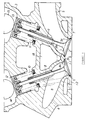
- Figure 1 is a vertical sectional view of the cylinder head of an internal combustion engine according to this invention
- Figure 2 is an enlarged sectional view of the area around the air intake port of the same cylinder head.
- the internal combustion engine in this embodiment is a four cycle, 5-valve engine comprising, for each cylinder, three air intake valves 1-1, 1-2 (1-1 represents the air intake valves on both sides and 1-2 is the center air intake valve (center valve)) and two exhaust valves 2 (see Figure 1).
- the air intake valves 1-1, 1-2 and exhaust valves 2 that are installed into the respective three air intake ports 4 and the two exhaust ports 5 that are formed in the lightweight Al alloy cylinder head 3 are opened and closed at the appropriate timing to perform the required gas exchange.
- concave combustion domes 3a which comprise the combustion chambers S.
- the above mentioned air intake valves 1-1, 1-2 and exhaust valves 2 are intermittently seated against the valve seats 6, 7 installed around the circumference of the openings of the foregoing air intake ports 4 and exhaust ports 5 in the combustion chamber.
- the air intake valves 1-1, 1-2 and the exhaust valves 2 are slidably inserted into respective valve guides 8, 9, and they are held in the normally closed position by the valve springs 10, 11.
- the air intake valves 1-1, 1-2 and the exhaust valves 2 are driven at the appropriate timing by rotating cams 14, 15 that are in sliding contact with the valve lifters 12, 13.
- valve seats 6, 7 are bonded valve seats that are formed from Fe type sintering material with excellent impact strength, wear resistance and high temperature strength, and their surface comprises a film coating 16 (see Figure 9) that is 0.1 to 30 ⁇ m thick. These seats are bonded to the cylinder head 3 by resistance heating. Also, the pores in the Fe sintered stock that comprises said bonded valve seats 6, 7 are filled by immersing them in a molten metal such as Cu, which offers high heat conductivity and self-lubricating properties.
- the material used for the foregoing film coating should be selected from materials that will form co-crystallization alloys with Al, the primary component of the Al alloy constituting the cylinder head, and which evince a melting point lower than that of Al or the principal alloy components.
- Cu was used for that purpose.
- the Cu film coating 16 was formed in the present embodiment by electroplating, but it is also possible to use a non-electrical plating method, or to injection-mold the film coating 16.
- the melting points of Al and Cu by themselves are 660°C and 1083°C, respectively, the melting point of Al-Cu alloy at the co-crystal point is 548°C, which is lower than the melting points of either Al or Cu (660°C, 1083°C). Accordingly, it is possible to form an Al-Cu co-crystal alloy with a melting point lower than Al or Cu.
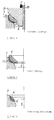
- Figures 3 through 8 are cutaway sectional views that will be used to explain the bonding process for the bonded valve seats;
- Figure 9 is a detailed enlargement of the A area in Figure 4, and
- Figure 10 is a detailed enlargement of the B area in Figure 5.
- the projection 6a on the outside circumference of the valve seat 6 is brought into contact with the projection 6 on the circumference of the air intake port 4 of the cylinder head 3.
- the upper electrode 21 shown in Figure 4 is guided by a guide bar 20 inserted into the valve guide hole that was previously formed in the cylinder head 3.
- the upper electrode 21 of the resistance welding machine which can slide up and down along the guide bar 20, is inserted into the inside tapered surface 6b of the bonded valve seat 6, in a manner such that the upper electrode 21 applies a certain force F to the bonded valve seat 6 and holds it against the cylinder head 3.
- the Al alloy of the cylinder head stock and the Cu constituting the film coating 16 are in solid phase contact, pressing against each other.
- the contact between the valve seat 6 and the cylinder head 3 is as shown in Figure 9.
- valve seat 6 causes the valve seat 6 to be strongly bonded to the cylinder head 3, at which time the current is cut off. Then, as shown in Figure 6, a plastic deformation layer 17 is formed at the contact interface between the valve seat 6 and the cylinder head 3, and the liquid phase extruded at the ends of the contact interface solidifies.
- valve seat 6 is machined and finished to the desired shape, which operation completes the bonding of the valve seat to the cylinder head, and which results in the valve seat 6 being strongly integrated into the cylinder head 3 around the opening of the air intake port 4.
- the bonded valve seats 6, 7 bonded in the above described manner are very thin (normally about 500 ⁇ m), and because their widths and heights are also very slight, as is shown in Figure 2 for example, the distance a 1 between the valve seats 6 on the air intake side can be selected to be greater than or equal to the distance b 1 between the air intake valves 1-1, 1-2 when they are in their fully closed position (a 1 ⁇ b 1 ).
- the distance a 1 between the valve seats 6 on the air intake side can be selected to be greater than or equal to the distance b 1 between the air intake valves 1-1, 1-2 when they are in their fully closed position (a 1 ⁇ b 1 ).
- This feature makes it possible to improve engine output by increasing the amount of air intake gas supplied to through the air intake valves 1-1, 1-2 into the inside of the cylinder (not shown).
- the a surface is the casting skin of the combustion chamber S.
- the distance c from the bottom end P of the contact surface of the valve seat 6 to the edge Q of the casting skin of the combustion chamber is selected to be less than the distance d from the bottom surface of the air intake valves 1-1, 1-2 to the bottom end of the contact surface P of the valve seat 6 (c ⁇ d).
- This edge Q is always formed by finishing the last surface of the bonded valve seat as well as of conventional valve seats. The finishing space should be small, because a reduction of the aluminium body between adjacent valve seats should be avoided for strength reasons.
- a water jacket 18 is formed in the cylinder head 3 for the purpose of circulating coolant, but since the bonded valve seats 6, 7 are employed in this embodiment, it is possible to form the lower wall 18a of the water jacket 18 in the throat area 4a, 5a of the air intake ports 4 and exhaust ports 5. This feature results in shortened heat conduction distance between the water jacket 18, and the valves seats 6, 7 as well as the air intake and exhaust valves 1-1, 1-2, 2.
- valve seats 6, 7 are themselves very thin, there is a further enhancement of the cooling available for the air intake and exhaust valves 1-1, 1-2, 2 and the valve seats 6, 7, lowering their temperature and resulting in higher actual strength for said air intake and exhaust valves 1-1, 1-2, 2 and valve seats 6, 7.
- bonded valve seats are used in this invention and the distance between valve seats is selected to be greater than or equal to the distance between the fully closed valves, thereby making it possible to increase the valve diameter, thus improving gas exchange volume in the internal combustion engine.
- This feature makes it possible to increase the amount of intake gas and improve engine output.
- bonded valve seats are used and the distance from the bottom of the contact surface of the valve seats to the edge of the casting skin of the combustion chamber is selected to be less than or equal to the distance from the bottom surface of the valve to the bottom end of the contact surface of the valve seat, allowing the valves to be placed in closer proximity to the center of the dome of the combustion chamber and farther away from the cylinder walls. This feature increases the intake gas flow due to a lowered resistance in the flow of intake air passing the air intake valves, in turn allowing improved engine output.
- the air intake valve are made larger in diameter or they have been moved closer to the center of the combustion dome to increase air intake flows and to improve engine output.
- the heat conduction distance between the water jacket and the valve seats and valves has been shortened, resulting in increased cooling and lower temperatures for the valves and valve seats, thus increasing the strength of said valves and valve seats.
Landscapes
- Engineering & Computer Science (AREA)
- Mechanical Engineering (AREA)
- General Engineering & Computer Science (AREA)
- Chemical & Material Sciences (AREA)
- Combustion & Propulsion (AREA)
- Cylinder Crankcases Of Internal Combustion Engines (AREA)
- Valve-Gear Or Valve Arrangements (AREA)
- Pressure Welding/Diffusion-Bonding (AREA)
- Lift Valve (AREA)
Abstract
Description
- This invention relates to a multiple valve internal combustion engine comprising a cylinder head unit having valve seats in associated valve openings operable by respective valves slidingly received in associated valve guides, said valve seats consisting of a metal different to the metal of a cylinder head, and a method for producing a valve seat within a cylinder head unit of a multiple valve internal combustion engine.
- Four-cycle engines, for example, comprise air intake and exhaust ports in the combustion chamber which are opened and closed by air intake and exhaust valves at an appropriate timing to perform the required gas exchange. Valve seats are usually installed by press-fitting around the circumference of the air intake and exhaust port openings in the cylinder head. For example as is shown in Figure 11, around the circumferences of the openings of the
air intake ports 104 and theexhaust ports 105 in the cylinder head 103 are installed press-fittedvalve seats air intake valves 101 andexhaust valves 102 respectively. - With pressed-in valve seats, however, the valve seats themselves must have enough strength and durability to withstand the pressing operation, and as a result, they are comparatively thick, and they are relatively deep to accommodate the press-fitting operation. In multivalve engines with a high number of valves, using these seats requires that there be some distance separating the valves, and this feature imposes limits on the valve diameter and how closely they may be positioned to the dome of the combustion chamber. These limitations in turn limit the degree to which the amount of air intake gas can be increased.
- Furthermore, with regard to cylinder heads employing press-fitted valve seats, it is necessary to have thick walls in the vicinity of the air intake port and exhaust port openings in order to maintain the strength required for the press-fitting operation. As a result, as is shown in Figure 11, the
lower wall 118a of thewater jacket 118 must be located above thethroat segments air intake port 104 and theexhaust port 105. This feature lengthens the heat conduction distance between thewater jacket 118 and thevalve seats exhaust valves valve seats - Accordingly, it is an objective of the present invention to provide a multiple valve internal combustion engine as indicated above which is capable to increase air intake gas flows and simultaneously to enhance the bonding strength and the cooling of the valves and valve seats, respectively.
- According to the invention, this objective is solved in that said valve seats are metallurgically bonded to said cylinder head and that a first distance between adjacent valve seats is greater than or equal to a second distance between adjacent valves when said valves are in fully closed position and/or in that said valve seats are metallurgically bonded to said cylinder head and that a third distance between a bottom end of a contact surface of said valve seats with said valves and an edge of a casting skin of a combustion chamber is smaller than or equal to a fourth distance between the bottom surface of said valves and said bottom end of said contact surface, when said valves are in fully closed position, whereby said edge is produced by applying a finishing treatment to said valve seats.
- According to a further embodiment of the invention, these valves are intake valves whereby it is advantageous for a more effective heat transfer that a water jacket positioned between said valves seat or valves, respectively, comprises a lower wall being arranged adjacent said valve seats.
- Since it is possible, according to the invention, to use valve seats being much smaller than conventional valve seats, it is possible to increase the air intake gas flows for a multiple valve internal combustion engine having three air intake valves and two exhaust valves.
- In order to further enhance the bonding strength, it is advantageous that at least on the cylinder head side of the bonding boundary there is formed a plastic deformation layer. By forming of said plastic deformation layer, bonding strength between the valve seats and the cylinder head unit is surprisingly and unexpectedly increased, despite the fact that no permanent melting reaction layers are formed. In addition, since the bonding results neither from the recess configuration nor the valve seats configuration, the area around the valve seats and the cylinder head unit can be reduced, thereby realizing a compact cylinder head unit.
- Said valve seats are typically made of an Fe-based sinted alloy, and the cylinder head unit is typically made of an aluminium alloy. Further, the valve seats preferably have metal deposits (such that made of Cu) capable of forming an eutectic alloy with a cylinder head unit so that the metal deposits and the material of said cylinder head unit undergo a so-called solid-state diffusion. The solid-state diffusion may take place between the material of the valve seats and the material of the cylinder head unit without said metal deposits. However, when the metal deposits are present it is possible to obtain a high level bonding strength.
- It is a further objective of the present invention to provide a method for producing a valve seat as indicated above which enhances the bonding strength of the valve seat and enables an increase of air intake gas flows by facilitating the use of valves and valve seats with larger diameters.
- According to the invention, this objective is solved for a method for producing a valve seat as indicated above by comprising the steps of: (a) placing a valve seat insert onto the surface of an opening within said cylinder head unit, (b) pressing said valve seat insert against said cylinder head unit and then impressing a voltage between the abutting surfaces of said valve seat insert and said cylinder head unit, so that said valve seat insert and said cylinder head unit are metallurgically bonded with each other, and (c) applying a finishing treatment to said bonded pieces so that said valve seats are metallurgically boned to said cylinder head and that a first distance between adjacent valve seats is greater than or equal to a second distance between adjacent insertable valves, and/or that a third distance between a bottom end of a contact surface of said valve seats with said insertable valves and an edge of a casting skin of a combustion chamber is smaller than or equal to a fourth distance between the bottom surface of said insertable valves and said bottom end of said contact surface when said insertable valves are in fully closed position, whereby said edge is produced by applying a finishing treatment to said valve seats.
- In order to further enhance the bonding strength of the valve seat, it is advantageous to provide said valve seat insert with metal deposits which are capable of forming an eutectic alloy with said cylinder head unit, whereby it is possible to provide said valve seat insert with a film coating of said metal deposits. In that case, it is advantageous to provide said coating with a thickness of 0.1-30 µm, for instance by electroplating, non-electrical plating or by injection molding.
- Other preferred embodiments of the present invention are laid down in further dependent claims.
- According to an embodiment of the invention , it is possible to increase the diameter of the valves by using bonded valve seats which are laid out so that the distance between the valve seats is greater than or equal to the distance between the valves when they are fully closed, thereby making it possible to increase the gas exchange volume of said internal combustion engine, in turn allowing increased engine output due to the increased availability of air intake gas.
- According to another embodiment of the invention, it is possible to position the valves in closer proximity to the dome of the combustion chamber because of the use of bonded valve seats which are installed in a manner such that the distance between the bottom end of the contact surface of the valve seat to the edge of the combustion chamber casting skin is less than or equal to the distance from the bottom surface of the valve to the bottom end of the valve seat contact surface. This design especially reduces the air intake flow resistance to the intake flow passing the air intake valve. This feature allows an increase in the amount of air intake gas, in turn allowing improved engine output. According to still another embodiment of the invention, the diameter of the air intake valves has been increased, or the valves have been located in closer proximity to the dome of the combustion chamber, whereby the amount of air intake is increased and engine output is improved.
- According to a further embodiment of the invention, the heat conduction distance between the water jacket and the valve seat and valve has been shortened, and further, because the valve seat itself is very thin, this design allows better cooling of the valve and valve seat, thereby lowering their temperatures and increasing the strength of the valve and valve seat.
- In the following, the present invention is explained in greater detail with respect to several embodiments thereof in conjunction with the accompanying drawings, wherein:
- Figure 1 is a vertical sectional view of a cylinder head of an internal combustion engine according to this invention;
- Figure 2 is an enlarged sectional view of the air intake port area of a cylinder head of an internal combustion engine according to this invention;
- Figure 3 is a cut-away sectional view to explain the bonding process for the bonded valve seats;
- Figure 4 is a cut-away sectional view to explain the bonding process for the bonded valve seats;
- Figure 5 is a cut-away sectional view to explain the bonding process for the bonded valve seats;
- Figure 6 is a cut-away sectional view to explain the bonding process for the bonded valve seats;
- Figure 7 is a cut-away sectional view to explain the bonding process for the bonded valve seats;
- Figure 8 is a cut-away sectional view to explain the bonding process for the bonded valve seats;
- Figure 9 is a detailed enlargement of the A area of Figure 4;
- Figure 10 is a detailed enlargement of the B area of Figure 5; and
- Figure 11 is a vertical sectional view of a conventional cylinder head of an internal combustion engine.
- An embodiment of the present invention will be described below based upon the attached Figures.
- Figure 1 is a vertical sectional view of the cylinder head of an internal combustion engine according to this invention; Figure 2 is an enlarged sectional view of the area around the air intake port of the same cylinder head.
- The internal combustion engine in this embodiment is a four cycle, 5-valve engine comprising, for each cylinder, three air intake valves 1-1, 1-2 (1-1 represents the air intake valves on both sides and 1-2 is the center air intake valve (center valve)) and two exhaust valves 2 (see Figure 1). The air intake valves 1-1, 1-2 and exhaust valves 2 that are installed into the respective three
air intake ports 4 and the twoexhaust ports 5 that are formed in the lightweight Alalloy cylinder head 3 are opened and closed at the appropriate timing to perform the required gas exchange. - Formed on the bottom surface of the foregoing
cylinder head 3 areconcave combustion domes 3a which comprise the combustion chambers S. The above mentioned air intake valves 1-1, 1-2 and exhaust valves 2 are intermittently seated against thevalve seats 6, 7 installed around the circumference of the openings of the foregoingair intake ports 4 andexhaust ports 5 in the combustion chamber. - In addition, the air intake valves 1-1, 1-2 and the exhaust valves 2 are slidably inserted into
respective valve guides 8, 9, and they are held in the normally closed position by the valve springs 10, 11. The air intake valves 1-1, 1-2 and the exhaust valves 2 are driven at the appropriate timing by rotating cams 14, 15 that are in sliding contact with thevalve lifters - Next the foregoing
valve seats 6, 7 will be explained. - In the present embodiment, the
valve seats 6, 7 are bonded valve seats that are formed from Fe type sintering material with excellent impact strength, wear resistance and high temperature strength, and their surface comprises a film coating 16 (see Figure 9) that is 0.1 to 30 µm thick. These seats are bonded to thecylinder head 3 by resistance heating. Also, the pores in the Fe sintered stock that comprises said bondedvalve seats 6, 7 are filled by immersing them in a molten metal such as Cu, which offers high heat conductivity and self-lubricating properties. - The material used for the foregoing film coating should be selected from materials that will form co-crystallization alloys with Al, the primary component of the Al alloy constituting the cylinder head, and which evince a melting point lower than that of Al or the principal alloy components. In the present embodiment, Cu was used for that purpose. The
Cu film coating 16 was formed in the present embodiment by electroplating, but it is also possible to use a non-electrical plating method, or to injection-mold thefilm coating 16. - While the melting points of Al and Cu by themselves are 660°C and 1083°C, respectively, the melting point of Al-Cu alloy at the co-crystal point is 548°C, which is lower than the melting points of either Al or Cu (660°C, 1083°C). Accordingly, it is possible to form an Al-Cu co-crystal alloy with a melting point lower than Al or Cu.
- Next, the bonding process for the bonded
valve seats 6 on the air intake side will be described with reference to Figures 3 through 10. Figures 3 through 8 are cutaway sectional views that will be used to explain the bonding process for the bonded valve seats; Figure 9 is a detailed enlargement of the A area in Figure 4, and Figure 10 is a detailed enlargement of the B area in Figure 5. - First, as is shown in Figure 3, the
projection 6a on the outside circumference of thevalve seat 6 is brought into contact with theprojection 6 on the circumference of theair intake port 4 of thecylinder head 3. At this point, theupper electrode 21 shown in Figure 4 is guided by aguide bar 20 inserted into the valve guide hole that was previously formed in thecylinder head 3. - Next, as shown in Figure 4, the
upper electrode 21 of the resistance welding machine, which can slide up and down along theguide bar 20, is inserted into the inside tapered surface 6b of the bondedvalve seat 6, in a manner such that theupper electrode 21 applies a certain force F to the bondedvalve seat 6 and holds it against thecylinder head 3. At this time the Al alloy of the cylinder head stock and the Cu constituting thefilm coating 16 are in solid phase contact, pressing against each other. At this stage, the contact between thevalve seat 6 and thecylinder head 3 is as shown in Figure 9. - Then, while the pressure is being applied as shown in Figure 4, current is passed through the
valve seat 6 by means of the electrode 21 (see Figure 5), causing the current to flow from saidvalve seat 6 and into thecylinder head 3, whereas the contact point between the two and the surrounding area is heated. At this time, as a result of active atomic movement due to the heating, the Cu and Al atoms at the contact point become dispersed within each other, so that thefilm coating 16 of thevalve seat 6 and thecylinder head 3 together create a solid-phase dispersion of a Cu-Al alloy. - Then, as heating continues, a Cu-Al alloy liquid phase is created, and when a sufficient temperature has been reached, the Cu-Al alloy at the contact point between the
valve seat 6 and thecylinder head 3 begins to melt. The melting proceeds with time, and as shown in Figure 10, the Fe sintered stock comprising the base stock of thevalve seat 6 comes into direct contact with thecylinder head 3. The following processes occur simultaneously at this time: - To wit, a plastic flow in the direction of the arrows in Figure 10 occurs at the contact interface between the Al alloy of the
cylinder head 3 and thevalve seat 6, and the liquid phase produced through the above described reaction is extruded to the outside, while at the contact interface there is a solid phase dispersion between the Fe atoms and Al atoms, resulting in a very strong bond being created between thevalve seat 6 and thecylinder head 3 around the circumference of theair intake port 4. - The above described mechanism causes the
valve seat 6 to be strongly bonded to thecylinder head 3, at which time the current is cut off. Then, as shown in Figure 6, aplastic deformation layer 17 is formed at the contact interface between thevalve seat 6 and thecylinder head 3, and the liquid phase extruded at the ends of the contact interface solidifies. - Next, as shown in Figure 7, the
electrode 21 is removed and the pressure on thevalve seat 6 is thereby relieved. Finally, as shown in Figure 8, thevalve seat 6 is machined and finished to the desired shape, which operation completes the bonding of the valve seat to the cylinder head, and which results in thevalve seat 6 being strongly integrated into thecylinder head 3 around the opening of theair intake port 4. - The above process was explained only in terms of a
valve seat 6 on the air intake side, but the exhaust valve side valve seats 7 may also be strongly bonded to thecylinder head 3 in the same way. - The bonded
valve seats 6, 7 bonded in the above described manner are very thin (normally about 500 µm), and because their widths and heights are also very slight, as is shown in Figure 2 for example, the distance a1 between thevalve seats 6 on the air intake side can be selected to be greater than or equal to the distance b1 between the air intake valves 1-1, 1-2 when they are in their fully closed position (a1 ≧ b1). As a result, it is possible to maintain an adequate thickness of Al alloy in the cylinder head even while increasing the diameters of the air intake valves 1-1, 1-2. This feature makes it possible to improve engine output by increasing the amount of air intake gas supplied to through the air intake valves 1-1, 1-2 into the inside of the cylinder (not shown). - Engines of the prior art that utilized press-fitted
valve seats 106 andair intake valves 101 are shown by the broken line in Figure 2, where it can be seen that the thickness of theconventional valve seat 106 was such that the distance a2 between the valve seats 106 was set to be less than or equal to the distance b2 between saidair intake valves 101 when in their fully closed position (a2 ≦ b2), so that the above described limitations on the attainable diameter of theair intake valve 101 were in effect. - As is shown in Figure 2, the a surface is the casting skin of the combustion chamber S. In the present embodiment, the distance c from the bottom end P of the contact surface of the
valve seat 6 to the edge Q of the casting skin of the combustion chamber is selected to be less than the distance d from the bottom surface of the air intake valves 1-1, 1-2 to the bottom end of the contact surface P of the valve seat 6 (c ≦ d). This edge Q is always formed by finishing the last surface of the bonded valve seat as well as of conventional valve seats. The finishing space should be small, because a reduction of the aluminium body between adjacent valve seats should be avoided for strength reasons. - As a result, it is possible to position the air intake valves 1-1, 1-2 in closer proximity to the center of the
combustion dome 3a, thereby moving the air intake valves 1-1, 1-2 farther away from the cylinder walls (not shown). As a result, even when the diameter of the air intake valves 1-1, 1-2 has been increased, a reduction in the flow resistance of the intake air passing through said air intake valves has been achieved, increasing the amount of intake gas and allowing improving the engine's output. - Also, as is shown in Figure 1, a
water jacket 18 is formed in thecylinder head 3 for the purpose of circulating coolant, but since the bondedvalve seats 6, 7 are employed in this embodiment, it is possible to form the lower wall 18a of thewater jacket 18 in thethroat area 4a, 5a of theair intake ports 4 andexhaust ports 5. This feature results in shortened heat conduction distance between thewater jacket 18, and the valves seats 6, 7 as well as the air intake and exhaust valves 1-1, 1-2, 2. Further, since thevalve seats 6, 7 are themselves very thin, there is a further enhancement of the cooling available for the air intake and exhaust valves 1-1, 1-2, 2 and thevalve seats 6, 7, lowering their temperature and resulting in higher actual strength for said air intake and exhaust valves 1-1, 1-2, 2 andvalve seats 6, 7. - The present invention was described above in terms of four-cycle engines, but it is of course equally possible to adapt the invention to two-cycle engines.
- As is clear from the explanation above, according to an embodiment bonded valve seats are used in this invention and the distance between valve seats is selected to be greater than or equal to the distance between the fully closed valves, thereby making it possible to increase the valve diameter, thus improving gas exchange volume in the internal combustion engine. This feature makes it possible to increase the amount of intake gas and improve engine output.
- According to a further embodiment, bonded valve seats are used and the distance from the bottom of the contact surface of the valve seats to the edge of the casting skin of the combustion chamber is selected to be less than or equal to the distance from the bottom surface of the valve to the bottom end of the contact surface of the valve seat, allowing the valves to be placed in closer proximity to the center of the dome of the combustion chamber and farther away from the cylinder walls. This feature increases the intake gas flow due to a lowered resistance in the flow of intake air passing the air intake valves, in turn allowing improved engine output.
- According to another embodiment, the air intake valve are made larger in diameter or they have been moved closer to the center of the combustion dome to increase air intake flows and to improve engine output.
- According to still another embodiment, the heat conduction distance between the water jacket and the valve seats and valves has been shortened, resulting in increased cooling and lower temperatures for the valves and valve seats, thus increasing the strength of said valves and valve seats.
Claims (19)
- Multiple valve internal combustion engine comprising a cylinder head unit having valve seats in associated valve openings operable by respective valves slidingly received in associated valve guides, said valve seats consisting of a metal different to the metal of a cylinder head, characterized in that said valve seats (6, 7) are metallurgically bonded to said cylinder head (3) and that a first distance (a1) between adjacent valve seats (6, 7) is greater than or equal to a second distance (b1) between adjacent valves (1-2, 1-2) when said valves (1-1, 1-2) are in fully closed position.
- Multiple valve internal combustion engine comprising a cylinder head unit having valve seats in associated valve openings operable by respective valves slidingly received in associated valve guides, said valve seats consisting of a metal different to the metal of a cylinder head, characterized in that said valve seats (6, 7) are metallurgically bonded to said cylinder head (3) and that a third distance (c) between a bottom end (P) of a contact surface of said valve seats (6, 7) with said valves (1-1, 1-2) and an edge (Q) of a casting skin of a combustion chamber (S) is smaller than or equal to a fourth distance (d) between the bottom surface of said valves (1-1, 1-2) and said bottom end (P) of said contact surface, when said valves (1-1, 1-2) are in fully closed position, whereby said edge (Q) is produced by applying a finishing treatment to said valve seats (6, 7).
- Multiple valve internal combustion engine comprising a cylinder head unit having valve seats in associated valve openings operable by respective valves slidingly received in associated valve guides, said valve seats consisting of a metal different to the metal of a cylinder head, characterized in that said valve seats (6, 7) are metallurgically boned to said cylinder head (3) and that a first distance (a1) between adjacent valve seats (6, 7) is greater than or equal to a second distance (b1) between adjacent valves (1-2, 1-2), and that a third distance (c) between a bottom end (P) of a contact surface of said valve seats (6, 7) with said valves (1-1, 1-2) and an edge (Q) of a casting skin of a combustion chamber (S) is smaller than or equal to a fourth distance (d) between the bottom surface of said valves (1-1, 1-2) and said bottom end (P) of said contact surface when said valves (1-1, 1-2) are in fully closed position, whereby said edge (Q) is produced by applying a finishing treatment to said valve seats (6, 7).
- Multiple valve internal combustion engine according to claims 1 to 3, characterized in that said valves are intake valves (1-1, 1-2).
- Multiple valve internal combustion engine according to claims 1 to 4, characterized by a water jacket (18) positioned between said valve seats (6, 7) or valves (1-1, 1-2), respectively, whereby a lower wall (18a) of which is arranged adjacent said valve seats (6, 7).
- Multiple valve internal combustion engine according to claims 1 to 5, characterized by three air intake valves (1-1, 1-2) and two exhaust valves (2).
- Multiple valve internal combustion engine according to claims 1 to 6, characterized in that a plastic deformation layer (17) formed on the bonding boundary at least on the cylinder head side.
- Multiple valve internal combustion engine according to claims 1 to 7, characterized in that said valve seats (6, 7) comprising metal deposits forming an eutectic alloy with said cylinder head unit.
- Multiple valve internal combustion engine according to claims 1 to 8, characterized in that said metal deposits are composed of Cu.
- Multiple valve internal combustion engine according to claims 1 to 9, characterized in that said valve seats (6, 7) are made of an Fe-based alloy.
- Method for producing a valve seat within a cylinder head unit of a multiple valve internal combustion engine, in particular according to at least one of the preceding claims 1 to 10, comprising the steps of:(a) placing a valve seat insert onto the surface of an opening within said cylinder head unit,(b) pressing said valve seat insert against said cylinder head unit and then impressing a voltage between the abutting surfaces of said valve seat insert and said cylinder head unit, so that said valve seat insert and said cylinder head unit are metallurgically bonded with each other, and(c) applying a finishing treatment to said bonded pieces so that said valve seats (6, 7) are metallurgically boned to said cylinder head (3) and that a first distance (a1) between adjacent valve seats (6, 7) is greater than or equal to a second distance (b1) between adjacent insertable valves (1-2, 1-2), and/or that a third distance (c) between a bottom end (P) of a contact surface of said valve seats (6, 7) with said insertable valves (1-1, 1-2) and an edge (Q) of a casting skin of a combustion chamber (S) is smaller than or equal to a fourth distance (d) between the bottom surface of said insertable valves (1-1, 1-2) and said bottom end (P) of said contact surface when said insertable valves (1-1, 1-2) are in fully closed position, whereby said edge (Q) is produced by applying a finishing treatment to said valve seats (6, 7).
- Method according to claim 11, characterized in that during step (b) a plastic deformation layer (17) is formed on the bonding boundary at least on the cylinder head side.
- Method according to claim 11, characterized in that prior to step (a) said valve seat insert is provided with metal deposits which are capable of forming an eutectic alloy with said cylinder head unit (1) during step (b).
- Method according to claim 11, characterized in that said valve seat insert is provided with a film coating (16) of said metal deposits.
- Method according to claim 11, characterized in that the thickness of said coating (16) is 0.1-30 µm.
- Method according to claim 14 or 15, characterized in that said film coating (16) is formed by electroplating, non-electrical plating or by injection moulding.
- Method according to one of claims 13 to 16, characterized in that said metal deposits are composed of Cu.
- Method according to one of claims 11 to 17, characterized in that said valve seat insert is made of an Fe-based sintered alloy.
- Method according to one of claims 11 to 18, characterized in that said abutting surfaces of said valve seat insert and said cylinder head unit are convex surfaces.
Applications Claiming Priority (3)
| Application Number | Priority Date | Filing Date | Title |
|---|---|---|---|
| JP7662495 | 1995-03-31 | ||
| JP76624/95 | 1995-03-31 | ||
| JP7076624A JPH08270500A (en) | 1995-03-31 | 1995-03-31 | Internal combustion engine |
Publications (3)
| Publication Number | Publication Date |
|---|---|
| EP0735248A2 true EP0735248A2 (en) | 1996-10-02 |
| EP0735248A3 EP0735248A3 (en) | 1998-01-21 |
| EP0735248B1 EP0735248B1 (en) | 2002-11-27 |
Family
ID=13610521
Family Applications (1)
| Application Number | Title | Priority Date | Filing Date |
|---|---|---|---|
| EP96105096A Expired - Lifetime EP0735248B1 (en) | 1995-03-31 | 1996-03-29 | Multiple valve internal combustion engine |
Country Status (4)
| Country | Link |
|---|---|
| US (1) | US5687685A (en) |
| EP (1) | EP0735248B1 (en) |
| JP (1) | JPH08270500A (en) |
| DE (1) | DE69624963T2 (en) |
Cited By (2)
| Publication number | Priority date | Publication date | Assignee | Title |
|---|---|---|---|---|
| WO1998028523A1 (en) * | 1996-12-21 | 1998-07-02 | Unova U.K. Limited | Method of fitting a valve seating ring and an apparatus therefor |
| US6347377B2 (en) | 1998-11-04 | 2002-02-12 | Phoenix Technologies Ltd. | Method and apparatus for providing intelligent power management |
Families Citing this family (8)
| Publication number | Priority date | Publication date | Assignee | Title |
|---|---|---|---|---|
| JPH08296417A (en) * | 1995-04-26 | 1996-11-12 | Yamaha Motor Co Ltd | Cylinder head for engine |
| US6223713B1 (en) * | 1996-07-01 | 2001-05-01 | Tecumseh Products Company | Overhead cam engine with cast-in valve seats |
| EP1074329B1 (en) * | 1999-08-06 | 2004-05-19 | Honda Giken Kogyo Kabushiki Kaisha | Diffusion joining structure |
| DE10255447A1 (en) * | 2002-11-28 | 2004-06-24 | Daimlerchrysler Ag | Valve seat and method for producing a valve seat |
| US20070137604A1 (en) * | 2005-12-21 | 2007-06-21 | Silseth John R | Motorcycle engine |
| DE102007031464A1 (en) * | 2006-07-17 | 2008-01-24 | Alstom Technology Ltd. | Steam inlet valve of a steam turbine |
| US10035221B2 (en) * | 2014-08-18 | 2018-07-31 | Origin Electric Company, Limited | Metal bonded product and method for producing metal bonded product |
| US20170058823A1 (en) * | 2015-08-24 | 2017-03-02 | GM Global Technology Operations LLC | Cylinder head with blended inlet valve seat for high tumble inlet port |
Citations (3)
| Publication number | Priority date | Publication date | Assignee | Title |
|---|---|---|---|---|
| EP0092683A1 (en) * | 1982-04-22 | 1983-11-02 | FIAT AUTO S.p.A. | Method for forming a valve seat on an endothermic engine cylinder head, and the engine with valve seats formed by this method |
| EP0228282A2 (en) * | 1985-12-25 | 1987-07-08 | Toyota Jidosha Kabushiki Kaisha | Aluminium alloy cylinder head with a valve seat formed integrally by copper alloy cladding layer and underlying alloy layer |
| EP0611883A1 (en) * | 1993-02-19 | 1994-08-24 | Yamaha Hatsudoki Kabushiki Kaisha | Internal combustion engine |
Family Cites Families (7)
| Publication number | Priority date | Publication date | Assignee | Title |
|---|---|---|---|---|
| JPS62168669A (en) * | 1986-01-21 | 1987-07-24 | Toyota Central Res & Dev Lab Inc | Manufacture of composite aluminum member |
| JPH01186261A (en) * | 1988-01-18 | 1989-07-25 | Toyota Motor Corp | Joining method for valve seat |
| JPH03210961A (en) * | 1990-01-12 | 1991-09-13 | Toyota Motor Corp | Manufacture of cylinder head |
| JP3270937B2 (en) * | 1992-04-08 | 2002-04-02 | ヤマハ発動機株式会社 | Engine cylinder head structure |
| JPH05332106A (en) * | 1992-05-29 | 1993-12-14 | Nissan Motor Co Ltd | Valve seat of internal combustion engine |
| JPH05340299A (en) * | 1992-06-08 | 1993-12-21 | Mazda Motor Corp | Aluminum alloy cylinder head for engine and its manufacture |
| US5492091A (en) * | 1994-12-23 | 1996-02-20 | Ford Motor Company | Thermally conductive valve seat insert assembly |
-
1995
- 1995-03-31 JP JP7076624A patent/JPH08270500A/en active Pending
-
1996
- 1996-03-29 DE DE69624963T patent/DE69624963T2/en not_active Expired - Lifetime
- 1996-03-29 EP EP96105096A patent/EP0735248B1/en not_active Expired - Lifetime
- 1996-04-01 US US08/625,941 patent/US5687685A/en not_active Expired - Lifetime
Patent Citations (3)
| Publication number | Priority date | Publication date | Assignee | Title |
|---|---|---|---|---|
| EP0092683A1 (en) * | 1982-04-22 | 1983-11-02 | FIAT AUTO S.p.A. | Method for forming a valve seat on an endothermic engine cylinder head, and the engine with valve seats formed by this method |
| EP0228282A2 (en) * | 1985-12-25 | 1987-07-08 | Toyota Jidosha Kabushiki Kaisha | Aluminium alloy cylinder head with a valve seat formed integrally by copper alloy cladding layer and underlying alloy layer |
| EP0611883A1 (en) * | 1993-02-19 | 1994-08-24 | Yamaha Hatsudoki Kabushiki Kaisha | Internal combustion engine |
Cited By (4)
| Publication number | Priority date | Publication date | Assignee | Title |
|---|---|---|---|---|
| WO1998028523A1 (en) * | 1996-12-21 | 1998-07-02 | Unova U.K. Limited | Method of fitting a valve seating ring and an apparatus therefor |
| US6259054B1 (en) | 1996-12-21 | 2001-07-10 | Unova U.K. Limited | Method of fitting a valve seating ring and an apparatus therefor |
| US6347377B2 (en) | 1998-11-04 | 2002-02-12 | Phoenix Technologies Ltd. | Method and apparatus for providing intelligent power management |
| US6523123B2 (en) | 1998-11-04 | 2003-02-18 | Phoenix Technologies Ltd. | Method and apparatus for providing intelligent power management |
Also Published As
| Publication number | Publication date |
|---|---|
| DE69624963D1 (en) | 2003-01-09 |
| EP0735248B1 (en) | 2002-11-27 |
| JPH08270500A (en) | 1996-10-15 |
| EP0735248A3 (en) | 1998-01-21 |
| DE69624963T2 (en) | 2003-04-10 |
| US5687685A (en) | 1997-11-18 |
Similar Documents
| Publication | Publication Date | Title |
|---|---|---|
| US5802716A (en) | Method for bonding a valve seat with a cylinder head | |
| EP0735248B1 (en) | Multiple valve internal combustion engine | |
| EP0723069B1 (en) | A valve seat for a cylinder head and a method for producing the valve seat within a cylinder head | |
| EP0733792A2 (en) | A cylinder block and a method for forming the sliding surface of a cylinder block of an internal combustion engine | |
| US6138351A (en) | Method of making a valve seat | |
| EP0773350B1 (en) | Method for producing a cylinder head unit of an internal combustion engine | |
| EP0777043A1 (en) | Method for manufacturing cylinder blocks | |
| US5692726A (en) | Bonded valve seat | |
| EP0751284B1 (en) | Cylinder head unit and method for producing a valve seat | |
| EP0794030A1 (en) | Method for joining metals and valve seat provided in a cylinder head | |
| US5960760A (en) | Light weight hollow valve assembly | |
| EP0719917B1 (en) | Cylinder unit and method for forming the sliding surfaces thereof | |
| EP0736670A2 (en) | Multiple valve internal combustion engine | |
| US5778531A (en) | Method of manufacturing cylinder head for engine | |
| US5666933A (en) | Sleeveless cylinder block without marginal plating coating | |
| EP0730085B1 (en) | A cylinder head and a method for producing a valve seat | |
| JPS5930465A (en) | Method for embedding ferrous material by casting with aluminum alloy | |
| US5899185A (en) | Method of increasing heat transfer of a fitted material of a cylinder head in an internal combustion engine and a fitted portion of the fitted material | |
| EP0773351B1 (en) | Method for producing a cylinder head unit having valve seats and a valve seat member | |
| US20080236536A1 (en) | Cast engine component having metallurgically bonded inserts | |
| JPH0642320A (en) | Valve seat for internal combustion engine | |
| JPH09317552A (en) | Internal combustion engine | |
| JP2001050105A (en) | Method of forming intake or exhaust port and valve seat | |
| JPH11173113A (en) | Valve lifter and manufacture thereof | |
| JPH0579401A (en) | Piston for internal combustion engine |
Legal Events
| Date | Code | Title | Description |
|---|---|---|---|
| PUAI | Public reference made under article 153(3) epc to a published international application that has entered the european phase |
Free format text: ORIGINAL CODE: 0009012 |
|
| AK | Designated contracting states |
Kind code of ref document: A2 Designated state(s): DE FR GB IT |
|
| PUAL | Search report despatched |
Free format text: ORIGINAL CODE: 0009013 |
|
| AK | Designated contracting states |
Kind code of ref document: A3 Designated state(s): DE FR GB IT |
|
| 17P | Request for examination filed |
Effective date: 19980716 |
|
| 17Q | First examination report despatched |
Effective date: 20001113 |
|
| GRAG | Despatch of communication of intention to grant |
Free format text: ORIGINAL CODE: EPIDOS AGRA |
|
| GRAG | Despatch of communication of intention to grant |
Free format text: ORIGINAL CODE: EPIDOS AGRA |
|
| GRAH | Despatch of communication of intention to grant a patent |
Free format text: ORIGINAL CODE: EPIDOS IGRA |
|
| GRAH | Despatch of communication of intention to grant a patent |
Free format text: ORIGINAL CODE: EPIDOS IGRA |
|
| GRAA | (expected) grant |
Free format text: ORIGINAL CODE: 0009210 |
|
| AK | Designated contracting states |
Kind code of ref document: B1 Designated state(s): DE FR GB IT |
|
| REG | Reference to a national code |
Ref country code: GB Ref legal event code: FG4D |
|
| REF | Corresponds to: |
Ref document number: 69624963 Country of ref document: DE Date of ref document: 20030109 |
|
| ET | Fr: translation filed | ||
| PLBE | No opposition filed within time limit |
Free format text: ORIGINAL CODE: 0009261 |
|
| STAA | Information on the status of an ep patent application or granted ep patent |
Free format text: STATUS: NO OPPOSITION FILED WITHIN TIME LIMIT |
|
| 26N | No opposition filed |
Effective date: 20030828 |
|
| PGFP | Annual fee paid to national office [announced via postgrant information from national office to epo] |
Ref country code: IT Payment date: 20100323 Year of fee payment: 15 Ref country code: FR Payment date: 20100324 Year of fee payment: 15 |
|
| PGFP | Annual fee paid to national office [announced via postgrant information from national office to epo] |
Ref country code: GB Payment date: 20100322 Year of fee payment: 15 |
|
| PGFP | Annual fee paid to national office [announced via postgrant information from national office to epo] |
Ref country code: DE Payment date: 20100429 Year of fee payment: 15 |
|
| GBPC | Gb: european patent ceased through non-payment of renewal fee |
Effective date: 20110329 |
|
| REG | Reference to a national code |
Ref country code: FR Ref legal event code: ST Effective date: 20111130 |
|
| PG25 | Lapsed in a contracting state [announced via postgrant information from national office to epo] |
Ref country code: DE Free format text: LAPSE BECAUSE OF NON-PAYMENT OF DUE FEES Effective date: 20111001 Ref country code: FR Free format text: LAPSE BECAUSE OF NON-PAYMENT OF DUE FEES Effective date: 20110331 |
|
| REG | Reference to a national code |
Ref country code: DE Ref legal event code: R119 Ref document number: 69624963 Country of ref document: DE Effective date: 20111001 |
|
| PG25 | Lapsed in a contracting state [announced via postgrant information from national office to epo] |
Ref country code: GB Free format text: LAPSE BECAUSE OF NON-PAYMENT OF DUE FEES Effective date: 20110329 Ref country code: IT Free format text: LAPSE BECAUSE OF NON-PAYMENT OF DUE FEES Effective date: 20110329 |