EP0735157A2 - Formation of magnesium vapor with high evaporation speed - Google Patents
Formation of magnesium vapor with high evaporation speed Download PDFInfo
- Publication number
- EP0735157A2 EP0735157A2 EP96102923A EP96102923A EP0735157A2 EP 0735157 A2 EP0735157 A2 EP 0735157A2 EP 96102923 A EP96102923 A EP 96102923A EP 96102923 A EP96102923 A EP 96102923A EP 0735157 A2 EP0735157 A2 EP 0735157A2
- Authority
- EP
- European Patent Office
- Prior art keywords
- vessel
- vapor
- opening
- evaporation
- source
- Prior art date
- Legal status (The legal status is an assumption and is not a legal conclusion. Google has not performed a legal analysis and makes no representation as to the accuracy of the status listed.)
- Granted
Links
- 238000001704 evaporation Methods 0.000 title claims abstract description 75
- 230000008020 evaporation Effects 0.000 title claims abstract description 67
- 239000011777 magnesium Substances 0.000 title description 149
- 230000015572 biosynthetic process Effects 0.000 title description 19
- 229910052749 magnesium Inorganic materials 0.000 title description 3
- FYYHWMGAXLPEAU-UHFFFAOYSA-N Magnesium Chemical compound [Mg] FYYHWMGAXLPEAU-UHFFFAOYSA-N 0.000 title description 2
- 239000000758 substrate Substances 0.000 claims abstract description 21
- 239000012298 atmosphere Substances 0.000 claims description 24
- 239000012299 nitrogen atmosphere Substances 0.000 claims description 8
- 238000010438 heat treatment Methods 0.000 claims description 6
- 238000007740 vapor deposition Methods 0.000 abstract description 16
- 238000000151 deposition Methods 0.000 description 11
- 230000008021 deposition Effects 0.000 description 11
- 230000000694 effects Effects 0.000 description 9
- 239000007795 chemical reaction product Substances 0.000 description 8
- 239000007789 gas Substances 0.000 description 6
- 230000033001 locomotion Effects 0.000 description 5
- 230000002401 inhibitory effect Effects 0.000 description 4
- 238000000034 method Methods 0.000 description 4
- 230000008023 solidification Effects 0.000 description 4
- 238000007711 solidification Methods 0.000 description 4
- 229910000831 Steel Inorganic materials 0.000 description 3
- 230000001276 controlling effect Effects 0.000 description 3
- 230000007547 defect Effects 0.000 description 3
- 238000010894 electron beam technology Methods 0.000 description 3
- 239000011261 inert gas Substances 0.000 description 3
- 230000009545 invasion Effects 0.000 description 3
- 238000004544 sputter deposition Methods 0.000 description 3
- 239000010959 steel Substances 0.000 description 3
- OKTJSMMVPCPJKN-UHFFFAOYSA-N Carbon Chemical compound [C] OKTJSMMVPCPJKN-UHFFFAOYSA-N 0.000 description 2
- 238000009825 accumulation Methods 0.000 description 2
- 229910052799 carbon Inorganic materials 0.000 description 2
- 230000000052 comparative effect Effects 0.000 description 2
- 150000001875 compounds Chemical class 0.000 description 2
- 230000001143 conditioned effect Effects 0.000 description 2
- 229910052802 copper Inorganic materials 0.000 description 2
- 238000003780 insertion Methods 0.000 description 2
- 230000037431 insertion Effects 0.000 description 2
- 239000007788 liquid Substances 0.000 description 2
- 239000000463 material Substances 0.000 description 2
- 229910052751 metal Inorganic materials 0.000 description 2
- 239000002184 metal Substances 0.000 description 2
- 150000004767 nitrides Chemical class 0.000 description 2
- 238000011160 research Methods 0.000 description 2
- 230000000630 rising effect Effects 0.000 description 2
- 239000007787 solid Substances 0.000 description 2
- 230000008022 sublimation Effects 0.000 description 2
- 238000000859 sublimation Methods 0.000 description 2
- 238000003795 desorption Methods 0.000 description 1
- 229910002804 graphite Inorganic materials 0.000 description 1
- 239000010439 graphite Substances 0.000 description 1
- 230000005764 inhibitory process Effects 0.000 description 1
- 239000007791 liquid phase Substances 0.000 description 1
- 229910052750 molybdenum Inorganic materials 0.000 description 1
- 230000001105 regulatory effect Effects 0.000 description 1
- 230000001629 suppression Effects 0.000 description 1
- 229910052721 tungsten Inorganic materials 0.000 description 1
Images


Classifications
-
- C—CHEMISTRY; METALLURGY
- C23—COATING METALLIC MATERIAL; COATING MATERIAL WITH METALLIC MATERIAL; CHEMICAL SURFACE TREATMENT; DIFFUSION TREATMENT OF METALLIC MATERIAL; COATING BY VACUUM EVAPORATION, BY SPUTTERING, BY ION IMPLANTATION OR BY CHEMICAL VAPOUR DEPOSITION, IN GENERAL; INHIBITING CORROSION OF METALLIC MATERIAL OR INCRUSTATION IN GENERAL
- C23C—COATING METALLIC MATERIAL; COATING MATERIAL WITH METALLIC MATERIAL; SURFACE TREATMENT OF METALLIC MATERIAL BY DIFFUSION INTO THE SURFACE, BY CHEMICAL CONVERSION OR SUBSTITUTION; COATING BY VACUUM EVAPORATION, BY SPUTTERING, BY ION IMPLANTATION OR BY CHEMICAL VAPOUR DEPOSITION, IN GENERAL
- C23C14/00—Coating by vacuum evaporation, by sputtering or by ion implantation of the coating forming material
- C23C14/22—Coating by vacuum evaporation, by sputtering or by ion implantation of the coating forming material characterised by the process of coating
- C23C14/54—Controlling or regulating the coating process
- C23C14/542—Controlling the film thickness or evaporation rate
- C23C14/544—Controlling the film thickness or evaporation rate using measurement in the gas phase
-
- C—CHEMISTRY; METALLURGY
- C23—COATING METALLIC MATERIAL; COATING MATERIAL WITH METALLIC MATERIAL; CHEMICAL SURFACE TREATMENT; DIFFUSION TREATMENT OF METALLIC MATERIAL; COATING BY VACUUM EVAPORATION, BY SPUTTERING, BY ION IMPLANTATION OR BY CHEMICAL VAPOUR DEPOSITION, IN GENERAL; INHIBITING CORROSION OF METALLIC MATERIAL OR INCRUSTATION IN GENERAL
- C23C—COATING METALLIC MATERIAL; COATING MATERIAL WITH METALLIC MATERIAL; SURFACE TREATMENT OF METALLIC MATERIAL BY DIFFUSION INTO THE SURFACE, BY CHEMICAL CONVERSION OR SUBSTITUTION; COATING BY VACUUM EVAPORATION, BY SPUTTERING, BY ION IMPLANTATION OR BY CHEMICAL VAPOUR DEPOSITION, IN GENERAL
- C23C14/00—Coating by vacuum evaporation, by sputtering or by ion implantation of the coating forming material
- C23C14/06—Coating by vacuum evaporation, by sputtering or by ion implantation of the coating forming material characterised by the coating material
- C23C14/14—Metallic material, boron or silicon
-
- C—CHEMISTRY; METALLURGY
- C23—COATING METALLIC MATERIAL; COATING MATERIAL WITH METALLIC MATERIAL; CHEMICAL SURFACE TREATMENT; DIFFUSION TREATMENT OF METALLIC MATERIAL; COATING BY VACUUM EVAPORATION, BY SPUTTERING, BY ION IMPLANTATION OR BY CHEMICAL VAPOUR DEPOSITION, IN GENERAL; INHIBITING CORROSION OF METALLIC MATERIAL OR INCRUSTATION IN GENERAL
- C23C—COATING METALLIC MATERIAL; COATING MATERIAL WITH METALLIC MATERIAL; SURFACE TREATMENT OF METALLIC MATERIAL BY DIFFUSION INTO THE SURFACE, BY CHEMICAL CONVERSION OR SUBSTITUTION; COATING BY VACUUM EVAPORATION, BY SPUTTERING, BY ION IMPLANTATION OR BY CHEMICAL VAPOUR DEPOSITION, IN GENERAL
- C23C14/00—Coating by vacuum evaporation, by sputtering or by ion implantation of the coating forming material
- C23C14/06—Coating by vacuum evaporation, by sputtering or by ion implantation of the coating forming material characterised by the coating material
- C23C14/14—Metallic material, boron or silicon
- C23C14/16—Metallic material, boron or silicon on metallic substrates or on substrates of boron or silicon
-
- C—CHEMISTRY; METALLURGY
- C23—COATING METALLIC MATERIAL; COATING MATERIAL WITH METALLIC MATERIAL; CHEMICAL SURFACE TREATMENT; DIFFUSION TREATMENT OF METALLIC MATERIAL; COATING BY VACUUM EVAPORATION, BY SPUTTERING, BY ION IMPLANTATION OR BY CHEMICAL VAPOUR DEPOSITION, IN GENERAL; INHIBITING CORROSION OF METALLIC MATERIAL OR INCRUSTATION IN GENERAL
- C23C—COATING METALLIC MATERIAL; COATING MATERIAL WITH METALLIC MATERIAL; SURFACE TREATMENT OF METALLIC MATERIAL BY DIFFUSION INTO THE SURFACE, BY CHEMICAL CONVERSION OR SUBSTITUTION; COATING BY VACUUM EVAPORATION, BY SPUTTERING, BY ION IMPLANTATION OR BY CHEMICAL VAPOUR DEPOSITION, IN GENERAL
- C23C14/00—Coating by vacuum evaporation, by sputtering or by ion implantation of the coating forming material
- C23C14/22—Coating by vacuum evaporation, by sputtering or by ion implantation of the coating forming material characterised by the process of coating
- C23C14/24—Vacuum evaporation
- C23C14/243—Crucibles for source material
Definitions
- the present invention relates to a method of evaporating magnesium which is volatile in a vacuum atmosphere for the use of vapor Mg deposition or the like.
- a Mg source has been evaporated so far using the heating means such as an electric heater or electron beam which has been used for the evaporation of unvolatile metal such as Al or Cu.
- the heating means such as an electric heater or electron beam which has been used for the evaporation of unvolatile metal such as Al or Cu.
- a Mg source is put on a boat made of Mo or W, and the boat is resistance heated to evaporate Mg.
- a Mg source is put in a crucible, and the crucible is heated by an electric heater or electron beam.
- the material Mg is the metal which is volatile in a vacuum atmosphere. Due to this property, Mg is sublimated from solid state without passing through liquid state. Therefore, the Mg source changes its shape in the solid state with the lapse of time when it is heated on the boat or in the crucible.
- the shape changing meansthe change of surface area and the change of evaporation speed. The evaporation is abruptly changed and difficult to control. Even when the temperature of the boat or crucible is controlled by adjusting the out put power of the electric heater or electropn beam, the temperature control can not follow the abrupt changing of the evaporation speed.
- the evaporation speed of Mg can be kept at a constant value or controllled properly by sputtering process.
- the sputtering process is inferior in productivity, since Mg is evaporated at a slow speed.
- the efficiency of input energy cunsumed for the evaporation is very low in the sputtering process. For instance, the ratio of input energy consumed for the evaporation is only 10% or lower. If Mg can be evaporated from a liquid phase, the evaporation at a high speed under constant condition would be estimated.
- the evaporation source In the case of the material such as Al or Cu which is evaporated from liquid state, the evaporation source is melted on the way. Due to this molten state, an evaporation surface is kept constant by the innner face of a vessel such as a crucible. Consequently, the evaporation speed can be controlled at a constant level or properly changed with high accuracy, by adjusting the output power of an electric heater or electron beam so as to hold the vessel at a predetermined temperature. If such the evaporation condition is applicable for Mg evaporation, Mg can be evaporated at a high speed with high accuracy.
- the present invention is accomplished to overcome the problems afore-mentioned.
- One object of the present invention is to control the evaporation amount of Mg with high accuracy by effusing Mg vapor through the opening of a vessel willfed with Mg vapor.
- the other object of the present invention is to evaporate Mg in cntrolled amount under stabilized condition without splushing by controlling the opening ratio of the opening in relation with operational conditions such as Mg vapor pressure, the degree of vacuum and evaporation surface area in an evaporation vessel.
- a Mg source is received in a vessel having an opening, said vessel is heated at a temperature of 670 °C or higher, and formed Mg vapor is effused through said opening. Since the vessel is filled with the Mg vapor at the pressure enough to hold the Mg source in molten state, the efflux of Mg vapor from the vessel can be easily controlled with high accuracy.
- a reflector plate may be provided at the outlet of the opening.
- the evaporation amount of Mg is controlled with much higher accuracy.
- a duct may be provided in the state extending from the outlet of the vessel to the position where a substrate sheet is located, for introducing Mg vapor to the substrate sheet.
- the Mg evaporation is preferably performed under the conditions satisfying the relationships of W 1 /W 2 ⁇ 0.6 ⁇ (P Mg /V 3 ) and W 1 /W 2 ⁇ 0.04 ⁇ P Mg , wherein W 1 represents the opening area (mm 2 ) of an evaporation cell, W 2 represents the evaporation area in the evaporation cell, P Mg represents Mg vapor pressure (torr.), and V represents the degree of vacuum (torr.).
- the Mg source in the cell is preferably heated at a temperature of 770 °C or lower.
- Fig. 1 is the sectional view of a vessel used for Mg evaporation according to the present invention.
- Fig. 2 is the sectional view of a vessel having a reflector plate.
- Fig. 3 is the sectional view of a vessel having a duct for introducing Mg vapor to a substrate sheet.
- Fig. 4 is the sectional view of a vessel having the duct in which a current plate is disposed for making vapor deposition uniform.
- Fig. 5 is the sectional view of a vessel having the duct in which an opening is formed.
- Fig. 6 is the sectional view of a vessel having the shutter which controls the opening ratio of the opening.
- Fig. 7 is a graph showing the change of evaporation speed with the lapse of time in a vacuum atmosphere.
- Fig. 8 is a graph showing the change of evaporation speed with the lapse of time in a decompressed N 2 atmosphere.
- Mg source is received in a vessel having an opening, and the vessel is heated at 670 °C or higher.
- the Mg source is evaporated by said heating, and the vessel is fillied with formed Mg vapor, so that the internal pressure of the vessel is held at the same level not lower than Mg vapor pressure.
- This internal pressure assures the presence of a thick gaseous layer having the same pressure as Mg vapor pressure above the surface of the Mg source and suppresses sublimation even in a vacuum atmosphere. Consequently, Mg can be evaporated from molten state.
- the high -pressure gaseous layer of 1 mm or more in thickness seems to be necessary in order to hold the Mg source in stable molten state. Since Mg is evaporated from the molten state, the evaporation is continued at a constant speed under stabilized condition.
- Fig. 1 shows a Mg source 3 received in a vessel 1 having an opening 8.
- the vessel 1 is heated at 670 °C or higher by a heater 2.
- the vessel 1 is filled with formed Mg vapor until the internal pressure of the vessel 1 reaches Mg vapor pressure.
- sublimation is suppressed even in a vacuum atmosphere, and the Mg source 3 is held in molten state.
- Mg vapor pressure is approximately 7 torr. at 700 °C .
- the vessel 1 is substantially filled with Mg vapor during the Mg evaporation, even when there are other gasses in the vessel 1.
- the opening 8 is properly determined in dimensions under the condition that the internal pressure of the vessel 1 is nearly equal to Mg vapor pressure.
- the opening 8 may have a circular or slitted shape.
- the opening 8 may be provided at any position, i.e. not only at the upper part of the vessel but also at the side, as far as the opening 8 is located at the level higher than the surface of the molten Mg source 3.
- the Mg source 3 in the vessel 1 shall be held at a temperature of 670°C or higher in order to inhibit the solidification which deceleratess the Mg evaporation due to the fluctuation of temperature.
- inert gas When Mg is evaporated in a decompressed gas atmosphere, inert gas shall be used, and the pressure of said inert gas shall be held lower than Mg vapor pressure. If gas active to Mg is used, the gas flowing into the vessel 1 would react with the Mg source 3 and form compound films as reaction products on the surface of the Mg source 3 even when the amount of the gas flowing into the vessel 1 is very small. The compound films often impede the Mg evaporation. If the pressure of the inert gas exceeds Mg vapor pressure, Mg vapor would not be effused through the opening 10.
- Mg vapor When Mg vapor is effused from the vessel 1 through the opening 8 to the outside. Mg vapor is adiabatically expanded since the outside is in the vacuum or decompressed atmosphere. The adiabatic expansion causes the temperature falling of Mg vapor and the bonding of Mg vapor, i.e. the formation of clusters. The formation of clusters is promoted as the increase of Mg vapor effused through the opening 8. The clusters sometimes grow up to 100 ⁇ m or more in size and put harmful influences on the formation of a vapor deposition film of a few ⁇ m in thickness.
- the molten Mg source 3 is source 3 is likely to bump and splash. Some of splashes are a few ⁇ m in size. If such splashes pass through the opening 8 and reach a substrate sheet, significant defects would be formed in a vapor deposition film. Such clusters or splashes are smashed against a heated reflector plate 4 provided at the outlet of the opening 8, as shown in Fi. 2. The clusters or splashes are heated again on the reflector plate 4 and re-evaporated to atomic vapor by the collision. As a result, it is possible to inhibit the formation of defects in the vapor deposition film caused by the clusters or splashes.
- the reflector plate 4 may be made of carbon or steel.
- the reflector plate 4 may have any configulation which does not permit the flowing of clusters or splasses.
- the reflector plate 4 is preferably heated at 500°C or higher in order to re-evaporate all Mg deposited on it without accumulation.
- a duct 5 for introducing Mg vapor to a substrate sheet 6 may be provided in the state extending from the outlet of the opening 10 to the position where the substrate sheet 6 is located. as shown in Fig. 3.
- Proper heating means may be attached to the duct 5.
- the duct 5 is heated at 500°C or higher, the inner wall of the duct 5 is protected from Mg vapor deposition and its accumulation.
- the duct 5 has the same effect as the reflector plate 4 for eliminating clusters or splashes.
- the duct 5 has big sectional area with respect to its length, some clusters and splashes pass through the duct 5 to the subsstrate sheet 6.
- another reflector plate similar to the reflector plate 4 shown in Fig. 2 is additionally provided in the duct to inhibit the pass of clusters or splashes.
- a current plate 7 may be provided in the duct 5, as shown in Fig. 4, to make vapor Mg deposition uniform on the substrate sheet 6.
- H 2 O or O 2 when H 2 O or O 2 remains in the vacuum atmosphere for Mg evaporation, H 2 O or O 2 invades through the opening 8 into the vessel 1 and reacts with highly-active Mg to form the films of oxide or other reaction products on the surface of the Mg source 3. Such the films decelerates Mg evaporation.
- H 2 O in large amount is adsorbed on the wall of a vacuum chamber, when the vacuum chamber is released to the open atmosphere. After the chamber is evacuated to a vacuum atmosphere, the adsorbed H 2 O is slowly desorbed from the wall surface, but the desorption of H 2 O from the wall surface to the vacuum atmosphere continues for a long time.
- Nitride would act as a harmful reaction product.
- the nitride is formed by the reaction between highly-reactive Mg and relatively inactive N 2 remaining in large amount in the vacuum atmosphere.
- the films of oxide or other reaction products formed on the surface of the Mg source 3 promotes the splashing of the Mg source 3, too. Even when there are neither oxides nor reaction products on the surface of the Mg source 3, bubbles are formed in the molten Mg source 3 heated at a higher temperature. The bubbles go up and erupt on the surface of the molten Mg source 3. The eruption causes the splashing of the Mg source 3, so as to fluctuate evaporation speed and to make the control of vapor deposition difficult.
- the evaporation from the molten Mg source 3 may be quantatatively controlled by a shutter 12 attached to an upper wall 11 defining the opening 8, as shown in Fig. 6.
- a temperature sensor 13 is inserted through a proper hole into the evaporation chamber 9 and embedded in the wall of the vessel 1.
- the temperature of the molten Mg source 3 is detected by the sensor 13, and the detected value is used for controlling input power to be applied to the heater 2. Since the hole for the insertion of the sensor 13 is formed in the chamber 9, the opening area of the insertion hole is included in the total opening area for the calculation to determine the conditions satisfying the relationships above-mentioned.
- Mg vapor in the vessel 1 is held at high pressure.
- the high pressure assures the efusion of Mg vapor in large amount at high speed through the opening 8 and inhibits the invasion of gasses from the atmosphere into the vessel 1. Since the Mg vapor pressure in the bessel 1 becomes bigger as the temperature-rising of the Mg source, the same effect is obtained by heating the Mg source.
- the arear ratio of the opening 8 to the surface of Mg evaporation in the vessel 1 Mg vapor pressure and the degree of vacuum have mutual relationships and put influences on Mg evaporation.
- the condition of W 1 /W 2 ⁇ 0.6 ⁇ (P Mg /V 3 ) is effective for inhibiting the invasion of atmospheric gas and for inhibiting the formation of oxide films or other reaction product films on the surface of the molten Mg source 3. Consequently, Mg is evaporated at a constant speed with high accuracy.
- Mg deposition is performed with uniform thickness, even when Mg is vapor deposition on a long substrate such as steel sheet or coil.
- the opening are is made smaller according to W 1 /W 2 ⁇ 0.04 ⁇ P Mg so as to inhibit the reduction of inner pressure in the vessel 1, otherwise Mg would be solidified.
- the condition of W 1 /W 2 ⁇ 0.04 ⁇ P Mg is effective for holding the inner pressure in the vessel 1 above a predetermined value so as not to solidify Mg, even when the inner pressure in the vessel 1 is likely to be reduced by changing operational conditions such as the reduction of the degree of vacuum, too.
- the inteior of the vessel 1 is held above a predetermined pressure, the formation of splashes is inhibited, too.
- the formation of bubbles in the molten Mg source 3 is inhibited by holding the molten Mg source 3 at a temperature of 770 °C or lower. As a result, Mg evaporation is continued under stable condition without the formation of splashes.
- the solidification of Mg is inhibited regardless a little bit deviation in temperature, by holding the molten Mg source 7 at a temperature of 670°C or higher, so as to evaporate Mg under stable condition.
- Mg evaporation is stabilized while inhibiting the formation of oxide films on the surface of the molten Mg source 3 and the formation of splashes. Consequntly, Mg is evaporated from molten state as such under stable condition regardless the opening or closing motion of the shutter 12.
- a graphite crucible of 70 mm in inner diamter, 110 mm in depth and 8 mm in thickness was used as a vessel for Mg evaporation.
- the crucible has the configulation shown in Fig. 1 and an opening of 6 mm in diameter.
- the crucible was preset in a vacuum chamber held in a vacuum atmosphere at 1 ⁇ 10 -5 torr. or in a decompressed N 2 atmosphere at 1 ⁇ 10 -1 torr., and heated at 720 °C to evaporate Mg.
- Said decompresseed N 2 atmosphere was prepared by evacuating the vacuum chamber to the degree of vacuum 1 ⁇ 10 -5 torr. and then supplying N 2 gas up to the predetermined pressure.
- the opening of the crucible was closed with a shutter at the begining.
- the opening was released.
- Mg was vapor deposited on a substrate sheet provided at a position higher by 200 mm than the crucible.
- the evaporation speed was reasearched with the lapse of time in this state. The results are shown in Figs. 7 and 8, respectively for the evaporation in the vacuum atmosphere and in the decompressed N 2 atmosphere.
- a reflector plate 4 shown in Fig. 2 was provided at the same crucible as that in Example 1. Mg evaporation was performed using this crucible held in a vacuum atmosphere at 1 ⁇ 10 -1 torr., and the reflector plate 4 was heated at 500 °C or higher. The effect of the reflector plate on the inhibition of clusteres or splashes deposited on a substrte sheet was researched under this condition. The results are shown in Table 1. TABLE 1 EFFECTS OF REFLECTOR PLATE ON DEPOSITION OF CLUSTERS AND SPLASHES TEMP.
- a duct 5 having a rectangular cross section of 35 mm ⁇ 35 mm was attached to the same crucible as than in Example 1, and a substrate sheet 6 was located at a position higher by 150 mm than and separated by 350 mm horizontally from the crucible.
- the crucible was held in a vacuum atmosphere at 1 ⁇ 10 -5 torr. or in a decompressed N 2 atmosphere at 1 ⁇ 10 -1 torr., and heated at 700 °C.
- Mg vapor formed in the crucible was carried through the duct 5 heated at 600 °C or higher and deposited on the substrate sheet 6.
- a current plate 7 for regulating the stream of Mg vapor was arranged in the duct, to make the vapor deposition uniform over the whole surface of the substrate sheet 6.
- Vapor deposition was performed within the deviation of ⁇ 10% from the average evaporation speed of 0.5 ⁇ m/sec. either in the vacuum atmosphere or in the decompressed N 2 atmosphere, and the formed deposition film was uniform in thickness.
- Mg vapor was efficiently consumed for the vapor deposition on the substrate sheet, since the duct 5 inhibited the wasteful stream of Mg vapor. Consequently, high deposition speed was obtained, alothough the crucible was held at a relatively lower temperature compared wtih Example 1.
- Heaters 2 were provided at the upper, lower and side parts of a steel vessel 1 (shown in Fig. 6) of 500 mm in inner diamter having an opening 8, so as to uniformly heat the vessel 1.
- a Mg source with purity of 99.9% was received in the vessel 1
- the vessel 1 was preset in a vacuum atmosphere containing N 2 .
- the vacuum atmosphere was conditioned to a proper degree of vacuum by controlling the inflow amount of N 2 and the evacuation speed of a vacuum pump.
- the H 2 O partial pressure of the vacuum atmosphere was adjusted to 5 ⁇ 10 -3 torr. by the controlled evacuatiing power of the vacuum pump.
- Mg vapor pressure was conditioned by changing the temperature of the vessel 1. Mg evaporation was continued in these conditions.
- the area of the opening 8 was variously changd by exchanging the upper wall 11 of the vessel 1 and the sliding motion of a shutter 12, to research the effect of the opening area on Mg evaporation.
- the shutter 12 was abruptly opened or closed, to reasearch the effects of the movement of the shutter 12 on Mg evaporation and the degree of vacuum.
- the area ratio of the opening 8 to the evaporation surface of the Mg source 3 was adjsuted to 0.01, and the degree of vacuum was adjusted to 0.01 torr. so as to evaporate Mg without the formation of oxide films.
- the other conditions were the same as those in Example 4.
- Mg is evaporated from molten state so that vapor Mg deposition can be performed under stabilized condition without fluctuations in evaporation speed.
- the clusters or splashes which would cause defects in vapor deposition films are suppressed by providing a reflector plate at a Mg receiving vessel or a duct extending from the vessel to the surface of a substerate sheet. Since the duct directly introduces Mg vapor toward the substrate sheet and eliminates the waseful stream of Mg vapor, Mg vapor is efficiently consumed for vapor deposition, and the position to locate the substrate sheet is determined with the high degree of freedom.
- the opening area of the vessel is adjusted in relation with other operational conditions such as the evaporation surface of the Mg source, vapor pressure and the degree of vacuum, the stabilized evaporation of Mg from molten state is assured without the formation of oxide films or reaction products on the surface of the Mg source or the formation of splashes. Accordingly, vapor Mg deposition is performed under stable condition witout fluctuations in evaporation speed.
Landscapes
- Chemical & Material Sciences (AREA)
- Chemical Kinetics & Catalysis (AREA)
- Engineering & Computer Science (AREA)
- Materials Engineering (AREA)
- Mechanical Engineering (AREA)
- Metallurgy (AREA)
- Organic Chemistry (AREA)
- Physical Vapour Deposition (AREA)
- Manufacture And Refinement Of Metals (AREA)
Abstract


Description
- The present invention relates to a method of evaporating magnesium which is volatile in a vacuum atmosphere for the use of vapor Mg deposition or the like.
- A Mg source has been evaporated so far using the heating means such as an electric heater or electron beam which has been used for the evaporation of unvolatile metal such as Al or Cu. For instance, in the case of evaporation in small amount, a Mg source is put on a boat made of Mo or W, and the boat is resistance heated to evaporate Mg. In the case of evaporation in large amount, a Mg source is put in a crucible, and the crucible is heated by an electric heater or electron beam.
- The material Mg is the metal which is volatile in a vacuum atmosphere. Due to this property, Mg is sublimated from solid state without passing through liquid state. Therefore, the Mg source changes its shape in the solid state with the lapse of time when it is heated on the boat or in the crucible. The shape changing meansthe change of surface area and the change of evaporation speed. The evaporation is abruptly changed and difficult to control. Even when the temperature of the boat or crucible is controlled by adjusting the out put power of the electric heater or electropn beam, the temperature control can not follow the abrupt changing of the evaporation speed.
- In order to control the thickness of a vapor deposition film and/or the speed of vapor deposition with high accuracy, the evaporation speed of Mg can be kept at a constant value or controllled properly by sputtering process. However, the sputtering process is inferior in productivity, since Mg is evaporated at a slow speed. In addition, the efficiency of input energy cunsumed for the evaporation is very low in the sputtering process. For instance, the ratio of input energy consumed for the evaporation is only 10% or lower. If Mg can be evaporated from a liquid phase, the evaporation at a high speed under constant condition would be estimated.
- In the case of the material such as Al or Cu which is evaporated from liquid state, the evaporation source is melted on the way. Due to this molten state, an evaporation surface is kept constant by the innner face of a vessel such as a crucible. Consequently, the evaporation speed can be controlled at a constant level or properly changed with high accuracy, by adjusting the output power of an electric heater or electron beam so as to hold the vessel at a predetermined temperature. If such the evaporation condition is applicable for Mg evaporation, Mg can be evaporated at a high speed with high accuracy.
- The present invention is accomplished to overcome the problems afore-mentioned.
- One object of the present invention is to control the evaporation amount of Mg with high accuracy by effusing Mg vapor through the opening of a vessel willfed with Mg vapor.
- The other object of the present invention is to evaporate Mg in cntrolled amount under stabilized condition without splushing by controlling the opening ratio of the opening in relation with operational conditions such as Mg vapor pressure, the degree of vacuum and evaporation surface area in an evaporation vessel.
- According to the present invention, a Mg source is received in a vessel having an opening, said vessel is heated at a temperature of 670 °C or higher, and formed Mg vapor is effused through said opening. Since the vessel is filled with the Mg vapor at the pressure enough to hold the Mg source in molten state, the efflux of Mg vapor from the vessel can be easily controlled with high accuracy.
- A reflector plate may be provided at the outlet of the opening. When the reflector plated is heated at 500°C or higher, the evaporation amount of Mg is controlled with much higher accuracy.
- A duct may be provided in the state extending from the outlet of the vessel to the position where a substrate sheet is located, for introducing Mg vapor to the substrate sheet.
- The Mg evaporation is preferably performed under the conditions satisfying the relationships of


- Fig. 1 is the sectional view of a vessel used for Mg evaporation according to the present invention.
- Fig. 2 is the sectional view of a vessel having a reflector plate.
- Fig. 3 is the sectional view of a vessel having a duct for introducing Mg vapor to a substrate sheet.
- Fig. 4 is the sectional view of a vessel having the duct in which a current plate is disposed for making vapor deposition uniform.
- Fig. 5 is the sectional view of a vessel having the duct in which an opening is formed.
- Fig. 6 is the sectional view of a vessel having the shutter which controls the opening ratio of the opening.
- Fig. 7 is a graph showing the change of evaporation speed with the lapse of time in a vacuum atmosphere.
- Fig. 8 is a graph showing the change of evaporation speed with the lapse of time in a decompressed N2 atmosphere.
- According to the present invention, Mg source is received in a vessel having an opening, and the vessel is heated at 670 °C or higher. The Mg source is evaporated by said heating, and the vessel is fillied with formed Mg vapor, so that the internal pressure of the vessel is held at the same level not lower than Mg vapor pressure. This internal pressure assures the presence of a thick gaseous layer having the same pressure as Mg vapor pressure above the surface of the Mg source and suppresses sublimation even in a vacuum atmosphere. Consequently, Mg can be evaporated from molten state. The high -pressure gaseous layer of 1 mm or more in thickness seems to be necessary in order to hold the Mg source in stable molten state. Since Mg is evaporated from the molten state, the evaporation is continued at a constant speed under stabilized condition.
- Fig. 1 shows a
Mg source 3 received in avessel 1 having anopening 8. When thevessel 1 is heated at 670 °C or higher by aheater 2. thevessel 1 is filled with formed Mg vapor until the internal pressure of thevessel 1 reaches Mg vapor pressure. As a result, sublimation is suppressed even in a vacuum atmosphere, and theMg source 3 is held in molten state. - Mg vapor pressure is approximately 7 torr. at 700 °C . The
vessel 1 is substantially filled with Mg vapor during the Mg evaporation, even when there are other gasses in thevessel 1. - The
opening 8 is properly determined in dimensions under the condition that the internal pressure of thevessel 1 is nearly equal to Mg vapor pressure. Theopening 8 may have a circular or slitted shape. Theopening 8 may be provided at any position, i.e. not only at the upper part of the vessel but also at the side, as far as theopening 8 is located at the level higher than the surface of themolten Mg source 3. - The
Mg source 3 in thevessel 1 shall be held at a temperature of 670°C or higher in order to inhibit the solidification which deceleratess the Mg evaporation due to the fluctuation of temperature. - There are no restrictions on the degree of vacuum in the vessel. When Mg is evaporated in a decompressed gas atmosphere, inert gas shall be used, and the pressure of said inert gas shall be held lower than Mg vapor pressure. If gas active to Mg is used, the gas flowing into the
vessel 1 would react with theMg source 3 and form compound films as reaction products on the surface of theMg source 3 even when the amount of the gas flowing into thevessel 1 is very small. The compound films often impede the Mg evaporation. If the pressure of the inert gas exceeds Mg vapor pressure, Mg vapor would not be effused through theopening 10. - When Mg vapor is effused from the
vessel 1 through theopening 8 to the outside. Mg vapor is adiabatically expanded since the outside is in the vacuum or decompressed atmosphere. The adiabatic expansion causes the temperature falling of Mg vapor and the bonding of Mg vapor, i.e. the formation of clusters. The formation of clusters is promoted as the increase of Mg vapor effused through theopening 8. The clusters sometimes grow up to 100 µm or more in size and put harmful influences on the formation of a vapor deposition film of a few µm in thickness. - When the
vessel 1 is over-heated, themolten Mg source 3 issource 3 is likely to bump and splash. Some of splashes are a few µm in size. If such splashes pass through theopening 8 and reach a substrate sheet, significant defects would be formed in a vapor deposition film. Such clusters or splashes are smashed against aheated reflector plate 4 provided at the outlet of theopening 8, as shown in Fi. 2. The clusters or splashes are heated again on thereflector plate 4 and re-evaporated to atomic vapor by the collision. As a result, it is possible to inhibit the formation of defects in the vapor deposition film caused by the clusters or splashes. - The
reflector plate 4 may be made of carbon or steel. Thereflector plate 4 may have any configulation which does not permit the flowing of clusters or splasses. Thereflector plate 4 is preferably heated at 500°C or higher in order to re-evaporate all Mg deposited on it without accumulation. - A
duct 5 for introducing Mg vapor to asubstrate sheet 6 may be provided in the state extending from the outlet of theopening 10 to the position where thesubstrate sheet 6 is located. as shown in Fig. 3. Proper heating means may be attached to theduct 5. When theduct 5 is heated at 500°C or higher, the inner wall of theduct 5 is protected from Mg vapor deposition and its accumulation. Theduct 5 has the same effect as thereflector plate 4 for eliminating clusters or splashes. However, when theduct 5 has big sectional area with respect to its length, some clusters and splashes pass through theduct 5 to thesubsstrate sheet 6. In this case, another reflector plate similar to thereflector plate 4 shown in Fig. 2 is additionally provided in the duct to inhibit the pass of clusters or splashes. Acurrent plate 7 may be provided in theduct 5, as shown in Fig. 4, to make vapor Mg deposition uniform on thesubstrate sheet 6. - By the way, when H2O or O2 remains in the vacuum atmosphere for Mg evaporation, H2O or O2 invades through the
opening 8 into thevessel 1 and reacts with highly-active Mg to form the films of oxide or other reaction products on the surface of theMg source 3. Such the films decelerates Mg evaporation. Especially, H2O in large amount is adsorbed on the wall of a vacuum chamber, when the vacuum chamber is released to the open atmosphere. After the chamber is evacuated to a vacuum atmosphere, the adsorbed H2O is slowly desorbed from the wall surface, but the desorption of H2O from the wall surface to the vacuum atmosphere continues for a long time. Consequently, H2O naturally exists in the atmosphere at any degree of vacuum and causes the formation of oxide films on the surface ofMg source 3. Nitride would act as a harmful reaction product. The nitride is formed by the reaction between highly-reactive Mg and relatively inactive N2 remaining in large amount in the vacuum atmosphere. - The films of oxide or other reaction products formed on the surface of the
Mg source 3 promotes the splashing of theMg source 3, too. Even when there are neither oxides nor reaction products on the surface of theMg source 3, bubbles are formed in themolten Mg source 3 heated at a higher temperature. The bubbles go up and erupt on the surface of themolten Mg source 3. The eruption causes the splashing of theMg source 3, so as to fluctuate evaporation speed and to make the control of vapor deposition difficult. - The suppression of such splashes for stabilized Mg evaporation is assured by using the
vessel 1 having theopening 8 made small in size, as shown in Fig.1. The harmful influence of the esplashing may be inihibited by anadditional opening 10 provided at the middle of theduct 5 connected to theevaporation chamber 9 wherein thevessel 1 is located, as shown in Fi. 5, too. - The evaporation from the
molten Mg source 3 may be quantatatively controlled by ashutter 12 attached to anupper wall 11 defining theopening 8, as shown in Fig. 6. In this case, atemperature sensor 13 is inserted through a proper hole into theevaporation chamber 9 and embedded in the wall of thevessel 1. The temperature of themolten Mg source 3 is detected by thesensor 13, and the detected value is used for controlling input power to be applied to theheater 2. Since the hole for the insertion of thesensor 13 is formed in thechamber 9, the opening area of the insertion hole is included in the total opening area for the calculation to determine the conditions satisfying the relationships above-mentioned. - When the
opening 8 of theevaporation vessel 1 is small compared with the surface area of Mg evaporation in thevessel 1, Mg vapor in thevessel 1 is held at high pressure. The high pressure assures the efusion of Mg vapor in large amount at high speed through theopening 8 and inhibits the invasion of gasses from the atmosphere into thevessel 1. Since the Mg vapor pressure in thebessel 1 becomes bigger as the temperature-rising of the Mg source, the same effect is obtained by heating the Mg source. - When the interior of the
cell 3 is held at a high degree of vacuum, the pressure difference between the outside and inside of thevessel 1 becomes bigger, so that Mg vapor is efused at high speed through theopening 8 while inhibiting the invasion of atmospheric gasses. - As afore-said, the arear ratio of the
opening 8 to the surface of Mg evaporation in thevessel 1, Mg vapor pressure and the degree of vacuum have mutual relationships and put influences on Mg evaporation. According to our researches and examinations, the condition of
molten Mg source 3. Consequently, Mg is evaporated at a constant speed with high accuracy. - Since there are neither oxide films nor other reaction product films, splashing is inhibited, and the deviation of evaporation speed is suppressed. Consequenlty, Mg deposition is performed with uniform thickness, even when Mg is vapor deposition on a long substrate such as steel sheet or coil.
- When the
shutter 6 is abruptly closed, the opening are is made smaller according to
vessel 1, otherwise Mg would be solidified. The condition of
vessel 1 above a predetermined value so as not to solidify Mg, even when the inner pressure in thevessel 1 is likely to be reduced by changing operational conditions such as the reduction of the degree of vacuum, too. In addition, since the inteior of thevessel 1 is held above a predetermined pressure, the formation of splashes is inhibited, too. - The formation of bubbles in the
molten Mg source 3 is inhibited by holding themolten Mg source 3 at a temperature of 770 °C or lower. As a result, Mg evaporation is continued under stable condition without the formation of splashes. The solidification of Mg is inhibited regardless a little bit deviation in temperature, by holding themolten Mg source 7 at a temperature of 670°C or higher, so as to evaporate Mg under stable condition. - When the conditions for evaporation is controlled according to the present invention as afore-mentioned, Mg evaporation is stabilized while inhibiting the formation of oxide films on the surface of the
molten Mg source 3 and the formation of splashes. Consequntly, Mg is evaporated from molten state as such under stable condition regardless the opening or closing motion of theshutter 12. - A graphite crucible of 70 mm in inner diamter, 110 mm in depth and 8 mm in thickness was used as a vessel for Mg evaporation. The crucible has the configulation shown in Fig. 1 and an opening of 6 mm in diameter. The crucible was preset in a vacuum chamber held in a vacuum atmosphere at 1 × 10⁻⁵torr. or in a decompressed N2 atmosphere at 1 × 10⁻¹ torr., and heated at 720 °C to evaporate Mg. Said decompresseed N2 atmosphere was prepared by evacuating the vacuum chamber to the degree of
vacuum 1 × 10⁻⁵ torr. and then supplying N2 gas up to the predetermined pressure. - The opening of the crucible was closed with a shutter at the begining. When the crucible reached 720 °C, the opening was released. Mg was vapor deposited on a substrate sheet provided at a position higher by 200 mm than the crucible. The evaporation speed was reasearched with the lapse of time in this state. The results are shown in Figs. 7 and 8, respectively for the evaporation in the vacuum atmosphere and in the decompressed N2 atmosphere.
- It is noted from Figs. 7 and 8 that the fluctuations were suppressed small within the deviation of ± 6% from the averaged evaporation speed of 0.3 µm/sec. either in the vacuum atmosphere or in the decompressed N2 atmosphere, and that vapor Mg deposition was performed under stabilized condition. On the contrary, when Mg was evaporated using a crucible having an upper part opened, the evaporation speed was widely changed from 0.0001 to 5 µm/sec. so that vapor deposition was unstable.
- A
reflector plate 4 shown in Fig. 2 was provided at the same crucible as that in Example 1. Mg evaporation was performed using this crucible held in a vacuum atmosphere at 1 × 10⁻¹ torr., and thereflector plate 4 was heated at 500 °C or higher. The effect of the reflector plate on the inhibition of clusteres or splashes deposited on a substrte sheet was researched under this condition. The results are shown in Table 1.TABLE 1 EFFECTS OF REFLECTOR PLATE ON DEPOSITION OF CLUSTERS AND SPLASHES TEMP. OF CRUCIBLE (°C) DEPOSITION OF CLUSTERS OR SPLASHES ON SUBSTRATE SHEET WITH REFLECTOR PLATE WITHOUT REFLECTOR PLATE 670 no no 700 no no 750 no no 800 no do 850 no do 900 no do - It is noted from Table 1 that the deposition of clusters or splashes on a substrate sheet was not detected, even when the crucible having the reflector plate was heated at a higher temperature. This effect caused by the re-evaporation of clusters or splashes which came in contact with the heated reflator plate. When the crucible was held at a temperature below 670 °C, Mg evaporation was unstable due to partial solidification.
- A
duct 5 having a rectangular cross section of 35 mm × 35 mm was attached to the same crucible as than in Example 1, and asubstrate sheet 6 was located at a position higher by 150 mm than and separated by 350 mm horizontally from the crucible. The crucible was held in a vacuum atmosphere at 1 × 10⁻⁵ torr. or in a decompressed N2 atmosphere at 1 × 10⁻¹ torr., and heated at 700 °C. Mg vapor formed in the crucible was carried through theduct 5 heated at 600 °C or higher and deposited on thesubstrate sheet 6. In this case, acurent plate 7 for regulating the stream of Mg vapor was arranged in the duct, to make the vapor deposition uniform over the whole surface of thesubstrate sheet 6. - Vapor deposition was performed within the deviation of ± 10% from the average evaporation speed of 0.5 µm/sec. either in the vacuum atmosphere or in the decompressed N2 atmosphere, and the formed deposition film was uniform in thickness. In this case, Mg vapor was efficiently consumed for the vapor deposition on the substrate sheet, since the
duct 5 inhibited the wasteful stream of Mg vapor. Consequently, high deposition speed was obtained, alothough the crucible was held at a relatively lower temperature compared wtih Example 1. -
Heaters 2 were provided at the upper, lower and side parts of a steel vessel 1 (shown in Fig. 6) of 500 mm in inner diamter having anopening 8, so as to uniformly heat thevessel 1. After a Mg source with purity of 99.9% was received in thevessel 1, thevessel 1 was preset in a vacuum atmosphere containing N2. The vacuum atmosphere was conditioned to a proper degree of vacuum by controlling the inflow amount of N2 and the evacuation speed of a vacuum pump. In this Example, the H2O partial pressure of the vacuum atmosphere was adjusted to 5 × 10⁻³ torr. by the controlled evacuatiing power of the vacuum pump. Mg vapor pressure was conditioned by changing the temperature of thevessel 1. Mg evaporation was continued in these conditions. - The area of the
opening 8 was variously changd by exchanging theupper wall 11 of thevessel 1 and the sliding motion of ashutter 12, to research the effect of the opening area on Mg evaporation. In addition, theshutter 12 was abruptly opened or closed, to reasearch the effects of the movement of theshutter 12 on Mg evaporation and the degree of vacuum. - The effects of operational conditions such as the opening area of the
vessel 1, the exchange of theupper wall 11, the sliding motion of theshutter 12, Mg vapor pressure and the degree of vacuum on the formation of oxide films on the surface of the Mg source and the formation of splashes are shown in Table 2 (the cases according to the present invention) and Table 3 (comparative cases) . Tables 2 and 3 show the influences of the abrupt opening motion of theshutter 12 on the state of the Mg source, too.
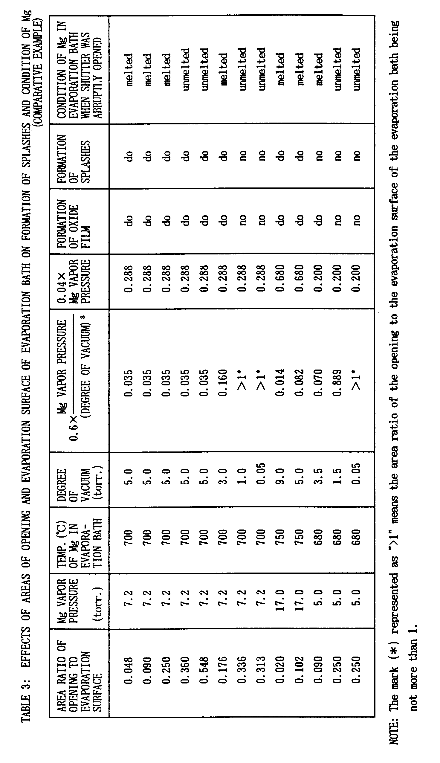
- It is noted from Tables 2 that Mg was evaporated from molten state without the formation of oxide films or splashes, when the operational conditions satisfied the relationships of





- The area ratio of the
opening 8 to the evaporation surface of theMg source 3 was adjsuted to 0.01, and the degree of vacuum was adjusted to 0.01 torr. so as to evaporate Mg without the formation of oxide films. The other conditions were the same as those in Example 4. - In this example, the splashing of the Mg source was researched in relation with the temperature of the Mg source. The results are shown in Table 4. It is noted from Table 4 that splashing was not detected when the molten Mg source was held at a temperature of 770 °C or lower. Violent splashing was detected as the rising of the temperature above 770 °C. The splahes were larger in size as the rising of the temperature, too.
TABLE 4 EFFECT OF TEMPERATURE OF MOLTEN Mg SOURCE ON SPLASHING NOTE TEMP. (°C) OF MOLTEN Mg SOURCE SPLASHING EXAMPLES OF THE PRESENT INVENTION 670 no 680 no 700 no 720 no 740 no 760 no 770 no COMPARATIVE EXAMPLES 790 do 810 do 830 do - According to the present invention as afore-mentioned, Mg is evaporated from molten state so that vapor Mg deposition can be performed under stabilized condition without fluctuations in evaporation speed. The clusters or splashes which would cause defects in vapor deposition films are suppressed by providing a reflector plate at a Mg receiving vessel or a duct extending from the vessel to the surface of a substerate sheet. Since the duct directly introduces Mg vapor toward the substrate sheet and eliminates the waseful stream of Mg vapor, Mg vapor is efficiently consumed for vapor deposition, and the position to locate the substrate sheet is determined with the high degree of freedom. When the opening area of the vessel is adjusted in relation with other operational conditions such as the evaporation surface of the Mg source, vapor pressure and the degree of vacuum, the stabilized evaporation of Mg from molten state is assured without the formation of oxide films or reaction products on the surface of the Mg source or the formation of splashes. Accordingly, vapor Mg deposition is performed under stable condition witout fluctuations in evaporation speed.
Claims (5)
- A Mg evaporation method comprising the steps of:- receiving a Mg source in a vessel having an opening,- heating said vessel at a temperature of 670 °C or higher.- evaporating Mg from molten state, while holding said vessel filled with said Mg vapor,- effusing said Mg vapor through said opening, and- carrying said Mg vapor to a substrate sheet.
- The Mg evaporation method according to Claimn 1, wherein the Mg source in the vessel is held at a temperature of 770 °C or lower.
- The Mg evaporation method according to Claim 1, wherein a reflector plate provided at the outlet of the opening is heated at a temperature of 500 °C or higher.
- The Mg evaporation method according to Claim 1, wherein the Mg vapor is introduced through a duct from the vessel to the position where the substrate sheet is located, said duct being heated at 500 °C or higher.
- A Mg evaporation method comprising the steps of:- locating an evaporation vessel having an opening in a vacuum atmosphere or a decompressed N2 atmosphere.- determining operational conditions so as to satisyfy the relationships of

 - heating said vessel so as to fill said vessel with formed Mg vapor,- effusing said Mg vapor through said opening, and- carrying said Mg vapor to a substrate sheet.
Applications Claiming Priority (3)
| Application Number | Priority Date | Filing Date | Title |
|---|---|---|---|
| JP7094333A JPH08269696A (en) | 1995-03-28 | 1995-03-28 | Method for vaporizing mg |
| JP94333/95 | 1995-03-28 | ||
| JP9433395 | 1995-03-28 |
Publications (3)
| Publication Number | Publication Date |
|---|---|
| EP0735157A2 true EP0735157A2 (en) | 1996-10-02 |
| EP0735157A3 EP0735157A3 (en) | 1997-08-27 |
| EP0735157B1 EP0735157B1 (en) | 2001-10-04 |
Family
ID=14107361
Family Applications (1)
| Application Number | Title | Priority Date | Filing Date |
|---|---|---|---|
| EP96102923A Expired - Lifetime EP0735157B1 (en) | 1995-03-28 | 1996-02-27 | Formation of magnesium vapor with high evaporation speed |
Country Status (6)
| Country | Link |
|---|---|
| US (1) | US5705226A (en) |
| EP (1) | EP0735157B1 (en) |
| JP (1) | JPH08269696A (en) |
| KR (1) | KR100287978B1 (en) |
| CN (1) | CN1070934C (en) |
| DE (1) | DE69615598T2 (en) |
Cited By (4)
| Publication number | Priority date | Publication date | Assignee | Title |
|---|---|---|---|---|
| EP0982411A3 (en) * | 1998-08-26 | 2001-02-28 | TDK Corporation | Evaporation source, apparatus and method for the preparation of organic EL device |
| DE10111515A1 (en) * | 2001-02-19 | 2002-08-14 | Fraunhofer Ges Forschung | Plasma coating device used for coating metallic strip material in the manufacture of photovoltaic cells and modules comprises a hollow cathode |
| DE102005049906A1 (en) * | 2005-10-17 | 2007-04-19 | Von Ardenne Anlagentechnik Gmbh | Method and apparatus for evaporating evaporation material |
| DE102004041846B4 (en) * | 2004-04-27 | 2007-08-02 | Von Ardenne Anlagentechnik Gmbh | Evaporation device and method for evaporating coating material |
Families Citing this family (10)
| Publication number | Priority date | Publication date | Assignee | Title |
|---|---|---|---|---|
| EP1174526A1 (en) * | 2000-07-17 | 2002-01-23 | Nederlandse Organisatie voor Toegepast Natuurwetenschappelijk Onderzoek TNO | Continuous vapour deposition |
| US8522799B2 (en) * | 2005-12-30 | 2013-09-03 | Lam Research Corporation | Apparatus and system for cleaning a substrate |
| KR20060081015A (en) * | 2005-01-06 | 2006-07-12 | 삼성에스디아이 주식회사 | Vacuum evaporator |
| US7165340B2 (en) * | 2005-02-04 | 2007-01-23 | Eastman Kodak Company | Feeding organic material to a heated surface |
| US7398605B2 (en) * | 2005-02-04 | 2008-07-15 | Eastman Kodak Company | Method of feeding particulate material to a heated vaporization surface |
| ITMI20060444A1 (en) * | 2006-03-13 | 2007-09-14 | Getters Spa | USE OF MAGNESIUM-COPPER COMPOSITIONS FOR MAGNESIUM EVAPORATION AND MAGNESIUM DISPENSERS |
| CN104078626B (en) * | 2014-07-22 | 2016-07-06 | 深圳市华星光电技术有限公司 | Heater for OLED material evaporation |
| CN104988462B (en) * | 2015-07-23 | 2017-05-31 | 京东方科技集团股份有限公司 | A kind of crucible device |
| CN112630105A (en) * | 2020-12-09 | 2021-04-09 | 中山赛特奥日用科技有限公司 | Evaporation method for simulating actual volatilization of electrical heating fragrance product |
| CN115181861A (en) * | 2022-07-20 | 2022-10-14 | 磐一(西安)装备技术有限公司 | Device for obtaining high-purity magnesium by scanning metal magnesium ingot with electron beam and purification method |
Family Cites Families (10)
| Publication number | Priority date | Publication date | Assignee | Title |
|---|---|---|---|---|
| US2793609A (en) * | 1953-01-26 | 1957-05-28 | British Dielectric Res Ltd | Means for the deposition of materials by evaporation in a vacuum |
| US2996418A (en) * | 1957-06-05 | 1961-08-15 | Gen Motors Corp | Method and apparatus for vapor depositing thin films |
| US3637421A (en) * | 1969-08-27 | 1972-01-25 | Joseph Paul Gimigliano | Vacuum vapor coating with metals of high vapor pressure |
| US5002837A (en) * | 1988-07-06 | 1991-03-26 | Kabushiki Kaisha Kobe Seiko Sho | Zn-Mg alloy vapor deposition plated metals of high corrosion resistance, as well as method of producing them |
| JPH0273960A (en) * | 1988-09-09 | 1990-03-13 | Kobe Steel Ltd | Vacuum deposition device |
| JPH02125866A (en) * | 1988-11-04 | 1990-05-14 | Kobe Steel Ltd | Device for applying alloy plating by vapor deposition |
| JPH0689418B2 (en) * | 1989-05-19 | 1994-11-09 | 宇部興産株式会社 | Continuous magnesium dissolution evaporator |
| JPH04308076A (en) * | 1991-04-03 | 1992-10-30 | Mitsubishi Heavy Ind Ltd | Vacuum deposition device for sublimable substance |
| JPH0892734A (en) * | 1994-09-22 | 1996-04-09 | Nisshin Steel Co Ltd | Evaporation of mg |
| JPH08165562A (en) * | 1994-12-12 | 1996-06-25 | Nisshin Steel Co Ltd | Method for vaporizing magnesium under stable condition and device therefor |
-
1995
- 1995-03-28 JP JP7094333A patent/JPH08269696A/en not_active Withdrawn
-
1996
- 1996-02-27 DE DE69615598T patent/DE69615598T2/en not_active Expired - Fee Related
- 1996-02-27 EP EP96102923A patent/EP0735157B1/en not_active Expired - Lifetime
- 1996-03-27 US US08/622,822 patent/US5705226A/en not_active Expired - Fee Related
- 1996-03-28 KR KR1019960008764A patent/KR100287978B1/en not_active Expired - Fee Related
- 1996-03-28 CN CN96102793A patent/CN1070934C/en not_active Expired - Fee Related
Cited By (7)
| Publication number | Priority date | Publication date | Assignee | Title |
|---|---|---|---|---|
| EP0982411A3 (en) * | 1998-08-26 | 2001-02-28 | TDK Corporation | Evaporation source, apparatus and method for the preparation of organic EL device |
| US6296894B1 (en) | 1998-08-26 | 2001-10-02 | Tdk Corporation | Evaporation source, apparatus and method for the preparation of organic El device |
| DE10111515A1 (en) * | 2001-02-19 | 2002-08-14 | Fraunhofer Ges Forschung | Plasma coating device used for coating metallic strip material in the manufacture of photovoltaic cells and modules comprises a hollow cathode |
| DE102004041846B4 (en) * | 2004-04-27 | 2007-08-02 | Von Ardenne Anlagentechnik Gmbh | Evaporation device and method for evaporating coating material |
| DE102005049906A1 (en) * | 2005-10-17 | 2007-04-19 | Von Ardenne Anlagentechnik Gmbh | Method and apparatus for evaporating evaporation material |
| WO2007045215A1 (en) * | 2005-10-17 | 2007-04-26 | Von Ardenne Anlagentechnik Gmbh | Method and apparatus for evaporating material for coatings |
| DE102005049906B4 (en) * | 2005-10-17 | 2009-12-03 | Von Ardenne Anlagentechnik Gmbh | Method and apparatus for evaporating evaporation material |
Also Published As
| Publication number | Publication date |
|---|---|
| JPH08269696A (en) | 1996-10-15 |
| DE69615598T2 (en) | 2002-10-02 |
| KR100287978B1 (en) | 2001-05-02 |
| DE69615598D1 (en) | 2001-11-08 |
| US5705226A (en) | 1998-01-06 |
| CN1070934C (en) | 2001-09-12 |
| EP0735157A3 (en) | 1997-08-27 |
| EP0735157B1 (en) | 2001-10-04 |
| KR960034458A (en) | 1996-10-22 |
| CN1137574A (en) | 1996-12-11 |
Similar Documents
| Publication | Publication Date | Title |
|---|---|---|
| US5705226A (en) | Formation of magnesium vapor with high evaporation speed | |
| KR101453583B1 (en) | Method for coating a substrate and metal alloy vacuum deposition facility | |
| US4395440A (en) | Method of and apparatus for manufacturing ultrafine particle film | |
| US4655893A (en) | Cubic boron nitride preparation utilizing a boron and nitrogen bearing gas | |
| CA1157806A (en) | Cubic boron nitride preparation | |
| US4412899A (en) | Cubic boron nitride preparation utilizing nitrogen gas | |
| KR20100126259A (en) | Industrial steam generator for depositing alloy coatings on metal strips | |
| JP2009084625A (en) | Source gas supply system and film forming apparatus | |
| US5474809A (en) | Evaporation method | |
| JP2000080464A (en) | Low thermal conductivity and heat barrier type ceramic coating, method for depositing ceramic coating and metallic parts protected by this ceramic coating | |
| JPS61213371A (en) | Crucible for deposition | |
| JPH06502450A (en) | In-situ growth method for superconducting films | |
| JP2719283B2 (en) | Knudsen cell for low temperature | |
| JPH0892734A (en) | Evaporation of mg | |
| KR20170056326A (en) | Vacuum vapor manipulator | |
| JPS6137336B2 (en) | ||
| US5132506A (en) | Vacuum evaporation apparatus and method for making vacuum evaporated sheet | |
| JP2001348660A (en) | Apparatus and method for depositing film | |
| JPS6260876A (en) | Device for vapor-depositing thin film | |
| DE102009014891B4 (en) | Device for vaporizing a material in a vacuum chamber | |
| KR950004781B1 (en) | Evaporation source for resistance heating zinc evaporation | |
| JPH02145769A (en) | Method and device for forming thin film | |
| JPH06116718A (en) | Vapor deposition plating method for sublimable material | |
| JP2004533910A (en) | Integrated phase separator for ultra-high vacuum systems | |
| JPH0688214A (en) | Vapor deposition plating method |
Legal Events
| Date | Code | Title | Description |
|---|---|---|---|
| PUAI | Public reference made under article 153(3) epc to a published international application that has entered the european phase |
Free format text: ORIGINAL CODE: 0009012 |
|
| AK | Designated contracting states |
Kind code of ref document: A2 Designated state(s): DE FR GB |
|
| PUAL | Search report despatched |
Free format text: ORIGINAL CODE: 0009013 |
|
| AK | Designated contracting states |
Kind code of ref document: A3 Designated state(s): DE FR GB |
|
| 17P | Request for examination filed |
Effective date: 19970925 |
|
| 17Q | First examination report despatched |
Effective date: 19971031 |
|
| GRAG | Despatch of communication of intention to grant |
Free format text: ORIGINAL CODE: EPIDOS AGRA |
|
| GRAG | Despatch of communication of intention to grant |
Free format text: ORIGINAL CODE: EPIDOS AGRA |
|
| GRAH | Despatch of communication of intention to grant a patent |
Free format text: ORIGINAL CODE: EPIDOS IGRA |
|
| GRAH | Despatch of communication of intention to grant a patent |
Free format text: ORIGINAL CODE: EPIDOS IGRA |
|
| GRAA | (expected) grant |
Free format text: ORIGINAL CODE: 0009210 |
|
| AK | Designated contracting states |
Kind code of ref document: B1 Designated state(s): DE FR GB |
|
| REF | Corresponds to: |
Ref document number: 69615598 Country of ref document: DE Date of ref document: 20011108 |
|
| ET | Fr: translation filed | ||
| REG | Reference to a national code |
Ref country code: GB Ref legal event code: IF02 |
|
| PGFP | Annual fee paid to national office [announced via postgrant information from national office to epo] |
Ref country code: GB Payment date: 20020227 Year of fee payment: 7 |
|
| PGFP | Annual fee paid to national office [announced via postgrant information from national office to epo] |
Ref country code: DE Payment date: 20020313 Year of fee payment: 7 |
|
| PLBI | Opposition filed |
Free format text: ORIGINAL CODE: 0009260 |
|
| PLBF | Reply of patent proprietor to notice(s) of opposition |
Free format text: ORIGINAL CODE: EPIDOS OBSO |
|
| 26 | Opposition filed |
Opponent name: VON ARDENNE ANLAGENTECHNIK GMBH Effective date: 20020702 |
|
| PG25 | Lapsed in a contracting state [announced via postgrant information from national office to epo] |
Ref country code: GB Free format text: LAPSE BECAUSE OF NON-PAYMENT OF DUE FEES Effective date: 20030227 |
|
| PLAS | Information related to reply of patent proprietor to notice(s) of opposition deleted |
Free format text: ORIGINAL CODE: EPIDOSDOBS3 |
|
| PLBB | Reply of patent proprietor to notice(s) of opposition received |
Free format text: ORIGINAL CODE: EPIDOSNOBS3 |
|
| PG25 | Lapsed in a contracting state [announced via postgrant information from national office to epo] |
Ref country code: DE Free format text: LAPSE BECAUSE OF NON-PAYMENT OF DUE FEES Effective date: 20030902 |
|
| PLCK | Communication despatched that opposition was rejected |
Free format text: ORIGINAL CODE: EPIDOSNREJ1 |
|
| GBPC | Gb: european patent ceased through non-payment of renewal fee | ||
| PLBN | Opposition rejected |
Free format text: ORIGINAL CODE: 0009273 |
|
| STAA | Information on the status of an ep patent application or granted ep patent |
Free format text: STATUS: OPPOSITION REJECTED |
|
| 27O | Opposition rejected |
Effective date: 20031217 |
|
| PG25 | Lapsed in a contracting state [announced via postgrant information from national office to epo] |
Ref country code: FR Free format text: LAPSE BECAUSE OF NON-PAYMENT OF DUE FEES Effective date: 20040430 |
|
| REG | Reference to a national code |
Ref country code: FR Ref legal event code: ST |
|
| PG25 | Lapsed in a contracting state [announced via postgrant information from national office to epo] |
Ref country code: FR Free format text: LAPSE BECAUSE OF NON-PAYMENT OF DUE FEES Effective date: 20020228 |