EP0734929B1 - Electro-hydraulic brake system - Google Patents
Electro-hydraulic brake system Download PDFInfo
- Publication number
- EP0734929B1 EP0734929B1 EP96103965A EP96103965A EP0734929B1 EP 0734929 B1 EP0734929 B1 EP 0734929B1 EP 96103965 A EP96103965 A EP 96103965A EP 96103965 A EP96103965 A EP 96103965A EP 0734929 B1 EP0734929 B1 EP 0734929B1
- Authority
- EP
- European Patent Office
- Prior art keywords
- valve
- brake
- connection
- hydraulic fluid
- pressure
- Prior art date
- Legal status (The legal status is an assumption and is not a legal conclusion. Google has not performed a legal analysis and makes no representation as to the accuracy of the status listed.)
- Expired - Lifetime
Links
Images


Classifications
-
- B—PERFORMING OPERATIONS; TRANSPORTING
- B60—VEHICLES IN GENERAL
- B60T—VEHICLE BRAKE CONTROL SYSTEMS OR PARTS THEREOF; BRAKE CONTROL SYSTEMS OR PARTS THEREOF, IN GENERAL; ARRANGEMENT OF BRAKING ELEMENTS ON VEHICLES IN GENERAL; PORTABLE DEVICES FOR PREVENTING UNWANTED MOVEMENT OF VEHICLES; VEHICLE MODIFICATIONS TO FACILITATE COOLING OF BRAKES
- B60T8/00—Arrangements for adjusting wheel-braking force to meet varying vehicular or ground-surface conditions, e.g. limiting or varying distribution of braking force
- B60T8/32—Arrangements for adjusting wheel-braking force to meet varying vehicular or ground-surface conditions, e.g. limiting or varying distribution of braking force responsive to a speed condition, e.g. acceleration or deceleration
- B60T8/321—Arrangements for adjusting wheel-braking force to meet varying vehicular or ground-surface conditions, e.g. limiting or varying distribution of braking force responsive to a speed condition, e.g. acceleration or deceleration deceleration
- B60T8/3255—Systems in which the braking action is dependent on brake pedal data
- B60T8/326—Hydraulic systems
-
- B—PERFORMING OPERATIONS; TRANSPORTING
- B60—VEHICLES IN GENERAL
- B60T—VEHICLE BRAKE CONTROL SYSTEMS OR PARTS THEREOF; BRAKE CONTROL SYSTEMS OR PARTS THEREOF, IN GENERAL; ARRANGEMENT OF BRAKING ELEMENTS ON VEHICLES IN GENERAL; PORTABLE DEVICES FOR PREVENTING UNWANTED MOVEMENT OF VEHICLES; VEHICLE MODIFICATIONS TO FACILITATE COOLING OF BRAKES
- B60T13/00—Transmitting braking action from initiating means to ultimate brake actuator with power assistance or drive; Brake systems incorporating such transmitting means, e.g. air-pressure brake systems
- B60T13/10—Transmitting braking action from initiating means to ultimate brake actuator with power assistance or drive; Brake systems incorporating such transmitting means, e.g. air-pressure brake systems with fluid assistance, drive, or release
- B60T13/66—Electrical control in fluid-pressure brake systems
- B60T13/68—Electrical control in fluid-pressure brake systems by electrically-controlled valves
- B60T13/686—Electrical control in fluid-pressure brake systems by electrically-controlled valves in hydraulic systems or parts thereof
-
- B—PERFORMING OPERATIONS; TRANSPORTING
- B60—VEHICLES IN GENERAL
- B60T—VEHICLE BRAKE CONTROL SYSTEMS OR PARTS THEREOF; BRAKE CONTROL SYSTEMS OR PARTS THEREOF, IN GENERAL; ARRANGEMENT OF BRAKING ELEMENTS ON VEHICLES IN GENERAL; PORTABLE DEVICES FOR PREVENTING UNWANTED MOVEMENT OF VEHICLES; VEHICLE MODIFICATIONS TO FACILITATE COOLING OF BRAKES
- B60T13/00—Transmitting braking action from initiating means to ultimate brake actuator with power assistance or drive; Brake systems incorporating such transmitting means, e.g. air-pressure brake systems
- B60T13/74—Transmitting braking action from initiating means to ultimate brake actuator with power assistance or drive; Brake systems incorporating such transmitting means, e.g. air-pressure brake systems with electrical assistance or drive
- B60T13/745—Transmitting braking action from initiating means to ultimate brake actuator with power assistance or drive; Brake systems incorporating such transmitting means, e.g. air-pressure brake systems with electrical assistance or drive acting on a hydraulic system, e.g. a master cylinder
-
- B—PERFORMING OPERATIONS; TRANSPORTING
- B60—VEHICLES IN GENERAL
- B60T—VEHICLE BRAKE CONTROL SYSTEMS OR PARTS THEREOF; BRAKE CONTROL SYSTEMS OR PARTS THEREOF, IN GENERAL; ARRANGEMENT OF BRAKING ELEMENTS ON VEHICLES IN GENERAL; PORTABLE DEVICES FOR PREVENTING UNWANTED MOVEMENT OF VEHICLES; VEHICLE MODIFICATIONS TO FACILITATE COOLING OF BRAKES
- B60T7/00—Brake-action initiating means
- B60T7/02—Brake-action initiating means for personal initiation
- B60T7/04—Brake-action initiating means for personal initiation foot actuated
- B60T7/042—Brake-action initiating means for personal initiation foot actuated by electrical means, e.g. using travel or force sensors
-
- B—PERFORMING OPERATIONS; TRANSPORTING
- B60—VEHICLES IN GENERAL
- B60T—VEHICLE BRAKE CONTROL SYSTEMS OR PARTS THEREOF; BRAKE CONTROL SYSTEMS OR PARTS THEREOF, IN GENERAL; ARRANGEMENT OF BRAKING ELEMENTS ON VEHICLES IN GENERAL; PORTABLE DEVICES FOR PREVENTING UNWANTED MOVEMENT OF VEHICLES; VEHICLE MODIFICATIONS TO FACILITATE COOLING OF BRAKES
- B60T8/00—Arrangements for adjusting wheel-braking force to meet varying vehicular or ground-surface conditions, e.g. limiting or varying distribution of braking force
- B60T8/26—Arrangements for adjusting wheel-braking force to meet varying vehicular or ground-surface conditions, e.g. limiting or varying distribution of braking force characterised by producing differential braking between front and rear wheels
- B60T8/266—Arrangements for adjusting wheel-braking force to meet varying vehicular or ground-surface conditions, e.g. limiting or varying distribution of braking force characterised by producing differential braking between front and rear wheels using valves or actuators with external control means
-
- B—PERFORMING OPERATIONS; TRANSPORTING
- B60—VEHICLES IN GENERAL
- B60T—VEHICLE BRAKE CONTROL SYSTEMS OR PARTS THEREOF; BRAKE CONTROL SYSTEMS OR PARTS THEREOF, IN GENERAL; ARRANGEMENT OF BRAKING ELEMENTS ON VEHICLES IN GENERAL; PORTABLE DEVICES FOR PREVENTING UNWANTED MOVEMENT OF VEHICLES; VEHICLE MODIFICATIONS TO FACILITATE COOLING OF BRAKES
- B60T8/00—Arrangements for adjusting wheel-braking force to meet varying vehicular or ground-surface conditions, e.g. limiting or varying distribution of braking force
- B60T8/32—Arrangements for adjusting wheel-braking force to meet varying vehicular or ground-surface conditions, e.g. limiting or varying distribution of braking force responsive to a speed condition, e.g. acceleration or deceleration
- B60T8/34—Arrangements for adjusting wheel-braking force to meet varying vehicular or ground-surface conditions, e.g. limiting or varying distribution of braking force responsive to a speed condition, e.g. acceleration or deceleration having a fluid pressure regulator responsive to a speed condition
- B60T8/36—Arrangements for adjusting wheel-braking force to meet varying vehicular or ground-surface conditions, e.g. limiting or varying distribution of braking force responsive to a speed condition, e.g. acceleration or deceleration having a fluid pressure regulator responsive to a speed condition including a pilot valve responding to an electromagnetic force
- B60T8/3615—Electromagnetic valves specially adapted for anti-lock brake and traction control systems
- B60T8/3655—Continuously controlled electromagnetic valves
-
- B—PERFORMING OPERATIONS; TRANSPORTING
- B60—VEHICLES IN GENERAL
- B60T—VEHICLE BRAKE CONTROL SYSTEMS OR PARTS THEREOF; BRAKE CONTROL SYSTEMS OR PARTS THEREOF, IN GENERAL; ARRANGEMENT OF BRAKING ELEMENTS ON VEHICLES IN GENERAL; PORTABLE DEVICES FOR PREVENTING UNWANTED MOVEMENT OF VEHICLES; VEHICLE MODIFICATIONS TO FACILITATE COOLING OF BRAKES
- B60T8/00—Arrangements for adjusting wheel-braking force to meet varying vehicular or ground-surface conditions, e.g. limiting or varying distribution of braking force
- B60T8/32—Arrangements for adjusting wheel-braking force to meet varying vehicular or ground-surface conditions, e.g. limiting or varying distribution of braking force responsive to a speed condition, e.g. acceleration or deceleration
- B60T8/34—Arrangements for adjusting wheel-braking force to meet varying vehicular or ground-surface conditions, e.g. limiting or varying distribution of braking force responsive to a speed condition, e.g. acceleration or deceleration having a fluid pressure regulator responsive to a speed condition
- B60T8/40—Arrangements for adjusting wheel-braking force to meet varying vehicular or ground-surface conditions, e.g. limiting or varying distribution of braking force responsive to a speed condition, e.g. acceleration or deceleration having a fluid pressure regulator responsive to a speed condition comprising an additional fluid circuit including fluid pressurising means for modifying the pressure of the braking fluid, e.g. including wheel driven pumps for detecting a speed condition, or pumps which are controlled by means independent of the braking system
- B60T8/4072—Systems in which a driver input signal is used as a control signal for the additional fluid circuit which is normally used for braking
-
- B—PERFORMING OPERATIONS; TRANSPORTING
- B60—VEHICLES IN GENERAL
- B60T—VEHICLE BRAKE CONTROL SYSTEMS OR PARTS THEREOF; BRAKE CONTROL SYSTEMS OR PARTS THEREOF, IN GENERAL; ARRANGEMENT OF BRAKING ELEMENTS ON VEHICLES IN GENERAL; PORTABLE DEVICES FOR PREVENTING UNWANTED MOVEMENT OF VEHICLES; VEHICLE MODIFICATIONS TO FACILITATE COOLING OF BRAKES
- B60T8/00—Arrangements for adjusting wheel-braking force to meet varying vehicular or ground-surface conditions, e.g. limiting or varying distribution of braking force
- B60T8/32—Arrangements for adjusting wheel-braking force to meet varying vehicular or ground-surface conditions, e.g. limiting or varying distribution of braking force responsive to a speed condition, e.g. acceleration or deceleration
- B60T8/34—Arrangements for adjusting wheel-braking force to meet varying vehicular or ground-surface conditions, e.g. limiting or varying distribution of braking force responsive to a speed condition, e.g. acceleration or deceleration having a fluid pressure regulator responsive to a speed condition
- B60T8/48—Arrangements for adjusting wheel-braking force to meet varying vehicular or ground-surface conditions, e.g. limiting or varying distribution of braking force responsive to a speed condition, e.g. acceleration or deceleration having a fluid pressure regulator responsive to a speed condition connecting the brake actuator to an alternative or additional source of fluid pressure, e.g. traction control systems
- B60T8/4809—Traction control, stability control, using both the wheel brakes and other automatic braking systems
- B60T8/4827—Traction control, stability control, using both the wheel brakes and other automatic braking systems in hydraulic brake systems
Definitions
- the invention relates to an electro-hydraulic brake system for Motor vehicles with an actuable by a brake pedal Brake cylinder and a pressureless reservoir for hydraulic fluid, a braking device coupled to a vehicle wheel, which can be connected to the brake cylinder in order the braking device with pressurized hydraulic fluid to pressurize a pressurized hydraulic fluid supplying source associated with the braking device can be brought to the braking device with pressure
- an electronic control device which with a sensor for detecting the Brake pedal occurring static and dynamic states is connected and signals emitted by the sensor for generation of control signals for a control valve arrangement.
- the Braking the motor vehicle required braking energy an electrically operated braking system is provided.
- the brake system also has a hydraulic auxiliary brake system for immediate application of the brakes.
- the field of application of such an electro-hydraulic brake system includes anti-lock control, anti-slip control, electronic Brake force distribution and driving dynamics regulations.
- the driver's request for an electrically operated brake system on the brake pedal with sensors and in the form of electrical Signals are supplied to the electronic control such systems are also referred to as "brake-by-wire".
- For the redundant hydraulic emergency system is conventional direct via a brake pressure sensor and hydraulic lines To establish a connection between the brake pedal and the brakes, which is also called “push-through”. This requires a switching device so that during normal operation the in brake pressure generated in the electrical system, and if present a fault or failure of the electrical system in the hydraulic auxiliary system generated brake pressure on the brakes is transmitted.
- DE 42 29 041 A1 describes a brake control system for a Vehicle known in addition to an electric Brake system is provided a mechanical brake system that automatically operated when an unexpected electrical An error has occurred in the electrical braking system.
- the switching device is designed so that the connection with the mechanical braking system in the basic position, i.e. when the solenoid valve is not actuated electrically, is set.
- a "push-through" capable of this concept electro-hydraulic brake system is also from US 721,019 known.
- a hydraulic brake system is known from WO 96/11129, where the output of a Master cylinder is interrupted and the brakes of one High pressure hydraulic source are operated.
- the movements of the brake pedal sensed and by means of a control unit Solenoid valves actuated.
- Solenoid valves actuated.
- a direct solenoid valve can be used Connection between the master brake cylinder and the brakes be opened or blocked.
- the electrical Brake system can use the valves with the high pressure source connect each brake, separate each brake from other lines or a connection between each brake and a reservoir provide.
- a disadvantage of these known systems is that the switching device between the wheel brake and the electro-hydraulic Unit is arranged. As a consequence, that in the event of leaks and / or electrical Malfunctions defective switching device the proper function the braking system is not guaranteed and in extreme cases can even lead to total failure of the "push-through".
- the invention is therefore based on the object while avoiding the aforementioned disadvantages of a "push-through" capable electro-hydraulic Brake system to develop the high safety requirements fair and with a proportionate can be produced at low cost.
- control valve assembly by an electrically operated Four port valve with four valve positions formed, one of the four valve positions an unactuated Position and the valve in the three other positions by control signals from the electronic control device is feasible.
- a first connection of the valve with the Braking device a second connection of the valve with the Brake cylinder, a third connection of the valve with the unpressurized Hydraulic fluid reservoir, and a fourth port of the valve with the hydraulic fluid supplying the pressure Source connected.
- the valve has a pressure control input on it is connected to the first port of the valve to the valve to bring it into its unactuated position.
- This shift of the valve member against the force of the actuating electromagnet of the valve leads to an increase in the current that flows through the electromagnetic coil. This current increase can measured and measured in the electronic control device become.
- Valve has a pressure control input connected to the second port of the valve is connected to the valve in its unactuated Position.
- the electro-hydraulic brake system for motor vehicles Control valve arrangement by a first electrically operable Valve with three connections and three valve positions, as well a second electrically operated valve with three connections and two valve positions are formed, one valve position each of the first valve and a position of the second Valve are an unactuated position, and the first and that second valve in the other positions by control signals can be brought by the electronic control device.
- a second connection is a first connection of the second valve with the braking device, a second Connection of the second valve with a first connection of the first valve, a third connection of the second valve with the brake cylinder, a second connection of the first valve with the unpressurized reservoir for hydraulic fluid, and a third Connection of the first valve with the pressurized hydraulic fluid supplying source connected.
- a third training are a first connection of the first valve with the braking device, a second connection of the first valve with a first connection of the second valve and with the brake cylinder, a third connection of the first Valve with the supply of hydraulic fluid under pressure Source, and a second port of the second valve to the unpressurized reservoir for hydraulic fluid are connected.
- pressure control inputs on the first valve for the determination of the pressure in the braking device or Increased security may be provided.
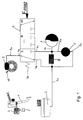
- the electrohydraulic brake system according to FIG. 1 has one Brake pedal 1 and a connected travel simulator 2, who has a sensor 3 for detecting the driver's request, the for example an electrical one derived from the actuation Outputs and / or force signal.
- the driver request becomes one transmit electronic control unit, not shown here, evaluated there and for generating electrical control signals to control a valve 4 and a hydraulic pump 5 used.
- the brake pressure required for braking is determined by one unit consisting of the preferably driven by an electric motor Pump 5 and a pressure reservoir 6 provided.
- a pressure relief valve 8 is arranged, which the pressure in the memory 6 to a predetermined limit limited. So that the pressure in the memory 6 is maintained, the pump 5 is designed to hold pressure, which is suitable by check valves or a self-locking drive is achieved.
- An electromagnetically operated proportional valve 4 which has connections 4a, 4b and 4c, serves as the actuator.
- the connection 4a is connected via line 9a to a wheel brake 9, the connection 4b via line 7a to the reservoir 7 and the connection 4c to the outlet 6a of the pressure accumulator 6.
- the proportional valve 4 In the non-actuated, that is, de-energized state, the proportional valve 4 remains in its basic position I under the action of a spring 4e and is actuated according to the magnetic force F mag resulting from the energization, which is opposite to the force of the spring 4d, into the switching positions II. And III . transferred.
- the connections 4a and 4b are directly connected to each other while port 4c is blocked is.
- the wheel brake 9 is directly connected to the reservoir 7 connected so that a pending at the wheel brake 9 Brake pressure is completely reduced.
- the valve is located 4 in the second switching position II., Then the connections 4a, 4b and 4c are each blocked, as a result of which a wheel brake 9 Brake pressure is maintained. If the valve 4 in switch position III. are the connections 4a and 4c connected and the connection 4b is blocked.
- the pressure in the wheel brake 9 to that in the pressure accumulator 6 existing pressure level built up.
- the electrohydraulic shown in Fig. 2 Brake system is compared to the system shown in Fig. 1 extended a "push-through” option.
- the brake pedal is 1 with a brake pressure sensor 11 coupled to the reservoir 7 mechanically connected from which an auxiliary brake circuit line 11a going out.
- an electromagnetically operated Changeover valve 12 In line 9a between port 4a of the proportional valve 4 and the wheel brake 9 is an electromagnetically operated Changeover valve 12 with three connections 12a, 12b, 12c arranged.
- the connection 12a is with the wheel brake 9
- the connection 12b with the connection 4a of the proportional valve 4 and the connection 12c is connected to the brake pressure transmitter via line 11a.
- the changeover valve 12 takes under the spring 12d his (shown) basic position I. in which the connections 12a and 12c are connected together and the connection 12b is locked so that the wheel brake 9 from the brake transmitter 11 is pressurized.
- actuation position II the connections 12a and 12b are connected to each other and the Port 12c is blocked, so that the pressure modulation in the Wheel brake 9 consisting of the electro-hydraulic unit Pump 5, pressure accumulator 6 and proportional valve 4 takes place.
- valve 4 has a pressure control line 4f, so that the pressure in the wheel brake 9 in addition to or instead of the force of the spring 4e acts to the valve 4 in its shown To transfer basic position I. and / or to hold it there.
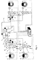
- FIG. 3 an electro-hydraulic brake system is shown at the pressure supply for the brakes 9 of the front wheels VR, VL and the brakes 8 of the rear wheels HR, HL each by one Provided via a pump 5 pressure accumulator 6 becomes.
- HL As actuators for modulating the brake pressure in the Brakes 9 of the rear axle HR, HL each serve three-three-way proportional valves 4, whereas for the brakes 9 of the front axle VR, VL the "push-through" capable four-four-way proportional valves 14 are used, which are connected to the auxiliary brake circuit 11a are connected.
- the "push-through” can here on the brakes 9 of the front wheels VR, VL take place because of this due to the dynamic Axle load distribution when braking is the predominant Braking force share is transmitted. Likewise, the "push-through” for the wheel brakes 9 of the driven vehicle axle be interpreted. When using the “push-through” only on the The brake pressure sensor can drive wheels of one axle VR, VL or HR, HL 11 designed to supply the auxiliary circuit 11a simpler what has a favorable effect on costs and space requirements.
- Switch position IV Forms the basic position in which the valve 14 in the de-energized state under the action of the spring 4e remains. In this basic position IV. Is the connection 14a directly connected to the connection 4a, so that the wheel brake 9 on the auxiliary brake circuit 11a is connected. Is that Valve 4, however, in one of the switching positions I., II. And III. so the connection 14a is always blocked.
- the power supply of the proportional valve 14 can also switched off when a fault is detected in the electro-hydraulic part be so that automatically switched to position IV is and a braking from the auxiliary brake circuit 11a becomes.
- the proportional valve has a further safety feature 14 via a pressure control line 14f, so that the pressure in the wheel brake 9 additive to or instead of the force of the spring 4e acts to transfer the valve 14 into its basic position IV and / or keep there.
- pressure feedback designated measure is achieved that the valve 14th is also in the event of a defect in the spring 4e to assume his "Push-Through" basic position IV.
- the brakes 9 of the front wheels VR, VL can also be actuated, so that the "push-through" on all vehicle wheels VR, VL, HR, HL works, which makes sense for all-wheel drive vehicles.
- an electronic control unit ECU shown, via a Sensor 3 detects the driver's braking request in order to Control signals for the control valves 4, 14 and the electric motor operated pump storage unit 5, 6 implement.
- Every wheel brake must be able to regulate with the highest possible quality 9 sensors 21 available, which provide feedback on the deliver current brake pressure. So always in memory 6 a sufficient pressure level is available, too the pressure at the memory outputs 6a is monitored by sensors 22, to control the reloading process by means of the pump 5.
- the detection of the wheel speed behavior by sensors 10 is used to do so, in the electronic control unit ECU the pressure on the Measure and modulate brakes 9 in line 9a as precisely as possible to be able to.
- the "push-through” option requires an electromagnetic one controlled shut-off valve 12, which in the connecting line 7a between reservoir 7 and pump inlet side 5a or Port 4b of the proportional valve 4 is arranged.
- the auxiliary brake circuit 11a is arranged, which also with the pump inlet side 5a or the connection 4b of the proportional valve 4 is connected.
- the shut-off valve 12 has two switching positions I. and II., which are designed so that the connection 7a in the de-energized idle state of the shut-off valve 12 locked and in its actuated State is opened. Since both the proportional valve 4 as well as the shut-off valve 12 in the event of a failure or a shutdown the basic position of the power supply I. take, the wheel brake 9 is in this case via the auxiliary brake circuit 11a operable.
- the brake system shown in Fig. 4 is instead of one Two-two-way shut-off valve 12 also by means of a three-two-way switch valve executable, which is the pump inlet side 5a or the connection 4b of the proportional valve 4 either with the auxiliary brake circuit 11a or with the reservoir outlet 7a connects, the connection to the auxiliary brake circuit 11a as currentless rest position is designed.
- System security becomes 12 necessary switching signals in particular in the embodiment corresponding to FIG. 3 increased because the probability of occurrence of switching errors, which can arise from external interference, among other things, is significantly reduced.
Description
Die Erfindung betrifft eine elektrohydraulische Bremsanlage für Kraftfahrzeuge mit einem durch ein Bremspedal betätigbaren Bremszylinder und einem drucklosen Reservoir für Hydraulikfluid, einer mit einem Fahrzeugrad gekoppelten Bremseinrichtung, die mit dem Bremszylinder in Verbindung bringbar ist, um die Bremseinrichtung mit unter Druck stehendem Hydraulikfluid zu beaufschlagen, einer unter Druck stehendes Hydraulikfluid liefernden Quelle, die mit der Bremseinrichtung in Verbindung bringbar ist, um die Bremseinrichtung mit unter Druck stehendem Hydraulikfluid zu beaufschlagen, und einer elektronischen Steuereinrichtung, die mit einem Sensor zur Erfassung von an dem Bremspedal auftretenden statischen und dynamischen Zuständen verbunden ist und von dem Sensor abgegebene Signale zur Erzeugung von Steuersignalen für eine Steuerventilanordnung heranzieht.The invention relates to an electro-hydraulic brake system for Motor vehicles with an actuable by a brake pedal Brake cylinder and a pressureless reservoir for hydraulic fluid, a braking device coupled to a vehicle wheel, which can be connected to the brake cylinder in order the braking device with pressurized hydraulic fluid to pressurize a pressurized hydraulic fluid supplying source associated with the braking device can be brought to the braking device with pressure To apply hydraulic fluid, and an electronic control device, which with a sensor for detecting the Brake pedal occurring static and dynamic states is connected and signals emitted by the sensor for generation of control signals for a control valve arrangement.
Bei einer solchen elektrohydraulischen Bremsanlage wird die zur Abbremsung des Kraftfahrzeugs erforderliche Bremsenergie durch ein elektrisch betätigtes Bremssystem bereitgestellt. Um das Fahrzeug bei einem unerwarteten Ausfall des elektrisch betätigten Bremssystems mit einer Mindestverzögerung abzubremsen, weist die Bremsanlage zusätzlich ein hydraulisches Hilfsbremssystem zur unmittelbaren Betätigung der Bremsen auf.In such an electrohydraulic brake system, the Braking the motor vehicle required braking energy an electrically operated braking system is provided. To do that Vehicle in the event of an unexpected failure of the electrically operated Braking system with a minimum deceleration, the brake system also has a hydraulic auxiliary brake system for immediate application of the brakes.
Das Anwendungsgebiet einer solchen elektrohydraulischen Bremsanlage umfaßt Antiblockierregelung, Antischlupfregelung, elektronische Bremskraftverteilung sowie fahrdynamische Regelungen. The field of application of such an electro-hydraulic brake system includes anti-lock control, anti-slip control, electronic Brake force distribution and driving dynamics regulations.
Da bei einer elektrisch betätigten Bremsanlage der Fahrerwunsch am Bremspedal mit Sensoren erfaßt und in Form von elektrischen Signalen der elektronischen Steuerung zugeführt wird, werden derartige Systeme auch als "Brake-by-Wire" bezeichnet. Für das redundante hydraulische Notsystem ist in herkömmlicher Weise über einen Bremsdruckgeber sowie Hydraulikleitungen eine direkte Verbindung zwischen Bremspedal und den Bremsen herzustellen, was auch die Bezeichnung "Push-Through" trägt. Dies erfordert eine Umschalteinrichtung, so daß bei normalem Betrieb der in dem elektrischen System erzeugte Bremsdruck, und bei Vorliegen eines Fehlers oder Ausfall des elektrischen Systems der in dem hydraulischen Hilfssystem erzeugte Bremsdruck an die Bremsen übertragen wird.The driver's request for an electrically operated brake system on the brake pedal with sensors and in the form of electrical Signals are supplied to the electronic control such systems are also referred to as "brake-by-wire". For the redundant hydraulic emergency system is conventional direct via a brake pressure sensor and hydraulic lines To establish a connection between the brake pedal and the brakes, which is also called "push-through". This requires a switching device so that during normal operation the in brake pressure generated in the electrical system, and if present a fault or failure of the electrical system in the hydraulic auxiliary system generated brake pressure on the brakes is transmitted.
Aus der DE 42 29 041 A1 ist ein Bremssteuersystem für ein Fahrzeug bekannt, bei dem zusätzlich zu einem elektrischen Bremssystem ein mechanisches Bremssystem vorgesehen ist, das automatisch betätigt wird, wenn ein unerwarteter elektrischer Fehler in dem elektrischen Bremssystem aufgetreten ist. Dazu wird ein elektromagnetisch betätigtes Drei-Zwei-Wege-Ventil derart umgeschaltet, daß die Bremsen entweder nur mit dem mechanischen Bremssystem oder nur mit dem elektrischen Bremssystem verbunden sind. Dabei ist die Umschalteinrichtung so ausgelegt, daß die Verbindung mit dem mechanischen Bremssystem in der Grundposition, also bei elektrisch nicht betätigtem Magnetventil, eingestellt wird.DE 42 29 041 A1 describes a brake control system for a Vehicle known in addition to an electric Brake system is provided a mechanical brake system that automatically operated when an unexpected electrical An error has occurred in the electrical braking system. To becomes an electromagnetically operated three-way valve switched so that the brakes either only with the mechanical Braking system or only with the electric braking system are connected. The switching device is designed so that the connection with the mechanical braking system in the basic position, i.e. when the solenoid valve is not actuated electrically, is set.
Ein nach diesem Konzept ausgerüstetes "Push-Through"-fähiges elektrohydraulisches Bremssystem ist auch aus der US 721,019 bekannt. A "push-through" capable of this concept electro-hydraulic brake system is also from US 721,019 known.
Aus der WO 96/11129 ist ein hydraulisches Bremssystem bekannt, bei dem während eines normalen Bremsbetriebs der Ausgang eines Hauptbremszylinders unterbrochen ist und die Bremsen von einer Hochdruckhydraulikquelle betätigt werden. Dabei werden die Bewegungen des Bremspedals sensiert und mittels eines Steuergerätes Magnetventile betätigt. Bei einem Ausfall der elektronischen Steuerung wird zwischen dem Hauptbremszylinder und den Bremsen eine direkte hydraulische Verbindung hergestellt, über die die Bremsen manuell betätigt werden können ("Push-Trough"-Mode). Dabei kann mittels verschiedener Magnetventile eine direkte Verbindung zwischen dem Hauptbremszylinder und den Bremsen geöffnet bzw. gesperrt werden. Für den Betrieb des elektrischen Bremssystems können die Ventile die Hochdruckquelle mit jeder Bremse verbinden, jede Bremse von anderen Leitungen trennen oder eine Verbindung zwischen jeder Bremse und einem Vorratsbehälter bereitstellen. A hydraulic brake system is known from WO 96/11129, where the output of a Master cylinder is interrupted and the brakes of one High pressure hydraulic source are operated. The movements of the brake pedal sensed and by means of a control unit Solenoid valves actuated. In the event of failure of the electronic Control is between the master cylinder and the Brakes made a direct hydraulic connection over that the brakes can be operated manually ("push-through" mode). A direct solenoid valve can be used Connection between the master brake cylinder and the brakes be opened or blocked. For the operation of the electrical Brake system can use the valves with the high pressure source connect each brake, separate each brake from other lines or a connection between each brake and a reservoir provide.
Als Nachteil bei diesen bekannten Systemen erweist sich, daß die Umschalteinrichtung zwischen der Radbremse und der elektrohydraulischen Einheit angeordnet ist. Dies hat zur Folge, daß bei einer infolge von Undichtigkeiten und/oder elektrischen Störungen defekten Umschalteinrichtung die ordnungsgemäße Funktion des Bremssystems nicht gewährleistet ist und im Extremfall sogar zum Totalausfall des "Push-Through" führen kann. A disadvantage of these known systems is that the switching device between the wheel brake and the electro-hydraulic Unit is arranged. As a consequence, that in the event of leaks and / or electrical Malfunctions defective switching device the proper function the braking system is not guaranteed and in extreme cases can even lead to total failure of the "push-through".
Zur Verringerung dieses Risikos besteht zwar die Möglichkeit die Umschalteinrichtungen redundant für jedes über den "Push-Through" abzubremsende Fahrzeugrad auszuführen. Dies wirkt sich jedoch nachteilig auf die Kosten und den Bedarf an Einbauraum aus, da zwei Umschalteinrichtungen benötigt werden, um durch den "Push-Through" zumindest die Bremsen der vorderen und/oder angetriebenen Fahrzeugachse zu betätigen. Wenn alle Fahrzeugräder über den "Push-Through" abzubremsen sind, treten diese Nachteile besonders deutlich zutage.There is a possibility to reduce this risk the switching devices redundant for each via the "push-through" vehicle wheel to be braked. This affects however, disadvantageous in terms of costs and the need for installation space out, since two switching devices are required to pass through the "push-through" at least the brakes of the front and / or to actuate the driven vehicle axle. If all vehicle wheels are to be braked via the "push-through", they occur Disadvantages are particularly evident.
Falls aus Gründen der Einsparung elektrischer Energie die Umschalteinrichtung zur Deaktivierung des "Push-Through" immer nur bei Beginn eines elektrischen Bremsvorganges betätigt wird, besteht aufgrund der Anordnung der Umschaltrichtung zwischen Radbremse und elektrohydraulischer Einheit der Nachteil, daß Umschaltzeiten zu einem zeitlich verzögerten Druckaufbau an der Radbremse führen, was sich negativ auf die Leistungsfähigkeit des Systems auswirkt.If, for reasons of saving electrical energy, the switching device to deactivate the "push-through" always is only actuated at the start of an electrical braking process, exists due to the arrangement of the switching direction between Wheel brake and electro-hydraulic unit the disadvantage that Switchover times to a time-delayed build-up of pressure on the Wheel brake lead, which negatively affects performance of the system.
Der Erfindung liegt daher die Aufgabe zugrunde unter Vermeidung der vorgenannten Nachteile eine "Push-Through"-fähige elektrohydraulische Bremsanlage zu entwickeln, die hohen Sicherheitsanforderungen gerecht wird und mit einem verhältnismäßig geringen Kostenaufwand herstellbar ist.The invention is therefore based on the object while avoiding the aforementioned disadvantages of a "push-through" capable electro-hydraulic Brake system to develop the high safety requirements fair and with a proportionate can be produced at low cost.
Zur Lösung dieser Aufgabe ist die eingangs genannte Bremsanlage
durch die Merkmale des kennzeichnenden Teils des Anspruchs 1
gekennzeichnet. Bei einer bevorzugten Ausführungsform der Erfindung
ist die Steuerventilanordnung durch ein elektrisch betätigbares
Ventil mit vier Anschlüssen und vier Ventilstellungen
gebildet, wobei eine der vier Ventilstellungen eine unbetätigte
Stellung ist und das Ventil in die drei anderen Stellungen
durch Steuersignale von der elektronischen Steuereinrichtung
bringbar ist. To solve this problem is the brake system mentioned above
by the features of the characterizing part of
Insbesondere sind dabei ein erster Anschluß des Ventils mit der Bremseinrichtung ein zweiter Anschluß des Ventils mit dem Bremszylinder, ein dritter Anschluß des Ventils mit dem drucklosen Reservoir für Hydraulikfluid, und ein vierter Anschluß des Ventils mit der unter Druck stehendes Hydraulikfluid liefernden Quelle verbunden.In particular, a first connection of the valve with the Braking device a second connection of the valve with the Brake cylinder, a third connection of the valve with the unpressurized Hydraulic fluid reservoir, and a fourth port of the valve with the hydraulic fluid supplying the pressure Source connected.
Zur Einsparung eines Sensors in der Bremseinrichtung zur Erfassung des dort herrschenden Hydraulikdrucks weist bei dieser Ausführungsform das Ventil einen Drucksteuereingang auf, der mit dem ersten Anschluß des Ventils verbunden ist, um das Ventil in seine unbetätigte Stellung zu bringen. Diese Verschiebung des Ventilgliedes gegen die Kraft des Betätigungselektromagneten des Ventils führt zu einer Erhöhung des Stroms, der durch die Elektromagnetspule fließt. Diese Stromerhöhung kann gemessen und in der elektronischen Steuereinrichtung gemessen werden.To save a sensor in the braking device for detection the hydraulic pressure prevailing there indicates this Embodiment, the valve has a pressure control input on it is connected to the first port of the valve to the valve to bring it into its unactuated position. This shift of the valve member against the force of the actuating electromagnet of the valve leads to an increase in the current that flows through the electromagnetic coil. This current increase can measured and measured in the electronic control device become.
Um auch bei defekter Ansteuerung oder Rückstellung des Ventils sicherstellen zu können, daß eine Betätigung der Bremseinrichtung über den Bremszylinder jederzeit möglich ist, weist das Ventil einen Drucksteuereingang auf, der mit dem zweiten Anschluß des Ventils verbunden ist, um das Ventil in seine unbetätigte Stellung zu bringen.To even if the control is defective or reset to be able to ensure that an actuation of the braking device is possible at any time via the brake cylinder Valve has a pressure control input connected to the second port of the valve is connected to the valve in its unactuated Position.
Gemäß zwei weiteren elektrohydraulischen Bremsanlagen für Kraftfahrzeuge ist die Steuerventilanordnung durch ein erstes elektrisch betätigbares Ventil mit drei Anschlüssen und drei Ventilstellungen, sowie ein zweites elektrisch betätigbares Ventil mit drei Anschlüssen und zwei Ventilstellungen gebildet ist, wobei jeweils eine Ventilstellung des ersten Ventils und eine Stellung des zweiten Ventils eine unbetätigte Stellung sind, und das erste und das zweite Ventil in die jeweils anderen Stellungen durch Steuersignale von der elektronischen Steuereinrichtung bringbar sind. According to two others is the electro-hydraulic brake system for motor vehicles Control valve arrangement by a first electrically operable Valve with three connections and three valve positions, as well a second electrically operated valve with three connections and two valve positions are formed, one valve position each of the first valve and a position of the second Valve are an unactuated position, and the first and that second valve in the other positions by control signals can be brought by the electronic control device.
Dabei sind bei einer zweiten Ausbildung ein erster Anschluß des zweiten Ventils mit der Bremseinrichtung, ein zweiter Anschluß des zweiten Ventils mit einem ersten Anschluß des ersten Ventils, ein dritter Anschluß des zweiten Ventils mit dem Bremszylinder, ein zweiter Anschluß des ersten Ventils mit dem drucklosen Reservoir für Hydraulikfluid, und ein dritter Anschluß des ersten Ventils mit der unter Druck stehendes Hydraulikfluid liefernden Quelle verbunden.A second connection is a first connection of the second valve with the braking device, a second Connection of the second valve with a first connection of the first valve, a third connection of the second valve with the brake cylinder, a second connection of the first valve with the unpressurized reservoir for hydraulic fluid, and a third Connection of the first valve with the pressurized hydraulic fluid supplying source connected.
Bei einer dritten Ausbildung sind ein erster Anschluß des ersten Ventils mit der Bremseinrichtung, ein zweiter Anschluß des ersten Ventils mit einem ersten Anschluß des zweiten Ventils und mit dem Bremszylinder, ein dritter Anschluß des ersten Ventils mit der unter Druck stehendes Hydraulikfluid liefernden Quelle, und ein zweiter Anschluß des zweiten Ventils mit dem drucklosen Reservoir für Hydraulikfluid verbunden sind.In a third training are a first connection of the first valve with the braking device, a second connection of the first valve with a first connection of the second valve and with the brake cylinder, a third connection of the first Valve with the supply of hydraulic fluid under pressure Source, and a second port of the second valve to the unpressurized reservoir for hydraulic fluid are connected.
Auch hier können Drucksteuereingänge an dem ersten Ventil für die Feststellung des Drucks in der Bremseinrichtung oder zur Erhöhung der Sicherheit vorgesehen sein.Here too, pressure control inputs on the first valve for the determination of the pressure in the braking device or Increased security may be provided.
Die Erfindung und deren Vorteile wird im folgenden anhand der beigefügten Zeichnungen näher erläutert. Es zeigen:
- Fig. 1
- ein elektrohydraulisches Bremssystem ohne "Push-Through",
- Fig. 2
- eine "Push-Through"-fähige elektrohydraulische Bremsanlage,
- Fig. 3
- eine Ausführungsform einer erfindungsgemäßen elektrohydraulischen Bremsanlage mit "Push-Through", und
- Fig. 4
- eine elektrohydraulische Bremsanlage mit "Push-Through".
- Fig. 1
- an electro-hydraulic brake system without "push-through",
- Fig. 2
- a "push-through" capable electro-hydraulic brake system,
- Fig. 3
- an embodiment of an electro-hydraulic brake system according to the invention with "push-through", and
- Fig. 4
- an electro-hydraulic brake system with "push-through".
Das elektrohydraulische Bremssystem gemäß Fig. 1 weist ein
Bremspedal 1 sowie einen damit verbundenen Wegsimulator 2 auf,
der einen Sensor 3 zur Erfassung des Fahrerwunsches hat, der
beispielsweise ein aus der Betätigung abgeleitetes elektrisches
Weg- und/oder Kraftsignal abgibt. Der Fahrerwunsch wird zu einer
hier nicht dargestellten elektronischen Steuereinheit übertragen,
dort ausgewertet und zur Erzeugung elektrischer Steuersignale
zur Ansteuerung eines Ventils 4 und einer Hydraulikpumpe
5 herangezogen.The electrohydraulic brake system according to FIG. 1 has one
Der zum Bremsen erforderliche Bremsdruck wird durch eine Einheit
bestehend aus der vorzugsweise elektromotorisch angetriebenen
Pumpe 5 und einem Druckspeicher 6 bereitgestellt. Dazu
ist die Eingangsseite 5a der Pumpe 5 über eine Leitung 7a mit
einem Reservoir 7 verbunden, um Hydraulikfluid anzusaugen, während
die Ausgangsseite 5b der Pumpe 5 eine direkte Verbindung
mit dem Anschluß 6a des Druckspeichers 6 aufweist. Zum Schutz
des Systems ist zwischen der Eingangsseite 5a und der Ausgangsseite
5b der Pumpe 5 ein Druckbegrenzungsventil 8 angeordnet,
welches den Druck im Speicher 6 auf einen vorgegebenen Grenzwert
limitiert. Damit der Druck im Speicher 6 gehalten wird,
ist die Pumpe 5 druckhaltend ausgeführt, was in geeigneter Weise
durch Rückschlagventile oder einen selbsthemmenden Antrieb
erreicht wird.The brake pressure required for braking is determined by one unit
consisting of the preferably driven by an
Als Stellglied dient ein elektromagnetisch betätigtes Proportionalventil
4, welches Anschlüsse 4a, 4b und 4c aufweist. Der
Anschluß 4a ist über die Leitung 9a mit einer Radbremse 9, der
Anschluß 4b über die Leitung 7a mit dem Reservoir 7 und der Anschluß
4c mit dem Ausgang 6a des Druckspeichers 6 verbunden. In
unbetätigtem, also stromlosen Zustand verharrt das Proportionalventil
4 unter Krafteinwirkung einer Feder 4e in seiner
Grundstellung I. und wird bei Betätigung gemäß der aus der Bestromung
resultierenden Magnetkraft Fmag, die der Kraft der Feder
4d entgegengerichtet ist, in die Schaltstellungen II. und
III. überführt. An electromagnetically operated
In der ersten Schaltstellung I. stehen die Anschlüsse 4a und 4b
direkt miteinander in Verbindung, während der Anschluß 4c gesperrt
ist. Dadurch ist die Radbremse 9 direkt mit dem Reservoir
7 verbunden, so daß ein an der Radbremse 9 anstehender
Bremsdruck vollständig abgebaut wird. Befindet sich das Ventil
4 in der zweiten Schaltstellung II., so sind die Anschlüsse 4a,
4b und 4c jeweils gesperrt, wodurch ein an der Radbremse 9 anstehender
Bremsdruck gehalten wird. Wenn sich das Ventil 4 in
der Schaltstellung III. befindet, sind die Anschlüsse 4a und 4c
miteinander verbunden und der Anschluß 4b ist gesperrt. Dabei
wird der Druck in der Radbremse 9 auf das im Druckspeicher 6
vorhandene Druckniveau aufgebaut.In the first switching position I., the
Durch geeignete Ansteuerung des Proportionalventils 4 ist es
möglich, zwischen den Schaltstellungen I., II. und III. so umzuschalten,
daß jeder gewünschte Druckverlauf an der Radbremse
9 einstellbar ist. Damit erlaubt ein solches Konzept nicht nur
die Umsetzung eines Bremswunsches des Fahrerzeugführers, sondern
bei Vorhandensein entsprechender Sensoren, insbesondere
der Sensoren 10 zur Erfassung des Raddrehzahlverhaltens, sind
auch Antiblockierregelung, Antischlupfregelung, elektronische
Bremskraftverteilung und fahrdynamische Regelungen durchführbar.It is by suitable control of the
Das in Fig. 2 gezeigte elektrohydraulische
Bremssystem ist gegenüber der in Fig. 1 dargestellten Anlage um
eine "Push-Through"-Option erweitert. Dazu ist das Bremspedal 1
mit einem an das Reservoir 7 gekoppelten Bremsdruckgeber 11 mechanisch
verbundene von dem ein Hilfsbremskreiseleitung 11a
ausgeht.The electrohydraulic shown in Fig. 2
Brake system is compared to the system shown in Fig. 1
extended a "push-through" option. The brake pedal is 1
with a
In der Leitung 9a zwischen dem Anschluß 4a des Proportionalventils
4 und der Radbremse 9 ist ein elektromagnetisch betätigtes
Umschaltventil 12 mit drei Anschlüssen 12a, 12b, 12c angeordnet.
Der Anschluß 12a ist mit der Radbremse 9, der Anschluß 12b
mit dem Anschluß 4a des Proportionalventils 4 und der Anschluß
12c ist über die Leitung 11a mit dem Bremsdruckgeber verbunden. In line 9a between
Im stromlosen Zustand nimmt das Umschaltventil 12 unter der Feder
12d seine (gezeigte) Grundstellung I. ein, in der die Anschlüsse
12a und 12c miteinander verbunden sind und der Anschluß
12b gesperrt ist, so daß die Radbremse 9 vom Bremsgeber
11 mit Druck beaufschlagt wird. In der Betätigungsstellung II.
sind die Anschlüsse 12a und 12b miteinander verbunden und der
Anschluß 12c ist gesperrt, so daß die Druckmodulation in der
Radbremse 9 durch die elektrohydraulische Einheit bestehend aus
Pumpe 5, Druckspeicher 6 sowie Proportionalventil 4 erfolgt.In the de-energized state, the
Damit ist gewährleistet, daß die Radbremse 9 bei einem Ausfall
der Versorgungsspannung stets über den Bremsdruckgeber 11 betätigbar
ist. Es besteht auch die Möglichkeit bei Erkennung eines
Fehlers im elektrohydraulischen Teil auf den Hilfsbremskreis
11a umzuschalten. Wenn die elektrische Versorgung des Umschaltventils
in seiner betätigten Stellung ausfällt und das Zurückholen
in die gezeigte Grundstellung aus irgendwelchen Gründen
verhindert ist, kann jedoch weder direkt, d.h. über den Hilfsbremskreis
114, noch elektrohydraulisch gebremst werden.This ensures that the
Des weiteren weist das Ventil 4 eine Drucksteuerleitung 4f auf,
so daß der Druck in der Radbremse 9 zusätzlich zur oder anstelle
der Kraft der Feder 4e wirkt, um das Ventil 4 in seine gezeigte
Grundstellung I. zu überführen und/oder dort zu halten.Furthermore, the
In Fig. 3 ist eine elektrohydraulische Bremsanlage gezeigt, bei
der die Druckversorgung für die Bremsen 9 der Vorderräder VR,
VL und die Bremsen 8 der Hinterräder HR, HL jeweils von einem
über eine Pumpe 5 aufzuladenden Druckspeicher 6 bereitgestellt
wird. Als Stellglieder zur Modulation des Bremsdruckes in den
Bremsen 9 der Hinterachse HR, HL dienen jeweils Drei-Drei-Wege-Proportionalventile
4, wogegen für die Bremsen 9 der Vorderachse
VR, VL die "Push-Through" fähigen Vier-Vier-Wege-Proportionalventile
14 eingesetzt werden, die an den Hilfsbremskreis 11a
angeschlossen sind. In Fig. 3, an electro-hydraulic brake system is shown at
the pressure supply for the
Der "Push-Through" kann hier auf die Bremsen 9 der vorderen Räder
VR, VL erfolgen, da durch diese aufgrund der dynamischen
Achslastverteilung bei einem Bremsvorgang der überwiegende
Bremskraftanteil übertragen wird. Ebenso kann der "Push-Through"
für die Radbremsen 9 der angetriebenen Fahrzeugachse
ausgelegt werden. Bei Anwendung des "Push-Through" nur auf die
Räder einer Achse VR, VL oder HR, HL kann der Bremsdruckgeber
11 zur Versorgung des Hilfskreises 11a einfacher ausgeführt
werden, was sich günstig auf die Kosten und den Raumbedarf auswirkt.The "push-through" can here on the
Bei dem erfindungsgemäßen elektrohydraulischen Bremssystem gemäß
Fig. 3 ist das Umschaltventil 12 aus Fig. 2 nicht erforderlich,
da die "Push-Through"-Option in das Proportionalventil 14
integriert ist. Somit besteht eine direkte Verbindung 9a vom
Anschluß 14a des Proportionalventils 14 zu der Radbremse 9. Für
die "Push-Through"-Option verfügt das Proportionalventil 14
über eine weitere Schaltstellung IV. sowie einen weiteren Anschluß
14a, an den der Hilfsbremskreis 11a angeschlossen ist.In the electrohydraulic brake system according to the
Die Schaltstellung IV. bildet hierbei die Grundstellung, in der
das Ventil 14 im stromlosen Zustand unter Einwirkung der Feder
4e verharrt. In dieser Grundstellung IV. ist der Anschluß 14a
direkt mit dem Anschluß 4a verbunden, so daß die Radbremse 9 an
den Hilfsbremskreis 11a angeschlossen ist. Befindet sich das
Ventil 4 dagegen in einer der Schaltstellungen I., II. und III.
so ist der Anschluß 14a stets abgesperrt.Switch position IV. Forms the basic position in which
the
Dadurch ist sichergestellt, daß das Proportionalventil 14 bei
Ausfall der Stromversorgung seine Grundstellung IV. einnimmt,
in der eine Bremsenbetätigung durch den Bremsdruckgeber 11 erfolgt.
Auch kann die Stromversorgung des Proportionalventils 14
bei Erkennung eines Fehlers im elektrohydraulischen Teil abgeschaltet
werden, so daß automatisch auf die Stellung IV. umgeschaltet
wird und eine Abbremsung vom Hilfsbremskreis 11a übernommen
wird. This ensures that the
Zur weiteren Erhöhung der Sicherheit verfügt das Proportionalventil
14 über eine Drucksteuerleitung 14f, so daß der Druck in
der Radbremse 9 additiv zur oder anstelle der Kraft der Feder
4e wirkt, um das Ventil 14 in seine Grundstellung IV. zu überführen
und/oder dort zu halten. Durch diese als "Pressure-Feedback"
bezeichnete Maßnahme wird erreicht, daß das Ventil 14
auch für den Fall eines Defekts der Feder 4e in der Lage ist
seine "Push-Through"-fähige Grundstellung IV. einzunehmen.The proportional valve has a
Bei der in Fig. 4 dargestellten elektrohydraulischen Bremsanlage
sind auch die Bremsen 9 der Vorderräder VR, VL betätigbar,
so daß der "Push-Through" auf alle Fahrzeugrädern VR, VL, HR,
HL wirkt, was bei allradgetriebenen Fahrzeugen sinnvoll ist.In the electro-hydraulic brake system shown in Fig. 4
the
Gegenüber einer Anlage ohne "Push-Through" werden für diese Anlage
nur der Hilfbremsdruckgeber 11 sowie ein zentral angeordnetes
Umschaltventil 12 pro Bremskreis als zusätzliche Komponenten
benötigt. Auch die den einzelnen Rädern zugeordneten
Proportionalventile 4 können baugleich nach dem Drei-Drei-Wege-Prinzip
operierend ausgeführt werden, so daß die "Push-Through"-Option
insgesamt mit einem sehr geringen Aufwand realisiert
ist.Compared to a system without "push-through" for this system
only the auxiliary
Weiterhin ist bei den Bremsanlagen nach Fig. 3 und Fig. 4
eine elektronische Steuereinheit ECU dargestellt, die über einen
Sensor 3 den Bremswunsch des Fahrers erfaßt, um diesen in
Ansteuersignale für die Stellventile 4, 14 sowie die elektromotorisch
betriebene Pumpen-Speicher-Einheit 5, 6 umzusetzen. Um
den Bremsdruck in den Radbremsen 9 über die Stellglieder 4, 14
mit möglichst hoher Güte regeln zu können, sind an jeder Radbremse
9 Sensoren 21 vorhanden, die eine Rückmeldung über den
aktuellen Bremsdruck liefern. Damit in den Speichern 6 stets
ein ausreichendes Druckniveau zur Verfügung steht, wird auch
der Druck an den Speicherausgängen 6a mittels Sensoren 22 überwacht,
um den Nachladevorgang mittels der Pumpe 5 zu steuern.
Die Erfassung des Raddrehzahlverhaltens durch Sensoren 10 dient
dazu, in der elektronischen Steuereinheit ECU den Druck auf die
Bremsen 9 in der Leitung 9a möglichst genau dosieren und modulieren
zu können. Furthermore, in the brake systems according to FIGS. 3 and 4
an electronic control unit ECU shown, via a
Bei der in Fig. 4 gezeigten Bremsanlage verfügt das Proportionalventil
4 über die drei Schaltstellungen I., II. und III. mit
Stellung I. als Grundstellung gemäß den Ausführungsformen nach
Fig. 1 und Fig. 2 . Dieses Proportionalventil 4 hat die gleiche
Belegung der Anschlüsse 4a, 4b und 4c wie die Ausführungsform
nach Fig. 1, so daß der Anschluß 4a direkt mit der Radbremse 9
verbunden ist.In the brake system shown in Fig. 4, the
Die "Push-Through"-Option erfordert hierbei ein elektromagnetisch
gesteuertes Absperrventil 12, welches in der Verbindungsleitung
7a zwischen Reservoir 7 und Pumpeneingangsseite 5a bzw.
Anschluß 4b des Proportionalventils 4 angeordnet ist. Dazu parallel
ist der Hilfsbremskreis 11a angeordnet, der ebenso mit
der Pumpeneingangsseite 5a bzw. dem Anschluß 4b des Proportionalventils
4 verbunden ist.The "push-through" option requires an electromagnetic one
controlled shut-off
Das Absperrventil 12 besitzt zwei Schaltstellungen I. und II.,
die so ausgelegt sind, daß die Verbindung 7a im stromlosen Ruhezustand
des Absperrventils 12 gesperrt und in dessen betätigtem
Zustand geöffnet wird. Da sowohl das Proportionalventil 4
als auch das Absperrventil 12 bei einem Ausfall oder einer Abschaltung
der Stromversorgung jeweils ihre Grundstellung I.
einnehmen, ist die Radbremse 9 in diesem Fall über den Hilfsbremskreis
11a betätigbar.The shut-off
Die in Fig. 4 dargestellte Bremsanlage ist anstelle eines
Zwei-Zwei-Wege-Absperrventils 12 auch mittels eines Drei-Zwei-Wege-Umschaltventils
ausführbar, welches die Pumpeneingangsseite
5a bzw. den Anschluß 4b des Proportionalventils 4 entweder
mit dem Hilfsbremskreis 11a oder mit dem Reservoirausgang 7a
verbindet, wobei die Verbindung zum Hilfsbremskreis 11a als
stromlose Ruhestellung ausgelegt ist. The brake system shown in Fig. 4 is instead of one
Two-two-way shut-off
Um die für die in Fig. 3 und 4 gezeigten Bremsanlage bei
ordnungsgemäßem Zustand des elektrohydraulischen Bremssystems
erforderliche elektrische Energieaufnahme der Umschalteinrichtungen
12, 13 und 14 zu reduzieren, ist es zweckmäßig, deren
Betätigung zur Deaktivierung des "Push-Through" immer nur dann
vorzunehmen, wenn der Fahrer den Fuß vom Gaspedal nimmt, um die
Bremsbereitschaft des elektrohydraulischen Systems herzustellen.
Für den hierzu erforderlichen Auswertevorgang ist beispielsweise
die in der Motorsteuerung des Fahrzeugs vorliegende
Information über die Drosselklappenposition heranzuziehen. Im
Hinblick auf Bremseingriffe, die auch bei einem betätigtem Gaspedal
durchzuführen sind, wie Antischlupfregelung und Fahrdynamikregelung,
sind insbesondere die erfindungsgemäßen Ausführungsformen
nach Fig. 3 und Fig. 4 geeignet, da durch Wegfall
der Umschalteinrichtung 12 zur Deaktivierung des "Push-Through"
zwischen Proportionalventil 4 und Radbremse 9 eine durch
Schaltzeiten bedingte Zeitverzögerung bei der ersten Druckaufbauphase
nicht stattfindet. Die Deaktivierung des "Push-Through"
erfolgt bei Fig. 3 unmittelbar mit der Einleitung des
Bremsvorganges über die Ventileinrichtung 14. Bei Fig. 4 ist
zur Deaktivierung des "Push-Through" zwar die Betätigung des
zusätzlichen Ventils 12 erforderlich, aber unter der Vorrausetzung
eines zu Beginn der Bremsung ausreichend aufgeladenen
Druckspeichers 6 ist auch hier ein durch Schaltzeiten bedingter
zeitlich verzögerter Druckaufbau ausgeschlossen.In order for the brake system shown in FIGS. 3 and 4
proper condition of the electro-hydraulic brake system
required electrical energy consumption of the switching devices
To reduce 12, 13 and 14, it is appropriate to their
Only then to deactivate the "push-through"
when the driver takes his foot off the accelerator pedal
To make the electro-hydraulic system ready to brake.
For the evaluation process required for this is, for example
that present in the engine control of the vehicle
Consult information about throttle position. in the
With regard to brake interventions, even when the accelerator pedal is pressed
to be carried out, such as anti-slip control and driving dynamics control,
are in particular the embodiments according to the
Durch Entfall der zur Betätigung einer zusätzlichen Umschalteinrichtung 12 erforderlichen Schaltsignale wird die Systemsicherheit insbesondere bei der Ausführung entsprechend Fig. 3 erhöht, da die Auftrittswahrscheinlichkeit von Schaltfehlern, die unter anderem durch äußere Störeinstrahlung entstehen können, erheblich verringert ist.By eliminating the need to operate an additional switching device System security becomes 12 necessary switching signals in particular in the embodiment corresponding to FIG. 3 increased because the probability of occurrence of switching errors, which can arise from external interference, among other things, is significantly reduced.
Claims (4)
- An electrohydraulic braking system for motor vehicles, comprisinga brake cylinder (11) which can be actuated by a brake pedal (1) and a pressureless reservoir (7) for hydraulic fluid;a brake means (9) which is coupled with a vehicle wheel and which can be connected with the brake cylinder (11) in order to subject the brake means (9) with pressurized hydraulic fluid;a source (5, 6) which supplies pressurized hydraulic fluid and which can be brought in connection with the brake means (9) in order to subject the brake means (9) with pressurized hydraulic fluid pump (110), andan electronic control unit (ECU) which is connected with a sensor (3) for sensing the static and dynamic conditions occurring at the brake pedal (1) and which utilizes the signals output by the sensor (3) for the generation of control signals for a control valve arrangement (4, 12; 14), withthe control valve arrangement (4, 12; 14) being adapted to-- connect the brake means (9) with the pressureless reservoir (7) for hydraulic fluid in a first position,-- block the brake means (9) against the pressureless reservoir (7) for hydraulic fluid, the brake cylinder (11), and the source (5, 6) supplying pressurized hydraulic fluid in a second position,-- connect the brake means (9) with the source (5, 6) supplying pressurized hydraulic fluid in a third position, and-- connect the brake means (9) with the brake cylinder (11) in a fourth position,
characterised in thatthe control valve arrangement is formed by an electrically operatable valve (14) with four connections (14a, 14b, 14c, 14d) and four valve positions (I, II, III, IV), with one of the four valve positions (IV) being a non-actuated position, and the valve (14) can be brought into the three other positions by control signals from the electronic control unit (ECU). - The electrohydraulic braking system for motor vehicles according to Claim 1, characterised in thata first connection (14a) of the valve (14) is connected with the brake means (9),a second connection (14b) of the valve (14) is connected with the brake cylinder (11),a third connection (14c) of the valve (14) is connected with the pressureless reservoir (7) for hydraulic fluid, anda fourth connection (14d) of the valve (14) is connected with the source (5, 6) supplying pressurized hydraulic fluid.
- The electrohydraulic braking system for motor vehicles according to Claim 1 or 2, characterised in thatthe valve (14, 4) comprises a pressure control input (14f, 4f) which is connected with the first connection (14a, 4a) of the valve (14, 4) in order to bring the valve (14, 4) into its non-actuated position.
- The electrohydraulic braking system for motor vehicles according to Claim 1 or 2, characterised in thatthe valve (14, 4) comprises a pressure control input (14f, 4f) which is connected with the second connection (14b, 4b) of the valve (14, 4) in order to bring the valve (14, 4) into its non-actuated position.
Applications Claiming Priority (2)
| Application Number | Priority Date | Filing Date | Title |
|---|---|---|---|
| DE19512254 | 1995-03-31 | ||
| DE19512254A DE19512254C2 (en) | 1995-03-31 | 1995-03-31 | Electro-hydraulic brake system |
Publications (2)
| Publication Number | Publication Date |
|---|---|
| EP0734929A1 EP0734929A1 (en) | 1996-10-02 |
| EP0734929B1 true EP0734929B1 (en) | 1999-09-01 |
Family
ID=7758537
Family Applications (1)
| Application Number | Title | Priority Date | Filing Date |
|---|---|---|---|
| EP96103965A Expired - Lifetime EP0734929B1 (en) | 1995-03-31 | 1996-03-13 | Electro-hydraulic brake system |
Country Status (2)
| Country | Link |
|---|---|
| EP (1) | EP0734929B1 (en) |
| DE (2) | DE19512254C2 (en) |
Cited By (2)
| Publication number | Priority date | Publication date | Assignee | Title |
|---|---|---|---|---|
| CN102616226A (en) * | 2011-01-27 | 2012-08-01 | 株式会社万都 | Electro-hydraulic brake and control method thereof |
| US8322799B2 (en) | 2007-04-25 | 2012-12-04 | Knorr-Bremse Systeme Fuer Nutzfahrzeuge Gmbh | Power brake system for a motor vehicle |
Families Citing this family (19)
| Publication number | Priority date | Publication date | Assignee | Title |
|---|---|---|---|---|
| GB2314899B (en) * | 1996-07-02 | 1998-09-02 | Toyota Motor Co Ltd | Hydraulic brake control apparatus |
| JP3826963B2 (en) * | 1996-07-05 | 2006-09-27 | トヨタ自動車株式会社 | Brake hydraulic pressure control device |
| JPH1035466A (en) * | 1996-07-23 | 1998-02-10 | Toyota Motor Corp | Brake fluid pressure controller |
| JPH10119740A (en) * | 1996-10-18 | 1998-05-12 | Tokico Ltd | Brake control device |
| JP3753810B2 (en) * | 1996-10-18 | 2006-03-08 | 株式会社日立製作所 | Brake hydraulic pressure control device |
| KR19980049130A (en) * | 1996-12-19 | 1998-09-15 | 박병재 | Engine Driven Brake System |
| JPH10217936A (en) * | 1997-02-10 | 1998-08-18 | Tokico Ltd | Brake control device for vehicle |
| GB9712861D0 (en) * | 1997-06-19 | 1997-08-20 | Lucas Ind Plc | Improvements in hydraulic braking systems of the brake-by-wire type for vehicles |
| JP3564960B2 (en) * | 1997-08-12 | 2004-09-15 | トヨタ自動車株式会社 | Brake fluid pressure control device |
| DE19843220A1 (en) * | 1998-02-07 | 1999-08-12 | Itt Mfg Enterprises Inc | Electronically controllable brake actuation system for motor vehicles and method for controlling such an actuation system |
| DE19825278A1 (en) * | 1998-06-05 | 1999-12-09 | Bayerische Motoren Werke Ag | Brake regulating system for motor vehicle with rear axle and front axle braking circuits and electronic control unit |
| GB2342968B (en) * | 1998-10-24 | 2003-02-26 | Lucas Ind Plc | Electro-hydraulic braking systems |
| JP2001301596A (en) * | 2000-04-19 | 2001-10-31 | Sumitomo Denko Brake Systems Kk | Method for controlling hydraulic brake system for vehicle |
| JP2001301592A (en) * | 2000-04-19 | 2001-10-31 | Sumitomo Denko Brake Systems Kk | Method of controlling hydraulic brake system for vehicle |
| DE102004022993B4 (en) * | 2004-05-10 | 2007-04-05 | Lucas Automotive Gmbh | Brake system for a vehicle and method for driving such a brake system |
| DE102009031743B4 (en) | 2008-07-29 | 2022-01-20 | Linde Material Handling Gmbh | Mobile work machine with a brake with two pressure chambers |
| DE102009031741B4 (en) | 2008-07-29 | 2022-01-05 | Linde Material Handling Gmbh | Mobile working machine with spring-loaded brake |
| DE102013223859A1 (en) * | 2013-11-21 | 2015-05-21 | Continental Teves Ag & Co. Ohg | Brake system for motor vehicles |
| WO2018224236A1 (en) * | 2017-06-07 | 2018-12-13 | Robert Bosch Gmbh | Vehicle brake system and method of assembling |
Citations (1)
| Publication number | Priority date | Publication date | Assignee | Title |
|---|---|---|---|---|
| WO1996011129A1 (en) * | 1994-10-06 | 1996-04-18 | Lucas Industries Public Limited Company | Improvements in hydraulic braking systems for vehicles |
Family Cites Families (9)
| Publication number | Priority date | Publication date | Assignee | Title |
|---|---|---|---|---|
| DE3131856A1 (en) * | 1981-08-12 | 1983-02-24 | Robert Bosch Gmbh, 7000 Stuttgart | Vehicle brake system |
| DE3410006A1 (en) * | 1984-03-19 | 1985-09-19 | Alfred Teves Gmbh, 6000 Frankfurt | METHOD FOR CONTROLLING A BRAKE SYSTEM FOR MOTOR VEHICLES, AND DEVICE FOR IMPLEMENTING THE METHOD |
| DE3617356A1 (en) * | 1986-05-23 | 1987-11-26 | Bosch Gmbh Robert | ELECTRIC PRESSURE BRAKE DEVICE |
| DE3639527A1 (en) * | 1986-11-20 | 1988-06-01 | Knorr Bremse Ag | ELECTROPNEUMATIC BRAKE DEVICE FOR VEHICLES |
| DE68927150T2 (en) * | 1988-11-14 | 1997-04-10 | Sumitomo Electric Industries | Fluid pressure regulator |
| DE4015745A1 (en) * | 1989-10-06 | 1991-04-18 | Teves Gmbh Alfred | BLOCK-PROTECTED, HYDRAULIC BRAKE SYSTEM |
| JP2612767B2 (en) * | 1989-10-24 | 1997-05-21 | 本田技研工業株式会社 | Vehicle brake hydraulic control method |
| KR920007026B1 (en) * | 1990-08-27 | 1992-08-24 | 한국과학기술연구원 | Solenoid valve |
| DE4229041A1 (en) * | 1991-09-06 | 1993-03-11 | Akebono Brake Ind | VEHICLE BRAKE CONTROL SYSTEM |
-
1995
- 1995-03-31 DE DE19512254A patent/DE19512254C2/en not_active Expired - Fee Related
-
1996
- 1996-03-13 EP EP96103965A patent/EP0734929B1/en not_active Expired - Lifetime
- 1996-03-13 DE DE59602926T patent/DE59602926D1/en not_active Expired - Fee Related
Patent Citations (1)
| Publication number | Priority date | Publication date | Assignee | Title |
|---|---|---|---|---|
| WO1996011129A1 (en) * | 1994-10-06 | 1996-04-18 | Lucas Industries Public Limited Company | Improvements in hydraulic braking systems for vehicles |
Cited By (3)
| Publication number | Priority date | Publication date | Assignee | Title |
|---|---|---|---|---|
| US8322799B2 (en) | 2007-04-25 | 2012-12-04 | Knorr-Bremse Systeme Fuer Nutzfahrzeuge Gmbh | Power brake system for a motor vehicle |
| CN102616226A (en) * | 2011-01-27 | 2012-08-01 | 株式会社万都 | Electro-hydraulic brake and control method thereof |
| CN102616226B (en) * | 2011-01-27 | 2015-05-20 | 株式会社万都 | Electro-hydraulic brake and control method thereof |
Also Published As
| Publication number | Publication date |
|---|---|
| EP0734929A1 (en) | 1996-10-02 |
| DE59602926D1 (en) | 1999-10-07 |
| DE19512254A1 (en) | 1996-10-02 |
| DE19512254C2 (en) | 2001-10-18 |
Similar Documents
| Publication | Publication Date | Title |
|---|---|---|
| EP0734929B1 (en) | Electro-hydraulic brake system | |
| EP0937620B1 (en) | Method and device for controlling a brake system | |
| EP0937617B1 (en) | Method and device for controlling of a brake system | |
| EP0937618B1 (en) | Method and device for monitoring a brake system | |
| EP0895502B1 (en) | Electro-hydraulic brake system | |
| EP0110217B1 (en) | Hydraulic vehicle brake system | |
| WO2015181032A2 (en) | Electronically controlled electro-pneumatic brake system | |
| DE102017127450A1 (en) | Brake-by-wire system | |
| DE19653264B4 (en) | Electronically controllable braking system for vehicles, in particular commercial vehicles | |
| WO1998039189A1 (en) | Electrically controlled braking system for a wheeled vehicle | |
| DE10064201A1 (en) | Brake pressure control device with a device for diagnosing manually operated hydraulic systems | |
| EP0937621A2 (en) | Method and device for controlling a brake system | |
| DE19963760A1 (en) | Hydraulic vehicle brake system | |
| EP1339582A1 (en) | Method for controlling an electrohydraulic braking system | |
| DE102018217753A1 (en) | BRAKING SYSTEM FOR ONE VEHICLE | |
| DE19811265B4 (en) | Method and device for controlling a brake system | |
| EP0345203B1 (en) | Electronically regulated pressure means brake installation | |
| DE19745830A1 (en) | Brake control | |
| EP0670793B1 (en) | Braking system with antilocking device and electronic brake power distributing device | |
| DE10147194A1 (en) | Method for operating an electronically controllable brake actuation system | |
| DE102020119750A1 (en) | Vehicle braking system and agricultural towing vehicle | |
| EP0157309A2 (en) | Brake system monitoring method | |
| DE10028094A1 (en) | Vehicle braking system with 1st and 2nd brake circuit which respectively have separately operated pressure source and wheel brake and pressure equalizing unit which connects both circuits | |
| DE102022134255B3 (en) | Electro-pneumatic service braking device for a vehicle | |
| WO2001025068A1 (en) | Braking system comprising an electro-hydraulic brake booster for a vehicle |
Legal Events
| Date | Code | Title | Description |
|---|---|---|---|
| PUAI | Public reference made under article 153(3) epc to a published international application that has entered the european phase |
Free format text: ORIGINAL CODE: 0009012 |
|
| AK | Designated contracting states |
Kind code of ref document: A1 Designated state(s): DE ES FR GB IT |
|
| 17P | Request for examination filed |
Effective date: 19970103 |
|
| 17Q | First examination report despatched |
Effective date: 19980720 |
|
| GRAG | Despatch of communication of intention to grant |
Free format text: ORIGINAL CODE: EPIDOS AGRA |
|
| GRAG | Despatch of communication of intention to grant |
Free format text: ORIGINAL CODE: EPIDOS AGRA |
|
| GRAH | Despatch of communication of intention to grant a patent |
Free format text: ORIGINAL CODE: EPIDOS IGRA |
|
| GRAH | Despatch of communication of intention to grant a patent |
Free format text: ORIGINAL CODE: EPIDOS IGRA |
|
| GRAA | (expected) grant |
Free format text: ORIGINAL CODE: 0009210 |
|
| AK | Designated contracting states |
Kind code of ref document: B1 Designated state(s): DE ES FR GB IT |
|
| PG25 | Lapsed in a contracting state [announced via postgrant information from national office to epo] |
Ref country code: IT Free format text: LAPSE BECAUSE OF FAILURE TO SUBMIT A TRANSLATION OF THE DESCRIPTION OR TO PAY THE FEE WITHIN THE PRESCRIBED TIME-LIMIT;WARNING: LAPSES OF ITALIAN PATENTS WITH EFFECTIVE DATE BEFORE 2007 MAY HAVE OCCURRED AT ANY TIME BEFORE 2007. THE CORRECT EFFECTIVE DATE MAY BE DIFFERENT FROM THE ONE RECORDED. Effective date: 19990901 Ref country code: ES Free format text: THE PATENT HAS BEEN ANNULLED BY A DECISION OF A NATIONAL AUTHORITY Effective date: 19990901 |
|
| REF | Corresponds to: |
Ref document number: 59602926 Country of ref document: DE Date of ref document: 19991007 |
|
| GBT | Gb: translation of ep patent filed (gb section 77(6)(a)/1977) |
Effective date: 19991129 |
|
| ET | Fr: translation filed | ||
| RAP2 | Party data changed (patent owner data changed or rights of a patent transferred) |
Owner name: LUCAS INDUSTRIES LIMITED |
|
| PLBE | No opposition filed within time limit |
Free format text: ORIGINAL CODE: 0009261 |
|
| STAA | Information on the status of an ep patent application or granted ep patent |
Free format text: STATUS: NO OPPOSITION FILED WITHIN TIME LIMIT |
|
| 26N | No opposition filed | ||
| REG | Reference to a national code |
Ref country code: GB Ref legal event code: IF02 |
|
| REG | Reference to a national code |
Ref country code: GB Ref legal event code: 732E |
|
| PGFP | Annual fee paid to national office [announced via postgrant information from national office to epo] |
Ref country code: GB Payment date: 20070202 Year of fee payment: 12 |
|
| PGFP | Annual fee paid to national office [announced via postgrant information from national office to epo] |
Ref country code: DE Payment date: 20070330 Year of fee payment: 12 |
|
| REG | Reference to a national code |
Ref country code: GB Ref legal event code: 732E |
|
| PGFP | Annual fee paid to national office [announced via postgrant information from national office to epo] |
Ref country code: FR Payment date: 20070301 Year of fee payment: 12 |
|
| GBPC | Gb: european patent ceased through non-payment of renewal fee |
Effective date: 20080313 |
|
| REG | Reference to a national code |
Ref country code: FR Ref legal event code: ST Effective date: 20081125 |
|
| PG25 | Lapsed in a contracting state [announced via postgrant information from national office to epo] |
Ref country code: DE Free format text: LAPSE BECAUSE OF NON-PAYMENT OF DUE FEES Effective date: 20081001 |
|
| PG25 | Lapsed in a contracting state [announced via postgrant information from national office to epo] |
Ref country code: FR Free format text: LAPSE BECAUSE OF NON-PAYMENT OF DUE FEES Effective date: 20080331 |
|
| PG25 | Lapsed in a contracting state [announced via postgrant information from national office to epo] |
Ref country code: GB Free format text: LAPSE BECAUSE OF NON-PAYMENT OF DUE FEES Effective date: 20080313 |