EP0734751B1 - Cyclone separator with coalescence element - Google Patents
Cyclone separator with coalescence element Download PDFInfo
- Publication number
- EP0734751B1 EP0734751B1 EP96400638A EP96400638A EP0734751B1 EP 0734751 B1 EP0734751 B1 EP 0734751B1 EP 96400638 A EP96400638 A EP 96400638A EP 96400638 A EP96400638 A EP 96400638A EP 0734751 B1 EP0734751 B1 EP 0734751B1
- Authority
- EP
- European Patent Office
- Prior art keywords
- separators
- cyclone
- tubular element
- separator
- tubular
- Prior art date
- Legal status (The legal status is an assumption and is not a legal conclusion. Google has not performed a legal analysis and makes no representation as to the accuracy of the status listed.)
- Expired - Lifetime
Links
Images

Classifications
-
- B—PERFORMING OPERATIONS; TRANSPORTING
- B01—PHYSICAL OR CHEMICAL PROCESSES OR APPARATUS IN GENERAL
- B01D—SEPARATION
- B01D17/00—Separation of liquids, not provided for elsewhere, e.g. by thermal diffusion
- B01D17/02—Separation of non-miscible liquids
- B01D17/0217—Separation of non-miscible liquids by centrifugal force
-
- B—PERFORMING OPERATIONS; TRANSPORTING
- B01—PHYSICAL OR CHEMICAL PROCESSES OR APPARATUS IN GENERAL
- B01D—SEPARATION
- B01D17/00—Separation of liquids, not provided for elsewhere, e.g. by thermal diffusion
- B01D17/02—Separation of non-miscible liquids
- B01D17/04—Breaking emulsions
- B01D17/045—Breaking emulsions with coalescers
Definitions
- the present invention relates to a separator with cyclone having an incorporated coalescer and, more particularly, to such a separator having a coalescer which is capable of constituting for it a stage of upstream pretreatment, as well as a set comprising a plurality of such separators.
- Cyclone separators are generally intended to separate two immiscible phases of different densities.
- this type of separator the mixture of the two phases to be separated is injected at high speed into a chamber which is generally cylindrical in such a way that the mixture progresses through the room with movement roundabout.
- the centrifugal forces generated by this gyratory movement acting on the mixture of the two phases of different densities cause the migration of the denser phase towards the wall of the chamber, the phase lighter remaining towards the interior of the chamber.
- the two phases can be separated.
- the axial outlet of this type of separator generally includes a tubular portion of low taper which is connected to the cylindrical chamber by a conical part.
- Two cyclone separator phases of this type are described in US-A-4,749,490.
- Three-phase cyclone separators suitable for separate a solid phase, for example from sand, which is suspended in a compound emulsion, for example, oil and water are also known. Such three-phase separator is described in US-A-5,332,500. Three-phase cyclones have in common with two-phase separators one output for one of the phases liquids which includes an elongated tubular part of weak taper.
- cyclone separators A main application of cyclone separators is the treatment of wastewater from wells oil and / or gas production.
- cyclone separators are used on platforms oil production maritime to process the oil / water / sand mixture which is separated from the production in order to clean the water before its evacuation or reinjection.
- the space available on a production platform is very limited.
- Many cyclone separators are generally installed next to side in a processing unit located on the platform.
- the shape of the conical parts described previously, and that of the tubular parts of weak taper mean that there is a considerable amount of space lost in the processing unit between different separators.
- this pretreatment stage includes advantageously a coalescer intended to transform the microscopic drops of oil in the emulsion in drops larger which are more easily separated in the cyclone.
- coalescers cannot be used due to the lack of available space.
- US-A-4,116,790 discloses cyclone separators further comprising electrostatic coalescers.
- the electrodes can be arranged on the tangential entry (Figs. 1-3) or else around the entire cyclone (Figs. 4a, 4b).
- the wall of a cylindrical chamber surrounding the cyclone, the part conical cyclone, as well as a conical element surrounding the outlet tubular can constitute electrodes.
- the object of the present invention is therefore to propose a cyclone separator having a coalescer upstream to pre-treat the emulsion to be separated, but which is more compact than the proposed devices previously and therefore reduces the space lost, as well as an assembly comprising a plurality of such separators.
- a separator is proposed. cyclone as defined in claim 1, particular modes being defined in claims 2-4.
- a set of separators comprising a plurality of cyclone separators, as defined in claim 5, particular models being the subject of claims 6-10.
- Figure 1 is a schematic cross-sectional view a cyclone separator having a coalescer incorporated, according to a first variant of the invention
- Figures 2 and 3 are schematic sectional views transverse of separators according to a second and a third variants of the invention.
- FIGS 2a and 3a are detailed views of parts separators of Figures 2 and 3 respectively;
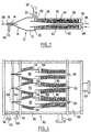
- Figure 4 is a schematic cross-sectional view of a set of separators according to another variant of the invention.
- Figure 1 is a cross-sectional view of a three-phase cyclone separator which includes a body 10 consisting of a cylindrical part 12 and a part conical 14.
- the conical part 14 is provided, at the top of the cone, of a final cylindrical section 16 inside which is arranged a tubular outlet 18, both being located coaxially with the cylindrical part 12.
- the body 10 is closed by an annular element 20 which includes one or more entry (s) 22 for the emulsion to be treated in the cyclone.
- the entrance is arranged tangentially with respect to the cylindrical part 12.
- a generally tubular element 26 which includes a portion of low taper 28 and a cylindrical extension 30.
- An oil / water emulsion containing a solid material suspended enters the body under pressure through entrance 22 in the direction of arrow 32 and take thus a tangential path to the body 10.
- the emulsion flows at high speed in a roundabout movement inside the cylindrical part 12.
- the solid matter in suspension migrates to the walls of the cylindrical part 12 and the conical part 14 and is discharged through the final section 16, in the direction of arrow 34.
- the conical configuration of part 14 strength the oil / water emulsion, from which the solid material was withdrawn, to change its longitudinal direction of flow and to pass through the tubular element 26 while continuing to flow in its gyratory movement.
- the two phases of the emulsion separate during its passage along the portion of weak conicity 28, the water located towards the wall of parts 28 and 30, while the oil moves towards the axis thereof.
- Back pressure caused by a restriction formed to the end of the tubular extension 30 applies to the oil flow and causes it to reverse its direction.
- An oil stream is therefore formed to flow in a direction opposite to that of water, and the oil leaves the separator through the exit 18 in the direction of arrow 36, the water purified leaving tubular extension 30 in the arrow direction 38.
- a coalescer that is to say coalescing means 40, is arranged around and mounted directly on the tubular member 20, substantially the along the entire length of it.
- the coalescer is of the brush type and is composed a large number of hairs, made of oleophilic matter, which generally project radially from the outer wall of the tubular element 20.
- the oleophilic material used is a material plastic such as polyamide or polypropylene.
- a cylindrical sleeve 42 is located around the coalescer and defines with the annular element 20 a chamber of coalescence 44.
- the cylindrical extension 30 projects through an end wall 46 of the cylindrical sleeve 42.
- the cylindrical sleeve 42 includes an inlet 48 and an output 50 which communicates directly with input 22 of the cyclone separator.
- the cylindrical sleeve can be formed by the walls of the container containing the cyclone separator.
- the emulsion to be treated When running, the emulsion to be treated is injected into entrance 48 of coalescence chamber 44 where it progresses along the length of the tubular member 26, touching the oleophilic brushes of the coalescer 40, before leaving the room via exit 50.
- the contact between the emulsion and the oleophilic brushes causes microscopic oil droplets in the emulsion to coalesce and form droplets of which the average diameter has been considerably increased. These droplets remain in suspension in the emulsion when it leaves the coalescing chamber 44 through the exit 50.
- the pretreated emulsion containing the droplets of magnified oil, is then injected into the separator cyclone through entrance 22 where it follows the path described above.
- the diameter mean oil droplets is significantly more large than in an untreated emulsion, the yield of cyclone is significantly increased, the percentage of oil removed from the emulsion being increased by approximately 5 to 20% depending on the characteristics of the emulsion that comes in.
- FIG. 2 A second variant has been shown in Figure 2 a cyclone separator according to the first aspec of the invention in which, for the sake of ease of manufacture and maintenance, the coalescer is constituted as a separate subset which can be mounted on an existing cyclone.
- a cyclone separator 60 which in the example illustrated is a two-phase cyclone, has a set of coalescers, that is to say coalescing means 64, arranged around the tubular element 62, which includes a generally tubular sleeve 66 of which the internal dimensions correspond exactly to external dimensions of the tubular element 62 and of the conical part 68, the coalescing means being mounted on the sleeve.
- the tubular sleeve 66 is more clearly visible in Figure 2a.
- the functioning cyclone and the upstream pretreatment stage constituted by the coalescer is similar to that of the variant of Figure 1.
- FIG. 3 and 3a another variant of cyclone which differs from that of Figures 2 and 2a in that the tubular sleeve on which the brush coalescer has a cross section constant cylindrical.
- a tubular sleeve 70 of cross section constant, is mounted on the cyclone separator 72 between the conical part 74 and an injector 76 at the end of the tubular element 78.
- the functioning of the cyclone and upstream pretreatment coalescer is similar to that of the variants of Figures 1 and 2, the element tubular and coalescer being inserted into a sleeve tubular (not shown), as in the case of the device of Figure 1.
- Figure 4 shows a variant according to the second aspect of the invention which differs from those described previously in what several cyclone separators, with their associated coalescers, are arranged in a room common containing the emulsion to be treated.
- a set separators is divided into rooms 82, 84, 86, 88, each separate from the adjoining room by a partition wall.
- the main or supply chamber 82 contains several cyclone separators, three in the example illustrated, arranged side by side.
- brush coalescers 96 are mounted on the surface outside of the tubular part 92 of each separator 90, and on the outer surface of the body 94 of each separator.
- coalescers i.e. the coalescing means 96, can be either directly mounted on cyclone separators, either can be mounted on tubular sleeves as shown.
- the supply chamber 82 includes an inlet 100 for the emulsion to be treated.
- the emulsion enters the room 82, passes over and through the coalescers at brush, and enters the inputs 102 of the separators to cyclone 90.
- the sand passes outlets 104 into the sand chamber 84 that he leaves by exit 106; the oil leaves the separators 90 through the outputs 108 which open into the oil chamber 86 which it leaves via outlet 110; and clean water leaves the tubular parts 92 and passes in the clean water chamber which it leaves through the outlet 112.
Abstract
Description
La présente invention est relative à un séparateur à cyclone ayant un coalesceur incorporé et, plus particulièrement, à un tel séparateur ayant un coalesceur qui est apte à constituer pour celui-ci un stade de prétraitement en amont, ainsi qu'à un ensemble comprenant une plurialité de tels séparateurs.The present invention relates to a separator with cyclone having an incorporated coalescer and, more particularly, to such a separator having a coalescer which is capable of constituting for it a stage of upstream pretreatment, as well as a set comprising a plurality of such separators.
Des séparateurs à cyclone, plus communément appelés des hydrocyclones, sont généralement destinés à séparer deux phases immiscibles de densités différentes. Dans ce type de séparateur, le mélange des deux phases à séparer est injecté à grande vitesse dans une chambre qui est généralement cylindrique de telle façon que le mélange progresse à travers la chambre avec un mouvement giratoire. Les forces centrifuges générées par ce mouvement giratoire agissant sur le mélange des deux phases de densités différentes provoquent la migration de la phase plus dense vers la paroi de la chambre, la phase plus légère restant vers l'intérieur de la chambre. En disposant deux sorties axiales pour les phases, une vers la paroi de la chambre et l'autre le long de l'axe de la chambre, et en utilisant un arrangement de contre-pression, les deux phases peuvent être séparées. Ce principe de fonctionnement est particulièrement adapté pour séparer une émulsion huile/eau en ses deux composants. La sortie axiale de ce type de séparateur comprend généralement une partie tubulaire de faible conicité qui est raccordée à la chambre cylindrique par une partie conique. Un séparateur à cyclone à deux phases de ce type est décrit dans US-A-4.749.490.Cyclone separators, more commonly known hydrocyclones, are generally intended to separate two immiscible phases of different densities. In this type of separator, the mixture of the two phases to be separated is injected at high speed into a chamber which is generally cylindrical in such a way that the mixture progresses through the room with movement roundabout. The centrifugal forces generated by this gyratory movement acting on the mixture of the two phases of different densities cause the migration of the denser phase towards the wall of the chamber, the phase lighter remaining towards the interior of the chamber. In having two axial outputs for the phases, one towards the wall of the chamber and the other along the axis of the chamber, and using a back pressure arrangement, the two phases can be separated. This operating principle is particularly suitable to separate an oil / water emulsion into its two components. The axial outlet of this type of separator generally includes a tubular portion of low taper which is connected to the cylindrical chamber by a conical part. Two cyclone separator phases of this type are described in US-A-4,749,490.
Des séparateurs à cyclone à trois phases aptes à séparer une phase solide, par exemple du sable, qui est en suspension dans une émulsion composée, par exemple, d'huile et d'eau, sont également connus. Un tel séparateur à trois phases est décrit dans US-A-5.332.500. Les cyclones à trois phases ont en commun avec les séparateurs à deux phases une sortie pour une des phases liquides qui comprend une partie tubulaire allongée de faible conicité.Three-phase cyclone separators suitable for separate a solid phase, for example from sand, which is suspended in a compound emulsion, for example, oil and water are also known. Such three-phase separator is described in US-A-5,332,500. Three-phase cyclones have in common with two-phase separators one output for one of the phases liquids which includes an elongated tubular part of weak taper.
Une application principale des séparateurs à cyclone est le traitement des eaux usées issues de puits de production de pétrole et/ou de gaz. Typiquement, les séparateurs à cyclone sont utilisés sur des plates-formes maritimes de production de pétrole pour traiter le mélange huile/eau/sable qui est séparé des fluides de production dans le but de nettoyer l'eau avant son évacuation ou sa réinjection. L'espace disponible sur une plate-forme de production est très limité. Plusieurs séparateurs à cyclone sont généralement installés côte à côte dans une unité de traitement située sur la plate-forme. Cependant, la forme des parties coniques décrites antérieurement, et celle des parties tubulaires de faible conicité, signifient qu'il y a une quantité considérable d'espace perdu dans l'unité de traitement entre les différents séparateurs. En outre, il est souhaitable, dans le but d'augmenter le rendement du séparateur, de prévoir un stade de prétraitement, en amont du séparateur, pour le mélange à traiter. Dans le cas d'une émulsion huile/eau, ce stade de prétraitement comprend avantageusement un coalesceur destiné à transformer les gouttes microscopiques d'huile dans l'émulsion en gouttes plus grosses qui sont séparées plus facilement dans le cyclone. Cependant, dans le cas où l'unité de traitement doit être installée sur une plate-forme de production, de tels coalesceurs ne peuvent pas être utilisés à cause du manque d'espace disponible.A main application of cyclone separators is the treatment of wastewater from wells oil and / or gas production. Typically, cyclone separators are used on platforms oil production maritime to process the oil / water / sand mixture which is separated from the production in order to clean the water before its evacuation or reinjection. The space available on a production platform is very limited. Many cyclone separators are generally installed next to side in a processing unit located on the platform. However, the shape of the conical parts described previously, and that of the tubular parts of weak taper, mean that there is a considerable amount of space lost in the processing unit between different separators. In addition, it is desirable, in order to increase the efficiency of the separator, provide a pretreatment stage, upstream of the separator, for the mixture to be treated. In the case of a oil / water emulsion, this pretreatment stage includes advantageously a coalescer intended to transform the microscopic drops of oil in the emulsion in drops larger which are more easily separated in the cyclone. However, in the event that the processing unit must be installed on a production platform, such coalescers cannot be used due to the lack of available space.
Le document US-A-4 116 790 divulgue des séparateurs à cyclone comprenant en outre des coalesceurs électrostatiques. Les électrodes peuvent être arrangées sur l'entrée tangentielle (Figs. 1-3) ou bien autour du cyclone entier (Figs. 4a, 4b). La paroi d'une chambre cylindrique entourant le cyclone, la partie conique du cyclone, ainsi qu'un élément conique entourant la tubulaire de sortie peuvent constituer des électrodes.US-A-4,116,790 discloses cyclone separators further comprising electrostatic coalescers. The electrodes can be arranged on the tangential entry (Figs. 1-3) or else around the entire cyclone (Figs. 4a, 4b). The wall of a cylindrical chamber surrounding the cyclone, the part conical cyclone, as well as a conical element surrounding the outlet tubular can constitute electrodes.
L'objet de la présente invention est par conséquent de proposer un séparateur à cyclone ayant un coalesceur en amont pour prétraiter l'émulsion à séparer, mais qui est plus compact que les dispositifs proposés précédemment et réduit donc l'espace perdu, ainsi qu'un ensemble comprenant une pluralité de tels séparateurs.The object of the present invention is therefore to propose a cyclone separator having a coalescer upstream to pre-treat the emulsion to be separated, but which is more compact than the proposed devices previously and therefore reduces the space lost, as well as an assembly comprising a plurality of such separators.
Suivant un premier aspect de l'invention, il est proposé un séparateur à cyclone tel que défini dans la revendication 1, des modes particuliers étant définis dans les revendications 2-4. According to a first aspect of the invention, a separator is proposed. cyclone as defined in claim 1, particular modes being defined in claims 2-4.
Selon un deuxième aspect de l'invention, il est proposé un ensemble de séparateurs, comprenant une pluralité de séparateurs à cyclone, tel que défini dans la revendication 5,des models particuliers étant l'objet des revendications 6-10.According to a second aspect of the invention, a set of separators is proposed, comprising a plurality of cyclone separators, as defined in claim 5, particular models being the subject of claims 6-10.
La présente invention va maintenant être décrite à titre d'exemple seulement, en se référant aux dessins annexés, dans lesquels laThe present invention will now be described in as an example only, referring to the drawings annexed, in which the
Figure 1 est une vue schématique en section transversale d'un séparateur à cyclone ayant un coalesceur incorporé, suivant une première variante de l'invention; lesFigure 1 is a schematic cross-sectional view a cyclone separator having a coalescer incorporated, according to a first variant of the invention; the
Figures 2 et 3 sont des vues schématiques en section transversale de séparateurs suivant une deuxième et une troisième variantes de l'invention; lesFigures 2 and 3 are schematic sectional views transverse of separators according to a second and a third variants of the invention; the
Figures 2a et 3a sont des vues détaillées de parties des séparateurs des Figures 2 et 3 respectivement; et laFigures 2a and 3a are detailed views of parts separators of Figures 2 and 3 respectively; and the
Figure 4 est une vue schématique en section transversale d'un ensemble de séparateurs suivant une autre variante de l'invention.Figure 4 is a schematic cross-sectional view of a set of separators according to another variant of the invention.
La Figure 1 est une vue en coupe transversale d'un
séparateur à cyclone à trois phases qui comprend un corps
10 constitué d'une partie cylindrique 12 et d'une partie
conique 14. La partie conique 14 est pourvue, au sommet
du cône, d'un tronçon final cylindrique 16 à l'intérieur
duquel est disposée une sortie tubulaire 18, les deux
étant situés coaxialement à la partie cylindrique 12.Figure 1 is a cross-sectional view of a
three-phase cyclone separator which includes a
Le corps 10 est fermé par un élément annulaire 20
qui comprend une ou plusieurs entrée (s) 22 pour
l'émulsion à traiter dans le cyclone. L'entrée est
disposée tangentiellement par rapport à la partie cylindrique
12. Dans l'ouverture de l'élément annulaire est
monté de façon étanche un élément généralement tubulaire
26 qui comprend une partie de faible conicité 28 et une
extension cylindrique 30.The
Une émulsion huile/eau contenant une matière solide
en suspension entre dans le corps sous pression à travers
l'entrée 22 dans la direction de la flèche 32 et emprunte
ainsi un chemin tangentiel au corps 10. L'émulsion
s'écoule à grande vitesse en un mouvement giratoire à
l'intérieur de la partie cylindrique 12. Sous l'effet de
la force centrifuge ainsi générée, la matière solide en
suspension migre vers les parois de la partie cylindrique
12 et de la partie conique 14 et est évacuée à travers le
tronçon final 16, dans la direction de la flèche 34.An oil / water emulsion containing a solid material
suspended enters the body under pressure through
La configuration conique de la partie 14 force
l'émulsion huile/eau, de laquelle la matière solide a été
retirée, à changer sa direction longitudinale d'écoulement
et à passer dans l'élément tubulaire 26 tout en
continuant à s'écouler dans son mouvement giratoire. Les
deux phases de l'émulsion se séparent pendant son passage
le long de la partie de faible conicité 28, l'eau se
trouvant vers la paroi des parties 28 et 30, tandis que
l'huile se déplace vers l'axe de celle-ci. Une contre-pression
provoquée par une restriction formée à
l'extrémité de l'extension tubulaire 30 (non montrée)
s'applique à l'écoulement d'huile et l'entraíne à
inverser sa direction. Un courant d'huile est donc formé
pour s'écouler dans une direction opposée à celle de
l'eau, et l'huile quitte le séparateur à travers la
sortie 18 dans la direction de la flèche 36, l'eau
purifiée quittant l'extension tubulaire 30 dans la
direction de la flèche 38.The conical configuration of
Suivant le premier aspect de l'invention, un coalesceur, c'est à dire des moyens de coalescence 40, est disposé
autour de et monté directement sur l'élément tubulaire 20, substantiellement le
long de toute la longueur de celui-ci. Dans l'exemple
montré, le coalesceur est du type à brosse et est composé
d'un grand nombre de poils, faits de matière oléophile,
qui se projettent généralement radialement à partir de la
paroi extérieure de l'élément tubulaire 20. De
préférence, la matière oléophile utilisée est une matière
plastique telle que du polyamide ou du polypropylène. Un
manchon cylindrique 42 est situé autour du coalesceur et
définit avec l'élément annulaire 20 une chambre de
coalescence 44. L'extension cylindrique 30 se projette
à travers une paroi d'extrémité 46 du manchon cylindrique
42. Le manchon cylindrique 42 comprend une entrée 48 et
une sortie 50 qui communique directement avec l'entrée 22
du séparateur à cyclone. Le manchon cylindrique peut
être formé par les parois du récipient contenant le
séparateur à cyclone.According to the first aspect of the invention, a coalescer, that is to say coalescing
En marche, l'émulsion à traiter est injectée dans
l'entrée 48 de la chambre de coalescence 44 où elle
progresse le long de la longueur de l'élément tubulaire
26, touchant les brosses oléophiles du coalesceur 40,
avant de sortir de la chambre par la sortie 50. Pendant
son passage à travers la chambre de coalescence 44, le
contact entre l'émulsion et les brosses oléophiles
entraíne les gouttelettes microscopiques d'huile dans
l'émulsion à coalescer et à former des gouttelettes dont
le diamètre moyen a été considérablement augmenté. Ces
gouttelettes restent en suspension dans l'émulsion
lorsqu'elle quitte la chambre de coalescence 44 par la
sortie 50.When running, the emulsion to be treated is injected into
L'émulsion prétraitée, contenant les gouttelettes
d'huile grossies, est alors injectée dans le séparateur
à cyclone à travers l'entrée 22 où elle suit le chemin
décrit ci-dessus. Cependant, tandis que le diamètre
moyen des gouttelettes d'huile est significativement plus
grand que dans une émulsion non traitée, le rendement du
cyclone est considérablement augmenté, le pourcentage
d'huile retiré de l'émulsion étant augmenté d'approximativement
5 à 20 % en fonction des caractéristiques de
l'émulsion qui entre.The pretreated emulsion, containing the droplets
of magnified oil, is then injected into the separator
cyclone through
On a montré dans la Figure 2 une deuxième variante
d'un séparateur à cyclone selon le premier aspec de l'invention dans lequel, dans un souci de
facilité de fabrication et d'entretien, le coalesceur est
constitué comme un sous-ensemble séparé qui peut être
monté sur un cyclone existant. Dans la variante
présentée, un séparateur à cyclone 60, qui dans l'exemple
illustré est un cyclone à deux phases, a un ensemble de
coalesceurs, c'est à dire de moyens de coalescence 64, disposé autour de l'élément tubulaire 62,
qui comprend un manchon généralement tubulaire 66 dont
les dimensions internes correspondent exactement aux
dimensions extérieures de l'élément tubulaire 62 et de la
partie conique 68, les moyens coalescents étant montés sur le manchon. Le manchon tubulaire 66 est plus
clairement visible dans la Figure 2a. Le fonctionnement
du cyclone et du stade de prétraitement en amont
constitué par le coalesceur est similaire à celui de la
variante de la Figure 1.A second variant has been shown in Figure 2
a cyclone separator according to the first aspec of the invention in which, for the sake of
ease of manufacture and maintenance, the coalescer is
constituted as a separate subset which can be
mounted on an existing cyclone. In the variant
shown, a
On a montré dans les Figures 3 et 3a une autre
variante de cyclone qui diffère de celle des Figures 2 et
2a en ce que le manchon tubulaire sur lequel est monté le
coalesceur à brosse a une section transversale
cylindrique constante. Comme cela est montré dans les
figures, un manchon tubulaire 70, de section transversale
constante, est monté sur le séparateur à cyclone 72 entre
la partie conique 74 et un injecteur 76 à l'extrémité de
l'élément tubulaire 78. Le fonctionnement du cyclone et
du coalesceur de prétraitement en amont est similaire à
celui des variantes des Figures 1 et 2, l'élément
tubulaire et le coalesceur étant insérés dans un manchon
tubulaire (non montré), comme dans le cas du dispositif
de la Figure 1.We have shown in Figures 3 and 3a another
variant of cyclone which differs from that of Figures 2 and
2a in that the tubular sleeve on which the
brush coalescer has a cross section
constant cylindrical. As shown in
figures, a
La Figure 4 montre une variante selon le second aspect de l'invention qui diffère de celles décrites précédemment en ce que plusieurs séparateurs à cyclone, avec leurs coalesceurs associés, sont disposés dans une chambre commune contenant l'émulsion à traiter.Figure 4 shows a variant according to the second aspect of the invention which differs from those described previously in what several cyclone separators, with their associated coalescers, are arranged in a room common containing the emulsion to be treated.
Comme cela est montré dans la Figure 4, un ensemble
de séparateurs, désigné d'une manière générale par 80,
est divisé en chambres 82, 84, 86, 88, chacune séparée de
la chambre voisine par une paroi de séparation. La
chambre principale ou d'alimentation 82 contient
plusieurs séparateurs à cyclone, trois dans l'exemple
illustré, disposés côte à côte. Sur la surface
extérieure de la partie tubulaire 92 de chaque séparateur
90, et sur la surface extérieure du corps 94 de chaque
séparateur, sont montés des coalesceurs à brosse 96. Les
coalesceurs, c'est à dire les moyens de coalescence 96, peuvent être soit directement montés sur
les séparateurs à cyclone, soit peuvent être montés sur
des manchons tubulaires comme cela est montré.As shown in Figure 4, a set
separators, generally designated by 80,
is divided into
La chambre d'alimentation 82 comprend une entrée 100
pour l'émulsion à traiter. L'émulsion entre dans la
chambre 82, passe sur et à travers les coalesceurs à
brosse, et entre dans les entrées 102 des séparateurs à
cyclone 90. Après le traitement dans les séparateurs 90,
le sable passe des sorties 104 dans la chambre à sable 84
qu'il quitte par la sortie 106; l'huile quitte les
séparateurs 90 par les sorties 108 qui s'ouvrent dans la
chambre à huile 86 qu'elle quitte par la sortie 110; et
l'eau propre quitte les parties tubulaires 92 et passe
dans la chambre à eau propre qu'elle quitte par la sortie
112.The
Pendant son passage à travers la chambre
d'alimentation 82, l'émulsion, qui se déplace relativement
lentement, entre en contact avec un grand nombre de
poils des coalesceurs à brosse 96 entraínant les
gouttelettes d'huile contenues dans l'émulsion à
coalescer et à former de plus grosses gouttelettes dont
le diamètre moyen est significativement plus grand.While passing through the
Chacune des variantes de la présente invention décrite ci-dessus, en assurant que l'huile dans l'émulsion à traiter est au moins partiellement séparée de l'émulsion, et comprend des gouttelettes ayant un plus grand diamètre moyen, avant son entrée dans le cyclone, améliore considérablement le rendement du séparateur à cyclone tout en n'augmentant pas le volume total de l'unité de séparateur.Each of the variants of the present invention described above, ensuring that the oil in the emulsion to be treated is at least partially separated of the emulsion, and includes droplets having a higher large average diameter, before entering the cyclone, considerably improves the efficiency of the separator cyclone while not increasing the total volume of the separator unit.
Claims (10)
- A cyclone separator comprising a body (10), formed of a cylindrical portion (12) and a substantially conical convergent portion (14), at least one inlet (22) mounted tangentially on the cylindrical portion (12) and a substantially tubular element (26; 62; 78) coaxial to the cylindrical portion (12) of the body and mounted on the body and in hydraulic communication therewith, the separator also comprising coalescence means (40; 64) disposed around the tubular element and suitable for receiving liquid to be separated before its entry into the cyclone, the said coalescence means being directly mounted on the tubular element, or on a tubular sleeve (66; 70) mounted on the tubular element.
- A cyclone separator according to Claim 1,
characterised in that the said coalescence means are of the brush type. - A cyclone separator according to Claim 2,
characterised in that the said coalescence means comprise a plurality of hairs made from oil-absorbing material. - A cyclone separator according to any one of the preceding Claims,
characterised in that it also comprises coalescence means disposed around its body (10). - An assembly of separators comprising a plurality of cyclone separators, each of the said cyclone separators comprising a body (94) formed from a cylindrical portion and a substantially conical convergent portion, at least one inlet (102) mounted tangentially on the cylindrical portion and a substantially tubular element (92) coaxial to the cylindrical portion of the body and mounted on the body and in hydraulic communication therewith, each of the said cyclone separators also comprising coalescence means (96) disposed around the tubular element and suitable for receiving liquid to be separated before its entry into the cyclone, the said separators being disposed in a common chamber (82), suitable for receiving an emulsion to be treated, which directly communicates with the inlets (102) of the separators.
- An assembly of separators according to Claim 5,
characterised in that the coalescence means are of the brush type. - An assembly of separators according to Claim 6,
characterised in that the coalescence means comprise a plurality of hairs made from oil-absorbing material. - An assembly of separators according to Claim 5, 6, or 7,
characterise in that the coalescence means are mounted directly on the tubular elements. - An assembly of separators according to Claim 5, 6 or 7,
characterised in that the coalescence means each comprise a tubular sleeve mounted on the tubular element. - An assembly of separators according to any one of Claims 5-9,
characterised in that the said cyclone separators each also comprise coalescence means disposed around their body (94).
Applications Claiming Priority (2)
| Application Number | Priority Date | Filing Date | Title |
|---|---|---|---|
| FR9503825 | 1995-03-31 | ||
| FR9503825A FR2732234B1 (en) | 1995-03-31 | 1995-03-31 | CYCLONE SEPARATOR HAVING INCORPORATED COALESCER |
Publications (2)
| Publication Number | Publication Date |
|---|---|
| EP0734751A1 EP0734751A1 (en) | 1996-10-02 |
| EP0734751B1 true EP0734751B1 (en) | 2001-08-22 |
Family
ID=9477627
Family Applications (1)
| Application Number | Title | Priority Date | Filing Date |
|---|---|---|---|
| EP96400638A Expired - Lifetime EP0734751B1 (en) | 1995-03-31 | 1996-03-26 | Cyclone separator with coalescence element |
Country Status (10)
| Country | Link |
|---|---|
| US (1) | US5616244A (en) |
| EP (1) | EP0734751B1 (en) |
| AT (1) | ATE204502T1 (en) |
| CA (1) | CA2173087C (en) |
| DE (1) | DE69614595T2 (en) |
| DK (1) | DK0734751T3 (en) |
| ES (1) | ES2162988T3 (en) |
| FR (1) | FR2732234B1 (en) |
| NO (1) | NO308833B1 (en) |
| PT (1) | PT734751E (en) |
Families Citing this family (23)
| Publication number | Priority date | Publication date | Assignee | Title |
|---|---|---|---|---|
| GB9813864D0 (en) * | 1998-06-27 | 1998-08-26 | Ert Limited | Two phase liquid media coalescer |
| GB9902220D0 (en) * | 1999-02-01 | 1999-03-24 | Cyclotech Limited | Fluid processing |
| US6730236B2 (en) | 2001-11-08 | 2004-05-04 | Chevron U.S.A. Inc. | Method for separating liquids in a separation system having a flow coalescing apparatus and separation apparatus |
| US7736501B2 (en) | 2002-09-19 | 2010-06-15 | Suncor Energy Inc. | System and process for concentrating hydrocarbons in a bitumen feed |
| CA2471048C (en) | 2002-09-19 | 2006-04-25 | Suncor Energy Inc. | Bituminous froth hydrocarbon cyclone |
| DE102006022156A1 (en) * | 2006-05-12 | 2007-11-29 | Westfalia Separator Ag | Method and device for the treatment of liquids |
| GB0624936D0 (en) * | 2006-12-14 | 2007-01-24 | Aker Kvaerner Process Systems | Fluid treatment |
| PL2176002T3 (en) * | 2007-07-30 | 2014-11-28 | Merpro Tortek Ltd | Cyclone apparatus |
| NL2000827C2 (en) * | 2007-08-22 | 2009-02-24 | Schinfa Engineering | Hydrocyclone separator, has mixture delivered to separation region via elongated symmetrical coalescence chamber |
| GB2457012B (en) * | 2008-01-22 | 2012-09-12 | Caltec Ltd | Separation system and method |
| CN102164644B (en) * | 2008-09-03 | 2014-05-07 | 康明斯过滤Ip公司 | Air-jacketed coalescer media with improved performance |
| US8590712B2 (en) * | 2008-10-08 | 2013-11-26 | Cummins Filtration Ip Inc. | Modular filter elements for use in a filter-in-filter cartridge |
| US8360251B2 (en) | 2008-10-08 | 2013-01-29 | Cummins Filtration Ip, Inc. | Multi-layer coalescing media having a high porosity interior layer and uses thereof |
| US8517185B2 (en) * | 2008-10-08 | 2013-08-27 | Cummins Filtration Ip, Inc. | Two stage fuel water separator and particulate filter utilizing pleated nanofiber filter material |
| CN102596862B (en) | 2009-05-15 | 2015-09-30 | 康明斯过滤Ip公司 | Surface coalescer |
| CA2689021C (en) | 2009-12-23 | 2015-03-03 | Thomas Charles Hann | Apparatus and method for regulating flow through a pumpbox |
| US8932472B2 (en) | 2011-10-25 | 2015-01-13 | National Oilwell Varco, L.P. | Separator system and related methods |
| US10058808B2 (en) | 2012-10-22 | 2018-08-28 | Cummins Filtration Ip, Inc. | Composite filter media utilizing bicomponent fibers |
| GB2517985B (en) * | 2013-09-09 | 2016-01-06 | Berishtenu Agricultural Cooperative | Sheaf-based fluid filter |
| CN105688449B (en) * | 2016-03-05 | 2017-07-14 | 东北石油大学 | A kind of internal cone type variable cross-section spiral oil water separator |
| CN105772238B (en) * | 2016-05-17 | 2018-04-06 | 东北石油大学 | compact gas-liquid-solid three-phase separator |
| DE112017002974T5 (en) | 2016-07-19 | 2019-03-07 | Cummins Filtration Ip, Inc. | KOALESZER WITH PERFORATED LAYER |
| US11731885B2 (en) | 2020-03-17 | 2023-08-22 | Fluid Handling Llc | Coalescing media for hydronic air and sediment separation device |
Family Cites Families (6)
| Publication number | Priority date | Publication date | Assignee | Title |
|---|---|---|---|---|
| US3794583A (en) * | 1972-08-28 | 1974-02-26 | Oil Mop International Inc | Method and apparatus for separating oil from an oil water mixture |
| US4116790A (en) * | 1977-07-18 | 1978-09-26 | Combustion Engineering, Inc. | Method and apparatus for separation of fluids with an electric field and centrifuge |
| GB8417783D0 (en) * | 1984-07-12 | 1984-08-15 | Shell Int Research | Treating liquids |
| WO1988009698A1 (en) * | 1987-06-10 | 1988-12-15 | Conoco Specialty Products Inc. | Liquid separator |
| GB9116020D0 (en) * | 1991-07-25 | 1991-09-11 | Serck Baker Ltd | Separator |
| FR2690089B1 (en) * | 1992-04-15 | 1994-10-21 | Elf Aquitaine | Three-phase cyclone separator. |
-
1995
- 1995-03-31 FR FR9503825A patent/FR2732234B1/en not_active Expired - Lifetime
-
1996
- 1996-03-18 US US08/617,444 patent/US5616244A/en not_active Expired - Lifetime
- 1996-03-26 DK DK96400638T patent/DK0734751T3/en active
- 1996-03-26 AT AT96400638T patent/ATE204502T1/en active
- 1996-03-26 DE DE69614595T patent/DE69614595T2/en not_active Expired - Lifetime
- 1996-03-26 EP EP96400638A patent/EP0734751B1/en not_active Expired - Lifetime
- 1996-03-26 ES ES96400638T patent/ES2162988T3/en not_active Expired - Lifetime
- 1996-03-26 PT PT96400638T patent/PT734751E/en unknown
- 1996-03-29 CA CA002173087A patent/CA2173087C/en not_active Expired - Fee Related
- 1996-04-01 NO NO961323A patent/NO308833B1/en not_active IP Right Cessation
Also Published As
| Publication number | Publication date |
|---|---|
| EP0734751A1 (en) | 1996-10-02 |
| AU690821B2 (en) | 1998-04-30 |
| NO961323L (en) | 1996-10-01 |
| NO961323D0 (en) | 1996-04-01 |
| FR2732234B1 (en) | 1997-05-23 |
| DE69614595D1 (en) | 2001-09-27 |
| DE69614595T2 (en) | 2002-06-27 |
| DK0734751T3 (en) | 2001-12-10 |
| US5616244A (en) | 1997-04-01 |
| ES2162988T3 (en) | 2002-01-16 |
| NO308833B1 (en) | 2000-11-06 |
| ATE204502T1 (en) | 2001-09-15 |
| PT734751E (en) | 2002-02-28 |
| FR2732234A1 (en) | 1996-10-04 |
| CA2173087C (en) | 2005-06-14 |
| AU4815896A (en) | 1996-10-10 |
| CA2173087A1 (en) | 1996-10-01 |
Similar Documents
| Publication | Publication Date | Title |
|---|---|---|
| EP0734751B1 (en) | Cyclone separator with coalescence element | |
| EP0228097B1 (en) | Rotating vortex separator for a heterogeneous liquid | |
| CA2637643C (en) | Cyclone separator | |
| CA2310139C (en) | Device and method for separating a heterogeneous mixture | |
| FR2632216A1 (en) | SEPARATION DEVICE WITH SWIRL TUBE | |
| FR2632215A1 (en) | SEPARATION DEVICE WITH SWIRL TUBE | |
| EP0617115A1 (en) | Device and process for separating phases of different densities and conductivities by electrocoalescense and centrifugation | |
| FI58954B (en) | HYDROCYKLON | |
| EP0145552A2 (en) | Filter with two distinct filtering stacks | |
| EP0566432B1 (en) | Three-phase cyclone separator | |
| WO2000029335A1 (en) | Water treatment method by ballasted floc including a recycling of granular material | |
| WO2009147336A2 (en) | Oil separator for internal combustion engine | |
| FR2478489A1 (en) | METHOD AND DEVICE FOR SEPARATING PARTICLES IN A FLUID, IN PARTICULAR FOR PURIFYING PAPER SUSPENSIONS | |
| EP0401276A1 (en) | Separating liquids | |
| FR2464100A1 (en) | CENTRIFUGAL SEPARATOR WITH OVERFLOW DEVICE | |
| FR2460701A1 (en) | DEVICE FOR SEPARATING SOLID MATERIALS IN A LIQUID CURRENT | |
| FR2841485A1 (en) | ANNULAR CENTRIFUGAL EXTRACTOR WITH NOYE AGITATION ROTOR | |
| BE1000524A4 (en) | Method and device for aerodynamic separation of components of a gas flow. | |
| FR2476504A1 (en) | SEPARATOR FOR THE SEPARATION OF A SUSPENSION MIXTURE AND HEAVY AND COARSE PARTICLES | |
| WO1999032210A1 (en) | Assembly for automatic purification of a polluted fluid and implementing method | |
| WO2011073550A1 (en) | Cyclonic flow separator | |
| FR2726203A1 (en) | Treatment of aqueous effluents in a centripetal flotation separator | |
| US9073064B2 (en) | Cyclonic separation system comprising gas injection means and method for separating a fluid mixture | |
| FR2588779A1 (en) | Vortex separator for a heterogeneous liquid having a variable flow rate | |
| FR2556778A1 (en) | GAS-LIQUID SEPARATION DEVICE AND ITS APPLICATION TO DECOILING THE VENTILATION AIR OF THE BEARING SPEAKERS OF A TURBOMACHINE |
Legal Events
| Date | Code | Title | Description |
|---|---|---|---|
| PUAI | Public reference made under article 153(3) epc to a published international application that has entered the european phase |
Free format text: ORIGINAL CODE: 0009012 |
|
| 17P | Request for examination filed |
Effective date: 19960330 |
|
| AK | Designated contracting states |
Kind code of ref document: A1 Designated state(s): AT BE CH DE DK ES FR GB GR IE IT LI LU NL PT SE |
|
| RAP1 | Party data changed (applicant data changed or rights of an application transferred) |
Owner name: ELF EXPLORATION PRODUCTION |
|
| 17Q | First examination report despatched |
Effective date: 19991108 |
|
| RAP1 | Party data changed (applicant data changed or rights of an application transferred) |
Owner name: CYCLOTECH LTD. |
|
| GRAG | Despatch of communication of intention to grant |
Free format text: ORIGINAL CODE: EPIDOS AGRA |
|
| GRAG | Despatch of communication of intention to grant |
Free format text: ORIGINAL CODE: EPIDOS AGRA |
|
| GRAH | Despatch of communication of intention to grant a patent |
Free format text: ORIGINAL CODE: EPIDOS IGRA |
|
| GRAH | Despatch of communication of intention to grant a patent |
Free format text: ORIGINAL CODE: EPIDOS IGRA |
|
| GRAA | (expected) grant |
Free format text: ORIGINAL CODE: 0009210 |
|
| AK | Designated contracting states |
Kind code of ref document: B1 Designated state(s): AT BE CH DE DK ES FR GB GR IE IT LI LU NL PT SE |
|
| REF | Corresponds to: |
Ref document number: 204502 Country of ref document: AT Date of ref document: 20010915 Kind code of ref document: T |
|
| REG | Reference to a national code |
Ref country code: CH Ref legal event code: EP |
|
| REF | Corresponds to: |
Ref document number: 69614595 Country of ref document: DE Date of ref document: 20010927 |
|
| REG | Reference to a national code |
Ref country code: IE Ref legal event code: FG4D Free format text: FRENCH |
|
| REG | Reference to a national code |
Ref country code: DK Ref legal event code: T3 |
|
| GBT | Gb: translation of ep patent filed (gb section 77(6)(a)/1977) |
Effective date: 20011117 |
|
| REG | Reference to a national code |
Ref country code: GB Ref legal event code: IF02 |
|
| REG | Reference to a national code |
Ref country code: ES Ref legal event code: FG2A Ref document number: 2162988 Country of ref document: ES Kind code of ref document: T3 |
|
| REG | Reference to a national code |
Ref country code: PT Ref legal event code: SC4A Free format text: AVAILABILITY OF NATIONAL TRANSLATION Effective date: 20011115 Ref country code: GR Ref legal event code: EP Ref document number: 20010402125 Country of ref document: GR |
|
| PGFP | Annual fee paid to national office [announced via postgrant information from national office to epo] |
Ref country code: IE Payment date: 20020327 Year of fee payment: 7 |
|
| PG25 | Lapsed in a contracting state [announced via postgrant information from national office to epo] |
Ref country code: IE Free format text: LAPSE BECAUSE OF FAILURE TO SUBMIT A TRANSLATION OF THE DESCRIPTION OR TO PAY THE FEE WITHIN THE PRESCRIBED TIME-LIMIT Effective date: 20020430 |
|
| REG | Reference to a national code |
Ref country code: FR Ref legal event code: RT |
|
| REG | Reference to a national code |
Ref country code: IE Ref legal event code: FD4D |
|
| PLBE | No opposition filed within time limit |
Free format text: ORIGINAL CODE: 0009261 |
|
| STAA | Information on the status of an ep patent application or granted ep patent |
Free format text: STATUS: NO OPPOSITION FILED WITHIN TIME LIMIT |
|
| 26N | No opposition filed | ||
| PG25 | Lapsed in a contracting state [announced via postgrant information from national office to epo] |
Ref country code: FR Free format text: LAPSE BECAUSE OF NON-PAYMENT OF DUE FEES Effective date: 20021129 |
|
| REG | Reference to a national code |
Ref country code: FR Ref legal event code: ST |
|
| PGFP | Annual fee paid to national office [announced via postgrant information from national office to epo] |
Ref country code: LU Payment date: 20030328 Year of fee payment: 8 |
|
| PGFP | Annual fee paid to national office [announced via postgrant information from national office to epo] |
Ref country code: CH Payment date: 20030331 Year of fee payment: 8 |
|
| PGFP | Annual fee paid to national office [announced via postgrant information from national office to epo] |
Ref country code: BE Payment date: 20030516 Year of fee payment: 8 |
|
| PG25 | Lapsed in a contracting state [announced via postgrant information from national office to epo] |
Ref country code: LU Free format text: LAPSE BECAUSE OF NON-PAYMENT OF DUE FEES Effective date: 20040326 |
|
| PG25 | Lapsed in a contracting state [announced via postgrant information from national office to epo] |
Ref country code: LI Free format text: LAPSE BECAUSE OF NON-PAYMENT OF DUE FEES Effective date: 20040331 Ref country code: CH Free format text: LAPSE BECAUSE OF NON-PAYMENT OF DUE FEES Effective date: 20040331 Ref country code: BE Free format text: LAPSE BECAUSE OF NON-PAYMENT OF DUE FEES Effective date: 20040331 |
|
| BERE | Be: lapsed |
Owner name: *CYCLOTECH LTD Effective date: 20040331 |
|
| REG | Reference to a national code |
Ref country code: CH Ref legal event code: PL |
|
| PGFP | Annual fee paid to national office [announced via postgrant information from national office to epo] |
Ref country code: DK Payment date: 20140311 Year of fee payment: 19 Ref country code: NL Payment date: 20140308 Year of fee payment: 19 Ref country code: SE Payment date: 20140311 Year of fee payment: 19 |
|
| PGFP | Annual fee paid to national office [announced via postgrant information from national office to epo] |
Ref country code: IT Payment date: 20140317 Year of fee payment: 19 Ref country code: ES Payment date: 20140211 Year of fee payment: 19 Ref country code: AT Payment date: 20140226 Year of fee payment: 19 Ref country code: GR Payment date: 20140214 Year of fee payment: 19 |
|
| PGFP | Annual fee paid to national office [announced via postgrant information from national office to epo] |
Ref country code: GB Payment date: 20140326 Year of fee payment: 19 Ref country code: PT Payment date: 20140326 Year of fee payment: 19 |
|
| PGFP | Annual fee paid to national office [announced via postgrant information from national office to epo] |
Ref country code: DE Payment date: 20140417 Year of fee payment: 19 |
|
| REG | Reference to a national code |
Ref country code: DE Ref legal event code: R119 Ref document number: 69614595 Country of ref document: DE |
|
| REG | Reference to a national code |
Ref country code: PT Ref legal event code: MM4A Free format text: LAPSE DUE TO NON-PAYMENT OF FEES Effective date: 20150928 |
|
| REG | Reference to a national code |
Ref country code: DK Ref legal event code: EBP Effective date: 20150331 |
|
| PG25 | Lapsed in a contracting state [announced via postgrant information from national office to epo] |
Ref country code: PT Free format text: LAPSE BECAUSE OF NON-PAYMENT OF DUE FEES Effective date: 20150928 |
|
| REG | Reference to a national code |
Ref country code: AT Ref legal event code: MM01 Ref document number: 204502 Country of ref document: AT Kind code of ref document: T Effective date: 20150326 |
|
| GBPC | Gb: european patent ceased through non-payment of renewal fee |
Effective date: 20150326 |
|
| PG25 | Lapsed in a contracting state [announced via postgrant information from national office to epo] |
Ref country code: SE Free format text: LAPSE BECAUSE OF NON-PAYMENT OF DUE FEES Effective date: 20150327 |
|
| REG | Reference to a national code |
Ref country code: SE Ref legal event code: EUG |
|
| REG | Reference to a national code |
Ref country code: NL Ref legal event code: MM Effective date: 20150401 |
|
| REG | Reference to a national code |
Ref country code: GR Ref legal event code: ML Ref document number: 20010402125 Country of ref document: GR Effective date: 20151002 |
|
| PG25 | Lapsed in a contracting state [announced via postgrant information from national office to epo] |
Ref country code: IT Free format text: LAPSE BECAUSE OF NON-PAYMENT OF DUE FEES Effective date: 20150326 |
|
| PG25 | Lapsed in a contracting state [announced via postgrant information from national office to epo] |
Ref country code: DE Free format text: LAPSE BECAUSE OF NON-PAYMENT OF DUE FEES Effective date: 20151001 Ref country code: GB Free format text: LAPSE BECAUSE OF NON-PAYMENT OF DUE FEES Effective date: 20150326 Ref country code: GR Free format text: LAPSE BECAUSE OF NON-PAYMENT OF DUE FEES Effective date: 20151002 |
|
| PG25 | Lapsed in a contracting state [announced via postgrant information from national office to epo] |
Ref country code: AT Free format text: LAPSE BECAUSE OF NON-PAYMENT OF DUE FEES Effective date: 20150326 |
|
| REG | Reference to a national code |
Ref country code: PT Ref legal event code: MM4A Free format text: MAXIMUM VALIDITY LIMIT REACHED Effective date: 20160326 |
|
| REG | Reference to a national code |
Ref country code: ES Ref legal event code: FD2A Effective date: 20160428 |
|
| PG25 | Lapsed in a contracting state [announced via postgrant information from national office to epo] |
Ref country code: DK Free format text: LAPSE BECAUSE OF NON-PAYMENT OF DUE FEES Effective date: 20150331 |
|
| PG25 | Lapsed in a contracting state [announced via postgrant information from national office to epo] |
Ref country code: ES Free format text: LAPSE BECAUSE OF NON-PAYMENT OF DUE FEES Effective date: 20150327 |
|
| PG25 | Lapsed in a contracting state [announced via postgrant information from national office to epo] |
Ref country code: PT Free format text: LAPSE BECAUSE OF EXPIRATION OF PROTECTION Effective date: 20160401 |
|
| PG25 | Lapsed in a contracting state [announced via postgrant information from national office to epo] |
Ref country code: NL Free format text: LAPSE BECAUSE OF NON-PAYMENT OF DUE FEES Effective date: 20150401 |
|
| PG25 | Lapsed in a contracting state [announced via postgrant information from national office to epo] |
Ref country code: PT Free format text: LAPSE BECAUSE OF EXPIRATION OF PROTECTION Effective date: 20151006 |