EP0733525B1 - Antivol électrique perfectionné, notamment pour un véhicule automobile - Google Patents
Antivol électrique perfectionné, notamment pour un véhicule automobile Download PDFInfo
- Publication number
- EP0733525B1 EP0733525B1 EP96400557A EP96400557A EP0733525B1 EP 0733525 B1 EP0733525 B1 EP 0733525B1 EP 96400557 A EP96400557 A EP 96400557A EP 96400557 A EP96400557 A EP 96400557A EP 0733525 B1 EP0733525 B1 EP 0733525B1
- Authority
- EP
- European Patent Office
- Prior art keywords
- theft
- contact
- interruptor
- fixed contact
- key
- Prior art date
- Legal status (The legal status is an assumption and is not a legal conclusion. Google has not performed a legal analysis and makes no representation as to the accuracy of the status listed.)
- Expired - Lifetime
Links
Images




Classifications
-
- B—PERFORMING OPERATIONS; TRANSPORTING
- B60—VEHICLES IN GENERAL
- B60R—VEHICLES, VEHICLE FITTINGS, OR VEHICLE PARTS, NOT OTHERWISE PROVIDED FOR
- B60R25/00—Fittings or systems for preventing or indicating unauthorised use or theft of vehicles
- B60R25/01—Fittings or systems for preventing or indicating unauthorised use or theft of vehicles operating on vehicle systems or fittings, e.g. on doors, seats or windscreens
- B60R25/02—Fittings or systems for preventing or indicating unauthorised use or theft of vehicles operating on vehicle systems or fittings, e.g. on doors, seats or windscreens operating on the steering mechanism
- B60R25/021—Fittings or systems for preventing or indicating unauthorised use or theft of vehicles operating on vehicle systems or fittings, e.g. on doors, seats or windscreens operating on the steering mechanism restraining movement of the steering column or steering wheel hub, e.g. restraining means controlled by ignition switch
-
- B—PERFORMING OPERATIONS; TRANSPORTING
- B60—VEHICLES IN GENERAL
- B60R—VEHICLES, VEHICLE FITTINGS, OR VEHICLE PARTS, NOT OTHERWISE PROVIDED FOR
- B60R25/00—Fittings or systems for preventing or indicating unauthorised use or theft of vehicles
- B60R25/01—Fittings or systems for preventing or indicating unauthorised use or theft of vehicles operating on vehicle systems or fittings, e.g. on doors, seats or windscreens
- B60R25/04—Fittings or systems for preventing or indicating unauthorised use or theft of vehicles operating on vehicle systems or fittings, e.g. on doors, seats or windscreens operating on the propulsion system, e.g. engine or drive motor
-
- B—PERFORMING OPERATIONS; TRANSPORTING
- B60—VEHICLES IN GENERAL
- B60R—VEHICLES, VEHICLE FITTINGS, OR VEHICLE PARTS, NOT OTHERWISE PROVIDED FOR
- B60R25/00—Fittings or systems for preventing or indicating unauthorised use or theft of vehicles
- B60R25/20—Means to switch the anti-theft system on or off
- B60R25/2063—Ignition switch geometry
Definitions
- the present invention relates to an electric anti-theft device, especially for a motor vehicle.
- a control unit When the access management system recognizes the right and an access request, a control unit produces an actuation order which excites the motor organ electric.
- the lock and / or the lock changes state while passing from the locked state to the unlocked state.
- Reverse analog sequence occurs for output and / or activation of the anti-theft device.
- the vehicle in a phase of deactivation of the lock, the vehicle is accessed, for example with a remote control, we operate a switch which reproduces the handling of the usual mechanical keys, a determined position of the switch to produce a identification request for unlocking request of the anti-theft device, an order of activation of successive switch positions and an order of unlocking the lock.
- Such an electric anti-theft device must give the user the same security than a conventional mechanical control lock by key and must in particular prevent any vehicle starting as long as the anti-theft blocking device is not in the unlocked position.
- the invention aims to propose a new layout of the electric motor supply circuit motorized lock.
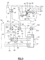
- the anti-theft device 10 shown diagrammatically in FIG. 1 includes a key, or false, key 10 which is intended to come into the barrel, or dummy barrel, of an anti-theft switch 12.
- the switch is designed to equip the dashboard of the vehicle and its design is of a substantially similar type that of the vehicle start switch according to the state of the art.
- the user operates the ignition key 10 or a ring ignition.
- the ignition key 10 is actually a false key in this that it does not necessarily act on a mechanical lock, although such an actual key brings an additional degree safety by adding a locking means or additional chain release with design general of an electric lock.
- the anti-theft switch 12 includes a key 14 which is intended to detect the absence of key 10 or the presence in the introduced position of the latter.
- the switch 12 also includes a switch for multi-position control 16 for controlling the starting the vehicle engine and for controlling the supply of various electrical circuits of the vehicle.
- the key switch 14 is connected by a line 18 to a input of a central anti-theft device 20 while the command 16 is connected by line 22 to another input of the anti-theft control unit 20.
- the anti-theft system has an analysis circuit which is especially able to read the positions occupied by switches 14 and 16 of switch 12.
- the anti-theft system includes, for example, a microcontroller such as an INTEL 8051.
- This circuit contains a input port reader program to inform the central anti-theft device for the positions of the various switches switch 12 as will be explained later.
- the central anti-theft system 20 exchanges signals with an interrogation and reception station 24 which exchanges by lines 26 and 28 signals with, for example, a badge 30 for access without key to the vehicle.
- the anti-theft control unit 20 activates an alarm system forgetting 38.
- the key switch 14 has a movable contact tilting 42 which is permanently connected to the + BAT terminal of the vehicle battery and whose free end cooperates with a fixed contact 44 in the absence of a key, or with a fixed contact 46 when a key 10 is entered in the switch command 12.
- a power supply block 50 of the motor 34 receives locking and unlocking control signals by 32V and 32D lines connected to VER output ports, DEV from the central anti-theft system 20.
- the fixed contact 46 of the key switch 14 is connected by line 18 to a "Request" input port on the central anti-theft device 20 so that it can trigger a sequence to identify the unlock request the lock or the lock request.
- the multi-position control switch 16 is a rotary type switch which includes a movable contact 52 which is permanently connected to the + BAT terminal of the vehicle battery.
- the movable control contact 52 is susceptible successively occupy several offset positions angularly with respect to each other and which are marked “0”, “ACC", "M”, and “D” in the figures.
- the rotary control movable contact 52 is likely to cooperate with one or more arranged conductive tracks in an arc forming the fixed contacts of the switch 16.
- the movable contact 52 When the movable contact 52 is in the ACC position, it cooperates with a fixed track 54 which is electrically connected to the ACC system for vehicle accessories.
- Track 58 is the fixed starter contact DEM of the vehicle combustion engine (not shown) which is connected to the starter in a manner which will be described in more detail by the following.
- This part of the race is delimited by a device inhibition 64 which, in this embodiment, is illustrated in the form of an electromagnet.
- the electromagnet 64 includes a plunger core 66 which is spring loaded permanently by a spring in its extended position illustrated in FIG. 2 in which it does protrusion outside the housing 68 to extend, at the end of the unlocking track 60, facing the contact path mobile 52 to prevent any journey angular of the latter beyond runway 60, towards the ignition track 56 and the starter track 58, as long as the inhibition electromagnet 64 was not supplied with electricity to cause removal of the moving core or plunger 66 of the electromagnet.
- the inhibiting device 64 is therefore arranged in downstream of unlocking runway 60 and upstream of runway 56 and the starter track 58.
- Electric power supply to the electromagnet inhibition 64 is ensured by a power supply unit 70 which is connected directly to the pole + BAT of the battery by a line 72 and which receives control signals for the release of the inhibiting device, i.e. supplying the coil of the electromagnet 64, by a line 74 which is connected to a port of the anti-theft control unit 20.
- the blocking module 76 includes means 78 for detection of the locked or unlocked state of the anti-theft device which issue a signal corresponding to the anti-theft control unit 20.
- the detection means 78 consist of two switches 80, 82 of detection, each in two positions.
- the switch 80 for detecting the unlocking of the anti-theft device comprises a tilting movable contact element 84 which is permanently connected by line 18 to fixed contact 46 of the key switch 14 and it is also connected in Permanently at the "Request" input of the anti-theft control unit 20.
- the movable contact element 84 is capable of cooperate with a first fixed contact 86, when the lock is in its unlocked position, which is connected by a line 87 to an M2D unlock detection input port on the anti-theft system 20 and runway 60.
- the movable contact 84 is in contact with a second fixed contact 88 which is connected to the power input 49 power supply 50 from motor 34 and a door anti-theft control unit V / D input 20.
- the movable contact element 84 of the switch unlocking detection 80 is linked in rotation to the motor 34 which is shown schematically in the figures a movable member 90 which is linked to it in rotation and which is likely to come to cooperate with a mechanical stop of locking 94 and with a mechanical unlocking stop 92.
- the design of the detection switch unlocking 80 is such that the movable contact 84 comes cooperate with the fixed contact 86 before the element 90 does come and cooperate with the mechanical release stop 92.
- the lock detection switch 82 has a tilting movable contact element 96 which is connected in permanently by line 48 at fixed contact 44 of the switch key 14. In the locked position illustrated in Figure 2, the movable contact 96 cooperates with a fixed contact 98 which is connected directly, by a line 99, to an input port of detection of the M1V lock of the anti-theft control unit 20.
- the movable contact element 96 is also susceptible to cooperate with a second fixed contact 100 which is connected in permanence at the V / D input port of the central anti-theft system 20, the power input 49 of the motor power supply 50 34, and at the second fixed contact 88 of the detection switch release 80.
- the electric anti-theft system finally includes a switch muting 102 interposed in line 74 between the central anti-theft device 20 and the power supply unit 70 of the electromagnet inhibition 64.
- the switch 102 comprises a movable contact element tilting 104 which is mechanically linked in rotation to the movable contact element 84 of the detection switch of the unlocking 80.
- the movable contact element 104 is, when the lock is in its locked position, in contact with a fixed contact neutral 108 and is likely to come and make contact electric with a fixed contact 110 when the lock is in its unlocked position, i.e. when the movable element 84 of the unlocking detection switch 80 reaches its unlocking position in contact with the fixed contact 86.
- the mobile contact member 42 is in contact with the fixed contact 46 and it transmits by the line 18 a port unlocking request order input "Request" from the anti-theft control unit 20.
- the change of state of the key switch 14 a also the effect of allowing the electrical supply of the power supply 50 of motor 34 through line 18 and through the unlocking detection switch 80 whose contact fixed 88 is connected to the power input 49.
- the driver then swings the contact switch multiples 16 whose movable control element 52 can rotate to its immediately adjacent angular position ACC in which he is simultaneously in contact with fixed contacts 54 and 60.
- the anti-theft control unit 20 transmits, via its output port VER, a block unlocking control command supply 50 which causes the motor 34 to rotate up to an intermediate position illustrated in FIG. 3 in which the lock detection switch 82 has already changed from position, causing a change of state at the port of entry M1V of the central anti-theft system 20.
- the power supply of block 50 is maintained until the end of unlocking by the contact 60 and the movable element 84 in contact with the fixed stud 88.
- the motor 34 reaches its mechanical unlocking stop 92 and the unlocking detection switch 80 reaches its position illustrated in Figure 4 and simultaneously causes the change of state of muting switch 102.
- movable member 104 of muting switch 102 established line 74 between the central anti-theft system 20 and the block supply 70 of the electromagnet 64 to allow transmit a release signal to the electromagnet 64, signal causing withdrawal of the plunger 66.
- the movable contact 52 is simultaneously in contact with the fixed contact 54 supplying the ACC accessories and with the fixed contact 56 supplying the ALL ignition circuit.
- the driver removes the counterfeit key 10, which has the effect of bringing back the key contact 14 in its position illustrated in FIGS. 2 and 5 in which the movable contact 42 directly connects the terminal + BAT to the contact landline 44 and line 48.
- the anti-theft control unit 20 then transmits via line 32D a lock order to power supply 50 and motor 34, the latter leaving the unlocking position against the mechanical unlocking stop 92 to go to the locking position determined by the mechanical stop of locking 94, the various components then finding their respective positions illustrated in Figure 2.
- unlock detection switch 80 change of state and simultaneously the muting switch 102 changes state to interrupt the connection between the anti-theft control unit 20 and the power supply 70 of the electromagnet 64 again causing the plunger 66 to exit the latter which then again inhibits the access of the element of movable control contact 52 on tracks 56 and 58.
- the invention is in particular not limited to the production a key switch 14 in the form of a switch electric controlled by a false key, this function can be replaced by any other type of switch electric controlled directly or indirectly by the driver.
- the multi-position switch 16 is not necessarily a rotary switch.
Landscapes
- Engineering & Computer Science (AREA)
- Mechanical Engineering (AREA)
- Lock And Its Accessories (AREA)
- Electric Propulsion And Braking For Vehicles (AREA)
Description
- un commutateur d'antivol pour la commande du démarrage du moteur du véhicule et de l'alimentation de différents circuits électriques du véhicule ;
- un antivol motorisé comportant un moteur électrique d'entraínement J'un organe de blocage entre une position verrouillée et une position déverrouillée ; et
- une centrale d'antivol connectée aux éléments précédents pour mettre en oeuvre un procédé de contrôle de l'antivol ;
- un interrupteur de clef pour détecter la simulation de l'introduction d'une clef dans le commutateur d'antivol ; et
- un interrupteur de commande à positions multiples pour commander en séquence l'alimentation de plusieurs circuits électriques du véhicule et du démarreur, comportant un contact mobile de commande relié à une polarité d'une source d'alimentation électrique, et une série de contacts fixes avec lesquels le contact mobile entre successivement en contact lors de la manoeuvre du commutateur en vue de provoquer le démarrage du véhicule, et parmi lesquels le dernier contact fixe est relié notamment au démarreur, l'interrupteur de commande ne pouvant être actionné qu'en présence d'une clef; et
- un dispositif d'inhibition de l'interrupteur de commande qui empêche la venue en contact du contact mobile de commande avec le contact fixe de démarreur tant que l'antivol n'est pas en position déverrouillée et qui, en réponse à un signal de libération provenant de la centrale d'antivol, autorise la venue en contact du contact mobile avec le contact fixe de démarrage.
- un commutateur d'antivol pour la commande du démarrage du moteur du véhicule et de l'alimentation de différents circuits électriques du véhicule ;
- un antivol motorisé comportant un moteur électrique d'entraínement d'un organe de blocage entre une position verrouillée et une position déverrouillée ;
- un interrupteur de clef pour détecter la simulation de l'introduction d'une clef dans le commutateur d'antivol ; et
- un interrupteur de commande à positions multiples pour commander en séquence l'alimentation de plusieurs circuits électriques du véhicule et du démarreur, comportant un contact mobile de commande relié à une polarité d'une source d'alimentation électrique, et une série de contacts fixes avec lesquels le contact mobile entre successivement en contact lors de la manoeuvre du commutateur en vue de provoquer le démarrage du véhicule,
- de coopérer avec un premier contact fixe relié au moteur d'entraínement de l'antivol motorisé, en l'absence de clef et à travers un interrupteur de détection du verrouillage de l'antivol, lorsque l'antivol n'est pas en position verrouillée, et
- de coopérer avec un second contact fixe relié au moteur d'entraínement de l'antivol motorisé, en présence de clef et à travers un interrupteur de détection du déverrouillage de l'antivol, lorsque l'antivol n'est pas en position déverrouillée.
- l'interrupteur de détection du verrouillage de l'antivol comporte un contact mobile relié au premier contact fixe de l'interrupteur de clef et qui est susceptible de coopérer avec un premier contact fixe lorsque l'antivol est en position verrouillée, et de coopérer avec un second contact fixe relié au moteur d'entraínement de l'antivol motorisé, lorsque l'antivol n'est pas en position verrouillée ; et
- l'interrupteur de détection du déverrouillage de l'antivol comporte un contact mobile relié au second contact fixe de l'interrupteur de clef et qui est susceptible de coopérer avec un premier contact fixe lorsque l'antivol est en position déverrouillée, et de coopérer avec un second contact fixe, relié au moteur d'entraínement de l'antivol motorisé, lorsque l'antivol n'est pas en position déverrouillée ;
- l'antivol comporte une centrale d'antivol connectée au commutateur d'antivol et à l'antivol motorisé pour mettre en oeuvre un procédé de contrôle de l'antivol, caractérisé en ce que le second contact fixe de l'interrupteur de clef est relié en permanence à une entrée, de la centrale d'antivol, de détection d'un changement de position du contact mobile de l'interrupteur de clef ;
- le premier contact fixe de l'interrupteur de détection du verrouillage de l'antivol est relié en permanence à une entrée, de la centrale d'antivol, de détection de l'état verrouillé de l'antivol ; et
- le premier contact fixe de l'interrupteur de détection du déverrouillage de l'antivol est relié en permanence à une entrée de la centrale d'antivol, de détection de l'état déverrouillé de l'antivol ;
- le second contact fixe de l'interrupteur de détection de verrouillage de l'antivol et le second contact fixe de l'interrupteur de détection du déverrouillage sont reliés en permanence à une entrée, de la centrale d'antivol, de détection d'un changement d'état de l'antivol.
- La figure 1 est un schéma illustrant un principe de réalisation d'un antivol selon l'état de la technique;
- la figure 2 est un schéma qui illustre un mode de réalisation d'un antivol selon l'invention sur lequel l'antivol électrique est représenté à l'état verrouillé;
- la figure 3 est un schéma similaire à celui de la figure 2 sur lequel l'antivol électrique passe de l'état verrouillé à l'état déverrouillé ;
- la figure 4 est un schéma similaire à celui de la figure 3 sur lequel l'antivol électrique est représenté à l'état déverrouillé ; et
- la figure 5 est un schéma similaire à celui de la figure 2 sur lequel l'antivol passe de l'état déverrouillé à l'état verrouillé .
Claims (5)
- Antivol électrique perfectionné (10), notamment pour un véhicule automobile, du type comportant :et du type dans lequel le commutateur d'antivol (12) comporte :un commutateur d'antivol (12) pour la commande du démarrage (DEM) du moteur du véhicule et de l'alimentation de différents circuits électriques du véhicule (ACC, ALL) ;un antivol motorisé comportant un moteur électrique (34) d'entraínement d'un organe de blocage (36) entre une position verrouillée et une position déverrouillée ;caractérisé en ce que l'interrupteur de clef (14) comporte un contact mobile (42) relié à la source d'alimentation (+BAT) et qui est susceptible :un interrupteur de clef (14) pour détecter la simulation de l'introduction d'une clef (10) dans le commutateur d'antivol (12) ; etun interrupteur de commande (16) à positions multiples pour commander en séquence l'alimentation de plusieurs circuits électriques du véhicule et du démarreur (DEM), comportant un contact mobile de commande (52) relié à une polarité (+BAT) d'une source d'alimentation électrique, et une série de contacts fixes (54, 56, 58) avec lesquels le contact mobile (52) entre successivement en contact lors de la manoeuvre du commutateur (12) en vue de provoquer le démarrage du véhicule,de coopérer avec un premier contact fixe (44) relié au moteur d'entraínement de l'antivol motorisé (34, 50), en l'absence de clef (10) et à travers un interrupteur (82) de détection du verrouillage de l'antivol, lorsque l'antivol n'est pas en position verrouillée, etde coopérer avec un second contact fixe (46) relié au moteur d'entraínement de l'antivol motorisé (34), en présence de clef (10) et à travers un interrupteur (80) de détection du déverrouillage de l'antivol, lorsque l'antivol n'est pas en position déverrouillée.
- Antivol électrique selon la revendication 1, caractérisé en ce que :l'interrupteur (82) de détection du verrouillage de l'antivol comporte un contact mobile (96) relié au premier contact fixe (44) de l'interrupteur de clef (14) et qui est susceptible de coopérer avec un premier contact fixe (98) lorsque l'antivol est en position verrouillée, et de coopérer avec un second contact fixe (100) relié au moteur d'entraínement (34) de l'antivol motorisé, lorsque l'antivol n'est pas en position verrouillée ; et en ce quel'interrupteur (80) de détection du déverrouillage de l'antivol comporte un contact mobile (84) relié au second contact fixe (46) de l'interrupteur de clef (14) et qui est susceptible de coopérer avec un premier contact fixe (86) lorsque l'antivol est en position déverrouillée, et de coopérer avec un second contact fixe (88), relié au moteur d'entraínement (34) de l'antivol motorisé, lorsque l'antivol n'est pas en position déverrouillée.
- Antivol selon l'une des revendications 1 ou 2, caractérisé en ce qu'il comporte une centrale d'antivol (20) connectée au commutateur d'antivol (12) et à l'antivol motorisé, caractérisé en ce que le second contact fixe (46) de l'interrupteur de clef (14) est relié en permanence à une entrée (Demande), de la centrale d'antivol (20), de détection d'un changement de position du contact mobile (42) de l'interrupteur de clef (14) ;
- Antivol selon la revendication 3 prise en combinaison avec la revendication 2, caractérisé en ce que :le premier contact fixe (98) de l'interrupteur (82) de détection du verrouillage de l'antivol est relié en permanence à une entrée (M1V), de la centrale d'antivol, (20) de détection de l'état verrouillé de l'antivol ; et en ce quele premier contact fixe (86) de l'interrupteur (80) de détection du déverrouillage de l'antivol est relié en permanence à une entrée (M2D), de la centrale d'antivol (20), de détection de l'état déverrouillé de l'antivol.
- Antivol selon l'une des revendications 3 ou 4, caractérisé en ce que le second contact fixe (100) de l'interrupteur (82) de détection de verrouillage de l'antivol et le second contact fixe (88) de l'interrupteur (80) de détection du déverrouillage sont reliés en permanence à une entrée (V/D), de la centrale d'antivol (20), de détection d'un changement d'état de l'antivol.
Applications Claiming Priority (2)
| Application Number | Priority Date | Filing Date | Title |
|---|---|---|---|
| FR9503396 | 1995-03-21 | ||
| FR9503396A FR2731969B1 (fr) | 1995-03-21 | 1995-03-21 | Antivol electrique perfectionne, notamment pour un vehicule automobile |
Publications (2)
| Publication Number | Publication Date |
|---|---|
| EP0733525A1 EP0733525A1 (fr) | 1996-09-25 |
| EP0733525B1 true EP0733525B1 (fr) | 2001-07-18 |
Family
ID=9477333
Family Applications (1)
| Application Number | Title | Priority Date | Filing Date |
|---|---|---|---|
| EP96400557A Expired - Lifetime EP0733525B1 (fr) | 1995-03-21 | 1996-03-18 | Antivol électrique perfectionné, notamment pour un véhicule automobile |
Country Status (4)
| Country | Link |
|---|---|
| EP (1) | EP0733525B1 (fr) |
| DE (1) | DE69613879T2 (fr) |
| ES (1) | ES2159699T3 (fr) |
| FR (1) | FR2731969B1 (fr) |
Families Citing this family (1)
| Publication number | Priority date | Publication date | Assignee | Title |
|---|---|---|---|---|
| ES2185489B1 (es) * | 2001-06-18 | 2004-01-16 | Valeo Sist Seguridad Y Cierre | Interruptor de arranque de baja corriente para vehiculos, y equipo de arranque dotado de dicho interruptor. |
Family Cites Families (2)
| Publication number | Priority date | Publication date | Assignee | Title |
|---|---|---|---|---|
| US3735833A (en) * | 1971-10-12 | 1973-05-29 | J Meple Height Sutkowski | Theft prevention device for motor vehicles |
| FR2454503A1 (fr) * | 1979-04-18 | 1980-11-14 | Renault | Appareil de verrouillage electronique, notamment pour antivol |
-
1995
- 1995-03-21 FR FR9503396A patent/FR2731969B1/fr not_active Expired - Fee Related
-
1996
- 1996-03-18 EP EP96400557A patent/EP0733525B1/fr not_active Expired - Lifetime
- 1996-03-18 DE DE69613879T patent/DE69613879T2/de not_active Expired - Fee Related
- 1996-03-18 ES ES96400557T patent/ES2159699T3/es not_active Expired - Lifetime
Also Published As
| Publication number | Publication date |
|---|---|
| FR2731969B1 (fr) | 1997-04-30 |
| ES2159699T3 (es) | 2001-10-16 |
| DE69613879T2 (de) | 2002-04-11 |
| FR2731969A1 (fr) | 1996-09-27 |
| EP0733525A1 (fr) | 1996-09-25 |
| DE69613879D1 (de) | 2001-08-23 |
Similar Documents
| Publication | Publication Date | Title |
|---|---|---|
| EP0733521B1 (fr) | Antivol électrique | |
| FR2740414A1 (fr) | Systeme de communication prevu entre une cle de contact et un vehicule et protege contre les fausses manoeuvres | |
| FR2589930A1 (fr) | Systeme de verrouillage pour voiture, commande par un signal radio | |
| EP1335330A2 (fr) | Système de décondamnation d'ouvrant de véhicule automobile | |
| FR2837766A1 (fr) | Appareil de commande de demarrage du moteur thermique d'un vehicule | |
| EP0733524B1 (fr) | Antivol électrique, notamment pour un véhicule automobile | |
| EP3295380B1 (fr) | Dispositif d'identification sous forme d'anneau muni d'un transpondeur radiofrequentiel | |
| EP0733526B1 (fr) | Antivol électrique perfectionné, notamment pour un véhicule automobile | |
| EP1240059A1 (fr) | Systeme et procede de verrouillage de la direction d'un vehicule | |
| EP0761515B1 (fr) | Système d'antivol électrique, pour un véhicule automobile | |
| EP0733523B1 (fr) | Antivol électrique, notamment pour un véhicule automobile | |
| EP0733522B1 (fr) | Antivol électrique de véhicule automobile | |
| FR2801334A1 (fr) | Systeme de verrouillage electronique | |
| FR2731969A1 (fr) | Antivol electrique perfectionne, notamment pour un vehicule automobile | |
| EP0646506B1 (fr) | Procédé de contrÔle d'un organe antivol de véhicule avec système d'accès par commande à distance, et moyen antivol ainsi constitué | |
| FR2695604A1 (fr) | Dispositif antivol pour tout véhicule muni d'un organe de direction comportant un arbre rotatif transmettant la commande. | |
| EP0596762B1 (fr) | Dispositif antivol de direction pour véhicule automobile, et clé pour un tel dispositif | |
| FR2789632A1 (fr) | Dispositif de commande du demarrage d'un vehicule automobile et procede correspondant | |
| FR2468486A1 (fr) | Dispositif pour l'asservissement du demarrage d'un vehicule automobile a la fermeture d'une ceinture de securite | |
| FR2750097A1 (fr) | Antivol de vehicule automobile a organe apte a agir a distance sur un circuit electrique et vehicule automobile le comportant | |
| FR2733194A1 (fr) | Dispositif antivol de vehicule | |
| FR2764927A1 (fr) | Ensemble de verrouillage / deverrouillage, a distance, des portieres d'un vehicule | |
| WO2000063064A1 (fr) | Equipement antivol de motocyclette | |
| CA3144101A1 (fr) | Coupe-circuit hybride a fonctionnement sequentiel | |
| FR2745538A1 (fr) | Dispositif antivol pour vehicule |
Legal Events
| Date | Code | Title | Description |
|---|---|---|---|
| PUAI | Public reference made under article 153(3) epc to a published international application that has entered the european phase |
Free format text: ORIGINAL CODE: 0009012 |
|
| AK | Designated contracting states |
Kind code of ref document: A1 Designated state(s): DE ES GB IT |
|
| 17P | Request for examination filed |
Effective date: 19970321 |
|
| 17Q | First examination report despatched |
Effective date: 19991124 |
|
| GRAG | Despatch of communication of intention to grant |
Free format text: ORIGINAL CODE: EPIDOS AGRA |
|
| GRAG | Despatch of communication of intention to grant |
Free format text: ORIGINAL CODE: EPIDOS AGRA |
|
| GRAH | Despatch of communication of intention to grant a patent |
Free format text: ORIGINAL CODE: EPIDOS IGRA |
|
| GRAH | Despatch of communication of intention to grant a patent |
Free format text: ORIGINAL CODE: EPIDOS IGRA |
|
| RAP1 | Party data changed (applicant data changed or rights of an application transferred) |
Owner name: VALEO SECURITE HABITACLE |
|
| GRAA | (expected) grant |
Free format text: ORIGINAL CODE: 0009210 |
|
| AK | Designated contracting states |
Kind code of ref document: B1 Designated state(s): DE ES GB IT |
|
| GBT | Gb: translation of ep patent filed (gb section 77(6)(a)/1977) |
Effective date: 20010718 |
|
| REF | Corresponds to: |
Ref document number: 69613879 Country of ref document: DE Date of ref document: 20010823 |
|
| REG | Reference to a national code |
Ref country code: ES Ref legal event code: FG2A Ref document number: 2159699 Country of ref document: ES Kind code of ref document: T3 |
|
| REG | Reference to a national code |
Ref country code: GB Ref legal event code: IF02 |
|
| PLBE | No opposition filed within time limit |
Free format text: ORIGINAL CODE: 0009261 |
|
| STAA | Information on the status of an ep patent application or granted ep patent |
Free format text: STATUS: NO OPPOSITION FILED WITHIN TIME LIMIT |
|
| 26N | No opposition filed | ||
| PGFP | Annual fee paid to national office [announced via postgrant information from national office to epo] |
Ref country code: GB Payment date: 20050304 Year of fee payment: 10 |
|
| PGFP | Annual fee paid to national office [announced via postgrant information from national office to epo] |
Ref country code: DE Payment date: 20050308 Year of fee payment: 10 |
|
| PGFP | Annual fee paid to national office [announced via postgrant information from national office to epo] |
Ref country code: ES Payment date: 20050317 Year of fee payment: 10 |
|
| PG25 | Lapsed in a contracting state [announced via postgrant information from national office to epo] |
Ref country code: GB Free format text: LAPSE BECAUSE OF NON-PAYMENT OF DUE FEES Effective date: 20060318 |
|
| PG25 | Lapsed in a contracting state [announced via postgrant information from national office to epo] |
Ref country code: ES Free format text: LAPSE BECAUSE OF NON-PAYMENT OF DUE FEES Effective date: 20060321 |
|
| PGFP | Annual fee paid to national office [announced via postgrant information from national office to epo] |
Ref country code: IT Payment date: 20060331 Year of fee payment: 11 |
|
| PG25 | Lapsed in a contracting state [announced via postgrant information from national office to epo] |
Ref country code: DE Free format text: LAPSE BECAUSE OF NON-PAYMENT OF DUE FEES Effective date: 20061003 |
|
| GBPC | Gb: european patent ceased through non-payment of renewal fee |
Effective date: 20060318 |
|
| REG | Reference to a national code |
Ref country code: ES Ref legal event code: FD2A Effective date: 20060321 |
|
| PG25 | Lapsed in a contracting state [announced via postgrant information from national office to epo] |
Ref country code: IT Free format text: LAPSE BECAUSE OF NON-PAYMENT OF DUE FEES Effective date: 20070318 |