EP0733250B1 - Differentielles mehrzelliges einbruchlokalisierungskabel - Google Patents
Differentielles mehrzelliges einbruchlokalisierungskabel Download PDFInfo
- Publication number
- EP0733250B1 EP0733250B1 EP95904266A EP95904266A EP0733250B1 EP 0733250 B1 EP0733250 B1 EP 0733250B1 EP 95904266 A EP95904266 A EP 95904266A EP 95904266 A EP95904266 A EP 95904266A EP 0733250 B1 EP0733250 B1 EP 0733250B1
- Authority
- EP
- European Patent Office
- Prior art keywords
- cable
- conductor
- signal
- transmission line
- sense wire
- Prior art date
- Legal status (The legal status is an assumption and is not a legal conclusion. Google has not performed a legal analysis and makes no representation as to the accuracy of the status listed.)
- Expired - Lifetime
Links
Images




Classifications
-
- G—PHYSICS
- G08—SIGNALLING
- G08B—SIGNALLING SYSTEMS, e.g. PERSONAL CALLING SYSTEMS; ORDER TELEGRAPHS; ALARM SYSTEMS
- G08B13/00—Burglar, theft or intruder alarms
- G08B13/22—Electrical actuation
- G08B13/24—Electrical actuation by interference with electromagnetic field distribution
- G08B13/2491—Intrusion detection systems, i.e. where the body of an intruder causes the interference with the electromagnetic field
- G08B13/2497—Intrusion detection systems, i.e. where the body of an intruder causes the interference with the electromagnetic field using transmission lines, e.g. cable
-
- G—PHYSICS
- G08—SIGNALLING
- G08B—SIGNALLING SYSTEMS, e.g. PERSONAL CALLING SYSTEMS; ORDER TELEGRAPHS; ALARM SYSTEMS
- G08B13/00—Burglar, theft or intruder alarms
- G08B13/16—Actuation by interference with mechanical vibrations in air or other fluid
- G08B13/1654—Actuation by interference with mechanical vibrations in air or other fluid using passive vibration detection systems
- G08B13/169—Actuation by interference with mechanical vibrations in air or other fluid using passive vibration detection systems using cable transducer means
-
- F—MECHANICAL ENGINEERING; LIGHTING; HEATING; WEAPONS; BLASTING
- F02—COMBUSTION ENGINES; HOT-GAS OR COMBUSTION-PRODUCT ENGINE PLANTS
- F02B—INTERNAL-COMBUSTION PISTON ENGINES; COMBUSTION ENGINES IN GENERAL
- F02B75/00—Other engines
- F02B75/02—Engines characterised by their cycles, e.g. six-stroke
- F02B2075/022—Engines characterised by their cycles, e.g. six-stroke having less than six strokes per cycle
- F02B2075/025—Engines characterised by their cycles, e.g. six-stroke having less than six strokes per cycle two
Definitions
- the invention relates to coupled transmission line sensors or acoustic cable sensors, and more particularly to a coaxial cable with one or more sense conductors moveable relative to another conductor in response to intruder-caused movement or vibration and a system operative to process a signal coupled to the sense conductor to detect and locate impedance changes of the sense conductor due to the intruder-caused movement or vibration.
- transducer cables All of the foregoing technologies have been used to create line sensors, referred to as “sensor cables”, “transducer cables”, or “acoustic cables”, which act as distributed microphones.
- Typical transducer cable “zone lengths” are from 10 to 300 meters.
- transducer cables have been attached to chain link fences to detect intruders climbing the fences or cutting through them. While some of the prior transducer cables are relatively low cost devices, they result in an excessive number of false alarms due to (1) rain or hail striking the cable, (2) wind blown objects hitting the fence, or (3) the wind induced motion of the fence itself.
- the known transducer cables are buried in the ground to detect seismic activity caused by intruders moving over the cable.
- the inability of detection systems using such transducer cables to accurately distinguish between intruders walking over the cable and vehicular traffic moving at a distance from the cable is a major cause of false alarms. When the number of false alarms is too high, the monitoring service or response force often merely turns the equipment off.
- the transducer cable installer sets a single threshold which must be exceeded to cause an alarm.
- the setting of this threshold always is a compromise. If it is set too low, the number of false alarms is too large. If it is set too high, the probability of detecting an intruder is too low.
- the longer the length of the transducer cable the more difficult the compromise becomes. This is because the longer the transducer cable, the more background noise it picks up, thereby decreasing the signal-to-noise ratio. Also, the longer the transducer cable, the larger is the variation in sensitivity of the cable to physical vibrations along its length of the cable.
- this variation in sensitivity can be due to variations in cable construction, variations in fence conditions, variations in installation, and attenuation in the sensor cable itself.
- sensitivity to physical vibrations is affected by imperfections in cable construction and changes in the properties of the ground or burial medium.
- An electret cable sensor includes a coaxial cable with an electret dielectric, such as Teflon.
- An electret dielectric such as Teflon.
- Teflon an electret dielectric
- a permanent charge is imposed upon the Teflon during the cable fabrication.
- manufacturers simply rely on the charge imposed on the cable during the manufacturing process, while in other cases the charge is deliberately imposed on the cable after it is manufactured by heating the cable to near its melting point and applying a voltage to the cable. This charge will remain in the cable dielectric for many years.
- the known capacitive coupling transducer cables are used by applying a voltage across the conductors of a coaxial cable using a very high impedance source and then detecting minute changes in current therein needed to maintain this voltage while flexing of the cable causes changes in its capacitance. Problems relating to the high impedance sources required for such sensor cables have limited their application.
- An example of a commercially available capacitive coupling sensor cable is a buried sensor cable made by H.E.S.A. of Milan, Italy, based upon U.S. patent 5,068,642 which issued November 26, 1991.
- inductive coupling transducer cables utilize permanent magnetic material with embedded conductors.
- the conductors are allowed to move within a slot in the magnetic material in response to acoustic stimulus, thereby generating a voltage at the end of the sense cable.
- the cost of the magnetic material and the difficulty in manufacturing cable using the magnetic material are the most significant factors in determining the cost of inductive coupling transducer cables.
- An example of a commercially available inductive coupling transducer cable is the GUARDWIRE device produced by Geoquip Corp. of Wirksworth, United Kingdom and sold in the United States by Southwest Microwave Inc. of Tempe, Arizona.
- triboelectric transducer cables are constructed using special plastic materials that generate a voltage when one moves against the other. Coaxial cables made with these materials, when flexed, generate a voltage at their terminations. While the materials in a triboelectric sensor cable are less expensive than those in either an electret or an inductive coupling type transducer cable, their performance is not as easily controlled. The transducer function of triboelectric cables can vary from cable to cable for no apparent reason, and their response voltages are not proportional to the amount of cable motion. Nevertheless, there are many triboelectric sensor cables in use today. A commercially available triboelectric sensor cable is the E-FLEX device produced by Stellar Systems Inc. of Santa Clara California. United States patent 2,787,784 issued April 2, 1957 and Canadian patent 1,160,300 issued January 10, 1984 describe triboelectric transducer cables.
- piezoelectric transducer cables use special plastic materials between two conductors in a coaxial cable construction. When flexed, such plastic materials generate a voltage which can be sensed at the termination of the cable.
- the cost of the special plastic material is the major cost in the construction of the piezoelectric transducer cables.
- An example of a commercially available piezoelectric cable is the FOCUS device manufactured for Focus Ltd. by Chalice Electronics Ltd. of United Kingdom.
- Fiber optic transducer cables were introduced in the 1990's. Flexure of the fiber optic sensor cable alters the transmission of light along an optical fiber, and the effect of such alteration is detected at the end of the line. Fiber optic transducer cables tend to be relatively expensive due to the inherent cost of manufacturing the fiber optics therein.
- An example of a commercially available fiber optic cable sensor is FIBER SENSYS sold by Fiber SenSys, a Corning affiliate in Beaverton, Oregon.
- the present invention includes a means of including the power and data transmission within the transducer cable. This eliminates the need to procure and install separate power and data lines around the perimeter of the protected area to service the multiple sensor "units". Since the transducer cable is tamperproof, the power and data service elements inside the cable are protected. In a closed perimeter system (one which encloses an entire protected area) the power and data can be supplied in both directions around the protected area perimeter to provide redundance.
- My U.S. patent 4,562,428 describes the application of power and data over a two cable CW (continuous wave) leaky coaxial sensor cable. While the transmission of power and data over the transducer cable subsequently described herein has certain similarities to the system described in my patent 4,562,428, the present invention does not utilize leaky coaxial cables.
- electromagnetic waves are used to detect and locate disturbances inside the cable while patent 4,562,428 describes detecting disturbances in the outside air, between the two cables.
- RF radio frequency
- the system described in my patent 4,562,428 uses continuous wave (CW) transmissions with no capability of locating the intruder-caused disturbance along the lengths of the sensor cables.
- My U.S. patent 4,091,367 describes a pulsed leaky coaxial cable sensor. While the RF pulsed disturbance locator system subsequently described herein also uses RF pulses to locate changes in impedance on coupled transmission lines, the present invention does not use leaky coaxial cables. Electromagnetic waves are used to detect and locate disturbance inside the sensor cable as opposed to disturbances in the air outside the cables.
- a transmission line "presence sensor” is described in U. S. patents 3,750,125 and 3,801,976 by Ross et al. These patents describe a coupled strip line sensor in which the object being detected directly perturbs the electromagnetic coupling. This is similar to my leaky coaxial cable sensor described in U. S. patent 4,091,367 except that the lines are in close proximity to each other and are much shorter in length than in leaky coaxial cable sensors. In leaky coaxial cable sensors and the Ross et al device, the fields are not contained inside a cable, and the cable need not be physically disturbed by the target for the target to be detected.
- U. S. patent 4,482,890 by Forbes et al describes a coupled fiber optic sensor for the detection and location of disturbances of a cable encompassing a multiplicity of fibers.
- U. S. patent 5,194,847 by Taylor et al describes a single fiber optic line with a directional coupler.
- the present invention provides a transducer cable according to claim 1, an intrusion detection system comprising the transducer cable, a method of operating the transducer cable, a method of sensing physical movement of a portion of the transducer cable, and a microphonic coupled transmission line sensor system, and in accordance with one embodiment thereof, the invention provides a transducer cable including an inner conductor, an outer conductor, solid dielectric between the inner conductor and the outer conductor, the outer conductor being tubular, the dielectric being within the outer conductor, a longitudinal passage extending through the dielectric material, and a sense wire extending through the passage and loosely fitting therein so that vibration or flexing of the transducer cable results in movement of the sense wire relative to the outer conductor, providing corresponding changes in the impedance of a first transmission line formed by the outer conductor and the sense wire.
- the transducer cable is cylindrical, and the passage is a longitudinal slot in the outer surface of the dielectric.
- a layer of dielectric tape covers the slot.
- the sense wire is flexible multi-strand wire.
- a first termination is matched to the impedance of the first transmission line, and a second termination matched to a characteristic impedance of a second transmission line formed by the inner conductor and the outer conductor.
- a carrier signal is transmitted down the second transmission line, providing an electromagnetic field which couples energy to the first transmission line.
- An intrusion activity that causes movement of the transducer cable results in movement of the sense wire relative to the passage, changing the impedance of the first transmission line and thereby causing a reflection of some of the coupled energy back toward the transmitting circuit and producing a corresponding first signal representative of the reflected energy.
- a receiver circuit is connected to receive the first signal and amplify the first signal and remove high frequency components from it to thereby produce a second signal.
- An analog-to-digital converter receives the second signal, and a control circuit applies a conversion signal to the analog-to-digital converter.
- the conversion signal includes a plurality of convert pulses timed to cause the digital-to-analog converter to digitize values of the second signal representing responses of a plurality of range bin portions of the transducer cable to the second signal.
- a processor receives the digitized values, performs a high pass digital filtering operation on the digitized values to isolate a disturbance component thereof from a clutter response component, and performs an interpolating operation on the isolated disturbance component to determine a peak value and corresponding location along the transducer cable. Then the processor compares the peak value to a corresponding stored threshold value and generate an alarm signal if the peak value exceeds the threshold value.
- the intrusion detection system is calibrated by applying a predetermined mechanical threshold disturbance to the transducer cable at each interpolation point, and operating the system as described above to obtain a threshold stimulus response for each subcell, and storing a corresponding threshold for each interpolation point.
- a second longitudinal passage extends through the dielectric material, and a second sense wire extends through the second passage.
- the second passage is located on the opposite side of the center conductor from the first passage, so that displacement of the transducer cable results in generally opposite relative movement of the first and second sense wires relative to the outer conductor, increasing coupling from the center conductor to the first sense wire and decreasing coupling from the center conductor to the second sense wire.
- Signals reflected from the location of impedance change along the first and second sense wires are differentially sensed by applying them across a primary center tapped winding of a pulse transformer. Common mode noise rejection is thereby achieved, reducing resolution requirements of digital signal processing of the output of the pulse transformer.
- a transducer cable 5 of length L meters comprises an outer conductor 1, a center conductor 2 and a sense wire 3.
- the cable length L typically is between 20 and 200 meters, although it could be as little as 3 meters.
- Sense wire 3 is free to move relative to the outer conductor of the cable 5 within a slot 4 formed in the dielectric material 6.
- An intruder 7 causes a physical disturbance of cable 5 at distance l meters from the beginning thereof.
- the physical motion (i.e., vibrations) of cable 5 at location l causes the "floating" sense wire 3 to move relative to outer conductor 1 within slot 4.
- the physical motion of sense wire 3 is detected and its position is precisely located in order to detect and precisely locate intruder 7.
- Center conductor 2 and outer conductor 1 of transducer cable 5 form an ordinary coaxial cable transmission line 1,2.
- This transmission line is terminated in a resistor 19 of Rc ohms, Rc being the characteristic impedance of the transmission line 1,2.
- Sense wire 3 and outer conductor 1 also form a transmission line 1,3.
- the separation of sense wire 3 from outer conductor 1 varies as sense wire 3 moves within slot 4 relative to outer conductor 1 (due to vibration of cable 5), thereby altering the characteristic impedance of the "sense wire transmission line" 1,3.
- Sense wire 3 is terminated in resistor 18 of Rs ohms, Rs being the average characteristic impedance of sense wire transmission line 1,3.
- Sense wire transmission line 1,3 and coaxial transmission line 1,2 share the same outer conductor 1, so their associated electromagnetic fields occupy much of the same space. Consequently, there is electromagnetic coupling between these two transmission lines.
- a signal imposed upon coaxial cable transmission line 1,2 creates a signal on sense wire 3.
- the degree of coupling depends mainly upon the relative spacing between conductors 1, 2 and 3.
- physical disturbances of transducer cable 5 cause changes in the magnitude of the signal coupled from transmission line 1,2 to transmission line 1,3 at the location of the disturbance. It is this change in the signal coupled from transmission line 1,2 to transmission line 1,3 which is detected and located, to thereby detect and locate intruder 7.
- transducer cable 5 can be any three-conductor line in which appropriate electromagnetic coupling occurs between conductors, it is convenient to use a coaxial construction as illustrated in Fig. 2.
- Conductor 2 is at the center of the cable, surrounded by a cylindrical dielectric sleeve 6.
- Cylindrical conductor 1 is placed about dielectric sleeve 6 to form an outer shield.
- Slot 4 formed in the dielectric sleeve 6 loosely encloses sense wire 3.
- Sense wire 3 therefore "floats" in slot 4, randomly touching all four sides of the slot at various points along the length of transducer cable 5.
- Outer conductor 1 has a very thin insulating layer 43 on its inner surface to prevent shorting between conductors 1 and 3.
- Outer conductor 1 is surrounded by a stout jacket 12 to provide mechanical protection to the cable.
- the jacket 12 can be high density polyethylene, which produces a fairly rigid, non-flaccid cable structure.
- Insulating layer 61 can be composed of aluminum-polyester tape.
- sense wire 3 moves relative to the boundaries of slot 4, altering the impedance of sense wire transmission line 1,3, and therefore also alters the coupling between it and the coaxial transmission line 1,2.
- a standard RG58U type cable was adapted to form transducer cable 5.
- Center conductor 2 is a 20 AWG conductor having a diameter of 0.032 inches.
- the dielectric material or core 6 is solid polyethylene.
- Slot 4 has a width of 0.028 inches and a depth of 0.030 inches.
- Sense wire 3 is a 26 AWG stranded wire formed from seven 34 AWG conductors having an overall diameter of 0.019 inches.
- Polyethylene core 6 is surrounded by a 7/16 inch wide aluminum-polyester tape 61 with the polyester layer on the inside to prevent conductor 3 from shorting to aluminum foil on the outside.
- Aluminum polyester tape 61 can be foil tape produced by Facile Technologies of Paterson New Jersey, having a 0.00092 inch thick polyester film and a 0.00035 inch layer of aluminum. Tape 61 is applied in a "cigarette wrap", with its “overlay” occurring on the opposite side of dielectric core 6 from slot 4. Tinned copper 78 percent braided shield is applied over foil 61, the copper braid making electrical contact with the aluminum side of foil 61. A black solid polyethylene jacket is applied over the braid resulting in a cable with an overall diameter of 0.193 inches. (The use of black jacket material prevents damage due to ultraviolet radiation.)
- slot 4 must be sufficiently large to allow sense wire 3 to move or "float" freely therein.
- the mass and flexibility of sense wire 3 affect its ability to respond to physical disturbances (i.e., intruder-caused vibrations) of transducer cable 5.
- the electrical conductivity and diameter of sense wire 3 determines the attenuation of sense wire transmission line 1,3. While sensor performance may be further optimized by adjusting the slot dimensions and through the use of a different sense wire, the foregoing dimensions were found to be effective.
- the coaxial transmission line 1,2 has a characteristic impedance of 52 ohms.
- the sensor wire transmission line 1,3 has an average characteristic impedance of 60 ohms.
- the coupling loss between these two transmission lines has been found to be approximately 16 decibels.
- Coaxial transmission line 1,2 has a relative velocity of 66%, and the sense wire transmission line 1,3 has a relative velocity of 97%. This results in an average relative velocity of 81.5%.
- the attenuation at 5.8 MHz for coaxial transmission line 1,2 is 6 dB per 100 meters and for sense wire transmission line 1,3 is 10 dB per 100 meters.
- the above described transducer design has proven to be effective for an intrusion detection system.
- the crystal oscillator 20 produces a clock signal which is used to create the RF pulse 8 as well as a sample pulse on conductor 17 upon command from microprocessor 30.
- a frequency of 5.887 MHz clock has a cycle time of 169.85 nanoseconds, although signals from 1 to 100 MHz might be used.
- Microprocessor 30 sends a start command to the logic circuit 21 on line 31 along with a "cell number" N to be sampled on line 32.
- Logic circuit 21 responds by turning on a switch for a number of cycles and by initiating a zero crossing counter (not shown).
- a single cycle RF pulse designated by numeral 8 in Fig. 1 is used in the present invention.
- RF pulse 8 is a 169.85 nanoseconds in duration.
- a switch is turned on until the next zero crossing to generate a 84.925 nanosecond sample pulse.
- This sample pulse is sent on line 17 to the Sample and Hold (S/H) circuit 29 in order to digitize the response signal for the selected cell.
- the time delay between the onset of the RF pulse 8 and the start of the sample pulse is N times the 84.925 nanosecond zero crossing period.
- a single cycle RF square wave pulse produced oy the gate logic 21 is passed through low pass filter 22 to remove the harmonics of the 6.47 MHz pulse, so as to generate a sinusoidal pulse which is amplified in RF amplifier 23 to produce the single cycle sinusoidal RF pulse 8 which is applied to the coaxial transmission line 1,2.
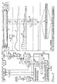
- Signal trace S1 in Fig. 1 depicts RF pulse 8 at an instant of time as it propagates along the coaxial transmission line.
- RF pulse 8 propagates at a velocity of v 2 meters per second where v 2 is less than the free space velocity c of 2.998 x 10 8 meters per second.
- the ratio of v 2 /c is the relative velocity of the coaxial transmission line 1,2 which is essentially the inverse of the square root of the relative permittivity of the dielectric material 6 separating conductors 1 and 2.
- the ratio of v 2 /c is 0.66.
- the RF pulse 8 propagates along the transmission line 1,2 at 0.197868 meters per nanosecond, which is 66% the velocity of light.
- the characteristic impedance, Rc is approximately 52 ohms.
- RF pulse 8 propagates along coaxial transmission line 1,2 energy is coupled into sense wire transmission line 1,3.
- Signals propagate on sense wire transmission line 1,3 at a relative velocity v 3 where v 3 is less than c and more than v 2 .
- Velocity v is higher than v 2 due to the air surrounding sense wire 3 in slot 4.
- v 3 was found to be 0.290806 meters per nanosecond, which is 97% of the velocity of light.
- the forward coupled signal is terminated in matched load 18, which for the cable shown in Fig 2 has a characteristic impedance, Rs, of approximately 60 ohms.
- the coupled signal of particular interest to the detection and location of intruder 7 is the one which is reflected or propagates backwards on sense wire transmission line 1,3 as the RF pulse 8 propagates forward along coaxial transmission line 1,2.
- the time that elapses before the signal reflected at location l returns to the start of cable 5 is l/v 2 , (the time taken for RF pulse 8 to propagate on the coaxial cable 1,2 to location l) plus l/v 3 (the time taken for the reflected pulse to propagate back on the sense wire line 1,3 to the start of cable 5).
- the time difference in the signals arriving back at the start of cable 5 is 10 x(1/v 2 + 1/v 3 ).
- this time period corresponds to the cell width.
- the signal appearing on sense wire 3 at the start of cable 5 is referred to as the "received signal”. It lasts for the length of RF pulse 8 plus L/v 2 plus L/v 3 seconds. For a 169.85 nanosecond pulse and a 200 meter length of cable the received signal lasts for 1.868 microseconds.
- This signal is passed through band pass filter 24 to remove noise outside the band occupied by RF pulse 8.
- the frequency band occupied by a one cycle pulse of a 5.887 MHz signal is from 2.9 to 8.7 MHz.
- the selection of the RF operating frequency is a design compromise.
- the higher the RF operating frequency the more attenuation there is in cable 5.
- the length of cable 5 that can be accommodated is inversely proportional to the cable attenuation, given a processor with a finite dynamic range. An operating frequency of 5.8 MHz seems to be a reasonable compromise.
- band pass filter 24 is amplified by RF amplifier 25 and passed to detector 26 to obtain the "base band" (some times referred to as video) response illustrated as S2 in Fig. 1.
- base band any of the standard types of detectors used in radar could be used, including synchronous and coherent detectors. In the present example, a diode square law detector is used. In effect, this detector receives the RF input signal on sense conductor 3 and produces a base band output that is proportional to the envelope of that RF input signal.
- the number of bits required in the process of digitizing the cable profile determines the dynamic range of the digital signal processing.
- the most significant bit must describe the largest profile at the start of the cable, and the least significant bit must "see" the smallest target change from the end of the cable. Since the target-to-profile ratio combined with the cable attenuation effect is in the order of 60 dB, at least 10 bits and preferably 16 bits of dynamic range are needed to digitize the cable profile. The more bits that are required, the longer the amount of time required for each A/D conversion.
- the feedback circuitry illustrated in Fig. 1 provides a practical means of obtaining the dynamic range of a 16 bit number with the conversion speed of an 8 bit A/D for the digitization of the base band response signal 52. Since the base band signal S2 is virtually stationary once the cable is installed, with only very minor changes occurring due to physical disturbances, it is convenient to use 12 bit digital-to-analog (D/A) converter 28 to feed back the most significant 12 bits, xU j(i-1) , of the most recent 16 bit quantization of the particular cell of interest. (Note that the subscripts j and i are used to denote cell number and sample number, respectively.) The 8 bit A/D converter 33 then can be used to quantize the least significant bits xL ji .
- D/A digital-to-analog
- Differential amplifier 27 subtracts the output of 12 bit D/A converter 28 from the output of detector 26 to provide the desired 24.08 db of gain required to properly "align" the 12 bit D/A converter 28 and 8 bit A/D converter 33. (A gain of 24.08 dB corresponds to a binary shift of exactly 4 bits.)
- the resulting 16 bit number x ji is not "accurate" to 16 bits, but since it has 16 bits of resolution it is well suited to the problem at hand.
- the resulting array of 22 numbers, x ji , j 0,1,2, ...21,22, represents the stationary cable profile plus the cable target response at instant i.
- the above described feedback process provides an adequate dynamic range of 97 dB.
- the MC68HC16Z1 microprocessor includes an A/D converter 33 which can be used to digitize the difference value produced by differential amplifier 27.
- the Sample and Hold (S/H) circuits included in the MC68HC16Z1 microprocessor are not fast enough to capture the 84.925 nanosecond sample required to quantify the base band signal for a 10 meter wide cell, so an external S/H circuit 29 is used to capture the sample from amplifier 27 and hold it while A/D converter 33 inside microprocessor 30 performs the 8-bit A/D conversion, which requires approximately 9 microseconds.
- the microprocessor 30 is used to digitize the 44 data cells associated with two 200 meter lengths of sensor cable 5, approximately 400 microseconds are required. This means that a sample repetition rate of approximately 2.5 KHz can be realized, so each "range cell" value is updated every 400 microseconds.
- FIGs. 3A-C show how "transmit" pulse 8 propagates down coaxial cable 1,2 and how a reflection from a target propagates back on sense wire line 1,3 to the start of cable 5.
- Figures 3A-C show the effect of a target or disturbance 7 at 54, 136 and 200 meters, respectively, from the start of cable 5.
- the horizontal axis in each chart is the distance in meters from the start of cable 5, and the vertical axis is the time in nanoseconds from the onset of transmit pulse 8.
- Lines 50 and 51 represent the leading and trailing edges of target pulse 8 as it propagates down coaxial transmission line 1,2.
- the slope of lines 50 and 51 is determined by the 0.197868 meters/nanosecond velocity of propagation in coaxial transmission line 1,2.
- the leading and trailing edges of the "return pulse" reflected by target 7 are shown as lines 52 and 53 respectively.
- the slope of lines 52 and 53 represents the 0.290806 meters/nanosecond velocity of propagation in the sense wire line 1,3.
- 3C illustrates the case wherein target 7 is located at the end of cable 5 and the return pulse is completed at 1868 nanoseconds, which is the end of range cell 21. From this diagram it is apparent that 22 range cells (0,1,2,...20,21) are required to locate a target within the central 20 range cells, as a target can never appear in range cells 0 or 21 (for a 200 meter length of cable with 10 meter wide cells).
- Each of the samples corresponding to the 22 range cells are passed through a recursive single pole high pass filter algorithm or process represented by block 34 in microprocessor 30 to compute the "response profile" 54 illustrated in Fig. 1. Since in Fig. 1, the disturbance 7 occurred in range cell 14, only range cells 13, 14, and 15 contain significant response values, which are labelled 13, 14, and 15. Note that while all other range cells are shown to have zero responses, there in fact would be small response values in these range cells also, corresponding to system noise. However, these response values would be much less than those in the three range cells 13, 14, and 15, and hence can be disregarded.
- the next step in the digital processing performed by microprocessor 30 is to compute the peak to null value of each response x ji over a time interval of 256 samples.
- the response magnitude, R jk accurately represents the L2 magnitude of the peak-to-peak signal over the kth time interval in cell j (regardless of the subcell). However, there are individual thresholds for each of the 320 subcells along each 200 meter length of sensor cable. Once processor 30 determines the precise subcell location of target 7, the response magnitude R jk can be compared to the threshold T j. ⁇ , ⁇ being the number of the subcell having the peak response to target 7.
- the first step in the algorithm for interpolation of the precise location of the maximum target response is to search the response profile to find the most prominent feature.
- Fig. 4 illustrates the relative target responses in the leading and trailing range cells (a,c) as target 7 is displaced from the center of range cell b.
- Sixteen uniformly displaced situations are illustrated representing the boundaries between 16 subcells of range cell b. While one could use the ratio of response "a” to response “c” to interpolate the location of target 7 within range cell b, it is preferable to use the ratio of "a" to "b” for the bottom 8 subcells and the ratio of "c" to "b” for the top 8 subcells. This minimizes the error associated with noise on the response data by using the responses having the largest values.
- the output of the subcell decision tree is ⁇ , the number of the subcell having the peak response, where 1 ⁇ ⁇ ⁇ 16.
- target 7 is located at cell j and subcell ⁇ . This location is referred to as j. ⁇ , and in the present example is 14.11.
- each subcell is only 0.625 meters (24.6 inches)long and that there are 320 subcells in a 200 meter length of sensor cable. This enables processor 30 to compare the actual target response to the threshold set for that specific location on the perimeter, rather than using a comparison to a single threshold for the entire length of cable, in contrast to all other prior acoustic cable sensor systems.
- a threshold is exceeded, it is highly desirable to require that there be more than M distinct disturbances within a given period of time (say 3 seconds) within the same subcell or within the two adjacent subcells.
- This technique of counting the number of times a threshold is exceeded is used in most prior acoustic cable sensors to eliminate false alarms that otherwise would result from balls or other small objects striking the fence on which the acoustic cable is attached.
- the number of counts M usually is set from 1 to 10.
- Fig. 6 presents typical responses of the present transducer cable 5 to an intruder climbing on a fence on which cable 5 is installed.
- the values of R jk would be the L2 of the three peak-to-peak excursions between points 40 and 41, 42 and 43, and 44 and 45, respectively.
- M With M set to 3, an alarm would be declared if all three "strikes" occurred in the same or neighboring subcells and the three peak-to-peak responses exceed the threshold for the subcells identified. This technique is much more likely to both avoid false alarms and reliably detect real intruders than the "strike counting" techniques used in the prior art where the disturbances can occur at random locations on the cable within the given time window.
- sample and hold circuit 37 and amplifier 38 in Fig. 1 allow such audio assessment of alarm conditions.
- microprocessor 30 would send a signal on conductor 36 to sample and hold circuit 37 to sample and store the analog output of D/A converter 28 at the instant the range cell having the largest target response is being sampled.
- the output of sample and hold circuit 37 is applied to audio amplifier 38 to produce the desired audio output. Note that because this system "locates" the source of the disturbance 7, the output comes only from the range cell at which disturbance 7 occurs, rather than being an average of all acoustic disturbances as for prior acoustic cable sensors.
- this audio output can be sent back over coaxial cable 1,2 to a central location for monitoring.
- microprocessor 30 can be directed to "listen" to any specific range cell on the cable, whereupon it outputs a signal on conductor 36 at the appropriate time to sample the audio from that selected range cell. This capability is not possible with prior acoustic sensor systems.
- Fig. 1 The process illustrated in Fig. 1 is essentially that of an MTI (Moving Target Indicating) radar, but confined to "looking" down transducer cable 5 to detect and locate the disturbances caused by an intruder. Although illustrated as a straight line in Fig. 1, cable 5 can go around corners and up and down hills without affecting the detection and location process.
- MTI Microving Target Indicating
- the signal processing according to the present invention reduces the number of false alarms per length of cable for the following reasons:
- the various thresholds can be lowered to provide a higher probability of detection while preserving an acceptable false alarm rate.
- all thresholds can be increased within certain limits when processor 30 finds a number of large responses at many cable locations within a short period of time, which typically is the case for distributed sources of false alarms. Note that similar "dynamic thresholding" is used in other types of radar.
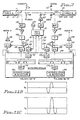
- transducer cable A is designated by numeral 5 and transducer cable B is designated by numeral 105.
- the RF pulse 8 produced by oscillator 20, gate logic 21, low pass filter 22 and amplifier 23 is applied through capacitor 47 to both of transducer cables 5 and 105.
- the receive signal processing hardware 24, 25, 26, 27, 28, 29, 36 ,37 and 38 described previously is duplicated as receive signal processing hardware 124, 125, 126, 127, 128, 129, 136, 137 and 138, respectively.
- Microprocessor 30 has two built-in A/D converter channels with which to process the data from both of transducer cables 5 and 105, respectively.
- A/D converter 33, high pass filter 34 and interpolation and detection algorithm 35 are duplicated by A/D converter 133, high pass filter 134 and interpolation and detection algorithm 135, these are included in the cost of the microprocessor 30 regardless of whether target response signals of one or two transducer cables are to be processed.
- Microprocessor 30 thus can provide separate alarm outputs for cable A and B, as shown.
- transducer cable lengths of 200 meter lengths. In practice, there will be many occasions where shorter cable lengths are required. In such cases, the transducer cable is cut to the desired length, but the processor continues to process data as though there were a 200 meter length of cable.
- microprocessor 30 is programmed to set all thresholds beyond the "calibrated length" to an upper limit value, to thereby avoid any responses from the uncalibrated "imaginary range cells".
- transducer cable 5 protects its own power and data network, which can be made redundant by bringing both ends of the perimeter loop back to a central location.
- the coaxial cable formed by conductors 1 and 2 can be connected together by a series of processor modules such as 91, 92 and 93 in Fig. 8 to provide a path for dc power, audio signals, and low frequency data communications around the entire perimeter of the protected area.
- Capacitors 47 and 48 and inductor 49 as shown in Fig. 7 are used to retrieve the power and data from the path formed by connecting outer conductor 1 to outer conductor 101 and center conductor 2 to outer conductor 102.
- the transducer cables are coupled together by termination units T1 and T2, designated by numerals 94 and 95, respectively.
- the electrical circuit included in each of termination units 94 and 95 is shown in Fig. 9A.
- the sense wire lines 3 and 103 are terminated in matching loads 18 and 118.
- the coaxial center conductors 2 and 102 are terminated at the 5.8 MHz carrier frequency by capacitors 16 and 116 connected in series with resistors 19 and 119, respectively.
- Low pass filter 81 isolates conductor 2 from conductor 102 at the 5.8 MHz carrier frequency, but connects them together at lower frequencies below 1 MHz. This allows dc power, audio signals from 100Hz to 3 KHz and data at 300 KHz and 700 KHz to pass unimpeded from one transducer cable to the next.
- CM 90 control module 90 connected to the ends of the transducer cable paths by ordinary coaxial cable (such as RG58U) by means of end units E1 and E2, designated in Fig. 8 by numerals 96 and 97, respectively.
- the electrical circuit in such end units is illustrated in Fig. 9B.
- Resistor 18 provides a matched load to the sense wire transmission line 1,3.
- Capacitor 16 and resistor 19 provide a matched load to coaxial line 1,2 at the 5.8 MHz carrier frequency.
- Outer conductor 74 of the lead-in cable is connected to outer conductor 1 of the sensor cable.
- Center conductor 73 of the lead-in cable is connected to the center conductor 2 of sensor cable 5 by means of low pass filter 81. In this way power, audio and data signals are passed to the lead-in cable and the RF detection signals are terminated at end unit 96 or 97.
- Such a splice 51 is designated 98 in Fig. 8, and is located between zones Z2 and Z3.
- the circuit in Fig. 9C shows how the splice unit 98 connects the outer conductors 1 and 101, the coaxial center conductors 2 and 102 and the sense wires 3 and 103 of the two sections of transducer cable 5 together.
- bypass unit B1 and B2 designated by numerals 99 and 100, are shown in Fig. 8.
- the circuitry in bypass unit B1 and B2 is shown in Fig. 9D.
- Control module 90 then provides power over the coaxial cable loop to processor modules PM1, PM2 and PM3 in Fig. 8.
- a 24 volt dc supply with battery backup is used at the control module 90 so that the sensor cables 5 continue to operate during AC power outages.
- Voltage regulators are used to derive the 12 volts dc required to power each processor module.
- the 20 AWG solid copper center conductor 2 used in the construction of sensor cable 5 as illustrated in Fig. 2 is the same as used in standard RG58U coaxial cable, and has a dc resistance of 33.1 ohms per kilometer.
- the shield resistance for a 95% braid outer conductor is 13.5 ohms per kilometer. Therefore, the total resistance in the dc power network is 46.6 ohms per kilometer.
- Control module 90 communicates over the loop formed by transducer cable 5 to processor modules PM1, PM2 and PM3.
- Two redundant frequency shift keying (FSK) communication signals are sent at 300 KHz and at 700 KHz along coaxial cable loop 5. By using two unrelated carrier frequencies, nulls due to standing waves on the data loop are avoided.
- the data interface at each processor module and control module 90 is handled by a Motorola MC143150 chip and the LONWORKSTM software produced for this IC chip by Echelon Corporation, Inc. of Palo Alto California. This data network is used to communicate the following data:
- the sensor cables are installed in electrical conduit mounted on a fence.
- a person climbing on the fence causes the conduit to move, thereby flexing the sensor cable and causing an alarm.
- such conduit not only protects the sensor cables, but also the power and data network.
- auxiliary devices such as other sensors or lighting controls or camera controls
- the cable coupler units shown in Figs. 9A-D and each processor module unit shown in Fig. 7 have capacitor 72 coupled to an external port.
- power and data can be supplied in either direction, or in both directions around the perimeter to ensure that most of the system continues operating in the event of a cut cable.
- the guard or response force needs to know where to look for an intruder if the sensor system is to meet its intended purpose. This problem is more complex when closed circuit television is used because the zones should match the field of view of particular cameras if the system is to be effective.
- control module 90 can use this information to define into zones which have no particular relationship to the starts and ends of the sensor cables. Therefore, the sensor system can use the maximum cable length of 400 meters per processor module regardless of the site features thereby substantially reducing the overall system cost in terms of dollars per meter of perimeter while preserving or enhancing the system performance by having as many optimally placed zones as desired.
- control module 90 is programmed to automatically switch the audio from the range cell having the largest target response on the perimeter onto the coaxial cable loop to be monitored at control module 90. In certain cases control module 90 could be programmed to allow the operator to selectively listen to the system response at any selected range cell on the perimeter.
- the audio response is in the 100 Hz to 3 KHz band on the transducer cable loops.
- control module 90 has the data required to produce such a display, preferably on a CRT using a PC (personal computer) graphics software package.
- transducer cable 5 When transducer cable 5 is used as a buried cable sensor, it detects intruders walking over the surface of the ground. A person walking directly over transducer cable 5 causes a "local” disturbance thereof, whereas a distant source causes a more "widespread” disturbance that affects the entire cable. As explained above, microprocessor 29 is able to distinguish between the two types of disturbances, whereas the inability of prior buried line seismic or acoustic sensors to distinguish between local intruders and disturbances caused by distant sources causes prior sensors has resulted in high incidences of false alarms.
- the above described invention provides a relatively low cost transducer cable intrusion detection system which reduces the false alarm rate while improving the probability of detection of a real intruder.
- the described transducer cable incorporates a unique internally coupled highly sensitive dual transmission line structure which allows the system to precisely locate the source of a physical disturbance along the length of the transducer cable, using signal processing techniques to divide the length of the transducer cable into numerous range bins or cells and subcells. This facilitates the described cable calibration procedure that sets individual thresholds which vary along the length of the cable for each subcell defined by an interpolation procedure to overcome variations in transducer sensitivity (which may be caused by cable imperfections, fence condition, installation techniques, the rigidity of the fence fabric near posts etc.) along the length of the cable.
- intruders usually affect only one or two range bins, while most sources of false alarms affect the entire cable, enables microprocessor 30 to avoid many false alarms while improving probability of detection of an intruder.
- transducer cable 5 of the present invention does not rely on external electromagnetic fields to detect the intruder. All of the fields are contained within the single coaxial cable. Transducer cable 5 relies upon the physical coupling of energy from intruders climbing on a fence or cutting through a fence or walking over the soil to cause the disturbance of the sense wire line within the sensor cable to be detected. Because the invention detects disturbances inside the transducer cable, the selection of operating frequency does not need to take into account the radar cross section as when designing a prior art leaky sensor cable. (Most leaky sensor cables operate between 40 and 110 MHz so that a human target is approximately one quarter wavelength long so as to achieve discrimination against small animals.)
- a sense wire can be added to an eccentric coaxial cable. This allows use of a larger diameter sense wire 3 with the same size outer conductor. This has the advantage of reducing attenuation of the sense wire line.
- a sense wire can be added to a shielded twin lead transmission line.
- the transmit pulse 8 is sent down the line in the balanced mode using a tapped transformer.
- the sense wire slot 4 could be located almost anywhere on the circumference of the shielded twin lead.
- the receive signal appears between the sense wire and the outer shield, essentially as in the case in the embodiment of Fig. 2.
- a shielded twin lead in which both conductors are free to move could be used as the transducer cable for the present invention.
- This cable configuration has the advantage of having impedance of both the transmit and receive transmission lines subject to physical motion of the cable. On the other hand it is more expensive to manufacture and the power and data handling capability would be somewhat affected.
- a coaxial cable in which the center conductor is free to move within a cavity can be used as an acoustic cable sensor similar to the present invention.
- a directional coupler is used to isolate the received signal from the transmit pulse.
- the pulse entering the OUT port of the directional coupler appears with little attenuation on the IN port which is connected to the cable. Little of the signal propagating in this direction appears on the CPL (coupled) port.
- the received signal returning on the cable enters the IN port and exits the CPL port with little attenuation. This received signal is essentially the same as the reflected signal described above.
- An electromagnetic waveguide could be used as an acoustic sensor similar to the one described previously herein.
- a directional coupler would be used to isolate the received signal from the transmitted signal.
- reflections are created on the line which can be detected and located in accordance with the present invention.
- Fig. 11A One of the simplest pulse compression techniques for the present invention is illustrated in Fig. 11A.
- the analog received signal shown in Fig. 11B is delayed by one half of the pulse length (80 nanoseconds) and added back to the received signal in a differential mode.
- the response waveform illustrated in Fig. 11C has a sharp peak response that is only half the pulse width long, which in this case corresponds to a 10 meter length of cable. If this pulse compression technique is to be used, the interpolation algorithm is modified to utilize the narrower pulse.
- two or more discrete transmit frequencies can be transmitted on the coaxial cable line, and the amplitude and phase of the received signals can be measured.
- the relative phase angles instead of the time delay measurement described above, can be used to locate the target. While the location of simultaneous multiple targets becomes complicated using this approach, it is often easier to implement and uses less bandwidth. Although the location is in error for simultaneous multiple targets, in many security applications this may be acceptable.
- the present invention has been described in terms of backwards coupled transmission lines inside a cable.
- the transmitter and receiver are at the same end of the sensor cable. It is possible to place the receiver at the opposite end of the cable from the transmitter. In this way, disturbances of the cable are detected as changes in the forward coupled signal. If the sense wire line and the coaxial transmission line have the same attenuation, this approach has the advantage of eliminating the change in response amplitude due to attenuation. This is because the total signal path length from the transmitter to the disturbance and on to the receiver is the same regardless of the location of the disturbance along the length of the cable.
- the response will change with the location of the disturbance, and this change can be used to locate the position of the disturbance. However, this change will be much less than that encountered in the backwards coupled sensor case.
- the coaxial line and the sense wire line have the same velocity of propagation, there is no means of locating the disturbance by monitoring the forward coupled signal. If, on the other hand, the two velocities are different, the target location can be determined by using either a pulsed transmission or a multiple frequency CW transmission.
- the present invention has been described with the transmitted signal being applied to the coaxial transmission line and the receiver attached to the sense wire line. Since this detection system is a linear system, it is reciprocal. In other words, it will detect and locate disturbance equally as well with the transmitter connected to the sense wire and the receiver connected to the coaxial cable line.
- microphonic includes (1) the noise caused by mechanical shock or vibration of elements in a system, and (2) electrical interference caused by mechanical vibration of elements in a signal transmission system.
- Transducer cable 5A is similar to the embodiment of Fig. 10C, in which two floating sense wires are provided.
- the structure shown in Fig. 12 also is similar to the structure shown in Fig. 3, except that an additional slot 4A is provided in dielectric sleeve or core 6. Slot 4A is of the same shape as slot 4, but is diametrically opposed thereto. A second "floating" sense wire 3A is provided in slot 4A.
- transducer cable 5A includes a center conductor 2 terminated in a 50 ohm resistor 19 having resistance in the same fashion as in the embodiment of Fig. 2.
- Floating sense wires 3 and 3A are terminated in 97 ohm resistors 18 and 18A, respectively.
- pulse transformer 75 has one primary winding terminal connected to sense wire 3 and another primary winding terminal connected to sense wire 3A.
- a center tap 75C is connected by a ground conductor to braided outer shield conductor 1.
- One terminal of secondary winding 75B of transformer 75 is connected to ground, the other being connected to the RX conductor 76.
- RX conductor 76 is connected to signal processing circuitry subsequently described with reference to Fig. 1.
- slots 4 and 4A could be made deeper, and perhaps also narrower.
- Dual floating sense wire transducer cable 5A of Figs. 12 and 13 provides the substantial advantage (over the embodiment of Figs. 1 and 2) that common mode noise rejection of the clutter signal or background noise on sense wires 3 and 3A is accomplished, and differential sensing of the reflected target signals on sense wires 3 and 3A also is accomplished.
- This is illustrated by the timing diagram of Fig. 14 wherein numerals 9 and 9A indicate the clutter or base band responses of sense wires 3 and 3A.
- Dotted line 10 indicates the amount by which the target response of sense wire 3 differs from its clutter response when transducer cable 5A is deflected at a point l along its length L.
- Dotted line 10A indicates the target response of diametrically opposed sense wire 3A.
- differential sensing accomplished by the primary winding connection of transformer 75 shown in Fig. 13 has the advantage of providing electrical isolation between the RX conductor 76 and the center conductor 2, thereby providing protection from lightning-caused transients, etc. for the signal processing circuitry, it should be appreciated that a differential amplifier could be used instead to accomplish the clutter response cancellation and differential sensing of the combined target responses of sense wires 3 and 3A.
- the common mode noise rejection of the differential floating sense wire configuration of Figs. 12 and 13 results in the substantial advantage of reducing the dynamic range requirement of the signal processing circuitry.
- the resolution of the digitizing circuitry therein can be reduced from 14 bits to 10 bits.
- the additional cost of the pulse transformer 75 is much less than the increased cost of digitizing circuitry necessary to accomplish the needed resolution (roughly 16 bits) if the small target response is included with the relatively large clutter response.
- the previously mentioned problems associated with the increased sensitivity associated with the start and end portions of the transducer cable are avoided by the differential sensing.
- the reduced dynamic range requirements and differential sensing also make the system much less sensitive to variations in output TX of the transmit circuitry.
- the two floating sense wires are effectively coupled and parallel, and nicely match the 50 ohm impedance of the coaxial transmission line.
- the "audio" response from a particular cell it can be processed to enhance the signal to increase the probability of detection and to reject false alarms.
- Most of the techniques developed for speech recognition can be applied. For example, a "short time average zero-crossing rate" such as described in Digital Processing of Speech Signals by L. R. Rabiner and R. W. Schafer, published by Prentice-Hall Inc., can be used to estimate the dominant frequency content of the response burst. In this case it is the natural frequency of the wires vibrating in the keyways. Since this frequency information is correlated both in time and along the cable for a specific disturbance, it can be used to enhance performance. In fact, nearly all of the speech recognition techniques in use today can be applied to recognized alarm responses and to eliminate known sources of false alarms such as rain or wind on a fence mounted sensor.
- One embodiment of the present invention uses the phase angle of a Continuous Wave (CW) transmission to detect and locate the disturbance of the cable.
- CW Continuous Wave
- CW radar such as a radar altimeter
- an impulse or step function can be transmitted much like a Time Domain Reflectometer (TDR).
- TDR Time Domain Reflectometer
Landscapes
- Physics & Mathematics (AREA)
- General Physics & Mathematics (AREA)
- Electromagnetism (AREA)
- Burglar Alarm Systems (AREA)
- Geophysics And Detection Of Objects (AREA)
Claims (15)
- Signalgeberkabel (5), das einen ersten Leiter (2), einen zweiten Leiter (1) und ein festes, nichtmagnetisches dielektrisches Material (6) zwischen dem ersten Leiter und dem zweiten Leiter enthält, gekennzeichnet durch:(a) einen ersten longitudinalen Kanal (4), der sich durch das nichtmagnetische dielektrische Material erstreckt; und(b) einen ersten Lesedraht (3), der sich durch den ersten longitudinalen Kanal erstreckt und lose darin liegt, so daß eine physische Bewegung des Signalgeberkabels eine Bewegung des ersten Lesedrahts in Bezug auf den ersten oder zweiten Leiter zur Folge hat, was entsprechende Änderungen in der Impedanz einer durch den ersten Lesedraht und den ersten oder zweiten Leiter gebildeten ersten Übertragungsleitung ergibt.
- Signalgeberkabel nach Anspruch 1, worin der erste Leiter (2) ein innerer Leiter ist und der zweite Leiter (1) ein äußerer Leiter ist, wobei der äußere Leiter röhrenförmig und das dielektrische Material innerhalb des äußeren Leiters ist.
- Signalgeberkabel (5A) nach Anspruch 1 oder 2, gekennzeichnet durch einen zweiten longitudinalen Kanal (4A), der sich durch das dielektrische Material erstreckt, und einen zweiten Lesedraht (3A), der sich durch den zweiten longitudinalen Kanal erstreckt und lose darin liegt, so daß eine physische Bewegung des Signalgeberkabels eine Bewegung in im wesentlichen entgegengesetzte Richtungen des ersten und zweiten Lesedrahtes in Bezug auf den ersten oder zweiten Leiter zur Folge hat, was wesentliche entsprechende Änderungen in der Impedanz der durch den ersten Lesedraht und den ersten oder zweiten Leiter gebildeten ersten Übertragungsleitung und wesentliche entsprechende Änderungen in der Impedanz einer durch den zweiten Lesedraht und den ersten oder zweiten Leiter gebildeten zweiten Übertragungsleitung zur Folge hat.
- Eindringnachweissystem mit dem Signalgeberkabel nach einem der Ansprüche 1 bis 3.
- Eindringnachweissystem nach Anspruch 4, worin das Signalgeberkabel (5) als dritten Leiter den Lesedraht (3) und das dielektrische Material (6) zwischen dem ersten, zweiten und dritten Leiter enthält, gekennzeichnet durch:(a) den dritten Leiter, der sich in Bezug auf-den ersten und zweiten Leiter ungehindert bewegt, so daß eine physische Bewegung des Signalgebersignals eine Bewegung des dritten Leiters in Bezug auf den ersten und zweiten Leiter zur Folge hat, wodurch entsprechende Änderungen in der Impedanz einer durch den dritten Leiter (3) und den ersten Leiter (2) gebildeten ersten Übertragungsleitung (3, 2) verursacht werden, wobei eine zweite Übertragungsleitung (1, 2) durch den zweiten Leiter (1) und den ersten Leiter (2) gebildet wird;(b) eine Sendeschaltung (20), die dafür eingerichtet ist, ein HF-Signal die zweite Übertragungsleitung hinab zu senden, wobei ein elektromagnetisches Feld in der zweiten Übertragungsleitung durch die Kopplungsenergie des HF-Signals mit der ersten Übertragungsleitung erzeugt wird und ein Eindringvorgang eine Bewegung des Signalgeberkabels hervorruft, die eine Bewegung des dritten Leiters in Bezug auf den ersten (2) und zweiten (1) Leiter zur Folge hat und eine Impedanz der ersten Übertragungsleitung (3, 2) an einem Abschnitt davon ändert, an welchem die Relativbewegung auftritt, wobei der dritte Leiter (3) ein erstes Signal trägt, das die Impedanzänderung repräsentiert; und(c) eine Empfängerschaltung (26), die angeschlossen ist, um das erste Signal zu empfangen, und betriebsfähig ist, ein zweites Signal zu erzeugen, das für das Auftreten des Eindringvorgangs repräsentativ ist.
- Eindringnachweissystem nach Anspruch 5, mit einem ersten (4) und zweiten (4A) longitudinalen Kanal, die sich durch das dielektrische Material erstrecken, und dem dritten Leiter (3) und einem vierten Leiter (3A), die sich durch den ersten bzw. zweiten longitudinalen Kanal erstrecken und darin lose liegen, so daß eine physische Bewegung des Signalgeberkabels (5A) eine Bewegung des dritten (3) und vierten (3A) Leiters in im wesentlichen entgegengesetzte Richtungen in Bezug auf den ersten Leiter (2) zur Folge hat, was entsprechende Änderungen in der Impedanz der ersten Übertragungsleitung und einer dritten Übertragungsleitung verursacht, die durch den vierten Leiter (3A) und den ersten Leiter (2) gebildet wird;
wobei ein elektromagnetisches Feld entlang dem ersten Leiter (2) durch das HF-Signal und die Kopplungsenergie mit der ersten und zweiten Übertragungsleitung erzeugt wird, wobei ein Eindringvorgang eine Bewegung des Signalgeberkabels (5A) hervorruft, die eine Bewegung des dritten (3) und vierten (3A) Leiters im ersten (4) bzw. zweiten (4A) longitudinalen Kanal in im wesentlichen entgegengesetzte Richtungen in Bezug auf den ersten Leiter zur Folge hat und Impedanzen der ersten und zweiten Übertragungsleitung an einem Abschnitt davon mit der Relativbewegung ändert, wobei die Impedanzänderungen eine Reflexion eines Teils der eingekoppelten Energie zurück entlang der ersten und zweiten Übertragungsleitung in Richtung auf die Sendeschaltung verursachen und der dritte und vierte Leiter ein differentielles erstes Signal tragen, das die reflektierte Energie repräsentiert;
wobei die Empfängerschaltung angeschlossen ist, um das differentielle erste Signal zu empfangen, und betriebsfähig ist, ein zweites Signal zu erzeugen, das für das Stattfinden des Vorgangs repräsentativ ist. - Eindringnachweissystem nach Anspruch 6, worin der erste Leiter (2) ein innerer Leiter ist und der zweite Leiter (1) ein äußerer Leiter ist, wobei der äußere Leiter röhrenförmig und das dielektrische Material innerhalb des äußeren Leiters ist;
wobei die Empfängerschaltung betriebsfähig ist, um Hochfrequenzkomponenten vom ersten Signal zu verstärken und zu filtern, um dadurch ein zweites Signal zu erzeugen, wobei das Eindringnachweissystem einen Analog-Digital-Wandler (33) einschließt, der angeschlossen ist, um das zweite Signal zu empfangen;
eine Steuerschaltung angeschlossen ist, um ein Umwandlungssignal an den Analog-Digital-Wandler anzulegen, wobei das Umwandlungssignal mehrere Impulse enthält, die zeitlich so abgestimmt sind, um den Analog-Digital-Wandler zu veranlassen, Werte des zweiten Signals zu digitalisieren, die jeweils Antworten mehrerer verschiedener Abschnitte des Signalgeberkabels auf das zweite Signal repräsentieren; und
ein Prozessor (30) dafür eingerichtet ist, die digitalisierten Werte zu empfangen, eine digitale Hochpaß-Filteroperation an den digitalisierten Werten durchzuführen, um eine Störungskomponente aus deren Clutter-Antwortkomponente zu isolieren, eine Interpolationsoperation an der isolierten Störungskomponente durchzuführen, um einen Spitzenwert und eine entsprechende Stelle entlang dem Signalgeberkabel zu bestimmen, den Spitzenwert mit einem gespeicherten Schwellenwert für die entsprechende Stelle zu vergleichen und ein Alarmsignal zu erzeugen, falls der Spitzenwert den Schwellenwert übersteigt. - Eindringnachweissystem nach Anspruch 7, worin das dielektrische Material ungefähr zylindrisch ist und der erste und zweite langgestreckte Kanal langgestreckte Schlitze sind, die sich durch gegenüberliegende äußere Teile des dielektrischen Materials erstrecken.
- Eindringnachweissystem nach Anspruch 8, worin das Signalgeberkabel ferner eine Schicht eines dielektrischen Bandes (61) enthält, das den ersten und zweiten Schlitz bedeckt, und worin der dritte und vierte Leiter biegsame Mehrleiterdrähte sind, das Signalgeberkabel einen ersten Abschluß (18A) enthält, der an eine charakteristische Impedanz der ersten Übertragungsleitung angepaßt ist, und einen zweiten Abschluß (18), der an eine charakteristische Impedanz der zweiten Übertragungsleitung angepaßt ist.
- Verfahren zum Betreiben des Signalgeberkabels (5) nach Anspruch 1 in einem Eindringnachweissystem nach Anspruch 4, wobei das Verfahren gekennzeichnet ist durch:(a) Vorsehen des longitudinalen Kanals (4), der sich durch das dielektrische Material ungefähr parallel zum ersten und zweiten Leiter erstreckt, und Vorsehen des Lesedrahtes (3), der sich durch den Kanal erstreckt und darin lose liegt, wobei der Lesedraht und der erste Leiter die erste Übertragungsleitung bilden;(b) physisches Bewegen des Kabels als Antwort auf einen Eindringvorgang; und(c) Bewegen des Lesedrahtes innerhalb des Kanals, was daher eine Bewegung des Lesedrahtes in Bezug auf den ersten und zweiten Leiter verursacht, wodurch eine entsprechende Änderung einer Impedanz zwischen dem Lesedraht und dem zweiten Leiter hervorgerufen wird.
- Verfahren nach Anspruch 10, mit den Schritten:Senden eines Trägersignals von einem ersten Ende des Signalgeberkabels eine durch den ersten Leiter und den zweiten Leiter gebildete zweite Übertragungsleitung hinab;Einkoppeln von Energie vom früheren Signal in die erste Übertragungsleitung; undReflektieren eines Teils der eingekoppelten Energie an der Stelle der Impedanzänderung;Messen eines ersten Signals, das durch die reflektierte Energie auf dem Lesedraht erzeugt wird; undBestimmen der Stelle der Bewegung durch Messen des Zeitbetrags, der erforderlich ist, damit das erste Signal sich von der Stelle der Impedanzänderung zum ersten Ende des Signalgeberkabels fortpflanzt.
- Verfahren zum Erfassen einer physischen Bewegung eines Abschnitts des Signalgeberkabels (5) nach Anspruch 1, wobei das Verfahren gekennzeichnet ist durch:(a) Vorsehen des Kanals (4) durch das Dielektrikum, das sich entlang der Länge des Signalgeberkabels erstreckt, und Plazieren des ersten Lesedrahtes so, daß er durch den Kanal verläuft, wobei der Lesedraht lose im Kanal liegt, so daß die physische Bewegung und anschließende relative Querbewegung des Lesedrahtes im Kanal eine Impedanzänderung einer durch den ersten Leiter und den Lesedraht gebildeten ersten Übertragungsleitung an der Stelle der Bewegung zur Folge hat;(b) Senden eines Trägersignals von einem ersten Ende des Signalgeberkabels eine durch den ersten Leiter und den zweiten Leiter gebildete zweite Übertragungsleitung hinab;(c) Einkoppeln einer Energie vom Trägersignal in die erste Übertragungsleitung und Reflektieren eines Teils der eingekoppelten Energie an der Stelle;(d) Messen eines ersten Signals, das auf dem Lesedraht durch die reflektierte Energie erzeugt wird; und(e) Bestimmen der Stelle der Bewegung durch Messen eines Zeitbetrags, der erforderlich ist, damit sich das erste Signal von der Stelle der Bewegung zum ersten Ende des Signalgeberkabels fortpflanzt.
- Mit einem Mikrophon gekoppeltes Sensorsystem mit Übertragungsleitungen, das in Kombination aufweist:(a) ein Kabel nach Anspruch 1, wobei das Kabel zwei Übertragungsleitungen (2, 3 und 2, 3A) enthält, die durch drei ungefähr parallele Leiter gebildet werden, worin ein dritter (3) der Leiter sich als Antwort auf eine physische Störung des Kabels in Bezug auf den ersten (2) Leiter ungehindert bewegt;(b) einen Hochfrequenzsender (20), der mit einer der Übertragungsleitungen an einem ersten Ende des Kabels verbunden ist; und(c) einen Hochfrequenzempfänger (26), der mit einer der Übertragungsleitungen verbunden ist, um eine Änderung in der Kopplung zwischen den beiden Übertragungsleitungen nachzuweisen, die durch eine physische Störung des Kabels hervorgerufen wird, und das Vorhandensein der physischen Störung als Antwort auf die Änderung anzuzeigen.
- Mit einem Mikrophon gekoppeltes Sensorsystem mit Übertragungsleitungen nach Anspruch 13, worin sich der Sender und Empfänger am ersten Ende des Kabels befinden, wobei der Empfänger ein reflektiertes gekoppeltes Signal empfängt.
- Mit einem Mikrophon gekoppeltes Sensorsystem mit Übertragungsleitungen nach Anspruch 14, worin der Sender einen Impuls eines Hochfrequenzsignals eine der Übertragungsleitungen hinab sendet und der Empfänger eine Zeitverzögerung bis zum Empfang der Änderung mißt, die durch die physische Störung hervorgerufen wird, um die Störung entlang der Länge des Kabels zu lokalisieren.
Applications Claiming Priority (5)
| Application Number | Priority Date | Filing Date | Title |
|---|---|---|---|
| US08/164,364 US5448222A (en) | 1993-12-09 | 1993-12-09 | Coupled transmission line sensor cable and method |
| US164364 | 1993-12-09 | ||
| US296666 | 1994-08-26 | ||
| US08/296,666 US5446446A (en) | 1993-12-09 | 1994-08-26 | Differential, multiple cell reflex cable intrusion detection system and method |
| PCT/US1994/014056 WO1995016251A1 (en) | 1993-12-09 | 1994-12-07 | Differential multi-cell intrusion locating cable |
Publications (3)
| Publication Number | Publication Date |
|---|---|
| EP0733250A1 EP0733250A1 (de) | 1996-09-25 |
| EP0733250A4 EP0733250A4 (de) | 1999-12-01 |
| EP0733250B1 true EP0733250B1 (de) | 2004-07-21 |
Family
ID=26860491
Family Applications (1)
| Application Number | Title | Priority Date | Filing Date |
|---|---|---|---|
| EP95904266A Expired - Lifetime EP0733250B1 (de) | 1993-12-09 | 1994-12-07 | Differentielles mehrzelliges einbruchlokalisierungskabel |
Country Status (5)
| Country | Link |
|---|---|
| US (1) | US5446446A (de) |
| EP (1) | EP0733250B1 (de) |
| CA (1) | CA2177691C (de) |
| DE (1) | DE69433909T2 (de) |
| WO (1) | WO1995016251A1 (de) |
Cited By (2)
| Publication number | Priority date | Publication date | Assignee | Title |
|---|---|---|---|---|
| RU2653307C1 (ru) * | 2017-08-14 | 2018-05-07 | Российская Федерация, от имени которой выступает Государственная корпорация по атомной энергии "Росатом" (Госкорпорация "Росатом") | Система охранной сигнализации на основе излучающего кабеля |
| RU2712648C1 (ru) * | 2019-05-08 | 2020-01-30 | Федеральное государственное казенное образовательное учреждение высшего образования "Калининградский пограничный институт Федеральной службы безопасности Российской Федерации" | Способ распознавания типа нарушителя инфракрасным средством обнаружения |
Families Citing this family (33)
| Publication number | Priority date | Publication date | Assignee | Title |
|---|---|---|---|---|
| US5629681A (en) * | 1993-03-01 | 1997-05-13 | Automotive Technologies International, Inc. | Tubular sonic displacement sensor |
| US6215888B1 (en) * | 1998-06-10 | 2001-04-10 | At&T Corp. | Cable location method and apparatus using modeling data |
| US8483262B2 (en) * | 2000-03-10 | 2013-07-09 | Radio System Corporation | Piezoelectric cable perimeter monitoring system |
| US20080074259A1 (en) * | 2000-09-21 | 2008-03-27 | Robert Houston | Solar powered security system |
| FI109625B (fi) * | 2000-10-09 | 2002-09-13 | Increa Oy | Järjestely kontaktin havaitsemiseen |
| US6417769B1 (en) * | 2001-03-27 | 2002-07-09 | Te-Chin Jan | Voice-controlled burglarproof device |
| US6621562B2 (en) * | 2001-09-26 | 2003-09-16 | Tempo Research Corporation | Time domain reflectometer with wideband dual balanced duplexer line coupling circuit |
| CA2408573C (en) * | 2001-10-17 | 2011-12-20 | Andre Gagnon | Intruder/escapee detection system |
| US6967584B2 (en) * | 2003-07-28 | 2005-11-22 | Senstar-Stellar Corporation | Integrated sensor cable for ranging |
| WO2005013223A1 (en) * | 2003-08-01 | 2005-02-10 | Senstar-Stellar Corporation | Cable guided intrusion detection sensor, system and method |
| US7184907B2 (en) * | 2003-11-17 | 2007-02-27 | Fomguard Inc. | Apparatus and method to detect an intrusion point along a security fence |
| FR2870984B1 (fr) * | 2004-05-28 | 2006-08-04 | Sfp Security Fence Perimeter S | Fil de cloture et dispositif de detection d'intrusion muni de celui-ci |
| US7479878B2 (en) * | 2004-07-28 | 2009-01-20 | Senstar-Stellar Corporation | Triboelectric, ranging, or dual use security sensor cable and method of manufacturing same |
| US7069160B2 (en) * | 2004-08-31 | 2006-06-27 | Cecil Kenneth B | Intrusion detection system and method thereof |
| US20100207744A1 (en) * | 2004-11-10 | 2010-08-19 | Caterpillar Inc. | System And Method For Power And Data Delivery On A Machine |
| US20060097852A1 (en) * | 2004-11-10 | 2006-05-11 | Lammers Bryan G | System and method for power and data delivery on a machine |
| US7256727B2 (en) * | 2005-01-07 | 2007-08-14 | Time Domain Corporation | System and method for radiating RF waveforms using discontinues associated with a utility transmission line |
| SI1856237T1 (sl) * | 2005-03-10 | 2020-12-31 | Obagi Cosmeceuticals Llc | Stabilne organske sestave peroksida |
| US20060239603A1 (en) * | 2005-06-13 | 2006-10-26 | Optellios Inc. | Distributed sensor system coupled with a plurality of secondary sensors |
| CN101563714A (zh) * | 2006-09-25 | 2009-10-21 | 太阳光线安全公司 | 太阳能供电的安全系统 |
| US7728725B2 (en) * | 2007-03-05 | 2010-06-01 | Cecil Kenneth B | Intrusion detection system for underground/above ground applications using radio frequency identification transponders |
| US7741853B2 (en) * | 2007-09-28 | 2010-06-22 | Rockwell Automation Technologies, Inc. | Differential-mode-current-sensing method and apparatus |
| WO2009088155A1 (en) * | 2008-01-04 | 2009-07-16 | Rae-Woong Park | Crimes and disasters preventing system |
| US8848810B2 (en) * | 2008-03-05 | 2014-09-30 | Qualcomm Incorporated | Multiple transmitter system and method |
| US7777496B2 (en) * | 2008-07-18 | 2010-08-17 | The United States Of America As Represented By The Secretary Of The Army | Remote sensor system for monitoring the condition of earthen structure and method of its use |
| FR2966958A1 (fr) | 2010-10-29 | 2012-05-04 | Sorhea | Cloture avec detection localise d'intrusion. |
| US20120326867A1 (en) * | 2011-06-24 | 2012-12-27 | Maximum Controls, L.L.C. | System and method for sensing a gate tampering |
| CN106415681A (zh) * | 2014-05-15 | 2017-02-15 | 梅罗·塔西西奥卡达 | 防止行人和/或没有车厢的一般车辆闯入限制接近区域且允许具有车厢的车辆、包括具有封闭机罩的敞篷车辆接近的系统和方法 |
| CZ2014391A3 (cs) * | 2014-06-06 | 2016-01-20 | Vesys Electronics S.R.O. | Multifunkční smart kabel pro detekci fyzikálních veličin nebo jejich změn |
| WO2017193201A1 (en) | 2016-05-12 | 2017-11-16 | Fiber Sensys, Inc. | Mimo cable guided intrusion detection sensor |
| GB2551391A (en) * | 2016-06-17 | 2017-12-20 | Crh Fencing & Security Group (Uk) Ltd | An apparatus and system for sensing movement |
| FR3115953B1 (fr) * | 2020-11-05 | 2022-10-28 | Thales Sa | Dispositif de réception d'ondes acoustiques |
| CN113624929B (zh) * | 2021-10-12 | 2022-01-25 | 成都千嘉科技有限公司 | 一种气体传感器全量程自动标定方法 |
Family Cites Families (16)
| Publication number | Priority date | Publication date | Assignee | Title |
|---|---|---|---|---|
| US3384887A (en) * | 1965-09-03 | 1968-05-21 | Sylvania Electric Prod | Intruder detection system |
| US3763482A (en) * | 1971-02-01 | 1973-10-02 | Gte Sylvania Inc | Coaxial cable transducer |
| US3750125A (en) * | 1971-10-20 | 1973-07-31 | Sperry Rand Corp | Transmission line presence sensor |
| US3801976A (en) * | 1971-12-06 | 1974-04-02 | Sperry Rand Corp | Transmission line presence sensor |
| US4091367A (en) * | 1974-02-28 | 1978-05-23 | Robert Keith Harman | Perimeter surveillance system |
| US4023155A (en) * | 1975-12-23 | 1977-05-10 | Gte Sylvania Incorporated | Ultrasonic tape intrusion detection system |
| US4197529A (en) * | 1978-02-17 | 1980-04-08 | The United States Of America As Represented By The Secretary Of The Navy | Intrusion detection apparatus |
| US4374299A (en) * | 1980-05-19 | 1983-02-15 | Belden Corporation | Triboelectric transducer cable |
| US4482890A (en) * | 1981-01-22 | 1984-11-13 | The Secretary Of State For Defence In Her Britannic Majesty's Government Of The United Kingdom Of Great Britain And Northern Ireland | Weight responsive intrusion detector using dual optical fibers |
| CA1216340A (en) * | 1982-05-14 | 1987-01-06 | Dale R. Younge | Intrusion detector |
| US4571578A (en) * | 1983-04-19 | 1986-02-18 | The United States Of America As Represented By The Secretary Of The Air Force | Intrusion barrier and detection apparatus |
| GB2175771B (en) * | 1985-04-17 | 1989-01-11 | Geoquip Security Systems Ltd | Vibration sensitive transducer |
| CA1301277C (en) * | 1988-09-27 | 1992-05-19 | R. Keith Harman | Phase shift divided leaky cable sensor |
| US4906975A (en) * | 1988-11-18 | 1990-03-06 | Mrm Security Systems, Inc. | Vibration responsive intrusion detection barrier |
| IT1229151B (it) * | 1989-04-07 | 1991-07-22 | Hesa Spa | Dispositivo di allarme o di segnalazione il cui elemento sensore e' costituito da un cavo coassiale schermato polarizzato in corrente continua |
| US5194847A (en) * | 1991-07-29 | 1993-03-16 | Texas A & M University System | Apparatus and method for fiber optic intrusion sensing |
-
1994
- 1994-08-26 US US08/296,666 patent/US5446446A/en not_active Expired - Lifetime
- 1994-12-07 CA CA002177691A patent/CA2177691C/en not_active Expired - Lifetime
- 1994-12-07 WO PCT/US1994/014056 patent/WO1995016251A1/en not_active Ceased
- 1994-12-07 DE DE69433909T patent/DE69433909T2/de not_active Expired - Lifetime
- 1994-12-07 EP EP95904266A patent/EP0733250B1/de not_active Expired - Lifetime
Cited By (2)
| Publication number | Priority date | Publication date | Assignee | Title |
|---|---|---|---|---|
| RU2653307C1 (ru) * | 2017-08-14 | 2018-05-07 | Российская Федерация, от имени которой выступает Государственная корпорация по атомной энергии "Росатом" (Госкорпорация "Росатом") | Система охранной сигнализации на основе излучающего кабеля |
| RU2712648C1 (ru) * | 2019-05-08 | 2020-01-30 | Федеральное государственное казенное образовательное учреждение высшего образования "Калининградский пограничный институт Федеральной службы безопасности Российской Федерации" | Способ распознавания типа нарушителя инфракрасным средством обнаружения |
Also Published As
| Publication number | Publication date |
|---|---|
| WO1995016251A1 (en) | 1995-06-15 |
| CA2177691A1 (en) | 1995-06-15 |
| US5446446A (en) | 1995-08-29 |
| CA2177691C (en) | 2003-05-20 |
| EP0733250A1 (de) | 1996-09-25 |
| EP0733250A4 (de) | 1999-12-01 |
| DE69433909D1 (de) | 2004-08-26 |
| DE69433909T2 (de) | 2005-07-28 |
Similar Documents
| Publication | Publication Date | Title |
|---|---|---|
| US5446446A (en) | Differential, multiple cell reflex cable intrusion detection system and method | |
| US5448222A (en) | Coupled transmission line sensor cable and method | |
| US6967584B2 (en) | Integrated sensor cable for ranging | |
| US4328487A (en) | Intrusion detector system | |
| US4326272A (en) | Electronic intruder detection system | |
| US4091367A (en) | Perimeter surveillance system | |
| US5106175A (en) | Locatable object suitable for underground use and methods of locating same | |
| EP0272785B1 (de) | Eindringmeldesystem | |
| US20020041232A1 (en) | FM CW cable guided intrusion detection radar | |
| US7576648B2 (en) | Cable guided intrusion detection sensor, system and method | |
| US3803548A (en) | Fence tampering alarm system | |
| CN103124988B (zh) | 基于传输线的可定位电子围栏 | |
| US4887069A (en) | Perimeter intrusion detection system with block ranging capabilities | |
| US4401980A (en) | Constant current electronic intruder detection system | |
| KR20110039791A (ko) | 침입탐지 및 위치표시 센서케이블 시스템 | |
| US4400695A (en) | Electronic intruder detection system | |
| CN121075040A (zh) | 一种回流缆防盗监测方法及系统 | |
| JPH052690A (ja) | 侵入検知システム | |
| RU2541129C2 (ru) | Виброметрическая система для контроля протяженных рубежей охраны | |
| RU2109344C1 (ru) | Способ обнаружения движущихся целей и устройство для его осуществления | |
| US20260024424A1 (en) | Intrusion detectors, and related systems and methods | |
| Harman | Intrepid MicroTrack leaky cable sensor | |
| CA1214232A (en) | Intrusion detector field probe | |
| Harman | Intrepid: A new outdoor perimeter sensor technology | |
| US5187690A (en) | Acoustic transducer system |
Legal Events
| Date | Code | Title | Description |
|---|---|---|---|
| PUAI | Public reference made under article 153(3) epc to a published international application that has entered the european phase |
Free format text: ORIGINAL CODE: 0009012 |
|
| 17P | Request for examination filed |
Effective date: 19960604 |
|
| AK | Designated contracting states |
Kind code of ref document: A1 Designated state(s): DE FR GB IT |
|
| A4 | Supplementary search report drawn up and despatched |
Effective date: 19991019 |
|
| AK | Designated contracting states |
Kind code of ref document: A4 Designated state(s): DE FR GB IT |
|
| 17Q | First examination report despatched |
Effective date: 20030507 |
|
| GRAP | Despatch of communication of intention to grant a patent |
Free format text: ORIGINAL CODE: EPIDOSNIGR1 |
|
| GRAS | Grant fee paid |
Free format text: ORIGINAL CODE: EPIDOSNIGR3 |
|
| GRAA | (expected) grant |
Free format text: ORIGINAL CODE: 0009210 |
|
| AK | Designated contracting states |
Kind code of ref document: B1 Designated state(s): DE FR GB IT |
|
| PG25 | Lapsed in a contracting state [announced via postgrant information from national office to epo] |
Ref country code: IT Free format text: LAPSE BECAUSE OF FAILURE TO SUBMIT A TRANSLATION OF THE DESCRIPTION OR TO PAY THE FEE WITHIN THE PRE;WARNING: LAPSES OF ITALIAN PATENTS WITH EFFECTIVE DATE BEFORE 2007 MAY HAVE OCCURRED AT ANY TIME BEFORE 2007. THE CORRECT EFFECTIVE DATE MAY BE DIFFERENT FROM THE ONE RECORDED.SCRIBED TIME-LIMIT Effective date: 20040721 |
|
| REG | Reference to a national code |
Ref country code: GB Ref legal event code: FG4D |
|
| REF | Corresponds to: |
Ref document number: 69433909 Country of ref document: DE Date of ref document: 20040826 Kind code of ref document: P |
|
| ET | Fr: translation filed | ||
| PLBE | No opposition filed within time limit |
Free format text: ORIGINAL CODE: 0009261 |
|
| STAA | Information on the status of an ep patent application or granted ep patent |
Free format text: STATUS: NO OPPOSITION FILED WITHIN TIME LIMIT |
|
| 26N | No opposition filed |
Effective date: 20050422 |
|
| PGFP | Annual fee paid to national office [announced via postgrant information from national office to epo] |
Ref country code: DE Payment date: 20131230 Year of fee payment: 20 Ref country code: GB Payment date: 20131227 Year of fee payment: 20 |
|
| PGFP | Annual fee paid to national office [announced via postgrant information from national office to epo] |
Ref country code: FR Payment date: 20131217 Year of fee payment: 20 |
|
| REG | Reference to a national code |
Ref country code: DE Ref legal event code: R071 Ref document number: 69433909 Country of ref document: DE |
|
| REG | Reference to a national code |
Ref country code: GB Ref legal event code: PE20 Expiry date: 20141206 |
|
| PG25 | Lapsed in a contracting state [announced via postgrant information from national office to epo] |
Ref country code: GB Free format text: LAPSE BECAUSE OF EXPIRATION OF PROTECTION Effective date: 20141206 |