EP0732957B1 - Retention bolsters for percutaneous catheters - Google Patents
Retention bolsters for percutaneous catheters Download PDFInfo
- Publication number
- EP0732957B1 EP0732957B1 EP95903691A EP95903691A EP0732957B1 EP 0732957 B1 EP0732957 B1 EP 0732957B1 EP 95903691 A EP95903691 A EP 95903691A EP 95903691 A EP95903691 A EP 95903691A EP 0732957 B1 EP0732957 B1 EP 0732957B1
- Authority
- EP
- European Patent Office
- Prior art keywords
- catheter
- bolster
- medical device
- tubular medical
- passageway
- Prior art date
- Legal status (The legal status is an assumption and is not a legal conclusion. Google has not performed a legal analysis and makes no representation as to the accuracy of the status listed.)
- Expired - Lifetime
Links
Images


Classifications
-
- A—HUMAN NECESSITIES
- A61—MEDICAL OR VETERINARY SCIENCE; HYGIENE
- A61M—DEVICES FOR INTRODUCING MEDIA INTO, OR ONTO, THE BODY; DEVICES FOR TRANSDUCING BODY MEDIA OR FOR TAKING MEDIA FROM THE BODY; DEVICES FOR PRODUCING OR ENDING SLEEP OR STUPOR
- A61M25/00—Catheters; Hollow probes
- A61M25/01—Introducing, guiding, advancing, emplacing or holding catheters
- A61M25/02—Holding devices, e.g. on the body
- A61M2025/0213—Holding devices, e.g. on the body where the catheter is attached by means specifically adapted to a part of the human body
- A61M2025/0233—Holding devices, e.g. on the body where the catheter is attached by means specifically adapted to a part of the human body specifically adapted for attaching to a body wall by means which are on both sides of the wall, e.g. for attaching to an abdominal wall
Definitions
- This invention relates generally to medical devices and, more particularly, to retention bolsters for adjustably supporting a tubular medical device adjacent an epidermal surface.
- a retention bolster is positioned at the exit site of a catheter to hold the catheter securely against the patient's body.
- the bolster is locked in place to maintain support of the catheter and prevent bending or crimping of the catheter at the exit site. So positioned, bolsters apply continual, direct pressure to the skin at the exit site of the catheter from the patient's body, sometimes having the effect of inhibiting the healing of the skin at the exit site of the catheter and possibly causing necrosis due to the applied pressure.
- Bolsters for supporting tubular medical devices, such as catheters, outside the body have generally focused on maintaining the secure anchoring of the device to the patient.
- bolsters have employed flanges, cross-bars, or discs for contacting the epidermal surface.
- Prior attempts at minimizing the continual, direct pressure applied by these supports have included the placement of pads or webs underneath the cross-bars, for example, of the bolster. Pads and webs, however, have actually tended to increase the localized pressure at the exit site, especially when the catheter, either accidentally or intentionally, is moved thereabout.
- percutaneous catheter placement techniques have become increasingly common, catheters have been increasingly used for longer periods of time. As such, infections of the skin at the catheter exit site have become increasingly common as well.
- PEG tubes percutaneous gastrostomy catheters
- a PEG tube is maintained at its stoma exit site by a retention bolster for several months while it is used to provide access into the stomach.
- Existing bolsters which remain inflexibly clamped to maintain the catheter in position during use, do not accommodate the unavoidable movements of the catheter during this long period of time. As the catheter is moved about, either accidentally or as it is handled by attending medical personnel. additional pressure is often applied causing the bolster to dig into the skin surface and resulting in pressure sores and maceration of the stoma site. As a result of these deficiencies, existing bolsters have often been the source of irritation and infections of the skin.
- Such a bolster which securely holds a catheter in place while exerting minimal amounts of pressure at the catheter exit site, and permits movement of the catheter about the stoma exit site without causing or aggravating injury thereat, has been disclosed and claimed in us 5,267,968.
- GB 2 147 811 A discloses a device for anchoring a catheter tubing to the skin of a patient which includes a resiliently flexible pad attachable to the patient's skin.
- the pad includes an arcuate passageway disposed therein for snugly receiving and redirecting the tube.
- the passageway is externally accessible along its length by manually spreading the pad along a slit.
- US 4,834,712 discloses a device for the angular fixation of a tube at the point where the tube exits through the skin of a patient from a body cavity.
- the tube is movable from a first, substantially straight position to a second, acutely angled position, wherein in the second, acutely angled position the tube is immobilized by locking engagement to a tube-engaging portion.
- An expanded distal end of the device contacts an inner surface of the patient's abdominal wall.
- WO 89/0372 discloses a catheter button with a non-metallic hemispherically shaped button body portion having a central opening extending therethrough.
- catheters used in long term enteral feeding are made from inert, biocompatible medical grade silicone rubber or polyurethane. These catheters are soft, flexible and are comfortable for the patient.
- One problem with these catheters has been their tendency to kink at the point where the catheter is flexed over at a right angle, which is often done when the catheter is taped down on the skin surface. Repeated flexing of the catheter at the juncture as it exits the bolster creates continuous stress at that flexure point, such that it weakens the catheter and creates stress fractures and cracking of the catheter wall leading to premature failure of the medical device. This is especially true in smaller diameter size catheters typically 18 Fr. in size or smaller used in pediatric patients. These smaller size catheters have thinner wall thicknesses which makes them even more susceptible to premature failure from repeated flexing of the tube.
- the present invention provides retention bolsters as defined in claim 1, which securely and safely support a percutaneous catheter, or similar device, against an epidermal surface, and allow for movement of the catheter about its exit site without causing or aggravating injury to the patient.
- the retention bolsters include means for securely attaching to the catheter, and a convexly curved surface for contacting the epidermal surface of the patient.
- the bolsters attach to the catheter with the convexly curved surface contacting the epidermal surface of the patient, and rock along contacting portions between the convexly curved surface and the epidermal surface in response to movement of the tubular medical device about its exit site. In this way, a rocking movement about the stoma exit site is permitted without causing or aggravating injury thereat.
- the bolsters Upon the release of lateral pressure against the catheter device, the bolsters return to their original upright position.
- An embodiment prevents kinking of the catheter by means of a curved passageway therein which positions and orients the catheter towards a side exit which is substantially parallel to the skin surface.
- the side exit bolster also facilitates attachment by means of a slit which allows the bolster to be easily advanced over the catheter and then pivoted into position thereon.
- Another object is to prevent premature cracking or fracture of the catheter after repeated positioning of the catheter.
- Another object is to provide a convenient and simple means for locking and unlocking the bolster to the catheter.
- Another object is to provide for easy adjustment of the bolster and repositioning if desired.
- Another object is to provide a rockable retention bolster which holds the catheter substantially parallel to the skin surface making it especially useful for active pediatric patients who have long term feeding tube catheters.
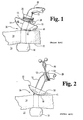
- FIG. 1 is a side elevational view of a rockable retention bolster, as disclosed in US 5,267,968 mounted onto a thin-walled catheter at a stoma site, with the catheter shown kinked from being flexed at an angle away from the bolster.
- FIG. 2 is a side elevational view of a modified prior art retention bolster with an elongated flexible collar mounted onto a thin-walled catheter at a stoma site, with the catheter shown being flexed at an angle away from the bolster without kinking and being supported by the flexible collar of the bolster.
- FIG. 3 is a side cross-sectional view of the bolster of FIG. 2 attached to a thin-walled catheter about a stoma site, with the catheter and bolster being shown in a non-flexed condition.
- FIGS. 4a-d are various views of a side exit retention bolster.
- FIG. 4a is a top plan view of the side exit retention bolster.
- FIG. 4b is a perspective view.
- FIG. 4c is a side cross-sectional view, and
- FIG. 4d is an end elevational view.
- FIG. 5 is a perspective view of the side exit retention bolster of FIGS. 4a-d being advanced along a thin-walled catheter into position for mounting thereon.
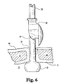
- FIG. 6 is a side elevational view of the side exit retention bolster of FIGS. 4-5, shown advanced along the catheter and ready to be pivoted thereabout into a mounted position thereon.
- FIG. 7 is a side elevational view of the side exit rockable retention bolster of FIGS. 4-6, shown pivoted into position and mounted onto thin-walled catheter to retain the catheter at a stoma site.
- FIG. 8a is a top plan view of a plastic twist lock shown in an open condition.
- FIG. 8b is a top plan view of the plastic twist-lock of FIG. 8a, shown in a twist-lock closed condition.
- FIG. 1 a prior art retention bolster 10 is shown cooperating with a percutaneous gastrostomy catheter 28 having an expanded distal tip 30 for contacting stomach wall or lining 32 of stomach 33.
- Catheter 28 is maintained clamped across epidermal layer 34 by the compressive action between retention bolster 10 and expanded distal tip 30.
- expanded distal tip 30 exerts a uniform pressure on stomach wall 32 to maintain a seal therebetween and ensure rapid healing.
- retention bolster 10 exerts an equal and opposite pressure at stoma exit site 36 necessary to maintain the compressive action.
- retention bolster 10 includes an adjustable clamp 38 about cylindrical portion 12. Clamp 38 adjusts to tighten about cylindrical portion 12 to both clamp and seal catheter 28 within bore 16. As such, retention bolster 10 is held in place contacting the epidermal surface 40.
- catheter 28 is shown rocked about the stoma exit site along convex surface 18 and epidermal surface 40 in response to movement of the catheter.
- retention bolster 10 rocks to reduce the pressure on epidermal surface 40 and to move its point of application on Lhe epidermal surface.
- retention bolster 10 Because the center of the compressive action between the retention bolster and the expanding tip is shifted away from the exit site, an overturning moment is created which acts to center the catheter once the external force is removed. As such, retention bolster 10 is self-centering. Further, by being self-centering in returning catheter 28 to its normal orientation, retention bolster 10 acts to minimize inward migration of the expanded distal Lip 30 into the stomach wall 32.
- FIG. 1 shows retention bolster 10, as disclosed in US 5,267 968, mounted onto thin-walled catheter 28 at stoma site 36, with catheter 28 shown kinked from being laterally flexed away from stoma site 36.
- cylindrical portion f12 of bolster 11 has a wall thickness of about 2.5 mm (about .100"), and a height of about 9.5 mm (about 3/8"). Owing to its relative height and thickness, cylindrical portion 12 tends to be more rigid than thin-walled catheter 28. When catheter 28 is thus flexed, as shown in FIG. 1, catheter 28 tends to kink at point 15. This tendency is removed by the following two described retention bolsters.
- FIG. 2 shows a modified prior art retention bolster 50 with an elongated flexible collar 51 that is mounted into thin-walled catheter 28 at stoma site 36.
- catheter 28 is shown being laterally flexed away from stoma site 36 without kinking, owing to the flexing support that is provided by elongated flexible collar 51.
- Flexible collar 51 is relatively thin-walled (about 0.76 mm (about .03")) and elongated (about 19 mm (about 3/4") in height), which causes collar 51 to act as a flexible support for catheter 28 during flexure to prevent catheter 28 from kinking.
- Collar 51 thus serves as a strain relief which eliminates kinking or premature stress cracking of catheter 28.
- Bolster 50 is securely held in place on catheter 28 by removable plastic twist lock 80 which is closed about collar 51 to apply a gripping pressure on catheter 28 therein.
- Annular flanges 53 and 54 serve to hold twist lock 80 in place on collar 51. Twist lock 80 can be easily disengaged if the user desires to adjust the bolster or temporarily loosen it so that the surface underneath the bolster can be cleaned.
- Bolster 50 is molded in one piece out of medical grade resilient silicone of about 50 shore A durometer, or a synthetic rubber such as Monsanto SANTOPRENE® or Shell Chemical KRATON®, which provides sufficient relative hardness so that the rocking action of bolster is maintained while being sufficiently flexibly resilient to supportively accommodate the flexing of catheter 28 therein.
- Top surface 52 is also molded flat to make for easy cleaning and nursing care.
- FIG. 3 is a side cross-sectional view of prior art bolster 50 attached to thin-walled catheter 28 about stoma site 36 in a non-stressed condition, with catheter 28 and bolster 50 being shown in an up-right non-flexed condition about stoma site 36.
- FIG. 3 also shows reduced internal diameter portion 55, which applies pressure to catheter 28 to hold bolster 50 thereonto upon the application of plastic twist lock 80 thereabout.
- FIGS. 4a-d are views of a side exit retention bolster 60.
- bolster 60 defines a curved passageway 66 which opens to a side exit 67 on upstanding portion 61.
- Side exit bolster 60 also defines a slit 69 therethrough which is oppositely disposed from side exit 67 and through which catheter 28 can be passed to advance bolster 60 along catheter 28 and into position for mounting thereon.
- bolster 60 is the same as for bolster 50, including convexly curved contacting portion 68 for rocking engagement when mounted at a stoma exit site, annular flange 64-for holding a twist lock in position, and reduced interior diameter portion 65 for applying pressure to a catheter to securely hold bolster in place thereon.
- FIG. 5 is a perspective view of side exit retention bolster 60 shown in the process of being advanced along thin-walled catheter 28 into position for mounting thereon at stoma site 36.
- slit 69 is opened to allow passage of catheter 28 therethrough.
- bolster 60 can be easily advanced along catheter 28 and into position for mounting without having to bend and "force" advance catheter 28 through the curved portion of passageway 66.
- FIG. 6 is a side elevational view, which shows the advancement of bolster 60 along catheter 28 to be completed, with bolster 60 being ready to be pivoted into mounting arrangement. Bolster 60 is then pivoted to pass catheter 28 through slit 69 and fully into curved passageway 66.
- FIG. 7 shows bolster 60 after it has been so pivoted onto catheter 28 in mounting arrangement, and with twist lock 80 applied thereon to securely fasten bolster 60 to catheter 28. While the bending of catheter 28 within passageway 66, itself, may be sufficient to securely retain catheter 28 within passageway 66, the use of twist lock 80 on bolster 60 serves to provide added security against unintended migration.
- FIGS. 4-7 provides the benefits of an upright rockable bolster, while also retaining catheter 28 at a fixed right angled orientation relative to stoma exit site.
- This configuration causes the proximal end of catheter 28 to be oriented substantially parallel with the skin surface 40, and thus establishes a very low profile.
- the total height of the bolster above the skin surface at can be constructed to be less than 23 mm (7/8 inches) high. Since catheter 28 is retained and fixed at a right angle, no kinking or repeated flexures of the catheter take place. This embodiment is especially useful when the catheter is used on active children.
- FIG. 8a is a top plan view of an injection molded twist lock 80.
- Twist lock 80 is molded in polypropylene, with ball ends 83 and 84 which are used as finger grips to twist lock or unlock the device.
- the device is semi-rigid in that it is slid over the collar portions of any embodiment of the rockable bolsters through open entrance 85 which will flex open until circular opening 88 surrounds the collar of the bolster.
- FIG. 8b shows twist lock 80 closed wherein ball ends 83 and 84 are intertwined which twist locks the device closed. Twist locking the device closed compresses opening 88 to a smaller diameter which exerts a compression force on the collar on the bolster which in turn locks the catheter in place. Once the twist lock is engaged then the bolster securely locks onto the catheter.
- twist-lock 80 can be unlocked and the bolster pulled back to permit cleaning of the catheter body exit site. The bolster is then brought back down to the skin surface and twist lock 80 is re-engaged. The twist lock can be engaged or disengaged as often as desired. This twist lock mechanism permits repeated adjustments of the bolster to take place without having to cut a permanent locking pull tie and to get a new pull tie every time adjustment is needed.
- the twist lock shown will work on all collars of all embodiments of the pivotal bolster including the embodiments shown in the original application.
Abstract
Description
FIG. 3 is a side cross-sectional view of prior art bolster 50 attached to thin-
Claims (1)
- A retention bolster (60) for retaining a tubular medical device (28) against the epidermal surface (40) at the exit site of the device (28) from the body of a patient, said bolster (60) comprising:a main body having an exterior surface portion (68) for contacting the epidermal surface (40) and an upstanding portion (61) extending therefrom; andmeans (65, 66) for securely attaching said main body to the tubular medical device (28) at the exit site of the device (28), said means (65, 66) including a passageway (66) adapted for receiving the tubular medical device (28) therethrough, said passageway (66) extending through said exterior surface portion (68) and said upstanding portion (61), and means (65) for securely retaining the tubular medical device (28) within said passageway (66); wherein said main body is attachable to the tubular medical device (28) at the exit site of the device (28) with said exterior surface portion (68) in contact with the epidermal surface (40); wherein said upstanding portion (61) defines a side opening (67), and comprises a first portion distal from said side opening (67) and a second portion including said side opening (67), said passageway (66) extends to said side opening (67), said passageway (66) has a curved portion within said main body which curves towards said side opening (67) to thereby bend and orient a tubular medical device (28) therein towards and through said side opening (67) and laterally away from the exit site of the device (28) from the body without kinking, and wherein said main body defines a slit (69) therethrough, said slit (69) being resiliently openable to allow passage of a tubular medical device (28) therethrough and into said passageway (66), wherein the advancement of said bolster (60) along the tubular medical device (28) can be facilitated by advancing the tubular medical device (28) through said slit (69) and out through said side opening (67), and wherein said bolster (60) can be pivoted into a mounting arrangement on said tubular medical device (28) by bending the tubular medical device (28) through said slit (69) and into said curved portion of said passageway (66), characterized in that the exterior surface portion (68) of the main body is convexly curved and in that the slit (69) is disposed on said main body oppositely from said side opening (67) and extends through only the first portion of the upstanding portion (61).
Applications Claiming Priority (3)
| Application Number | Priority Date | Filing Date | Title |
|---|---|---|---|
| US163843 | 1993-12-07 | ||
| US08/163,843 US5484420A (en) | 1992-07-09 | 1993-12-07 | Retention bolsters for percutaneous catheters |
| PCT/US1994/014062 WO1995015781A1 (en) | 1993-12-07 | 1994-12-07 | Retention bolsters for percutaneous catheters |
Publications (3)
| Publication Number | Publication Date |
|---|---|
| EP0732957A1 EP0732957A1 (en) | 1996-09-25 |
| EP0732957A4 EP0732957A4 (en) | 1997-11-12 |
| EP0732957B1 true EP0732957B1 (en) | 2003-04-09 |
Family
ID=22591815
Family Applications (1)
| Application Number | Title | Priority Date | Filing Date |
|---|---|---|---|
| EP95903691A Expired - Lifetime EP0732957B1 (en) | 1993-12-07 | 1994-12-07 | Retention bolsters for percutaneous catheters |
Country Status (11)
| Country | Link |
|---|---|
| US (1) | US5484420A (en) |
| EP (1) | EP0732957B1 (en) |
| JP (1) | JP3578218B2 (en) |
| AT (1) | ATE236679T1 (en) |
| AU (1) | AU691545B2 (en) |
| CA (1) | CA2177610C (en) |
| DE (1) | DE69432478T2 (en) |
| DK (1) | DK0732957T3 (en) |
| ES (1) | ES2191698T3 (en) |
| PT (1) | PT732957E (en) |
| WO (1) | WO1995015781A1 (en) |
Families Citing this family (140)
| Publication number | Priority date | Publication date | Assignee | Title |
|---|---|---|---|---|
| US7744617B2 (en) * | 1991-05-29 | 2010-06-29 | Covidien Ag | Method and inflatable chamber apparatus for separating layers of tissue |
| US5800402A (en) * | 1993-03-19 | 1998-09-01 | Venetec International, Inc. | Catheter anchoring system and method of use |
| US5738654A (en) * | 1995-03-20 | 1998-04-14 | Contimed, Inc. | Self cleansing bladder drainage device |
| US5620424A (en) * | 1995-06-26 | 1997-04-15 | Abramson; Daniel J. | Device for preventing catheter related infection |
| ES2241035T3 (en) * | 1996-01-11 | 2005-10-16 | C.R. Bard Inc. | TUBE ASSEMBLY TO ACCESS THE BODY. |
| US6077243A (en) * | 1996-01-11 | 2000-06-20 | C.R. Bard, Inc. | Retention balloon for a corporeal access tube assembly |
| US6066112A (en) * | 1996-01-11 | 2000-05-23 | Radius International Limited Partnership | Corporeal access tube assembly and method |
| US5860952A (en) * | 1996-01-11 | 1999-01-19 | C. R. Bard, Inc. | Corporeal access tube assembly and method |
| US6036673A (en) * | 1996-01-11 | 2000-03-14 | C. R. Bard, Inc. | Bolster for corporeal access tube assembly |
| EP0900069B1 (en) * | 1996-03-19 | 2005-07-20 | Sherwood Services AG | Gastrointestinal-type tube insertion or removal device |
| US5833664A (en) * | 1996-10-08 | 1998-11-10 | Seare, Jr.; William J. | Noded cuffs for transcutaneous or intrabody prosthetic devices |
| US5814021A (en) * | 1996-12-26 | 1998-09-29 | Johnson & Johnson Medical, Inc. | Adjustable securing wings |
| US6702789B1 (en) | 1997-03-11 | 2004-03-09 | Alcove Medical, Inc. | Catheter having insertion control mechanism and anti-bunching mechanism |
| US6213979B1 (en) * | 1997-05-29 | 2001-04-10 | Venetec International, Inc. | Medical line anchoring system |
| WO1999024097A1 (en) * | 1997-11-12 | 1999-05-20 | Stereotaxis, Inc. | Intracranial bolt and method of placing and using an intracranial bolt to position a medical device |
| US5895351A (en) * | 1998-02-06 | 1999-04-20 | Arthrotek Inc. | Tissue distracting cannula |
| US6100261A (en) * | 1998-05-13 | 2000-08-08 | American Cyanamid Company | Fungicidal mixtures |
| US6458109B1 (en) | 1998-08-07 | 2002-10-01 | Hill-Rom Services, Inc. | Wound treatment apparatus |
| US6045536A (en) * | 1999-02-24 | 2000-04-04 | Sherwood Services, A.G. | Securing device for a low profile gastrostomy tube |
| FR2790950B1 (en) * | 1999-03-15 | 2001-06-29 | Thierry Scheye | DEVICE FOR DELIVERING A HOLLOW VISCER ON THE SKIN |
| US6432979B1 (en) | 1999-08-12 | 2002-08-13 | American Cyanamid Company | Method of treating or inhibiting colonic polyps and colorectal cancer |
| US6824533B2 (en) * | 2000-11-29 | 2004-11-30 | Hill-Rom Services, Inc. | Wound treatment apparatus |
| US6764462B2 (en) | 2000-11-29 | 2004-07-20 | Hill-Rom Services Inc. | Wound treatment apparatus |
| US8758400B2 (en) | 2000-01-05 | 2014-06-24 | Integrated Vascular Systems, Inc. | Closure system and methods of use |
| US6572588B1 (en) * | 2000-03-10 | 2003-06-03 | Venetec International, Inc. | Medical anchoring system |
| AU2001261595A1 (en) * | 2000-05-22 | 2001-12-03 | Arthur C. Coffey | Combination sis and vacuum bandage and method |
| US6511474B1 (en) * | 2000-07-12 | 2003-01-28 | Corpak, Inc. | Bolus for non-occluding high flow enteral feeding tube |
| ATE503423T1 (en) | 2000-09-08 | 2011-04-15 | Abbott Vascular Inc | SURGICAL BRACE |
| US6855135B2 (en) | 2000-11-29 | 2005-02-15 | Hill-Rom Services, Inc. | Vacuum therapy and cleansing dressing for wounds |
| US6685681B2 (en) * | 2000-11-29 | 2004-02-03 | Hill-Rom Services, Inc. | Vacuum therapy and cleansing dressing for wounds |
| US6623510B2 (en) | 2000-12-07 | 2003-09-23 | Integrated Vascular Systems, Inc. | Closure device and methods for making and using them |
| US8690910B2 (en) | 2000-12-07 | 2014-04-08 | Integrated Vascular Systems, Inc. | Closure device and methods for making and using them |
| US6695867B2 (en) | 2002-02-21 | 2004-02-24 | Integrated Vascular Systems, Inc. | Plunger apparatus and methods for delivering a closure device |
| US20020198502A1 (en) * | 2001-06-21 | 2002-12-26 | Luke Vohsing | Medical occlusion prevention apparatus and method |
| US20030032932A1 (en) | 2001-08-09 | 2003-02-13 | Stout Cindy Kay | Feeding tube skin guard |
| KR100828483B1 (en) * | 2001-10-03 | 2008-05-13 | 스미토모 베이클라이트 가부시키가이샤 | Esophagus stoma button |
| WO2003030966A1 (en) * | 2001-10-11 | 2003-04-17 | Hill-Rom Services, Inc. | Waste container for negative pressure therapy |
| CA2468309A1 (en) * | 2001-12-26 | 2003-07-17 | Robert Petrosenko | Wound vacuum therapy dressing kit |
| WO2003057071A2 (en) | 2001-12-26 | 2003-07-17 | Hill-Rom Services, Inc. | Vacuum bandage packing |
| CA2468912A1 (en) | 2001-12-26 | 2003-07-17 | Hill-Rom Services, Inc. | Vented vacuum bandage and method |
| US7338482B2 (en) * | 2002-02-28 | 2008-03-04 | Hill-Rom Services, Inc. | External catheter access to vacuum bandage |
| US8168848B2 (en) * | 2002-04-10 | 2012-05-01 | KCI Medical Resources, Inc. | Access openings in vacuum bandage |
| WO2003095013A1 (en) * | 2002-05-13 | 2003-11-20 | Luis Blas Mompo Orti | Hemi-cannula for tracheotomy patients |
| ATE417549T1 (en) | 2002-06-04 | 2009-01-15 | Abbott Vascular Inc | SURGICAL CLAMP AND APPLICATION DEVICE FOR VESSEL WOUND CLOSURE |
| US7896856B2 (en) * | 2002-08-21 | 2011-03-01 | Robert Petrosenko | Wound packing for preventing wound closure |
| US20040054350A1 (en) * | 2002-09-17 | 2004-03-18 | Shaughnessy Michael C. | Enteral feeding unit having a reflux device and reflux method |
| CA2500376A1 (en) | 2002-10-01 | 2004-04-15 | Venetec International, Inc. | Catheter securement device |
| US20040116899A1 (en) * | 2002-12-16 | 2004-06-17 | Shaughnessy Michael C. | Bolus for non-occluding high flow enteral feeding tube |
| US8202293B2 (en) | 2003-01-30 | 2012-06-19 | Integrated Vascular Systems, Inc. | Clip applier and methods of use |
| US8398656B2 (en) | 2003-01-30 | 2013-03-19 | Integrated Vascular Systems, Inc. | Clip applier and methods of use |
| JP4411929B2 (en) * | 2003-02-28 | 2010-02-10 | 株式会社日立製作所 | Backup method, system, and program |
| US7988679B2 (en) | 2003-03-18 | 2011-08-02 | Navilyst Medical, Inc. | Pressure responsive slit valve assembly for a plurality of fluids and uses thereof |
| WO2004096115A1 (en) * | 2003-04-28 | 2004-11-11 | Sumitomo Bakelite Company Limited | Catheter kit for burrow |
| US7435236B2 (en) | 2003-06-27 | 2008-10-14 | Navilyst Medical, Inc. | Pressure actuated valve with improved biasing member |
| EP2345371B1 (en) * | 2003-08-14 | 2014-07-16 | Loma Linda University Medical Center | Vascular wound closure device |
| US7252652B2 (en) | 2003-08-29 | 2007-08-07 | Boston Scientific Scimed, Inc. | Valved catheters including high flow rate catheters |
| US20050165364A1 (en) * | 2004-01-22 | 2005-07-28 | Dimatteo Kristian | Valved catheter to bypass connector |
| US8187234B2 (en) | 2004-01-29 | 2012-05-29 | Navilyst Medical, Inc. | Pressure activated safety valve with anti-adherent coating |
| US8034035B2 (en) * | 2004-01-29 | 2011-10-11 | Navilyst Medical, Inc. | Pressure activated safety valve with high flow slit |
| US9933079B2 (en) | 2004-01-29 | 2018-04-03 | Angiodynamics, Inc. | Stacked membrane for pressure actuated valve |
| US9314608B2 (en) | 2004-01-29 | 2016-04-19 | Angiodynamics, Inc | Pressure activated safety valve with high flow slit |
| US20060030818A1 (en) * | 2004-08-09 | 2006-02-09 | Mcvey Robert D | System and method for securing a medical access device |
| WO2006060821A1 (en) * | 2004-12-03 | 2006-06-08 | Dale Medical Products, Inc. | Endotracheal tube holder |
| US7410477B2 (en) * | 2004-12-21 | 2008-08-12 | Gomez Matthew A | Supra pubic catheter |
| US7976518B2 (en) | 2005-01-13 | 2011-07-12 | Corpak Medsystems, Inc. | Tubing assembly and signal generator placement control device and method for use with catheter guidance systems |
| US7914497B2 (en) * | 2005-01-26 | 2011-03-29 | Radius International Limited Partnership | Catheter |
| US8328768B2 (en) * | 2005-02-11 | 2012-12-11 | Angiodynamics, Inc | Pressure activated safety valve with improved flow characteristics and durability |
| US8162898B1 (en) | 2005-04-18 | 2012-04-24 | Venetec International, Inc. | Venipuncture base plate assembly and method of using same |
| US7722571B2 (en) | 2005-05-23 | 2010-05-25 | Venetec International, Inc. | Medical article anchoring system |
| US20060270989A1 (en) * | 2005-05-27 | 2006-11-30 | Mcmichael Donald J | Gastric fastening system |
| US7549200B2 (en) * | 2005-05-27 | 2009-06-23 | Kimberly-Clark Worldwide, Inc. | Clamp for flexible tube |
| US8313497B2 (en) | 2005-07-01 | 2012-11-20 | Abbott Laboratories | Clip applier and methods of use |
| US9642987B2 (en) | 2005-08-31 | 2017-05-09 | C.R. Bard, Inc. | Anchoring system for a catheter |
| US20070060898A1 (en) * | 2005-09-07 | 2007-03-15 | Shaughnessy Michael C | Enteral medical treatment assembly having a safeguard against erroneous connection with an intravascular treatment system |
| US7985205B2 (en) * | 2005-09-14 | 2011-07-26 | Boston Scientific Scimed, Inc. | Medical catheter external bolster having strain relief member |
| US8052649B2 (en) | 2005-09-19 | 2011-11-08 | Venetec International, Inc. | Medical tubing securement assembly and methods of use |
| US8052648B2 (en) * | 2005-12-21 | 2011-11-08 | Venetec International, Inc. | Intravenous catheter anchoring device |
| US7879013B2 (en) | 2005-12-21 | 2011-02-01 | Venetec International, Inc. | Intravenous catheter anchoring device |
| AU2007204820B2 (en) | 2006-01-12 | 2012-09-13 | Venetec International, Inc. | Universal catheter securement device |
| US9138560B2 (en) | 2006-01-12 | 2015-09-22 | Venetec International, Inc. | Universal catheter securement device |
| US8585660B2 (en) | 2006-01-25 | 2013-11-19 | Navilyst Medical, Inc. | Valved catheter with power injection bypass |
| US8556930B2 (en) | 2006-06-28 | 2013-10-15 | Abbott Laboratories | Vessel closure device |
| US7806873B2 (en) | 2006-07-13 | 2010-10-05 | Venetec International, Inc. | Intravenous securement device with adhesively interconnected anchoring component and permeable adhesive strip |
| US20080097491A1 (en) * | 2006-08-28 | 2008-04-24 | Fred Gobel | Tissue to tissue anchoring device and method of using the same |
| US7582098B2 (en) * | 2006-08-28 | 2009-09-01 | Kimberly-Clark Wolrdwide, Inc. | Percutaneous gastrointestinal anchoring kit |
| US7607693B2 (en) * | 2006-09-18 | 2009-10-27 | Randy Chavis | Apparatus for bicycle |
| US8172749B2 (en) * | 2006-09-28 | 2012-05-08 | Cook Medical Technologies Llc | Bolster assembly |
| WO2008121311A1 (en) * | 2007-03-29 | 2008-10-09 | Boston Scientific Scimed, Inc. | Catheter assembly including coiled internal bolster |
| US9993619B2 (en) * | 2007-07-17 | 2018-06-12 | C. R. Bard, Inc. | Securement system for a medical article |
| JP5414201B2 (en) * | 2008-05-14 | 2014-02-12 | 日本コヴィディエン株式会社 | Fistula catheter and fistula catheter set |
| US9282965B2 (en) | 2008-05-16 | 2016-03-15 | Abbott Laboratories | Apparatus and methods for engaging tissue |
| US8257321B2 (en) | 2008-05-21 | 2012-09-04 | Navilyst Medical, Inc. | Pressure activated valve for high flow rate and pressure venous access applications |
| US20090318897A1 (en) * | 2008-06-20 | 2009-12-24 | Cook Critical Care Incorporated | Gastrojejunal feeding assembly |
| US20090318873A1 (en) * | 2008-06-24 | 2009-12-24 | Cook Incorporated | Medical malecot with magnets |
| US9107810B2 (en) | 2008-06-24 | 2015-08-18 | Cook Medical Technologies Llc | Gastric port system |
| US9480821B2 (en) | 2008-06-30 | 2016-11-01 | Venetec International, Inc. | Anchoring system for a medical article |
| US8398676B2 (en) | 2008-10-30 | 2013-03-19 | Abbott Vascular Inc. | Closure device |
| US9414820B2 (en) * | 2009-01-09 | 2016-08-16 | Abbott Vascular Inc. | Closure devices, systems, and methods |
| US9486191B2 (en) | 2009-01-09 | 2016-11-08 | Abbott Vascular, Inc. | Closure devices |
| US20100179589A1 (en) | 2009-01-09 | 2010-07-15 | Abbott Vascular Inc. | Rapidly eroding anchor |
| US8241314B2 (en) | 2009-01-15 | 2012-08-14 | Restoration Robotics, Inc. | Anti-popping devices and methods for hair implantation |
| US20100185234A1 (en) | 2009-01-16 | 2010-07-22 | Abbott Vascular Inc. | Closure devices, systems, and methods |
| US8337470B2 (en) * | 2009-01-28 | 2012-12-25 | Angiodynamics, Inc. | Three-way valve for power injection in vascular access devices |
| US8083721B2 (en) | 2009-01-29 | 2011-12-27 | Navilyst Medical, Inc. | Power injection valve |
| US8394067B2 (en) | 2009-05-21 | 2013-03-12 | C.R. Bard, Inc. | Medical device securement system |
| US8951232B2 (en) * | 2009-06-04 | 2015-02-10 | Covidien Lp | Gastrostomy feeding apparatus and method |
| US8007468B2 (en) | 2009-07-13 | 2011-08-30 | Navilyst Medical, Inc. | Method to secure an elastic component in a valve |
| US20110054492A1 (en) | 2009-08-26 | 2011-03-03 | Abbott Laboratories | Medical device for repairing a fistula |
| CA2776239C (en) | 2009-10-06 | 2018-06-05 | Venetec International, Inc. | Stabilizing device having a snap clamp |
| US20110087093A1 (en) * | 2009-10-09 | 2011-04-14 | Navilyst Medical, Inc. | Valve configurations for implantable medical devices |
| US10537714B2 (en) | 2009-11-11 | 2020-01-21 | Venetec International, Inc. | Stabilizing device for an extension set |
| US9132064B2 (en) | 2009-12-23 | 2015-09-15 | Avent, Inc. | Enteral feeding catheter assembly incorporating an indicator |
| AU2010336956A1 (en) * | 2009-12-30 | 2012-07-19 | Cook Medical Technologies Llc | Gastric port system |
| US8900195B2 (en) | 2010-08-24 | 2014-12-02 | Cook Medical Technologies Llc | External bolster |
| US20120078039A1 (en) | 2010-09-27 | 2012-03-29 | Kok-Ming Tai | Dilation Device for Placing Catheter Tubes |
| US8177742B1 (en) | 2010-12-23 | 2012-05-15 | Kimberly-Clark Wordwide, Inc. | Inflatable retention system for an enteral feeding device |
| US8142394B1 (en) | 2010-12-23 | 2012-03-27 | Kimberly-Clark Worldwide, Inc. | Enteral feeding catheter device with an indicator |
| WO2012145683A1 (en) | 2011-04-21 | 2012-10-26 | Venetec International, Inc. | Anchoring system |
| WO2013036772A1 (en) | 2011-09-08 | 2013-03-14 | Corpak Medsystems, Inc. | Apparatus and method used with guidance system for feeding and suctioning |
| US9332976B2 (en) | 2011-11-30 | 2016-05-10 | Abbott Cardiovascular Systems, Inc. | Tissue closure device |
| US9033930B2 (en) * | 2011-12-22 | 2015-05-19 | Avent, Inc. | Base for an enteral feeding device |
| US9895524B2 (en) | 2012-07-13 | 2018-02-20 | Angiodynamics, Inc. | Fluid bypass device for valved catheters |
| US9364209B2 (en) | 2012-12-21 | 2016-06-14 | Abbott Cardiovascular Systems, Inc. | Articulating suturing device |
| US9782328B2 (en) | 2013-03-12 | 2017-10-10 | University Of Florida Research Foundation, Inc. | Devices and methods for securing an anti-leak feeding tube for gastric and/or intestinal use |
| ES2729811T3 (en) | 2013-03-15 | 2019-11-06 | Venetec Int Inc | Clamping device that has an integrated strap and dressing |
| WO2015103094A1 (en) | 2013-12-30 | 2015-07-09 | H. Lee Moffitt Cancer Center And Research Institute, Inc. | Locking brakes for enteral feeding tube retention member |
| US9895514B2 (en) | 2014-01-27 | 2018-02-20 | Maddoc Medical Products, Inc. | Medical device securement system and method |
| US10183152B2 (en) * | 2014-12-12 | 2019-01-22 | Cook Medical Technologies Llc | Cinching peritoneal dialysis catheter |
| US10583228B2 (en) | 2015-07-28 | 2020-03-10 | J&M Shuler Medical, Inc. | Sub-atmospheric wound therapy systems and methods |
| KR102469303B1 (en) | 2016-05-13 | 2022-11-18 | 씨. 알. 바드, 인크. | CATHETER SECUREMENT DEVICE INCLUDING A GUIDING NOSE |
| US10610678B2 (en) | 2016-08-11 | 2020-04-07 | Angiodynamics, Inc. | Bi-directional, pressure-actuated medical valve with improved fluid flow control and method of using such |
| US10569069B2 (en) | 2016-12-14 | 2020-02-25 | Combat Comb, Llc | Applicator for treatments applied to animal skin |
| USD828653S1 (en) * | 2016-12-14 | 2018-09-11 | Brandon Penland | Treatment applicator |
| US11357540B2 (en) | 2018-02-16 | 2022-06-14 | Covidien Lp | Port fixation device |
| EP3956006A4 (en) | 2019-04-17 | 2023-08-16 | Bard Access Systems, Inc. | Catheter securement device including extended anchor pad and release liner clasping features |
| US11357542B2 (en) | 2019-06-21 | 2022-06-14 | Covidien Lp | Valve assembly and retainer for surgical access assembly |
| US11160917B2 (en) | 2020-01-22 | 2021-11-02 | J&M Shuler Medical Inc. | Negative pressure wound therapy barrier |
| US11627989B2 (en) | 2020-04-14 | 2023-04-18 | Covidien Lp | Protective sheath for use with a surgical instrument having an expandable body |
| US20220062592A1 (en) | 2020-08-31 | 2022-03-03 | Michael O. BONAGUIDI, JR. | Medical device stabilization system |
| US11229580B1 (en) | 2020-12-04 | 2022-01-25 | Meredith I. Sharp | Securing a percutaneous feeding device |
Family Cites Families (11)
| Publication number | Priority date | Publication date | Assignee | Title |
|---|---|---|---|---|
| US1696763A (en) * | 1927-04-06 | 1928-12-25 | Christopher E Hare | Suprapubic siphon |
| US3444861A (en) * | 1966-03-15 | 1969-05-20 | Rudolf R Schulte | Drain tube with adjusting friction lock |
| US3976080A (en) * | 1974-09-03 | 1976-08-24 | Thermo Electron Corporation | Endotracheal tube holder |
| US4185639A (en) * | 1978-03-27 | 1980-01-29 | Linder Gerald S | Adjustable stop for endotracheal tube guide |
| GB2147811A (en) * | 1983-10-11 | 1985-05-22 | Bristol Myers Co | Catheter anchoring device |
| US4645492A (en) * | 1983-10-11 | 1987-02-24 | Medical Engineering Corporation | Catheter anchoring device |
| US4834713A (en) * | 1987-10-30 | 1989-05-30 | Best Industries, Inc. | Catheter buttons |
| US4834712A (en) * | 1988-01-15 | 1989-05-30 | Corpak, Inc. | Tube fixation device |
| US5308325A (en) * | 1991-01-28 | 1994-05-03 | Corpak, Inc. | Retention balloon for percutaneous catheter |
| US5188609A (en) * | 1991-07-08 | 1993-02-23 | Bryman Medical Inc. | Swivel clip medical tube holder |
| US5267968A (en) * | 1992-07-09 | 1993-12-07 | Russo Ronald D | Retention bolster for percutaneous catheters |
-
1993
- 1993-12-07 US US08/163,843 patent/US5484420A/en not_active Expired - Lifetime
-
1994
- 1994-12-07 CA CA002177610A patent/CA2177610C/en not_active Expired - Lifetime
- 1994-12-07 ES ES95903691T patent/ES2191698T3/en not_active Expired - Lifetime
- 1994-12-07 AU AU12665/95A patent/AU691545B2/en not_active Expired
- 1994-12-07 WO PCT/US1994/014062 patent/WO1995015781A1/en active IP Right Grant
- 1994-12-07 DE DE69432478T patent/DE69432478T2/en not_active Expired - Lifetime
- 1994-12-07 JP JP51630895A patent/JP3578218B2/en not_active Expired - Fee Related
- 1994-12-07 DK DK95903691T patent/DK0732957T3/en active
- 1994-12-07 AT AT95903691T patent/ATE236679T1/en not_active IP Right Cessation
- 1994-12-07 PT PT95903691T patent/PT732957E/en unknown
- 1994-12-07 EP EP95903691A patent/EP0732957B1/en not_active Expired - Lifetime
Also Published As
| Publication number | Publication date |
|---|---|
| EP0732957A1 (en) | 1996-09-25 |
| CA2177610A1 (en) | 1995-06-15 |
| AU1266595A (en) | 1995-06-27 |
| JP3578218B2 (en) | 2004-10-20 |
| CA2177610C (en) | 2007-01-16 |
| PT732957E (en) | 2003-08-29 |
| ES2191698T3 (en) | 2003-09-16 |
| JPH09504460A (en) | 1997-05-06 |
| DE69432478D1 (en) | 2003-05-15 |
| ATE236679T1 (en) | 2003-04-15 |
| US5484420A (en) | 1996-01-16 |
| EP0732957A4 (en) | 1997-11-12 |
| DK0732957T3 (en) | 2003-07-28 |
| WO1995015781A1 (en) | 1995-06-15 |
| DE69432478T2 (en) | 2003-10-30 |
| AU691545B2 (en) | 1998-05-21 |
Similar Documents
| Publication | Publication Date | Title |
|---|---|---|
| EP0732957B1 (en) | Retention bolsters for percutaneous catheters | |
| EP0578222B1 (en) | Retention bolster for percutaneous catheters | |
| US5833666A (en) | Catheter fixation assembly | |
| CA1082554A (en) | Catheter support assembly | |
| AU697231B2 (en) | Catheter anchoring system | |
| AU2006284629B2 (en) | Anchoring system for a catheter | |
| US7731697B2 (en) | Apparatus and method for percutaneous catheter implantation and replacement | |
| US8162890B2 (en) | Catheter insertion apparatus and method of use thereof | |
| US6228064B1 (en) | Intravenous anchor system (IVFAS) | |
| JP2003526483A (en) | Mounting device for catheters, etc. | |
| US8146210B2 (en) | Support clamp for medical line | |
| US20140046265A1 (en) | Tube Holder and Method of Securing Catheters to a Patient | |
| US20080103483A1 (en) | Infusion catheter with composite tip | |
| US11628278B2 (en) | Securement device for polymer tubing and polymer coated cables | |
| US20040082916A1 (en) | Catheter support system | |
| US9492640B2 (en) | Catheter securement device and methods | |
| JP2002500538A (en) | Medical tube fixation system | |
| JPH0219170A (en) | Holder for gastral tube via nose | |
| JP2004500141A (en) | External holding device for catheter, catheter assembly and method of using the assembly | |
| US20140148778A1 (en) | Tube Anchor Assembly | |
| US11826525B2 (en) | Catheter securement device and related methods | |
| US7549200B2 (en) | Clamp for flexible tube | |
| EP0116526B1 (en) | A device for fixation of catheters and the like | |
| US6464668B1 (en) | Nasogastric tube stabilizer | |
| JPH04244170A (en) | Holding apparatus for liquid-discharging pipe |
Legal Events
| Date | Code | Title | Description |
|---|---|---|---|
| PUAI | Public reference made under article 153(3) epc to a published international application that has entered the european phase |
Free format text: ORIGINAL CODE: 0009012 |
|
| 17P | Request for examination filed |
Effective date: 19960529 |
|
| AK | Designated contracting states |
Kind code of ref document: A1 Designated state(s): AT BE CH DE DK ES FR GB GR IE IT LI LU MC NL PT SE |
|
| A4 | Supplementary search report drawn up and despatched |
Effective date: 19970908 |
|
| AK | Designated contracting states |
Kind code of ref document: A4 Designated state(s): AT BE CH DE DK ES FR GB GR IE IT LI LU MC NL PT SE |
|
| 17Q | First examination report despatched |
Effective date: 20010611 |
|
| GRAH | Despatch of communication of intention to grant a patent |
Free format text: ORIGINAL CODE: EPIDOS IGRA |
|
| GRAH | Despatch of communication of intention to grant a patent |
Free format text: ORIGINAL CODE: EPIDOS IGRA |
|
| GRAA | (expected) grant |
Free format text: ORIGINAL CODE: 0009210 |
|
| AK | Designated contracting states |
Designated state(s): AT BE CH DE DK ES FR GB GR IE IT LI LU MC NL PT SE |
|
| REG | Reference to a national code |
Ref country code: GB Ref legal event code: FG4D |
|
| REG | Reference to a national code |
Ref country code: SE Ref legal event code: TRGR Ref country code: CH Ref legal event code: NV Representative=s name: SCHMAUDER & PARTNER AG PATENTANWALTSBUERO Ref country code: CH Ref legal event code: EP |
|
| REG | Reference to a national code |
Ref country code: IE Ref legal event code: FG4D |
|
| REG | Reference to a national code |
Ref country code: GR Ref legal event code: EP Ref document number: 20030401828 Country of ref document: GR |
|
| REG | Reference to a national code |
Ref country code: DK Ref legal event code: T3 |
|
| REG | Reference to a national code |
Ref country code: ES Ref legal event code: FG2A Ref document number: 2191698 Country of ref document: ES Kind code of ref document: T3 |
|
| ET | Fr: translation filed | ||
| PLBE | No opposition filed within time limit |
Free format text: ORIGINAL CODE: 0009261 |
|
| STAA | Information on the status of an ep patent application or granted ep patent |
Free format text: STATUS: NO OPPOSITION FILED WITHIN TIME LIMIT |
|
| 26N | No opposition filed |
Effective date: 20040112 |
|
| PGFP | Annual fee paid to national office [announced via postgrant information from national office to epo] |
Ref country code: GR Payment date: 20061113 Year of fee payment: 13 |
|
| PGFP | Annual fee paid to national office [announced via postgrant information from national office to epo] |
Ref country code: MC Payment date: 20061128 Year of fee payment: 13 |
|
| PGFP | Annual fee paid to national office [announced via postgrant information from national office to epo] |
Ref country code: NL Payment date: 20061203 Year of fee payment: 13 |
|
| PGFP | Annual fee paid to national office [announced via postgrant information from national office to epo] |
Ref country code: SE Payment date: 20061206 Year of fee payment: 13 Ref country code: PT Payment date: 20061206 Year of fee payment: 13 |
|
| PGFP | Annual fee paid to national office [announced via postgrant information from national office to epo] |
Ref country code: FR Payment date: 20061208 Year of fee payment: 13 |
|
| PGFP | Annual fee paid to national office [announced via postgrant information from national office to epo] |
Ref country code: LU Payment date: 20061211 Year of fee payment: 13 |
|
| PGFP | Annual fee paid to national office [announced via postgrant information from national office to epo] |
Ref country code: CH Payment date: 20061213 Year of fee payment: 13 Ref country code: AT Payment date: 20061213 Year of fee payment: 13 |
|
| PGFP | Annual fee paid to national office [announced via postgrant information from national office to epo] |
Ref country code: DK Payment date: 20061227 Year of fee payment: 13 |
|
| PGFP | Annual fee paid to national office [announced via postgrant information from national office to epo] |
Ref country code: IT Payment date: 20061231 Year of fee payment: 13 |
|
| PGFP | Annual fee paid to national office [announced via postgrant information from national office to epo] |
Ref country code: ES Payment date: 20070122 Year of fee payment: 13 |
|
| PGFP | Annual fee paid to national office [announced via postgrant information from national office to epo] |
Ref country code: BE Payment date: 20070222 Year of fee payment: 13 |
|
| REG | Reference to a national code |
Ref country code: PT Ref legal event code: MM4A Free format text: LAPSE DUE TO NON-PAYMENT OF FEES Effective date: 20080609 |
|
| BERE | Be: lapsed |
Owner name: *RUSSO RONALD D. Effective date: 20071231 |
|
| PG25 | Lapsed in a contracting state [announced via postgrant information from national office to epo] |
Ref country code: MC Free format text: LAPSE BECAUSE OF NON-PAYMENT OF DUE FEES Effective date: 20071231 |
|
| REG | Reference to a national code |
Ref country code: CH Ref legal event code: PL |
|
| REG | Reference to a national code |
Ref country code: DK Ref legal event code: EBP |
|
| EUG | Se: european patent has lapsed | ||
| PG25 | Lapsed in a contracting state [announced via postgrant information from national office to epo] |
Ref country code: AT Free format text: LAPSE BECAUSE OF NON-PAYMENT OF DUE FEES Effective date: 20071207 |
|
| NLV4 | Nl: lapsed or anulled due to non-payment of the annual fee |
Effective date: 20080701 |
|
| PG25 | Lapsed in a contracting state [announced via postgrant information from national office to epo] |
Ref country code: PT Free format text: LAPSE BECAUSE OF NON-PAYMENT OF DUE FEES Effective date: 20080609 Ref country code: BE Free format text: LAPSE BECAUSE OF NON-PAYMENT OF DUE FEES Effective date: 20071231 |
|
| PG25 | Lapsed in a contracting state [announced via postgrant information from national office to epo] |
Ref country code: SE Free format text: LAPSE BECAUSE OF NON-PAYMENT OF DUE FEES Effective date: 20071208 Ref country code: LI Free format text: LAPSE BECAUSE OF NON-PAYMENT OF DUE FEES Effective date: 20071231 Ref country code: CH Free format text: LAPSE BECAUSE OF NON-PAYMENT OF DUE FEES Effective date: 20071231 |
|
| REG | Reference to a national code |
Ref country code: FR Ref legal event code: ST Effective date: 20081020 |
|
| PG25 | Lapsed in a contracting state [announced via postgrant information from national office to epo] |
Ref country code: NL Free format text: LAPSE BECAUSE OF NON-PAYMENT OF DUE FEES Effective date: 20080701 |
|
| PG25 | Lapsed in a contracting state [announced via postgrant information from national office to epo] |
Ref country code: DK Free format text: LAPSE BECAUSE OF NON-PAYMENT OF DUE FEES Effective date: 20080102 |
|
| REG | Reference to a national code |
Ref country code: ES Ref legal event code: FD2A Effective date: 20071210 |
|
| PG25 | Lapsed in a contracting state [announced via postgrant information from national office to epo] |
Ref country code: FR Free format text: LAPSE BECAUSE OF NON-PAYMENT OF DUE FEES Effective date: 20071231 Ref country code: ES Free format text: LAPSE BECAUSE OF NON-PAYMENT OF DUE FEES Effective date: 20071210 |
|
| PG25 | Lapsed in a contracting state [announced via postgrant information from national office to epo] |
Ref country code: GR Free format text: LAPSE BECAUSE OF NON-PAYMENT OF DUE FEES Effective date: 20080702 |
|
| PG25 | Lapsed in a contracting state [announced via postgrant information from national office to epo] |
Ref country code: LU Free format text: LAPSE BECAUSE OF NON-PAYMENT OF DUE FEES Effective date: 20071207 Ref country code: IT Free format text: LAPSE BECAUSE OF NON-PAYMENT OF DUE FEES Effective date: 20071207 |
|
| PGFP | Annual fee paid to national office [announced via postgrant information from national office to epo] |
Ref country code: IE Payment date: 20131210 Year of fee payment: 20 Ref country code: DE Payment date: 20131204 Year of fee payment: 20 Ref country code: GB Payment date: 20131204 Year of fee payment: 20 |
|
| REG | Reference to a national code |
Ref country code: DE Ref legal event code: R071 Ref document number: 69432478 Country of ref document: DE |
|
| REG | Reference to a national code |
Ref country code: DE Ref legal event code: R071 Ref document number: 69432478 Country of ref document: DE |
|
| REG | Reference to a national code |
Ref country code: GB Ref legal event code: PE20 Expiry date: 20141206 |
|
| REG | Reference to a national code |
Ref country code: IE Ref legal event code: MK9A |
|
| PG25 | Lapsed in a contracting state [announced via postgrant information from national office to epo] |
Ref country code: GB Free format text: LAPSE BECAUSE OF EXPIRATION OF PROTECTION Effective date: 20141206 |
|
| PG25 | Lapsed in a contracting state [announced via postgrant information from national office to epo] |
Ref country code: IE Free format text: LAPSE BECAUSE OF EXPIRATION OF PROTECTION Effective date: 20141207 |