EP0732600A2 - Active impulse magnetometer - Google Patents
Active impulse magnetometer Download PDFInfo
- Publication number
- EP0732600A2 EP0732600A2 EP96301239A EP96301239A EP0732600A2 EP 0732600 A2 EP0732600 A2 EP 0732600A2 EP 96301239 A EP96301239 A EP 96301239A EP 96301239 A EP96301239 A EP 96301239A EP 0732600 A2 EP0732600 A2 EP 0732600A2
- Authority
- EP
- European Patent Office
- Prior art keywords
- magnetic
- further characterized
- vessel
- magnetometer system
- magnetometer
- Prior art date
- Legal status (The legal status is an assumption and is not a legal conclusion. Google has not performed a legal analysis and makes no representation as to the accuracy of the status listed.)
- Granted
Links
Images


Classifications
-
- G—PHYSICS
- G01—MEASURING; TESTING
- G01V—GEOPHYSICS; GRAVITATIONAL MEASUREMENTS; DETECTING MASSES OR OBJECTS; TAGS
- G01V3/00—Electric or magnetic prospecting or detecting; Measuring magnetic field characteristics of the earth, e.g. declination, deviation
- G01V3/08—Electric or magnetic prospecting or detecting; Measuring magnetic field characteristics of the earth, e.g. declination, deviation operating with magnetic or electric fields produced or modified by objects or geological structures or by detecting devices
Definitions
- the present invention relates to systems for detecting metal objects such as mines in shallow salt water, and more particularly to a detection system employing a magnetic impulse waveform generated by a magnetic field transmitter which is received by a separate receiver element.
- a fixed frequency oscillator is used as the transmitter.
- the transmitter develops an "electro-magnetic field" in some form of a coil.
- a similar coil arrangement is used at the receiver.
- the receiver is designed so that the direct path energy is canceled in the receiver.
- the receiver output is sensitive only to disturbances in the "electro magnetic field” near the coil. (Frequently these changes are just capacitance or inductance change effects on a tuned circuit.)
- Metal targets are detected as an "unbalanced" condition in the receiver.
- the coils are moved around over the suspected target area.
- the metal object is located at the point where the maximum receiver output is achieved, directly over the mine or other metal object.
- Sonar systems have also been tried for mine detection in shallow salt water. However, sonar has a very difficult time operating in shallow water and near the surf. Sonar also has a difficult time with mine size targets on the bottom or which are buried.
- Impulse radars Ultra Wide Band
- 1 to 10 nanosecond impulse radars work quite well in dry soil and even in fresh water or snow.
- salt water the attenuation of greater than 60 db per foot is a prohibitive signal loss factor.
- Magnetometers have been very successful in the detection of slight variations in the earth's static magnetic field. These devices are used for submarine detection at depths of more than 500 feet.
- the Navy has long used VLF communications systems which have negligible salt water signal attenuations at 10 KHz to 40 KHz carrier frequencies for communications with submarines below the sea and around the world.
- An active impulse magnetometer for detecting metal objects such as mines in shallow water.
- the magnetometer comprises a magnetic transmitter element secured on a movable vehicle, and a pulse generator for driving said transmitter element to transmit first and second magnetic pulses of opposite polarity.
- a magnetic receiver element is secured on the vehicle in a spaced relationship relative to the transmitter element.
- the magnetometer further includes means for measuring an impulse response to the magnetic pulses, comprising means responsive to magnetic signals received at the receiver element in response to the transmitted magnetic pulses for performing a fast Fourier transformation of the received signals.
- the magnetometer includes means for providing a vehicle location signal indicative of a present location of the vehicle, and signal processor responsive to the transformed received signals and to the vehicle location signal to locate metal targets causing disturbances in the magnetic impulse response.
- the movable vehicle is a water vessel
- the magnetic transmitter element is mounted along one of the port or starboard sides of the vessel
- the magnetic receiver element is mounted along the other of the port or starboard sides.
- a controller for controlling for controlling the operation of the pulse generator and measuring means.
- the controller comprising means for blanking operation of the measuring means during the first magnetic pulse transmission, and for enabling operation of the measuring means during transmission of the second pulse.
- This invention is an active impulse magnetometer (AIM). It uses a magnetic impulse wave form generated by a magnetic field transmitter which is received by a separate bi-static "active magnetometer” receiver element. This unique waveform has been found to penetrate through aluminum, steel and other metals with little or no attenuation. Tests have demonstrated that a low frequency magnetic impulse has very little loss through ocean salt water. Tests further show that metal targets which are in the sensor field anywhere around the magnetic field generator can be detected as the cause of variations in the received field.
- AIM active impulse magnetometer
- the AIM system is well suited for the detection of metal mines in ocean water. Other applications such as enhanced submarine detection and underwater communications are contemplated.
- FIGS. 1 and 2 show an embodiment of the sensor 50 mounted on a vessel 20 such as a ship or boat.
- the sensor system 50 includes a transmitter transducer element 52 and a receiver transducer element 54 mounted on opposite sides of the vessel 20.
- the objective of the sensor system 50 is to detect the presence and location of a submerged metal target 80.
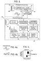
- FIG. 3 illustrates a schematic block diagram of the sensor system 50.
- a system controller 60 controls the operation of the system.
- a transmit section 56 comprises a pulse generator 62, a current switcher 64 and the transmit propagator element 52.
- the controller 60 triggers the pulse generator to generate a two pulse waveform, as shown in FIG. 8.
- the current switcher 64 operates to invert the polarity of the second pulse, to create the transmit waveform shown in FIG. 4A.
- the transmit waveform is applied to the transmit propagation element 52, which comprises coil 52A wound about a core 52B.
- This unique bipolar magnetic impulse waveform is preferred over more conventional mono-polar waveforms because the rate of change of the magnetic field from a positive field to a negative field provides improved receiver sensitivity, better time reference as well as better control of the transmitted magnetic field waveform.
- the receiver section 58 of the sensor 50 includes the receiver element 54, a preamplifier 70 for applying a first amplification level to the signals received by the receiver transducer element 54.
- the output from the preamplifier is passed through a programmable attenuator 72, whose attenuation level is set by the controller 60 to operate the receiver in an effective desired on/off state.
- the receiver 58 When the attenuator 72 is controlled to provide maximum attenuation to the received, pre-amplified signal, the receiver 58 is effectively "off”; with a minimum attenuation level set in the attenuator, the receiver is effectively "on.”
- the controller 60 provides a blanking signal to the attenuator 72 to put the receiver in an "off” state during transmission of a positive magnetic pulse, and removes the blanking signal to put the receiver in an on state during transmission of the negative magnetic pulse.
- the output of the attenuator 72 is passed to an amplifier/filter section 74, where the received signal is amplified further and filtered. This filtering is preferred to reduce 50 Hz or 60 Hz and harmonics thereof, and/or other primary power line frequencies which are often found in harbors and near shore.
- An analog-to-digital convertor (ADC) 76 converts the amplified, filtered signal into a digital value. In the preferred system there are 1024 digital samples over a 100 millisecond period of time. The digitized signal is applied to the Fast Fourier Transform device 78, which produces a frequency spectrum with 10 Hz resolution over a frequency range of 10 Hz to 10.24 kHz.
- the transformed signal is processed by the digital signal processor (DSP) 80, which also knows the vessel location as a result of a vehicle location log 82.
- the DSP 80 controls a falling raster display 84 to display the frequency domain signals versus the vehicle location, as shown in FIG. 5.
- the transmitter section 56 of the sensor system 50 provides an impulse magnetic field waveform.
- a carrier signal is usually employed, upon which "modulation" is placed which contains the information to be transmitted. It is equally reasonable to transmit the information by a "coded sequence" of impulses which are one cycle of the center frequency of the radio band selected for the data transmission. Multiple single impulses would form a data stream which could be transmitted directly, without a carrier, from one location to another. This form of communication is referred to as impulse data transmission.
- FIG. 6 illustrates a schematic diagram of an exemplary embodiment of the current switcher 64 comprising the transmitter.
- the current switcher 64 includes two pairs of switches S11, S12, S21 and S22, each of which is controlled by a switch control gate comprising the pulse generator 62.
- Two resistors 64A and 64B are connected in parallel to a voltage source at +V.
- Switches S11 and S12 are connected in series from node 64C to ground.
- Switches S21 and S22 are connected in series from node 64D to ground.
- Capacitors 64E and 64F are connected from respective nodes 64C and 64D to ground, in parallel with the respective switch pairs.
- Node 64G and 64H are connected to the transmission line 64I. The other end of the transmission line 64I is connected to the transmitter coil 64J.
- the switch pairs provide a means of applying a voltage of selectable polarity to the transmitter coil 64J.
- Each capacitor 64E and 64F will be charged to a voltage V.
- Closing switches S11 and S22 while leaving open switches S12 and S21 will apply a voltage pulse of a first polarity to the transmitter coil 64J.
- Closing switches S21 and S12 while leaving open switches S11 and S22 will apply a voltage pulse of a second polarity to the transmitter coil 64J.
- FIG. 7 is a schematic diagram of an exemplary pulse generator 62.
- the switches S11, S12, S21 and S22 of the current switcher 64 are controlled by a pair of switch control gates 62A and 62B comprising the pulse generator 62.
- a trigger generator 62C is clocked by a clock signal, and receives a code signal from the system controller 60. This code signal operates the trigger generator 62C to initiate trigger pulses +P and -P.
- the pulse waveform is shown in FIG. 8.
- the pulse +P is active, to close switches S11 and S22, and the pulse -P is not active, leaving open switches S12 and S21.
- the pulse -P is active, to close switches S21 and S12, and the pulse +P is not active, leaving open switches S11 and S22.
- the output power of the impulse switch is primarily dependent upon the maximum voltage allowed for switching and on the impedance of the devices S11, S12, S21 and S22 being switched. The faster the switch is toggled from ON to OFF the smaller the amount of heat that must be dissipated from the device during switching. Fast switching times faster than 100 microseconds are preferred to create a good harmonic content in the waveform.
- the amplitude and phase of each of the harmonic spectral lines will be determined by the net sum of all of the energy received at the receiving element 54, from all fixed metal objects near the system.
- the net sum of the received energy will change based upon changes in the fields caused by other metal objects when encountered.
- the sensor will indicate changes at any location around the craft.
- a computerized histogram of the relative amplitude and phase disturbances (or differences) will localize the location of the metal device at right angles to the path of travel. This is in effect a "spherical ring" around the platform of maximum sensitivity.
- audio output signals could be provided to a swimmer using earphones or some other form of audio transducer. Indicator lights could also be used when desired.
- the AIM system can be maneuvered along the beach 300 to 500 feet from the beach on the first pass.
- the data from this pass is recorded in a computer and displayed as an "intensity varying strip chart" on the display screen.
- the boat would then move in closer by 100 feet or so and make another pass. This would continue until the boat was as close as safely possible.
- the mines and any other metal objects would show up as changes in intensity on the display screen at the point in the path where the sensor was the closest to the mines. This same process can be done covertly using a submerged mini-sub or remotely controlled vehicle.
- the magnetic propagators are mounted on each side of a small boat below the water line.
- each element is approximately 1.5 to 2 inches in diameter.
- Each element is housed in a PVC plastic tube (or equivalent) which is sealed.
- the transmitter propagator elements and the receiver elements are 6 to 8 feet long for target ranges of 20 to 40 feet. It is preferred to have a spacing of 6 to 8 feet between the propagator and receiver elements.
- the mines in the shallow water areas are typically in metal containers with pressure sensors, magnetic sensors or trip wire activators. They may be on the bottom or buried in the sand. The typical water depths of up to 40 feet are expected.
- a sensor which detects these mines should be capable of working while submerged with distances between the surface and the bottom of 5 feet to as much as 50 feet. Preferably, there is a method of "marking" the mine location once they have been detected to that they can be avoided or destroyed. It would also be highly desirable to identify mines located in the surf and on the beach.
- GPS global positioning system
- An active impulse magnetometer in accordance with the invention provides efficient detection of metal mines in shallow sea water. Some of the characteristics of the system are:
Abstract
Description
- The present invention relates to systems for detecting metal objects such as mines in shallow salt water, and more particularly to a detection system employing a magnetic impulse waveform generated by a magnetic field transmitter which is received by a separate receiver element.
- The detection and identification of objects at relatively close ranges requires either high range resolution or some other form of "contrast" which will allow the discrimination between targets and clutter to be made. This contrast must be sufficiently unique to allow "automatic" recognition of the contrast and thus "detection" of the desired targets (mines). Clutter, on the other hand, is all of the other fluctuations of the signal which may have some characteristics which appear as a target of interest but which are not. It the separation of "targets" from "clutter" which limits the performance of all electronic detection systems.
- In the classical "balanced coil" techniques used for metal detection (like those found in airports), a fixed frequency oscillator is used as the transmitter. The transmitter develops an "electro-magnetic field" in some form of a coil. A similar coil arrangement is used at the receiver. The receiver is designed so that the direct path energy is canceled in the receiver. The receiver output is sensitive only to disturbances in the "electro magnetic field" near the coil. (Frequently these changes are just capacitance or inductance change effects on a tuned circuit.)
- Metal targets are detected as an "unbalanced" condition in the receiver. The closer the field coils are to a metal object the greater the unbalance condition. The coils are moved around over the suspected target area. The metal object is located at the point where the maximum receiver output is achieved, directly over the mine or other metal object.
- These "classical" balanced coil systems work quite well when the sensor is directly over the metal object at close range. However, they lose performance rapidly as the distance between the sensor and target increases. These systems also suffer from high levels of attenuation in the salt water because of the carrier frequencies used by the oscillators.
- Conventional "hand held" metal mine detection devices have provided a degree of effectiveness for the detection of shallow metal mines on land. However, such devices are typically limited to a few feet range, directly above the metal object being detected. They have been of little or no value in salt water.
- Sonar systems have also been tried for mine detection in shallow salt water. However, sonar has a very difficult time operating in shallow water and near the surf. Sonar also has a difficult time with mine size targets on the bottom or which are buried.
- Impulse radars (Ultra Wide Band) have been successfully used for detection of both metal and non-metal buried mines under some conditions. These 1 to 10 nanosecond impulse radars work quite well in dry soil and even in fresh water or snow. However, with salt water the attenuation of greater than 60 db per foot is a prohibitive signal loss factor.
- Devices known as magnetometers have been very successful in the detection of slight variations in the earth's static magnetic field. These devices are used for submarine detection at depths of more than 500 feet.
- The Navy has long used VLF communications systems which have negligible salt water signal attenuations at 10 KHz to 40 KHz carrier frequencies for communications with submarines below the sea and around the world.
- An active impulse magnetometer is described for detecting metal objects such as mines in shallow water. The magnetometer comprises a magnetic transmitter element secured on a movable vehicle, and a pulse generator for driving said transmitter element to transmit first and second magnetic pulses of opposite polarity. A magnetic receiver element is secured on the vehicle in a spaced relationship relative to the transmitter element. The magnetometer further includes means for measuring an impulse response to the magnetic pulses, comprising means responsive to magnetic signals received at the receiver element in response to the transmitted magnetic pulses for performing a fast Fourier transformation of the received signals. The magnetometer includes means for providing a vehicle location signal indicative of a present location of the vehicle, and signal processor responsive to the transformed received signals and to the vehicle location signal to locate metal targets causing disturbances in the magnetic impulse response.
- In a preferred embodiment, the movable vehicle is a water vessel, and the magnetic transmitter element is mounted along one of the port or starboard sides of the vessel, and the magnetic receiver element is mounted along the other of the port or starboard sides.
- According to one aspect of the invention a controller for controlling is provided for controlling the operation of the pulse generator and measuring means. The controller comprising means for blanking operation of the measuring means during the first magnetic pulse transmission, and for enabling operation of the measuring means during transmission of the second pulse.
- These and other features and advantages of the present invention will become more apparent from the following detailed description of an exemplary embodiment thereof, as illustrated in the accompanying drawings, in which:
- FIGS. 1 and 2 are top and side views, respectively, of a vessel fitted with a mine detection system in accordance with the invention.
- FIG. 3 is a schematic block diagram of the mine detection system of FIG. 1.
- FIG. 4A shows an exemplary transmit magnetic pulse waveform generated by the system of FIG. 3, and FIG. 4B shows an exemplary corresponding receive waveform.
- FIG. 5 shows an exemplary raster display comprising the system of
Claim 1. - FIG. 6 is a schematic diagram of a current switcher circuit used in the system of FIG. 3.
- FIG. 7 shows a schematic diagram of an exemplary implementation of a pulse generator comprising the system of Claim 3.
- FIG. 8 shows a switch drive waveform for the current switcher of FIG. 6.
- This invention is an active impulse magnetometer (AIM). It uses a magnetic impulse wave form generated by a magnetic field transmitter which is received by a separate bi-static "active magnetometer" receiver element. This unique waveform has been found to penetrate through aluminum, steel and other metals with little or no attenuation. Tests have demonstrated that a low frequency magnetic impulse has very little loss through ocean salt water. Tests further show that metal targets which are in the sensor field anywhere around the magnetic field generator can be detected as the cause of variations in the received field.
- The AIM system is well suited for the detection of metal mines in ocean water. Other applications such as enhanced submarine detection and underwater communications are contemplated.
- In a fully operational configuration the complete AIM sensor can be mounted on a "mini-sub" or small remote controlled vehicle. It might be lowered over the side or fixed mounted on a small patrol craft. FIGS. 1 and 2 show an embodiment of the
sensor 50 mounted on avessel 20 such as a ship or boat. Thesensor system 50 includes atransmitter transducer element 52 and areceiver transducer element 54 mounted on opposite sides of thevessel 20. The objective of thesensor system 50 is to detect the presence and location of a submergedmetal target 80. - FIG. 3 illustrates a schematic block diagram of the
sensor system 50. Asystem controller 60 controls the operation of the system. A transmitsection 56 comprises apulse generator 62, acurrent switcher 64 and the transmitpropagator element 52. Thecontroller 60 triggers the pulse generator to generate a two pulse waveform, as shown in FIG. 8. Thecurrent switcher 64 operates to invert the polarity of the second pulse, to create the transmit waveform shown in FIG. 4A. The transmit waveform is applied to the transmitpropagation element 52, which comprises coil 52A wound about a core 52B. This unique bipolar magnetic impulse waveform is preferred over more conventional mono-polar waveforms because the rate of change of the magnetic field from a positive field to a negative field provides improved receiver sensitivity, better time reference as well as better control of the transmitted magnetic field waveform. - The
receiver section 58 of thesensor 50 includes thereceiver element 54, apreamplifier 70 for applying a first amplification level to the signals received by thereceiver transducer element 54. The output from the preamplifier is passed through aprogrammable attenuator 72, whose attenuation level is set by thecontroller 60 to operate the receiver in an effective desired on/off state. When theattenuator 72 is controlled to provide maximum attenuation to the received, pre-amplified signal, thereceiver 58 is effectively "off"; with a minimum attenuation level set in the attenuator, the receiver is effectively "on." Thecontroller 60 provides a blanking signal to theattenuator 72 to put the receiver in an "off" state during transmission of a positive magnetic pulse, and removes the blanking signal to put the receiver in an on state during transmission of the negative magnetic pulse. - The output of the
attenuator 72 is passed to an amplifier/filter section 74, where the received signal is amplified further and filtered. This filtering is preferred to reduce 50 Hz or 60 Hz and harmonics thereof, and/or other primary power line frequencies which are often found in harbors and near shore. An analog-to-digital convertor (ADC) 76 converts the amplified, filtered signal into a digital value. In the preferred system there are 1024 digital samples over a 100 millisecond period of time. The digitized signal is applied to the FastFourier Transform device 78, which produces a frequency spectrum with 10 Hz resolution over a frequency range of 10 Hz to 10.24 kHz. The transformed signal is processed by the digital signal processor (DSP) 80, which also knows the vessel location as a result of avehicle location log 82. TheDSP 80 controls a fallingraster display 84 to display the frequency domain signals versus the vehicle location, as shown in FIG. 5. - The
transmitter section 56 of thesensor system 50 provides an impulse magnetic field waveform. In order to transmit information from one location to another, a carrier signal is usually employed, upon which "modulation" is placed which contains the information to be transmitted. It is equally reasonable to transmit the information by a "coded sequence" of impulses which are one cycle of the center frequency of the radio band selected for the data transmission. Multiple single impulses would form a data stream which could be transmitted directly, without a carrier, from one location to another. This form of communication is referred to as impulse data transmission. - FIG. 6 illustrates a schematic diagram of an exemplary embodiment of the
current switcher 64 comprising the transmitter. Thecurrent switcher 64 includes two pairs of switches S11, S12, S21 and S22, each of which is controlled by a switch control gate comprising thepulse generator 62. Tworesistors node 64C to ground. Switches S21 and S22 are connected in series fromnode 64D to ground.Capacitors respective nodes Node transmitter coil 64J. - It will be apparent that the switch pairs provide a means of applying a voltage of selectable polarity to the
transmitter coil 64J. Eachcapacitor transmitter coil 64J. Closing switches S21 and S12 while leaving open switches S11 and S22 will apply a voltage pulse of a second polarity to thetransmitter coil 64J. - FIG. 7 is a schematic diagram of an
exemplary pulse generator 62. The switches S11, S12, S21 and S22 of thecurrent switcher 64 are controlled by a pair ofswitch control gates pulse generator 62. Atrigger generator 62C is clocked by a clock signal, and receives a code signal from thesystem controller 60. This code signal operates thetrigger generator 62C to initiate trigger pulses +P and -P. The pulse waveform is shown in FIG. 8. During the first half of the trigger duty cycle, the pulse +P is active, to close switches S11 and S22, and the pulse -P is not active, leaving open switches S12 and S21. During the second half of the trigger duty cycle, the pulse -P is active, to close switches S21 and S12, and the pulse +P is not active, leaving open switches S11 and S22. - The output power of the impulse switch is primarily dependent upon the maximum voltage allowed for switching and on the impedance of the devices S11, S12, S21 and S22 being switched. The faster the switch is toggled from ON to OFF the smaller the amount of heat that must be dissipated from the device during switching. Fast switching times faster than 100 microseconds are preferred to create a good harmonic content in the waveform.
- The switches can be implemented by FET switch devices. Commercially available FET devices can switch up to 2000 volts. Because peak power is determined by E2/R, the lower the total resistance of the switch devices (including the load) the greater the power level that can be generated. If, for example, the load impedance was 10 ohms, then the total peak power switched would be (2000x2000)/10 = 400,000 watts.
- At the FFT output, the amplitude and phase of each of the harmonic spectral lines will be determined by the net sum of all of the energy received at the receiving
element 54, from all fixed metal objects near the system. When the platform is moved through the water, the net sum of the received energy will change based upon changes in the fields caused by other metal objects when encountered. Because the magnetic lines of force are curved, the sensor will indicate changes at any location around the craft. A computerized histogram of the relative amplitude and phase disturbances (or differences) will localize the location of the metal device at right angles to the path of travel. This is in effect a "spherical ring" around the platform of maximum sensitivity. - Because different types of metal have different responses to magnetic impulse fields, to some degree the type of targets can be identified to aid in clutter reduction. Such thing as large metal pipes buried under the beach will be indicated, but the response characteristics will be much different than the much smaller metal mines.
- The output from the sensor will depend on the specific user's needs. In an operational system, audio output signals could be provided to a swimmer using earphones or some other form of audio transducer. Indicator lights could also be used when desired.
- In the side looking search mode, the AIM system can be maneuvered along the beach 300 to 500 feet from the beach on the first pass. The data from this pass is recorded in a computer and displayed as an "intensity varying strip chart" on the display screen. The boat would then move in closer by 100 feet or so and make another pass. This would continue until the boat was as close as safely possible. The mines and any other metal objects would show up as changes in intensity on the display screen at the point in the path where the sensor was the closest to the mines. This same process can be done covertly using a submerged mini-sub or remotely controlled vehicle.
- In the forward looking search mode, swimmers follow behind the AIM system. Any metal objects detected ahead of the sensor would cause an alarm. The forward looking mode is possible because the lines of magnetic force curve around the magnet rather than going in straight line as radar or sonar waves do.
- In an exemplary system, the magnetic propagators (coils with cores) are mounted on each side of a small boat below the water line. In an exemplary embodiment, each element is approximately 1.5 to 2 inches in diameter. Each element is housed in a PVC plastic tube (or equivalent) which is sealed. The transmitter propagator elements and the receiver elements are 6 to 8 feet long for target ranges of 20 to 40 feet. It is preferred to have a spacing of 6 to 8 feet between the propagator and receiver elements.
- The mines in the shallow water areas are typically in metal containers with pressure sensors, magnetic sensors or trip wire activators. They may be on the bottom or buried in the sand. The typical water depths of up to 40 feet are expected.
- A sensor which detects these mines should be capable of working while submerged with distances between the surface and the bottom of 5 feet to as much as 50 feet. Preferably, there is a method of "marking" the mine location once they have been detected to that they can be avoided or destroyed. It would also be highly desirable to identify mines located in the surf and on the beach. A global positioning system (GPS) device could provide a reasonable method of mine location identification.
- An active impulse magnetometer in accordance with the invention provides efficient detection of metal mines in shallow sea water. Some of the characteristics of the system are:
- 1. A non-fluctuation or stationary "DC Magnetic Field" (for example, the earth's magnetic field) suffers little or no attenuation by salt water or even metal objects.
- 2. If a magnetic field is "amplitude modulated" with information, that information may also be propagated through metal or salt water. There will be little or no attenuation other than the normal (1/R3) one way loss. The magnetic field become the information carrier.
The range loss (R) is strongly affected by the relative distance between the magnetic poles of the propagator elements. As the distance between the magnetic poles of a single magnet becomes greater, so does the relative magnetic field at a given distance become greater. Thus, the increased distance between the magnetic poles produces a "gain" effect similar to the "gain" effect experienced in electro magnetic radiator where the antenna area is increased to increase the gain. The length of the path or area covered by these lines of force is dependent upon the distance between the two dipoles (N-S). Likewise, the "field strength" is also related to the dipole separation. The earth is a good example of widely spaced dipoles with lines of magnetic force extending thousand of miles away from the earth's surface. - 3. As the magnetic field modulating frequency is increased above 10 KHz, some information loss is experienced in salt water and through some metals. As modulation frequencies increases above 100 KHz, the attenuation becomes significant but predictable. This is true for each different type of media being penetrated.
- 4. Magnetic lines of force always curve around the magnetic dipoles (North pole - South Pole) of any magnet. These lines form well defined curves as they leave the North Pole and proceed to the South Pole. Thus, these lines of force can be influenced by any metal objects which are in the curved path.
- 5. When the magnetic field receiver element (similar to the transmitter propagator element) is placed in an area of the lines of force (frequently parallel to the other element) the receiver can detect any modulation which is placed on the originating magnetic field. The greater the distance between the propagator dipoles (propagator length) the greater the distance would be between the transmitting and receiving elements for a give transmitter power level.
- 6. A magnetic impulse contains all frequencies. Thus, a magnetic impulse which lasts for 10 milliseconds contains low frequency components (100 Hz) which can be used to establish a DC magnetic field for a short period to time. All frequencies above 100 Hz will also be contained in the waveform.
- 7. The waveform received by the receiving element is a modified version of the transmitted waveform. A number of factors will modify this received waveform, one of which is the presence of any metallic objects within the magnetic field envelope.
- 8. A Fast Fourier Transform (FFT) device is used to establish the frequency domain characteristics of the received impulse response. This FFT is extremely sensitive to slight changes of both amplitude and phase in the overall received waveform.
- It is understood that the above-described embodiments are merely illustrative of the possible specific embodiments which may represent principles of the present invention. Other arrangements may readily be devised in accordance with these principles by those skilled in the art without departing from the scope and spirit of the invention.
Claims (9)
- An active impulse magnetometer system (50), characterized by:a magnetic transmitter element (52);a pulse generator (62) for driving said transmitter element to transmit first and second magnetic pulses of opposite polarity;a magnetic receiver element (54);apparatus for measuring an impulse response to said magnetic pulses, said apparatus comprising an FFT transformer (78) responsive to magnetic signals received at said receiver element in response to said transmitted magnetic pulses for performing a fast Fourier transformation of said received signals; andsignal processor (80) responsive to said transformed received signals to indicate the presence of metal objects causing disturbances in said magnetic impulse response.
- A magnetometer system according to Claim 1, further characterized in that said transmitter element (52) comprises a coil having a ferrous core.
- A magnetometer system according to Claim 1 or Claim 2, further characterized in that said receiver element (54) comprises a coil having a ferrous core.
- A magnetometer system according to any preceding claim, further characterized in that said transmitter element (52) and said receiver element (54) are mounted on a movable vehicle (20).
- A magnetometer system according to Claim 4, further characterized in that movable vehicle (20) is a water vessel, and said magnetic transmitter element (52) is mounted along one of the port or starboard sides of said vessel (20), and said magnetic receiver element (54) is mounted along the other of said port or starboard sides.
- A magnetometer system according to any preceding claim further characterized by a controller (60) for controlling the operation of said pulse generator (62) and said FFT transformer (78), said controller comprising apparatus for blanking operation of said measuring apparatus during said first magnetic pulse transmission, and for enabling operation of said measuring apparatus during transmission of said second pulse.
- A magnetometer system according to Claim 4 or Claim 5, further characterized by a vehicle location log device (82) for providing a vehicle location signal indicative of a present location of said vehicle, and in that said signal processor (80) is responsive to said transformed received signals and to said vehicle location signal to locate said metal targets.
- A magnetometer system according to any preceding claim, further characterized in that said system is a mine detector for detection of sea mines, and in that the magnetic transmitter element (52) is secured on a movable sea-going vessel, the magnetic receiver element (54) is secured on said vessel in a spaced relationship relative the transmitter element and the signal processor (80) is responsive to said transformed received signals to detect mines causing disturbances in said magnetic impulse response.
- A magnetometer system according to Claim 8, further characterized by a vehicle location log device (82) for providing a vessel location signal indicative of a present position of said vessel (20), and said signal processor (80) is responsive to said vessel location signal to identify the location of detected mines.
Applications Claiming Priority (2)
| Application Number | Priority Date | Filing Date | Title |
|---|---|---|---|
| US405690 | 1995-03-17 | ||
| US08/405,690 US5525907A (en) | 1995-03-17 | 1995-03-17 | Active impulse magnetometer with bipolar magnetic impulse generator and fast fourier transform receiver to detect sub-surface metallic materials |
Publications (3)
| Publication Number | Publication Date |
|---|---|
| EP0732600A2 true EP0732600A2 (en) | 1996-09-18 |
| EP0732600A3 EP0732600A3 (en) | 1998-08-05 |
| EP0732600B1 EP0732600B1 (en) | 2002-11-13 |
Family
ID=23604801
Family Applications (1)
| Application Number | Title | Priority Date | Filing Date |
|---|---|---|---|
| EP96301239A Expired - Lifetime EP0732600B1 (en) | 1995-03-17 | 1996-02-23 | Active impulse magnetometer |
Country Status (4)
| Country | Link |
|---|---|
| US (1) | US5525907A (en) |
| EP (1) | EP0732600B1 (en) |
| JP (1) | JP2869033B2 (en) |
| DE (1) | DE69624739T2 (en) |
Families Citing this family (38)
| Publication number | Priority date | Publication date | Assignee | Title |
|---|---|---|---|---|
| US5721489A (en) * | 1995-10-06 | 1998-02-24 | Garrett Electronics, Inc. | Metal detector method for identifying target size |
| US6084412A (en) * | 1997-03-24 | 2000-07-04 | The Johns Hopkins University | Imaging objects in a dissipative medium by nearfield electromagnetic holography |
| US5952833A (en) | 1997-03-07 | 1999-09-14 | Micron Technology, Inc. | Programmable voltage divider and method for testing the impedance of a programmable element |
| US6700939B1 (en) * | 1997-12-12 | 2004-03-02 | Xtremespectrum, Inc. | Ultra wide bandwidth spread-spectrum communications system |
| US6064209A (en) * | 1998-05-18 | 2000-05-16 | Xtech Explosive Decontamination, Inc. | Apparatus and process for clearance of unexploded ordinance |
| US6104193A (en) * | 1998-09-15 | 2000-08-15 | Aetc Inc. | System and method for detecting low metal content buried mines |
| US7346120B2 (en) | 1998-12-11 | 2008-03-18 | Freescale Semiconductor Inc. | Method and system for performing distance measuring and direction finding using ultrawide bandwidth transmissions |
| US6218831B1 (en) * | 1999-05-19 | 2001-04-17 | Arthur D. Little, Inc. | Low power fluxgate circuit with current balance |
| US20070188168A1 (en) * | 1999-08-26 | 2007-08-16 | Stanley James G | Magnetic sensor |
| US7514917B2 (en) * | 2003-09-19 | 2009-04-07 | Automotive Systems Laboratory, Inc. | Magnetic crash sensor |
| US7190161B2 (en) * | 1999-08-26 | 2007-03-13 | Automotive Systems Laboratory, Inc. | Magnetic sensor |
| AUPR083700A0 (en) * | 2000-10-17 | 2000-11-09 | Bhc Consulting Pty Ltd | Ground mineralisation rejecting metal detector (transmit signal) |
| AUPR083800A0 (en) * | 2000-10-17 | 2000-11-09 | Bhc Consulting Pty Ltd | Ground mineralisation rejecting metal detector (power saving) |
| AU783784B2 (en) * | 2000-10-17 | 2005-12-08 | Minelab Electronics Pty Limited | Ground mineralisation rejecting metal detector (transmit signal) |
| US6414492B1 (en) * | 2000-11-02 | 2002-07-02 | Amalgamated Explorations, Inc. | Method and apparatus for passive detection of geophysical discontinuities in the earth |
| JP4313198B2 (en) * | 2001-08-24 | 2009-08-12 | ライノ・アナリティクス・エルエルシー | Ultra-wideband pulse dispersion spectroscopy method and multi-component composition analyzer |
| US7463987B2 (en) * | 2003-09-19 | 2008-12-09 | Takata Holdings, Inc. | Magnetic sensing system and method |
| JP2005134196A (en) * | 2003-10-29 | 2005-05-26 | Nec Electronics Corp | Non-destructive analysis method and non-destructive analysis device |
| DE112005002290A5 (en) * | 2004-07-19 | 2007-07-12 | Prüftechnik Dieter Busch AG | Method and device for the non-destructive and non-contact detection of faults in a test object moved relative to a probe |
| KR100602215B1 (en) * | 2005-02-28 | 2006-07-19 | 삼성전자주식회사 | Impulse generator |
| US7711322B2 (en) * | 2005-06-15 | 2010-05-04 | Wireless Fibre Systems | Underwater communications system and method |
| EP1915585A2 (en) * | 2005-07-29 | 2008-04-30 | Automotive Systems Laboratory Inc. | Magnetic crash sensor |
| KR101414586B1 (en) * | 2006-03-06 | 2014-07-03 | 센시오텍 아이엔씨 | Ultra wideband monitoring systems and antennas |
| US7612559B2 (en) * | 2006-06-29 | 2009-11-03 | Nokia Corporation | Method and system for continuous position detection of moving parts in relation to each other |
| WO2008039676A2 (en) * | 2006-09-19 | 2008-04-03 | Hydro Technologies, Inc. | Magnetic communication through metal barriers |
| GB2477771B (en) * | 2010-02-12 | 2012-04-04 | Wfs Technologies Ltd | System for underwater communications comprising fluid modifying means |
| CN106291720B (en) * | 2016-10-12 | 2019-01-22 | 中国地质大学(北京) | A kind of ocean controllable source electromagnetism high current emitter and its application method |
| DE102017212755A1 (en) * | 2017-07-25 | 2019-01-31 | Robert Bosch Gmbh | Method and device for checking a parking status of a parking space |
| US11914095B2 (en) * | 2019-01-21 | 2024-02-27 | Nokta Mühendislik A.S. | Asynchronous method for sampling signals in metal detectors |
| US11960000B2 (en) | 2020-02-18 | 2024-04-16 | HG Partners, LLC | Continuous-wave radar system for detecting ferrous and non-ferrous metals in saltwater environments |
| US11686839B1 (en) | 2020-02-18 | 2023-06-27 | HG Partners, LLC | Continuous-wave radar system for detecting ferrous and non-ferrous metals in saltwater environments |
| US11150341B2 (en) * | 2020-02-18 | 2021-10-19 | HG Partners, LLC | Continuous-wave radar system for detecting ferrous and non-ferrous metals in saltwater environments |
| WO2022061348A1 (en) | 2020-09-16 | 2022-03-24 | Biotheryx, Inc. | Sos1 protein degraders, pharmaceutical compositions thereof, and their therapeutic applications |
| WO2022087335A1 (en) | 2020-10-23 | 2022-04-28 | Biotheryx, Inc. | Kras protein degraders, pharmaceutical compositions thereof, and their therapeutic applications |
| JP2024500377A (en) | 2020-12-14 | 2024-01-09 | バイオセリックス, インコーポレイテッド | PDE4 degraders, pharmaceutical compositions, and therapeutic applications |
| WO2022266249A1 (en) | 2021-06-16 | 2022-12-22 | Biotheryx, Inc. | Kras protein degraders, pharmaceutical compositions thereof, and their therapeutic applications |
| EP4355741A1 (en) | 2021-06-16 | 2024-04-24 | Biotheryx, Inc. | Sos1 protein degraders, pharmaceutical compositions thereof, and their therapeutic applications |
| WO2023220640A1 (en) | 2022-05-10 | 2023-11-16 | Biotheryx, Inc. | Cdk protein degraders, pharmaceutical compositions, and therapeutic applications |
Citations (9)
| Publication number | Priority date | Publication date | Assignee | Title |
|---|---|---|---|---|
| DE1180550B (en) * | 1961-11-11 | 1964-10-29 | Claus Colani | Method for examining a relatively homogeneous medium for areas of different electrical conductivity and device for carrying out the method |
| FR2206512A1 (en) * | 1972-11-10 | 1974-06-07 | Cie Gle De Geophysique | |
| EP0274450A2 (en) * | 1987-01-09 | 1988-07-13 | Kolectric Limited | A device for measuring the proximity of a metal object |
| EP0309255A1 (en) * | 1987-09-22 | 1989-03-29 | Mitsubishi Denki Kabushiki Kaisha | Apparatus and process for detecting direct current magnetic flux deflections of an electrical transformer |
| US4868504A (en) * | 1987-02-09 | 1989-09-19 | Flr, Inc. | Apparatus and method for locating metal objects and minerals in the ground with return of energy from transmitter coil to power supply |
| US5025218A (en) * | 1979-04-23 | 1991-06-18 | The United States Of America As Represented By The Secretary Of The Navy | Pulsed field system for detecting the presence of a target in a subsurface environment |
| EP0434089A1 (en) * | 1989-12-21 | 1991-06-26 | Asea Brown Boveri Ab | Method and device for detection of and protection against the effect of static magnetic fields on magnetoelastic force transducer |
| WO1996003662A2 (en) * | 1994-07-22 | 1996-02-08 | Maridan Autonomous Underwater Vehicles Aps | A system for underwater survey operations |
| US5506506A (en) * | 1992-01-14 | 1996-04-09 | Halcro Nominees Pty Ltd. | Metal detector for detecting and discriminating between ferrous and non-ferrous targets in ground |
Family Cites Families (13)
| Publication number | Priority date | Publication date | Assignee | Title |
|---|---|---|---|---|
| US3619772A (en) * | 1969-08-29 | 1971-11-09 | Burroughs Corp | Magnetometer employing means responsive to variations of magnetization vector position in a thin film sensor |
| US3758849A (en) * | 1972-03-31 | 1973-09-11 | Sperry Rand Corp | Metal detector system having identical balanced field coil system on opposite sides of a detection zone |
| GB2110825B (en) * | 1981-11-06 | 1986-04-30 | Outokumpu Oy | Apparatus for detecting metal objects |
| GB2171510B (en) * | 1985-02-23 | 1988-03-09 | Stc Plc | Magnetic field detection |
| US4866424A (en) * | 1988-01-11 | 1989-09-12 | Eg&G Astrophysics Research Corporation | Metal detector coil |
| FR2626377B1 (en) * | 1988-01-26 | 1990-06-01 | Crouzet Sa | NUCLEAR OSCILLATOR COMPRISING A NUCLEAR MAGNETIC RESONANCE PROBE |
| JPH077073B2 (en) * | 1988-07-09 | 1995-01-30 | 東京瓦斯株式会社 | Magnetic field measuring device for detecting buried pipe and buried pipe detecting device using the same |
| US4924448A (en) * | 1989-03-09 | 1990-05-08 | Gaer Marvin C | Bistatic system and method for ocean bottom mapping and surveying |
| JPH0830739B2 (en) * | 1990-03-29 | 1996-03-27 | アンリツ株式会社 | Metal detector |
| JP2946635B2 (en) * | 1990-05-18 | 1999-09-06 | オムロン株式会社 | Identification system and read / write head |
| JPH0584875A (en) * | 1991-09-27 | 1993-04-06 | Asahi Chem Ind Co Ltd | Acrylic resin laminated sheet excellent in antistatic properties |
| AU3112693A (en) * | 1992-01-14 | 1993-07-15 | Halcro Nominees Pty Ltd | Discriminating between different metals |
| JPH0619468A (en) * | 1992-06-30 | 1994-01-28 | Kawai Musical Instr Mfg Co Ltd | Automatic playing device of electronic music instrument |
-
1995
- 1995-03-17 US US08/405,690 patent/US5525907A/en not_active Expired - Lifetime
-
1996
- 1996-02-23 DE DE69624739T patent/DE69624739T2/en not_active Expired - Lifetime
- 1996-02-23 EP EP96301239A patent/EP0732600B1/en not_active Expired - Lifetime
- 1996-03-18 JP JP6062696A patent/JP2869033B2/en not_active Expired - Fee Related
Patent Citations (9)
| Publication number | Priority date | Publication date | Assignee | Title |
|---|---|---|---|---|
| DE1180550B (en) * | 1961-11-11 | 1964-10-29 | Claus Colani | Method for examining a relatively homogeneous medium for areas of different electrical conductivity and device for carrying out the method |
| FR2206512A1 (en) * | 1972-11-10 | 1974-06-07 | Cie Gle De Geophysique | |
| US5025218A (en) * | 1979-04-23 | 1991-06-18 | The United States Of America As Represented By The Secretary Of The Navy | Pulsed field system for detecting the presence of a target in a subsurface environment |
| EP0274450A2 (en) * | 1987-01-09 | 1988-07-13 | Kolectric Limited | A device for measuring the proximity of a metal object |
| US4868504A (en) * | 1987-02-09 | 1989-09-19 | Flr, Inc. | Apparatus and method for locating metal objects and minerals in the ground with return of energy from transmitter coil to power supply |
| EP0309255A1 (en) * | 1987-09-22 | 1989-03-29 | Mitsubishi Denki Kabushiki Kaisha | Apparatus and process for detecting direct current magnetic flux deflections of an electrical transformer |
| EP0434089A1 (en) * | 1989-12-21 | 1991-06-26 | Asea Brown Boveri Ab | Method and device for detection of and protection against the effect of static magnetic fields on magnetoelastic force transducer |
| US5506506A (en) * | 1992-01-14 | 1996-04-09 | Halcro Nominees Pty Ltd. | Metal detector for detecting and discriminating between ferrous and non-ferrous targets in ground |
| WO1996003662A2 (en) * | 1994-07-22 | 1996-02-08 | Maridan Autonomous Underwater Vehicles Aps | A system for underwater survey operations |
Also Published As
| Publication number | Publication date |
|---|---|
| DE69624739T2 (en) | 2003-10-02 |
| JP2869033B2 (en) | 1999-03-10 |
| US5525907A (en) | 1996-06-11 |
| JPH08297170A (en) | 1996-11-12 |
| EP0732600A3 (en) | 1998-08-05 |
| DE69624739D1 (en) | 2002-12-19 |
| EP0732600B1 (en) | 2002-11-13 |
Similar Documents
| Publication | Publication Date | Title |
|---|---|---|
| US5525907A (en) | Active impulse magnetometer with bipolar magnetic impulse generator and fast fourier transform receiver to detect sub-surface metallic materials | |
| US5598152A (en) | Mine sweeping system for magnetic and non-magnetic mines | |
| US8055193B2 (en) | Underwater remote sensing | |
| US5315561A (en) | Radar system and components therefore for transmitting an electromagnetic signal underwater | |
| US20020163346A1 (en) | Detector apparatus and method | |
| JP3723587B2 (en) | A radar system that transmits electromagnetic signals below the surface of the water. | |
| WO1988008991A1 (en) | Magnetic locating and tracing system and method using dual-antenna transmitter | |
| CA2178315A1 (en) | Method and Apparatus for Hydrocarbon Detection via Eddy Currents Induced by Large Amplitude, Long Period, Square Waves | |
| RU2007130549A (en) | ELECTROMAGNETIC EXPLORATION OF HYDROCARBONS IN A SHALLOW SEA | |
| US11353576B2 (en) | Continuous-wave radar system for detecting ferrous and non-ferrous metals in saltwater environments | |
| US5119028A (en) | Method and system for determining the depth of an electrically conductive body in a medium having a known conductivity and a known permeability by measuring phase difference between a primary and secondary magnetic field | |
| US4072941A (en) | Underwater monitoring | |
| US5434584A (en) | Submarine communications system | |
| US5729134A (en) | Apparatus for detecting underwater magnetic sources with impulse signaling | |
| CN110346802A (en) | Based on the Underwater Target Detection method for calculating underwater acoustic channel parameter | |
| US4970701A (en) | Wire detector | |
| US5249162A (en) | Radio frequency phase sensitive wire detector | |
| US4691305A (en) | Automatic attenuator for sonobuoys | |
| EP0218669A1 (en) | Device for detecting underground cables | |
| GB1590944A (en) | Device for detecting submerged bodies by means of extremely low frequency radio waves | |
| GB2085591A (en) | Method of Classifying Underwater Objects | |
| US5245588A (en) | Regenerative radio-frequency wire detector | |
| US20230333244A1 (en) | Continuous-wave radar system for detecting ferrous and non-ferrous metals in saltwater environments | |
| US4004540A (en) | Galvanic detector for detecting the cutting of a command wire | |
| Evans et al. | The detection of cylindrical objects of low acoustic contrast buried in the seabed |
Legal Events
| Date | Code | Title | Description |
|---|---|---|---|
| PUAI | Public reference made under article 153(3) epc to a published international application that has entered the european phase |
Free format text: ORIGINAL CODE: 0009012 |
|
| AK | Designated contracting states |
Kind code of ref document: A2 Designated state(s): DE FR GB |
|
| PUAL | Search report despatched |
Free format text: ORIGINAL CODE: 0009013 |
|
| AK | Designated contracting states |
Kind code of ref document: A3 Designated state(s): DE FR GB |
|
| RAP1 | Party data changed (applicant data changed or rights of an application transferred) |
Owner name: RAYTHEON COMPANY |
|
| RAP1 | Party data changed (applicant data changed or rights of an application transferred) |
Owner name: HUGHES MISSILE SYSTEMS COMPANY |
|
| 17P | Request for examination filed |
Effective date: 19990119 |
|
| RAP1 | Party data changed (applicant data changed or rights of an application transferred) |
Owner name: RAYTHEON COMPANY |
|
| 17Q | First examination report despatched |
Effective date: 20010216 |
|
| GRAG | Despatch of communication of intention to grant |
Free format text: ORIGINAL CODE: EPIDOS AGRA |
|
| GRAG | Despatch of communication of intention to grant |
Free format text: ORIGINAL CODE: EPIDOS AGRA |
|
| GRAH | Despatch of communication of intention to grant a patent |
Free format text: ORIGINAL CODE: EPIDOS IGRA |
|
| GRAH | Despatch of communication of intention to grant a patent |
Free format text: ORIGINAL CODE: EPIDOS IGRA |
|
| GRAA | (expected) grant |
Free format text: ORIGINAL CODE: 0009210 |
|
| AK | Designated contracting states |
Kind code of ref document: B1 Designated state(s): DE FR GB |
|
| REG | Reference to a national code |
Ref country code: GB Ref legal event code: FG4D |
|
| REF | Corresponds to: |
Ref document number: 69624739 Country of ref document: DE Date of ref document: 20021219 |
|
| ET | Fr: translation filed | ||
| PLBE | No opposition filed within time limit |
Free format text: ORIGINAL CODE: 0009261 |
|
| STAA | Information on the status of an ep patent application or granted ep patent |
Free format text: STATUS: NO OPPOSITION FILED WITHIN TIME LIMIT |
|
| 26N | No opposition filed |
Effective date: 20030814 |
|
| REG | Reference to a national code |
Ref country code: GB Ref legal event code: 732E Free format text: REGISTERED BETWEEN 20130228 AND 20130306 |
|
| REG | Reference to a national code |
Ref country code: FR Ref legal event code: TP Owner name: OL SECURITY LIMITED LIABILITY COMPANY, US Effective date: 20130327 |
|
| REG | Reference to a national code |
Ref country code: DE Ref legal event code: R082 Ref document number: 69624739 Country of ref document: DE Representative=s name: BOSCH JEHLE PATENTANWALTSGESELLSCHAFT MBH, DE |
|
| REG | Reference to a national code |
Ref country code: DE Ref legal event code: R082 Ref document number: 69624739 Country of ref document: DE Representative=s name: BOSCH JEHLE PATENTANWALTSGESELLSCHAFT MBH, DE Effective date: 20130603 Ref country code: DE Ref legal event code: R081 Ref document number: 69624739 Country of ref document: DE Owner name: OL SECURITY LLC, DOVER, US Free format text: FORMER OWNER: RAYTHEON CO., EL SEGUNDO, CALIF., US Effective date: 20130603 Ref country code: DE Ref legal event code: R081 Ref document number: 69624739 Country of ref document: DE Owner name: OL SECURITY LLC, US Free format text: FORMER OWNER: RAYTHEON CO., EL SEGUNDO, US Effective date: 20130603 |
|
| REG | Reference to a national code |
Ref country code: FR Ref legal event code: PLFP Year of fee payment: 20 |
|
| PGFP | Annual fee paid to national office [announced via postgrant information from national office to epo] |
Ref country code: DE Payment date: 20150227 Year of fee payment: 20 |
|
| PGFP | Annual fee paid to national office [announced via postgrant information from national office to epo] |
Ref country code: FR Payment date: 20150126 Year of fee payment: 20 Ref country code: GB Payment date: 20150126 Year of fee payment: 20 |
|
| REG | Reference to a national code |
Ref country code: DE Ref legal event code: R071 Ref document number: 69624739 Country of ref document: DE |
|
| REG | Reference to a national code |
Ref country code: GB Ref legal event code: PE20 Expiry date: 20160222 |
|
| PG25 | Lapsed in a contracting state [announced via postgrant information from national office to epo] |
Ref country code: GB Free format text: LAPSE BECAUSE OF EXPIRATION OF PROTECTION Effective date: 20160222 |